

Page 1

Face Recognition Reader
Installation Guide
R21CF-30, R21CF-31, R21CF-32, R21CF-33
2018/01/19
Page 2
www.acti.com
Installation Guide
The following documentation covers the installation / configuration procedures of your device.
NOTE: The accuracy of the analytics algorithm may be affected by different environmental
factors or inappropriate installation. Please follow the procedures in this installation guide.
ACTi will not be held liable for inaccuracies resulting from the aforesaid causes.
Step 1: Prepare for Installation
A. Bundled accessories
1. Mounting bracket
2. Screw pack
3. Input / Output cables
B. Additional requirements
1. DC 12 V Power supply with at least 1.5A output
2. Ethernet cable
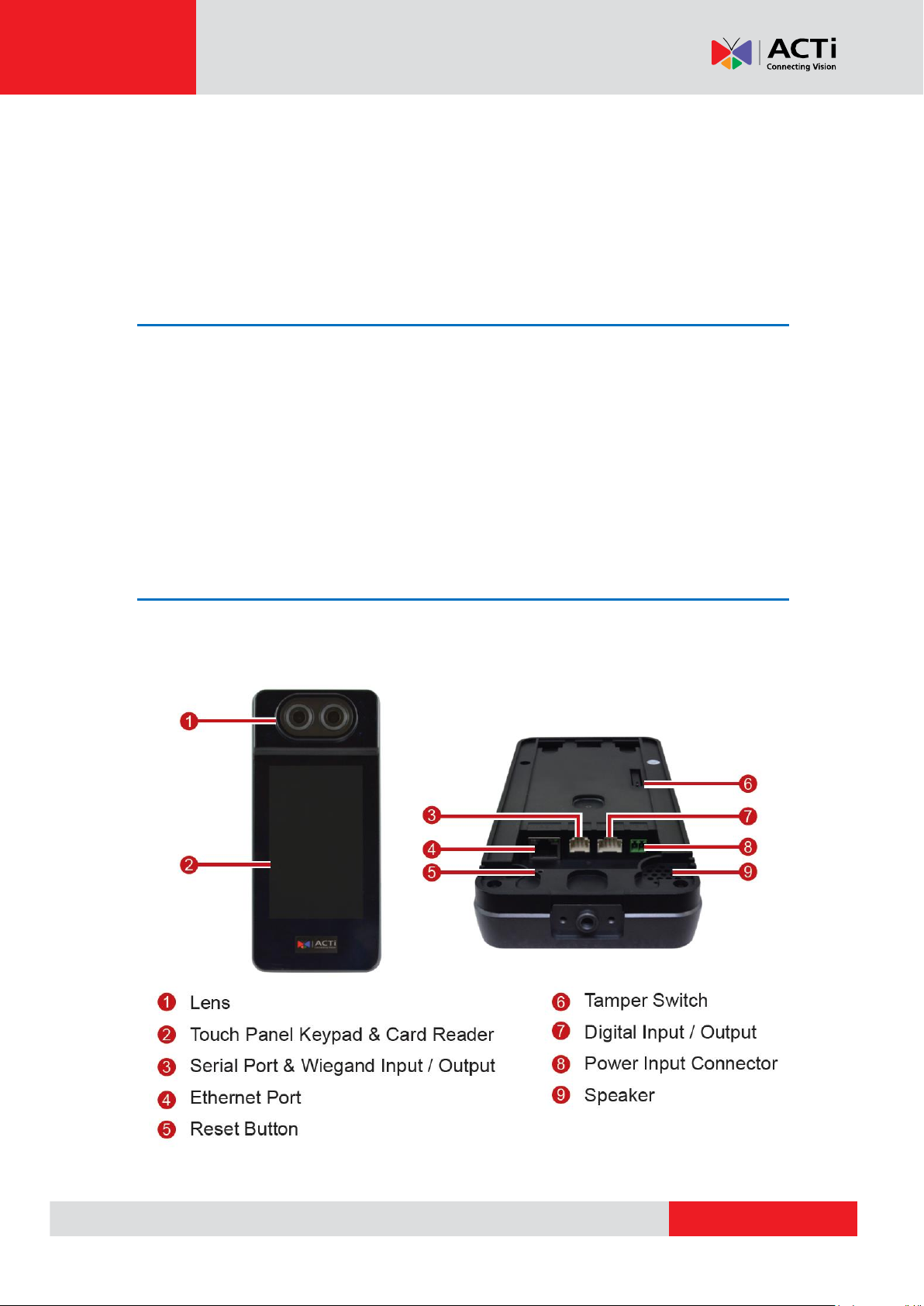
Step 2: Know the Device
The Device
2
Page 3
www.acti.com
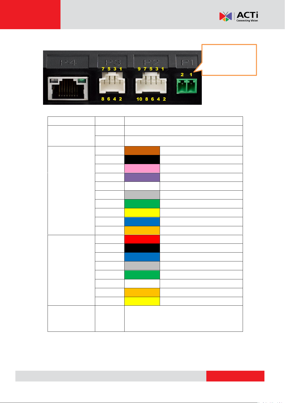
Port Pins
Port
Pin#
Definition & Color
P1
(Power)
1
12V POWER SUPPLY
2
12V POWER GND
P2
(Digital I/O)
1
Brown
12V DC OUT
2
Black
12V DC OUT
3
Pink
DOOR SENSOR INPUT
4
Purple
EXIT SWITCH INPUT
5
White
RELAY 1 COM
6
Gray
RELAY 2 COM
7
Green
RELAY 1 NC
8
Yellow
RELAY 2 NC
9
Blue
RELAY 1 NO
10
Orange
RELAY 2 NO
P3 (Communication)
1
Red
12V Power OUT
2
Black
12V Power OUT GND
3
Blue
Wiegand IN Data 0
4
Gray
Wiegand IN Data 1
5
Green
Wiegand OUT Data 0
6
White
Wiegand OUT Data 1
7
Orange
RS232 Tx
8
Yellow
RS232 Rx
P4
(Network)
Standard Gigabit Ethernet
DC 12V Power, 2Amp
Right: 12V DC
Left: Ground
Installation Guide
3
Page 4
www.acti.com
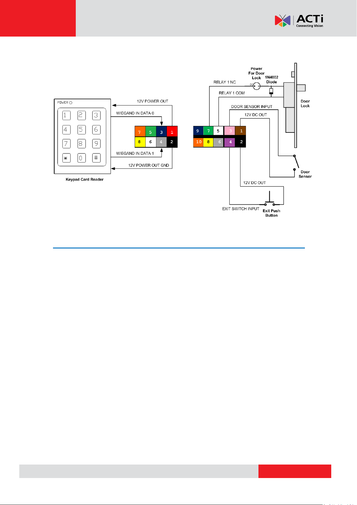
Typical Wiring Scheme
Installation Guide
Step 3: Connect Other Devices
1. Route the cables through the hole on the wall.
2. Connect the devices, such as the power adapter, to the cables with terminal block (refer
to the earlier sections to check the proper wiring connections).
4
Page 5
www.acti.com
Installation Guide
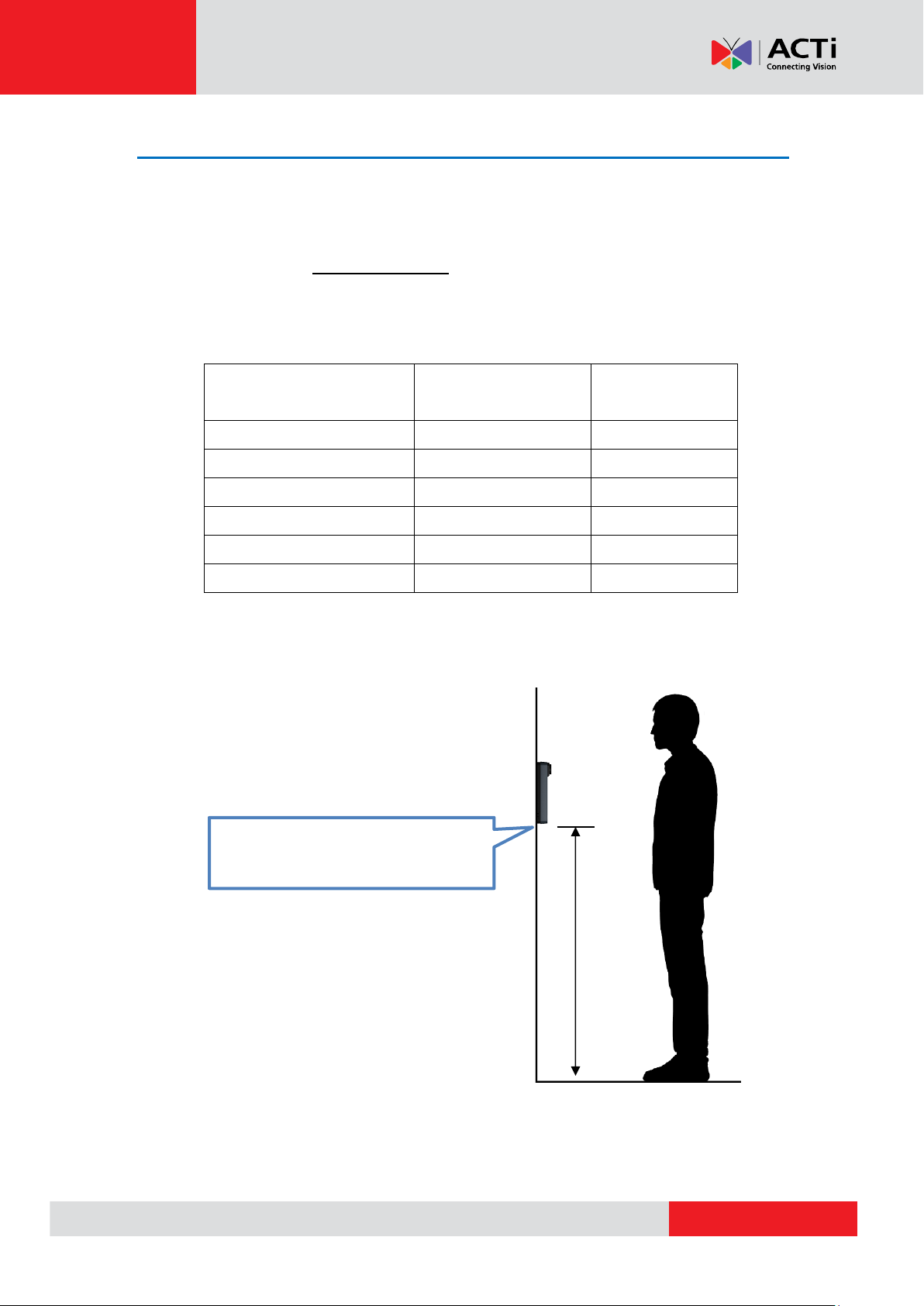
Installation
Height of Device (H)
Minimum
User Height
Maximum
User Height
1.05 m
1.30 m
1.70 m
1.10 m
1.35 m
1.75 m
1.15 m
1.40 m
1.80 m
1.20 m
1.45 m
1.85 m
1.25 m
1.50 m
1.90 m
1.30 m
1.55 m
1.95 m
Installation height (H) measured from
the bottom of the device to ground
Step 4: Install the Device
Installation Height Consideration
For installation with multiple devices, all units (including unit used for user enrollment)
must be installed at the same height
Installation height depends on the end user’s minimum and average height
See below table to find the appropriate installation height
5
Page 6
www.acti.com
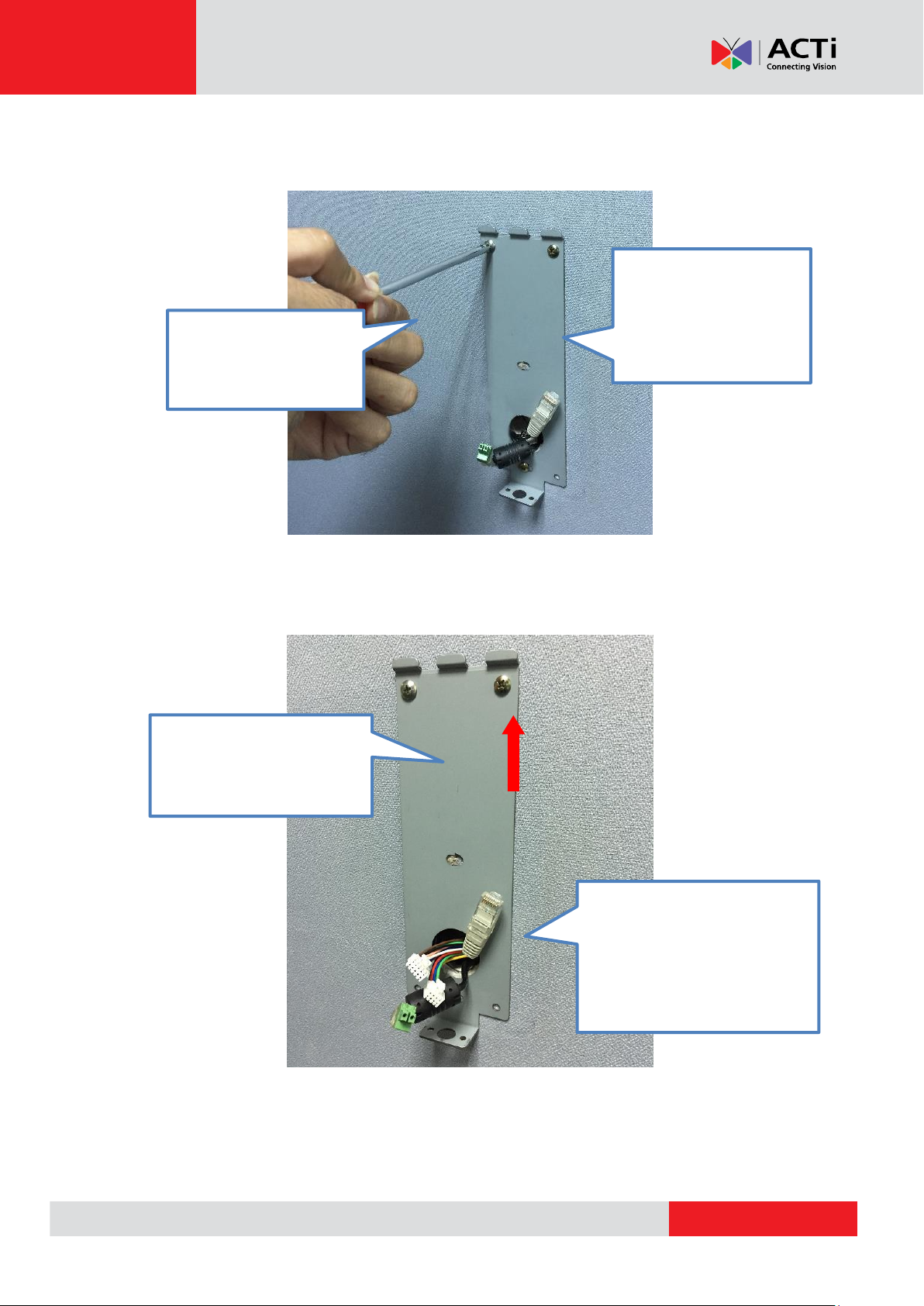
Installation Procedures
Decide the appropriate
height to mount the
device (refer to the table
above).
Ensure power, network,
communication, and I/O cables
are available from the opening
of the mounting bracket.
Ensure the device is
vertically installed and
parallel to a vertical wall.
Apply screws to tighten
the mounting bracket on
the wall.
Installation Guide
6
Page 7
www.acti.com
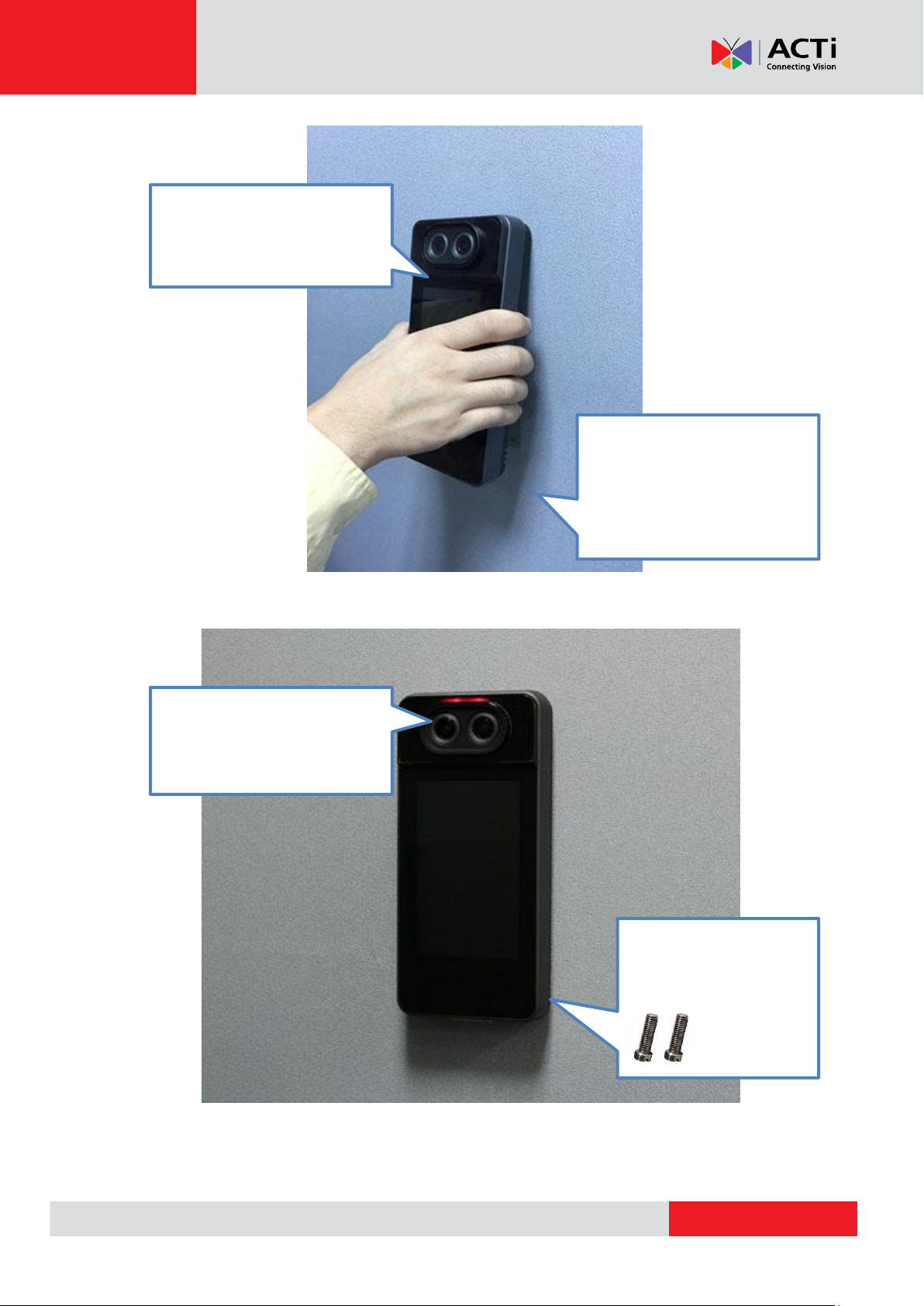
Installation Guide
Finally, mount the two (2)
bundled screws at the
bottom of the device.
Power up the device to test if all
the cables are connected
correctly
Connect all the cables to the
ports, and mount the device
gently.
Hook the top of the bracket and
press it down. Slide the unit
down to reach the bottom of the
bracket.
7
Page 8

Copyright © 2018, ACTi Corporation All Rights Reserved
7F, No. 1, Alley 20, Lane 407, Sec. 2, Ti-Ding Blvd., Neihu District, Taipei, Taiwan 114, R.O.C.
TEL : +886-2-2656-2588 FAX : +886-2-2656-2599
Email: sales@acti.com
 Loading...