

Page 1

USB and eSATA to SATA II
RAID Subsystem
User Manual
Revision 1.3
Page 2

USB and eSATA to SATA II RAID Subsystem
Table of Contents
Preface ............................................................................................................ 5
Before You Begin .......................................................................................... 6
Safety Guidelines................................................................................................................................................................... 6
Controller Configuration .................................................................................................................................................... 6
Packaging, Shipment and Delivery ................................................................................................................................ 6
Unpacking the Subsystem................................................................................................................................................. 7
Chapter 1 Introduction ............................................................................. 8
1.1 Key Features ................................................................................................................................................................. 9
1.2 Identifying Parts of the RAID Subsystem .......................................................................................................10
1.2.1 Front View ..........................................................................................................................................................10
1.2.1.1 Disk Trays ...................................................................................................................................................11
1.2.1.2 LCD Front Panel ......................................................................................................................................12
1.2.2 Rear View ............................................................................................................................................................13
1.3 Technical Specifications .........................................................................................................................................15
1.4 RAID Concepts ..........................................................................................................................................................16
1.5 Array Definition .........................................................................................................................................................21
1.5.1 Raid Set ...............................................................................................................................................................21
1.5.2 Volume Set ........................................................................................................................................................21
1.5.3 Easy to Use Features .....................................................................................................................................22
1.5.3.1 Instant Availability/Background Initialization ..............................................................................22
1.5.3.2 Array Roaming .........................................................................................................................................22
1.5.3.3 Online Capacity Expansion .................................................................................................................22
1.3.3.4 Online RAID Level and Stripe Size Migration .............................................................................23
1.5.4 High Availability .............................................................................................................................................24
1.5.4.1 Creating Hot Spares...............................................................................................................................24
1.5.4.2 Hot-Swap Disk Drive Support ...........................................................................................................24
1.3.4.3 Hot-Swap Disk Rebuild .........................................................................................................................24
Chapter 2 Getting Started ...................................................................... 25
2.1 Preparing the Subsystem and Powering On ................................................................................................25
2.2 Installing Hard Drives .............................................................................................................................................25
Chapter 3 RAID Configuration .............................................................. 27
3.1 Configuring Through a Terminal ........................................................................................................................27
2
User Manual
Page 3

USB and eSATA to SATA II RAID Subsystem
3.3 Menu Diagram ..........................................................................................................................................................33
3.4 Web browser-based Remote RAID management via R-Link Port .......................................................39
3.5 Quick Create ..............................................................................................................................................................41
3.6 Raid Set Functions ...................................................................................................................................................42
3.6.1 Create Raid Set .................................................................................................................................................42
3.6.2 Delete Raid Set .................................................................................................................................................43
3.6.3 Expand Raid Set ...............................................................................................................................................44
3.6.4 Offline Raid Set ................................................................................................................................................46
3.6.5 Activate Incomplete Raid Set .....................................................................................................................47
3.6.6 Create Hot Spare .............................................................................................................................................49
3.6.7 Delete Hot Spare .............................................................................................................................................49
3.6.8 Rescue Raid Set ................................................................................................................................................50
3.7 Volume Set Function .............................................................................................................................................51
3.7.1 Create Volume Set ..........................................................................................................................................51
3.7.2 Delete Volume Set ..........................................................................................................................................54
3.7.3 Modify Volume Set .........................................................................................................................................55
3.7.3.1 Volume Expansion ..................................................................................................................................56
3.7.4 Volume Set Migration ...................................................................................................................................56
3.7.5 Check Volume Set ............................................................................................................................................57
3.7.6 Stop Volume Set Check ................................................................................................................................58
3.8 Physical Drive ...........................................................................................................................................................59
3.8.1 Create Pass-Through Disk ............................................................................................................................59
3.8.2 Modify Pass-Through Disk ...........................................................................................................................60
3.8.3 Delete Pass-Through Disk ............................................................................................................................61
3.8.4 Identify Selected Drive ..................................................................................................................................61
3.9 System Controls ......................................................................................................................................................62
3.9.1 System Configuration .....................................................................................................................................62
3.9.2 iSCSI Configuration .........................................................................................................................................65
3.9.3 EtherNet Config................................................................................................................................................66
3.9.4 Alert By Mail Config .......................................................................................................................................68
3.9.5 SNMP Configuration ......................................................................................................................................69
3.9.6 NTP Configuration ...........................................................................................................................................70
3.9.7 View Events/Mute Beeper ............................................................................................................................71
3.9.8 Generate Test Event ........................................................................................................................................72
3.9.9 Clear Event Buffer ............................................................................................................................................73
3.9.10 Modify Password ...........................................................................................................................................74
3.9.11 Upgrade Firmware .........................................................................................................................................74
3.9.12 Shutdown Controller ...................................................................................................................................75
3.9.13 Restart Controller ..........................................................................................................................................75
3.10 Information Menu ................................................................................................................................................76
User Manual
3
Page 4

USB and eSATA to SATA II RAID Subsystem
3.10.1 RaidSet Hierarchy ...........................................................................................................................................76
3.10.2 System Information .......................................................................................................................................78
3.10.3 Hardware Monitor .........................................................................................................................................79
3.11 Creating New Raid Set or Reconfiguring an Existing Raid Set ..........................................................80
3.12 Upgrading the Firmware ......................................................................................................................................81
4
User Manual
Page 5
USB and eSATA to SATA II RAID Subsystem
Preface
About this manual
This manual provides information regarding the quick installation and hardware
features of the RAID subsystem. This document also describes how to use the
storage management software. Information contained in the manual has been
reviewed for accuracy, but not for product warranty because of the various
environment/OS/settings. Information and specifications will be changed without
further notice.
This manual uses section numbering for every topics being discussed for easy and
convenient way of finding information in accordance with the user’s needs. The
following icons are being used for some details and information to be considered in
going through with this manual:
Copyright
No part of this publication may be reproduced, stored in a retrieval system, or
transmitted in any form or by any means, electronic, mechanical, photocopying,
recording or otherwise, without the prior written consent.
Trademarks
All products and trade names used in this document are trademarks or registered
trademarks of their respective holders.
Changes
The material in this document is for information only an d is subject to change without
notice.
NOTES:
These are notes that contain useful information and tips
that the user must give attention to in going through with
the subsystem operation.
IMPORTANT!
These are the important information that the user must
remember.
WARNING!
These are the warnings that the user must follow to avoid
unnecessary errors and bodily injury during hardware and
software operation of the subsystem.
CAUTION:
These are the cautions that user must be aware to prevent
damage to the equipment and its components.
User Manual
5
Page 6

USB and eSATA to SATA II RAID Subsystem
Before You Begin
Before going through with this manual, you should read and focus to the following
safety guidelines. Notes about the subsystem’s controller configuration and the
product packaging and delivery are also included.
Safety Guidelines
To provide reasonable protection against any harm on the part of the user and to
obtain maximum performance, user is advised to be aware of the following safety
guidelines particularly in handling hardware components:
Upon receiving of the product:
Place the product in its proper location.
To avoid unnecessary dropping out, make sure that somebody is around for
immediate assistance.
It should be handled with care to avoid dropping that may cause damage to the
product. Always use the correct lifting procedures.
Upon installing of the product:
Ambient temperature is very important for the installation site. It must not exceed
30˚C. Due to seasonal climate changes; regulate the installation site temperature
making it not to exceed the allowed ambient temperature.
Before plugging-in any power cords, cables and connectors, make sure that the
power switches are turned off. Disconnect first any power connection if the power
supply module is being removed from the enclosure.
Outlets must be accessible to the equipment.
All external connections should be made using shielded cables and as much as
possible should not be performed by bare hand. Using anti-static hand gloves is
recommended.
In installing each component, secure all the mountin g screws and locks. Make sure
that all screws are fully tightened. Follow correctly all th e listed procedures in this
manual for reliable performance.
Controller Configuration
This RAID subsystem supports single controller configuration.
Packaging, Shipment and Delivery
Before removing the subsystem from the shipping carton, you should visually
inspect the physical condition of the shipping carton.
Unpack and verify that the contents of the shipping carton are complete and in
good condition.
Exterior damage to the shipping carton may indicate that the contents of the
carton are damaged.
If any damage is found, do not remove the components; contact the dealer where you
purchased the subsystem for further instructions.
6
User Manual
Page 7
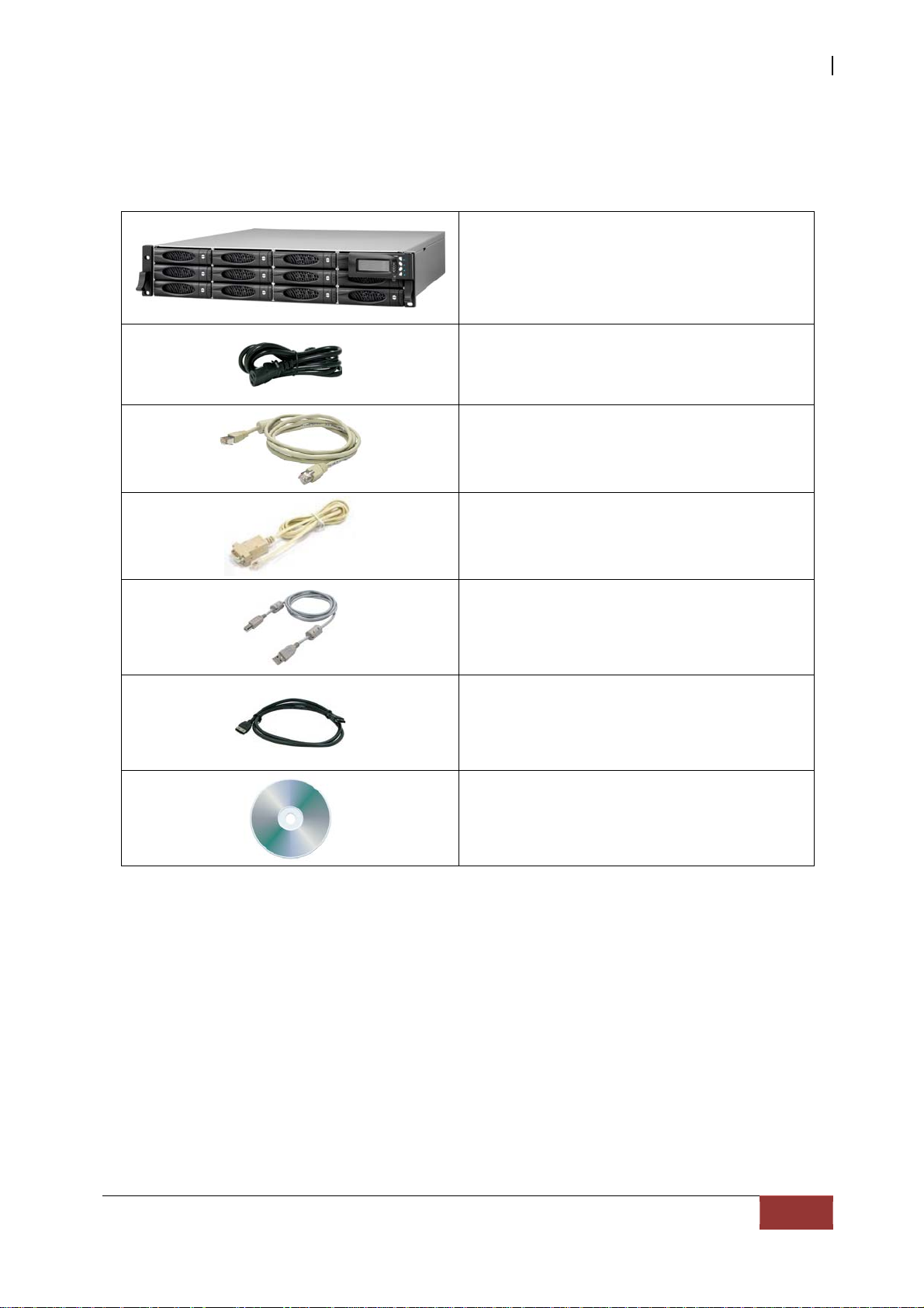
Unpacking the Subsystem
The package contains the following items:
RAID Subsystem Unit
USB and eSATA to SATA II RAID Subsystem
Two (2) power cords
One(1) RJ45 Ethernet cable
One(1) external serial cables RJ11-to-DB9
One(1) USB Cable
Two(2) external SATA cable
User Manual
NOTE: If any damage is found, contact the dealer or vendor for assistance.
User Manual
7
Page 8
USB and eSATA to SATA II RAID Subsystem
Chapter 1 Introduction
The RAID Subsystem
Unsurpassed Value
Most cost-effective SATA II RAID Subsystem
Application Flexibility
Multiple interface, extends useful life by adapting to future IT requirements
Easy Installation, upgrade & Maintenance
Provide a fast and easy way to install and upgrade the storage. Simplified
maintenance reduces ongoing IT labor costs.
Exceptional Manageability
Graphical User Interface (GUI) provides easy way for users to remotely manage
and configure the storage
Menu-driven interface make user a convenient way to maintain the storage by
locally LCD front console
Green Power Concept
Saves power by adopting the new technology “MAID” (Massive Arrays of Idle
Disks).
8
User Manual
Page 9

USB and eSATA to SATA II RAID Subsystem
1.1 Key Features
Subsystem Features:
USB 2.0 (480Mbps) / eSATA (3Gbps) / iSCSI (AoE)
Multiple Volumes for host access
Over 2TB support
Supports hot spare and automatic hot rebuild
Allows online capacity expansion within the enclosure
Local audible event notification alarm
Supports password protection
Ethernet Port interface for remote event notification
eSATA Support NCQ 32 Command, USB & iSCSI TCQ 256 Command
Transparent data protection for all popular operating systems
RAID Management:
Smart-function LCD panel
Environmental monitoring unit
Real time drive activity and status indicators
Web-based GUI management utility
User Manual
9
Page 10
USB and eSATA to SATA II RAID Subsystem
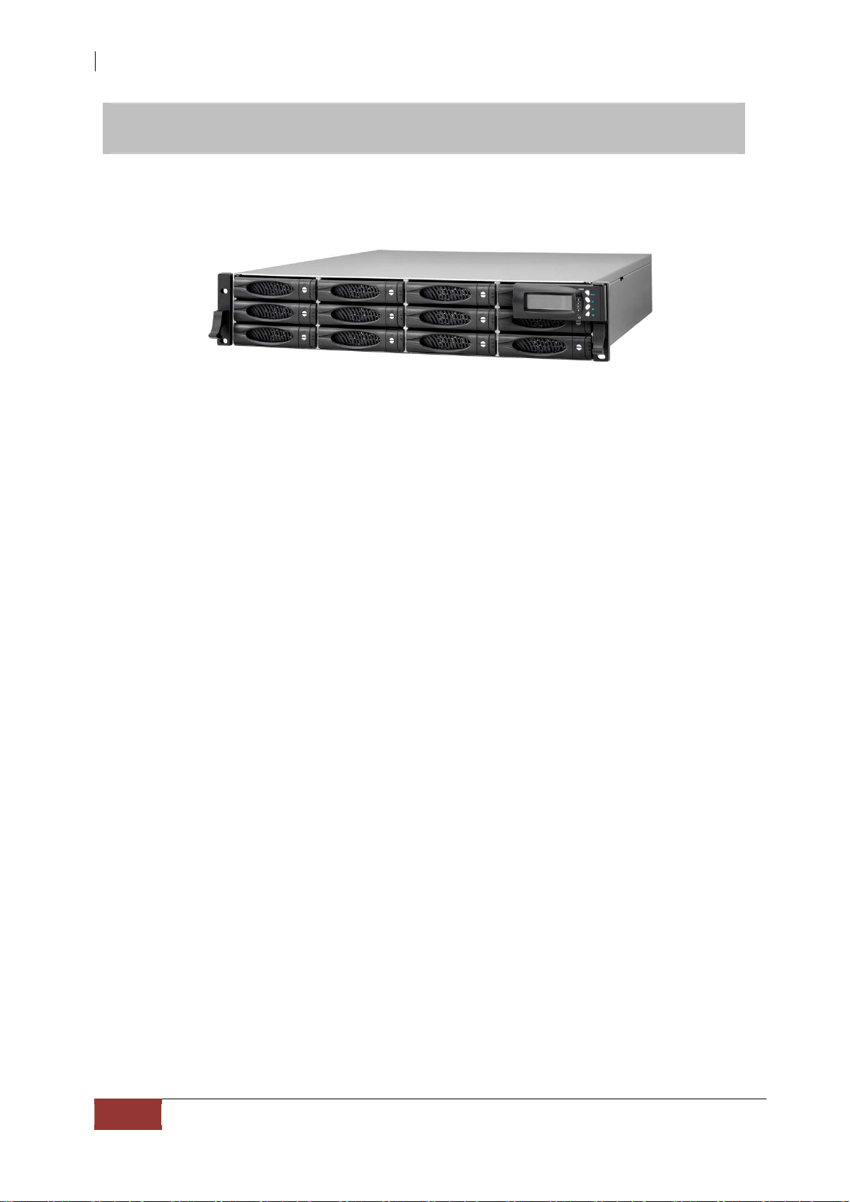
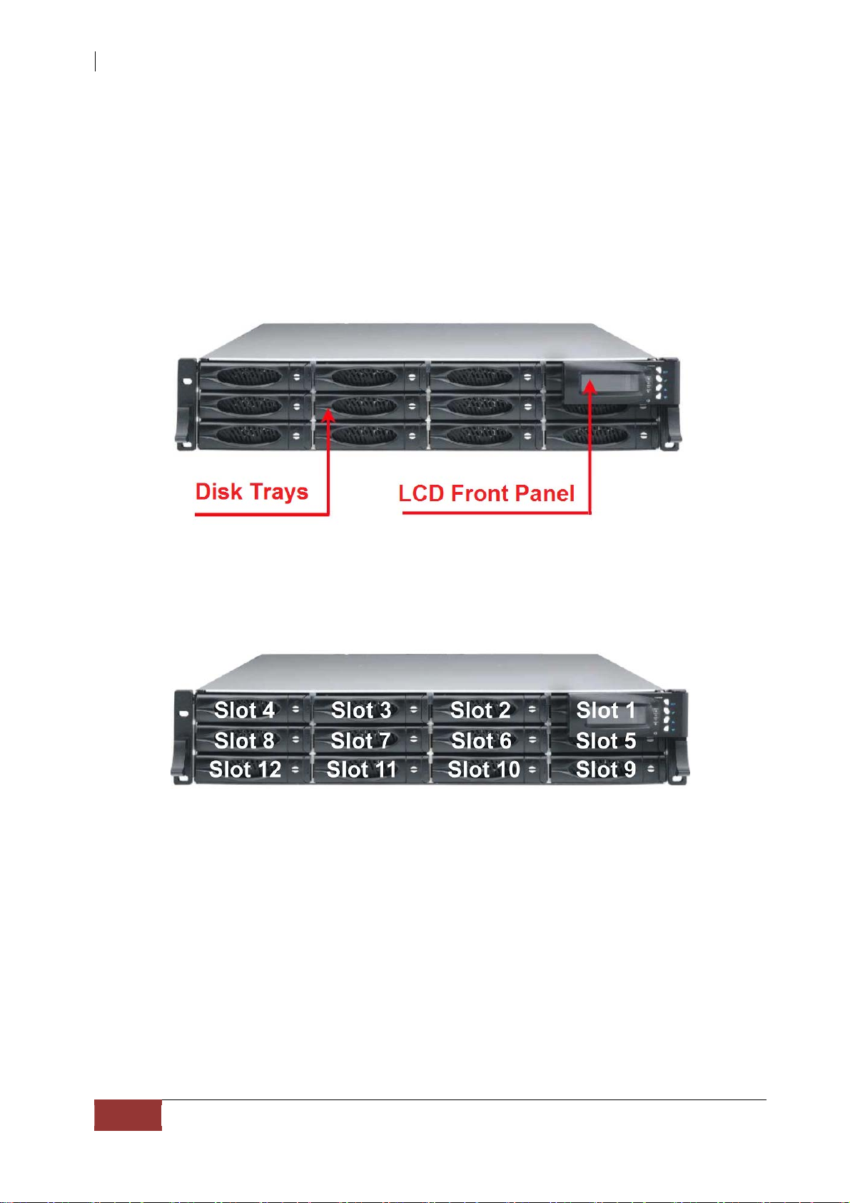
1.2 Identifying Parts of the RAID Subsystem
The illustrations below identify the various parts of the subsyst em.
1.2.1 Front View
10
User Manual
Page 11
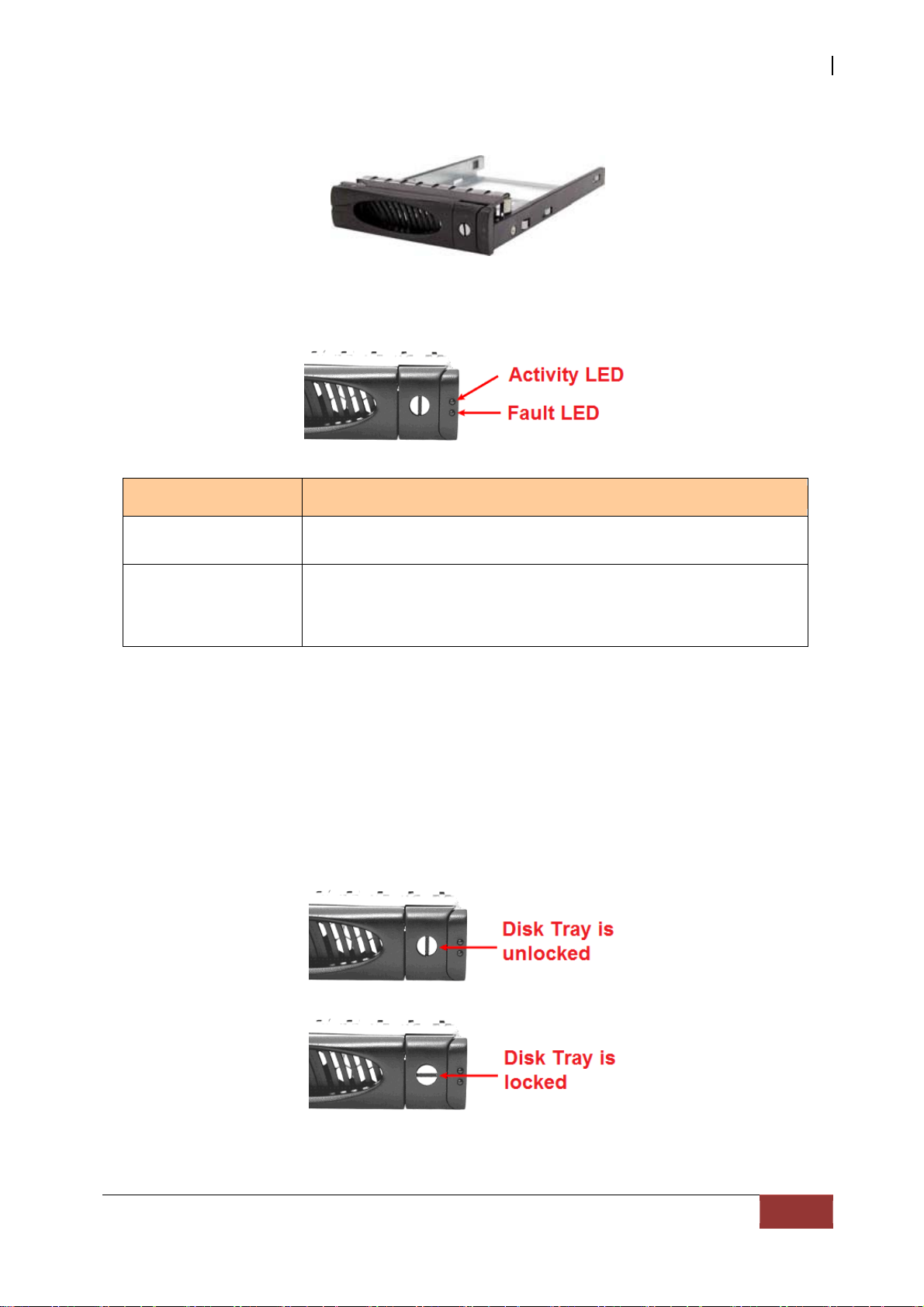
1.2.1.1 Disk Trays
HDD Status Indicator
USB and eSATA to SATA II RAID Subsystem
Part
HDD Activity LED
HDD Fault LED
Lock Indicator
Every Disk Tray is lockable and is fitted with a lock indicator to indicate
whether or not the tray is locked into the chassis or not. Each tray is also fitted with an
ergonomic handle for easy tray removal.
When the Lock Groove is horizontal, this indicates that the Disk Tray is locked. When
the Lock Groove is vertical, then the Disk Tray is unlocked.
This LED will blink blue when the hard drive is being accessed.
Green LED indicates power is on and hard drive status is good
for this slot. If hard drive is defective or failed, the LED is Red.
LED is off when there is no hard drive.
Function
User Manual
11
Page 12
USB and eSATA to SATA II RAID Subsystem
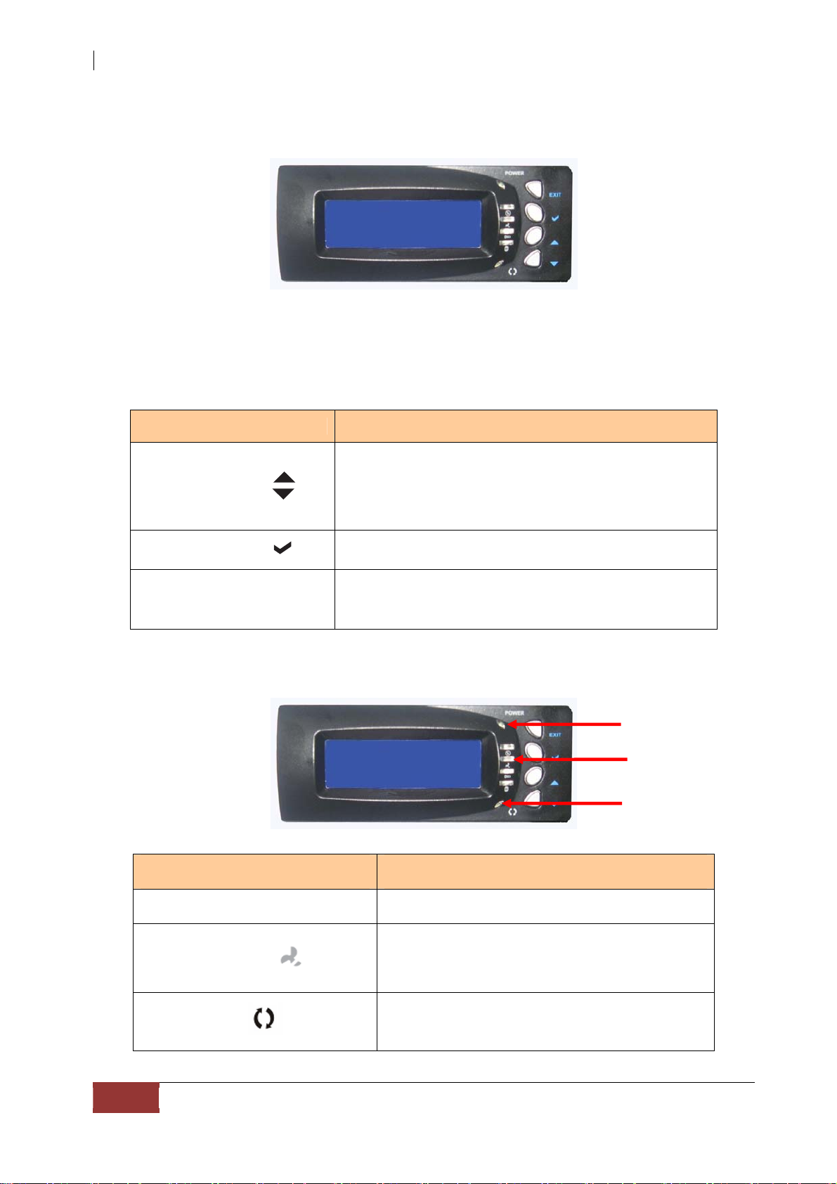
1.2.1.2 LCD Front Panel
Smart Function Front Panel
The sma rt LCD panel is a n o p t i on t o co nfigur e the RA ID subsyst em. If you are
configuring the subsystem using the LCD panel, press the Select button to login and
configure the RAID subsystem.
Parts Function
Use the Up or Down arrow keys to go through the
Up and Down
Arrow buttons
information on the LCD screen. This is also used to
move between each menu when you configure the
subsystem.
Select button This is used to enter the option you have selected.
Press this button to return to the previous menu.
Exit button EXIT
Environment Status LEDs
Parts Function
Power LED Green LED indicates power is ON.
Global fault LED
NOTE: This button can also be used to reset the
alarm beeper and turn off the Global fault LED.
Red LED indicates a problem within the
internal subsystem, such as fan fail/power
supply fail/disk fault.
Power LED
Global fault LED
Activity LED
This LED will blink blue when the Di s k Array
Activity LED
User Manual
12
is busy or active.
Page 13
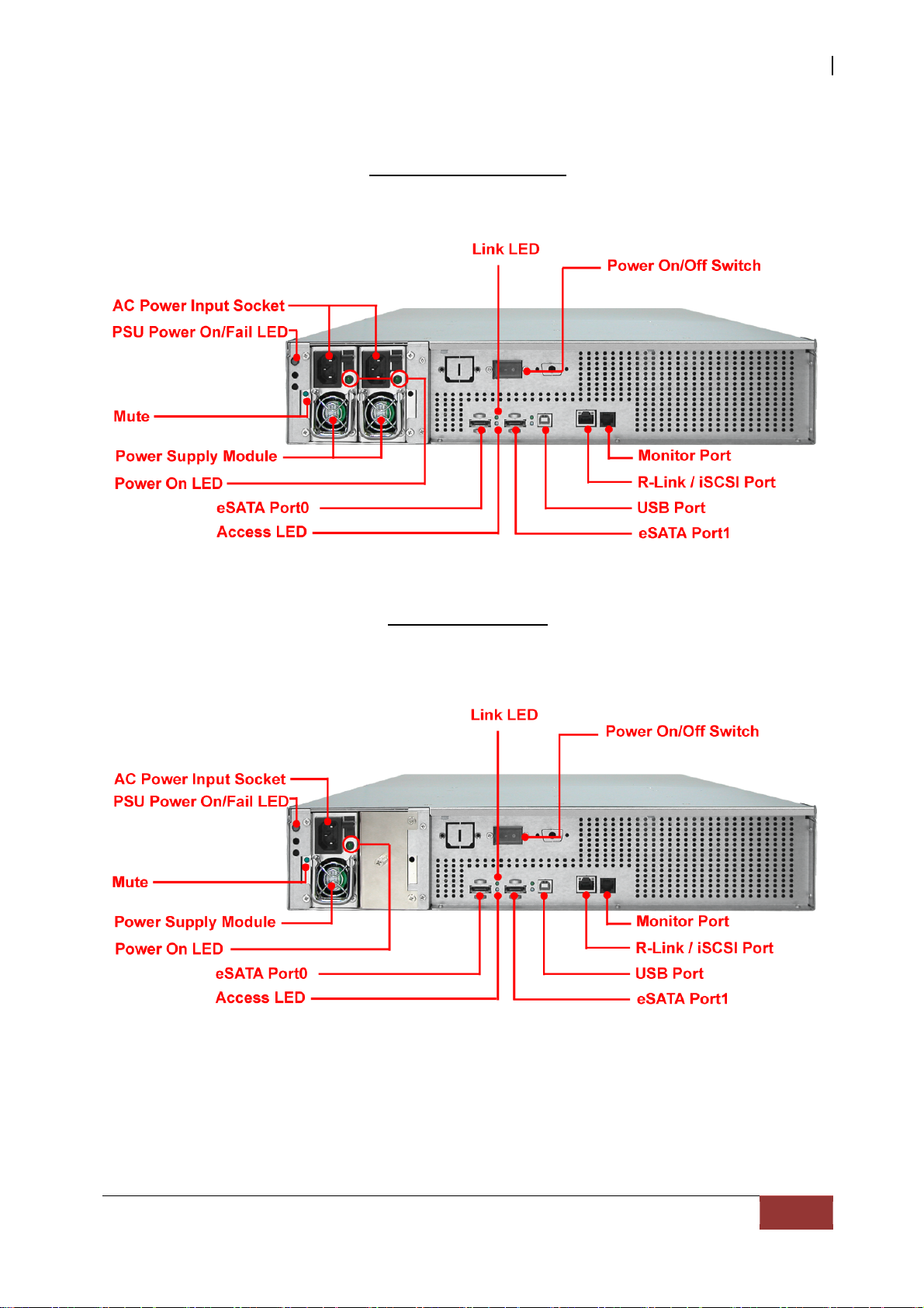
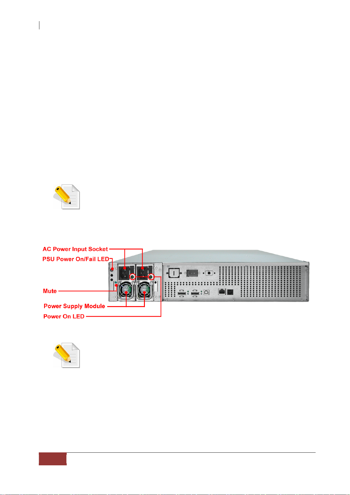
1.2.2 Rear View
Redundant Power Supply
USB and eSATA to SATA II RAID Subsystem
Single Power Supply
User Manual
13
Page 14
USB and eSATA to SATA II RAID Subsystem
1. eSATA Port - The subsystem has two external SATA II port for connecting to the host s ystem or
server.
Link LED: Green LED indicates eSATA is linking.
Access LED: The LED will blink blue when the eSATA is being accessed.
2. USB Port - The subsystem has one USB 2.0 port for connecting to the host system or server.
3. R-Link / iSCSI Port: Remote Link through RJ-45 Ethernet for remote management -
The subsystem is equipped with one 10/100/1000 Ethernet RJ45 LAN port. You use a w eb br ow se r
to manage the RAID subsystem through Ethernet for remote configuration and monitoring.
The R-Link Port is also used for accessing LUN via iSCSI (AoE) protocol.
4. Monitor Port - The subsystem is equipped with a serial moni tor port allowing you to connect a
PC or terminal.
5. Power Supply Unit - The subsystem has dual or single power supply unit.
NOTE: In order to maintain the system I/O performance, it is not
recommended to access the storage from the different host
interfaces at the same time.
NOTE: After power on, the Power On LED is green, the PSU Power
On/Fail LED is also green. When one Power Supply Module fails, the
Power On/Fail LED is orange.
14
User Manual
Page 15
USB and eSATA to SATA II RAID Subsystem
1.3 Technical Specifications
Form-factor 2U 19-inch rackmount chassis
RAID processor 400MHz storage I/O processor
RAID level 0, 1, 10, 3, 5, 6 and JBOD
Cache memory 256MB
No. of Channels (Host and
Drive)
Host bus interface USB 2.0 / eSATA x 2 / R-Link (iSCSI)
Drive bus interface SATA II (Up to 3.0Gbps)
Data transfer rate
Hot-swap drive tray Twelve (12) 1-inch trays
Power supplies
Cooling fan 2
4 +12
Support up to 480Mbps (USB 2.0)
Support up to 3.0Gbps (SATA II)
Support 10 / 100 / 1000 Mbps Ethernet
400W x1(upgradeable) or 400W x2
Redundant power supplies w/PFC
Password protection Yes
Audible alarm Yes
Failed drive indicators Yes
Failed drive auto rebuild Yes
Online consistency check Yes
Online expansion Yes
Array Roaming Yes
Online RAID level/ stripe size
migration
Instant availability and
background initialization
Environment monitor Yes
Auto spare support Yes
Bad block auto-remapping Yes
Remote management Yes
MAID support Yes
Over 2TB support
Power requirements
Relative Humidity: 10% ~ 85% Non-condensing
Yes
Yes
Windows OS which supports GPT
(Windows XP/x64, 2003/SP1 or 64-bit,
Vista,2008)
Mac OS 10 or later, Linux Kernel 2.6 or later
AC 100V ~ 240V full range
8A ~ 4A, 47Hz ~ 63Hz
Operating Temp: 10oC ~ 40oC (50oF ~ 104oF)
Physical Dimensions: 88(H) x 482(W) x 500(D)mm
Note: Specifications are subject to change without notice. All company and
product names are trademarks of their respective owners.
User Manual
15
Page 16
USB and eSATA to SATA II RAID Subsystem
1.4 RAID Concepts
RAID Fundamentals
The basic idea of RAID (Redundant Array of Independent Disks) is to combine multiple
inexpensive disk drives into an array of disk drives to obtain performance, capacity and
reliability that exceeds that of a single large drive. The array of drives appears to the host
computer as a single logical drive.
Five types of array architectures, RAID 1 through RAID 5, were originally defined; each
provides disk fault-tolerance with different compromises in features and performance. In
addition to these five redundant array architectures, it has become popular to refer to a
non-redundant array of disk drives as a RAID 0 arrays.
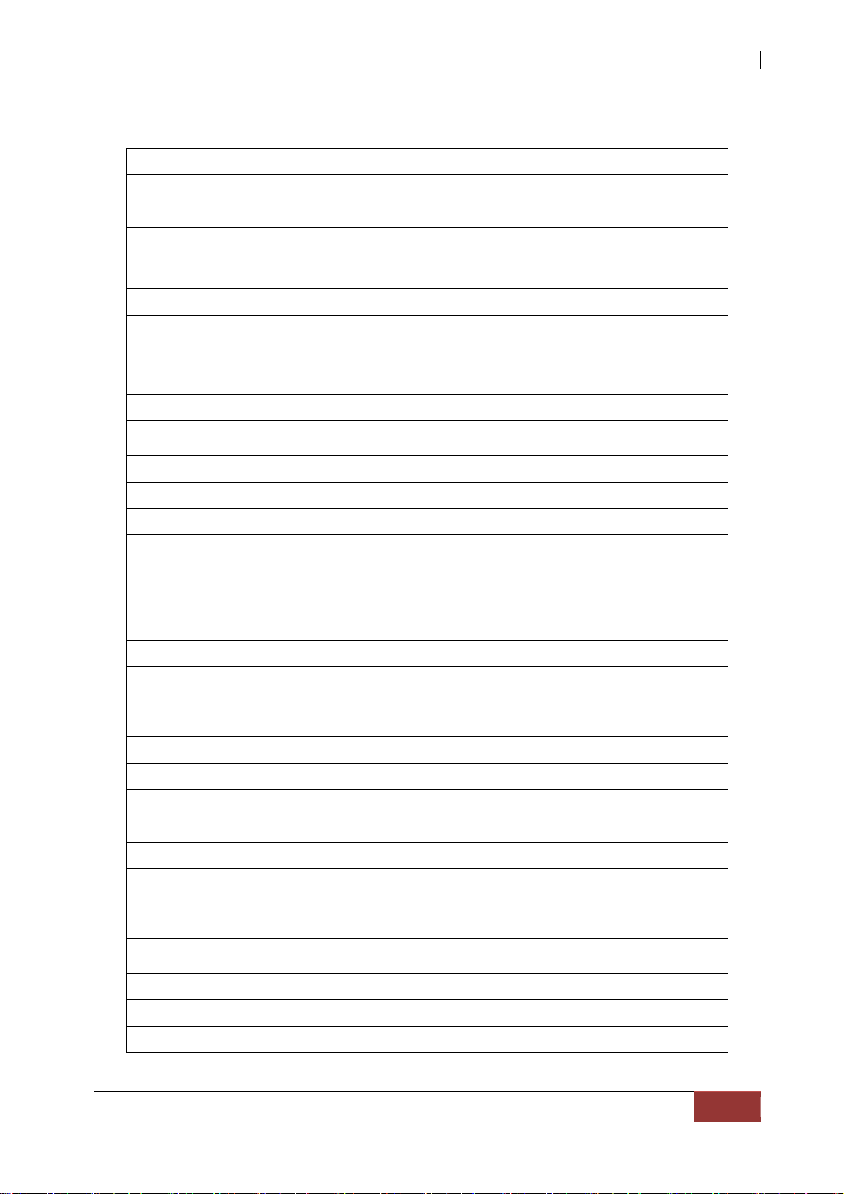
Disk Striping
Fundamental to RAID technology is striping. This is a method of combining multiple drives
into one logical storage unit. Striping partitions the storage space of each drive into
stripes, which can be as small as one sector (512 bytes) or as large as several megabytes.
These stripes are then interleaved in a rotating sequence, so that the combined space is
composed alternately of stripes from each drive. The specific type of operating
environment determines whether large or small stripes should be used.
Most operating systems today support concurrent disk I/O operations across multiple
drives. However, in order to maximize throughput for the disk subsystem, the I/O load
must be balanced across all the drives so that each drive can be kept busy as much as
possible. In a multiple drive system without striping, the disk I/O load is never perfectly
balanced. Some drives will contain data files that are frequently accessed and some drives
will rarely be accessed.
By striping the drives in the array with stripes large enough so that each record falls
entirely within one stripe, most records can be evenly distributed across all drives. This
keeps all drives in the array busy during heavy load situations. This situation allows all
drives to work concurrently on different I/O operations, and thus maximize the number of
simultaneous I/O operations that can be performed by the array.
16
User Manual
Page 17
USB and eSATA to SATA II RAID Subsystem
Definition of RAID Levels
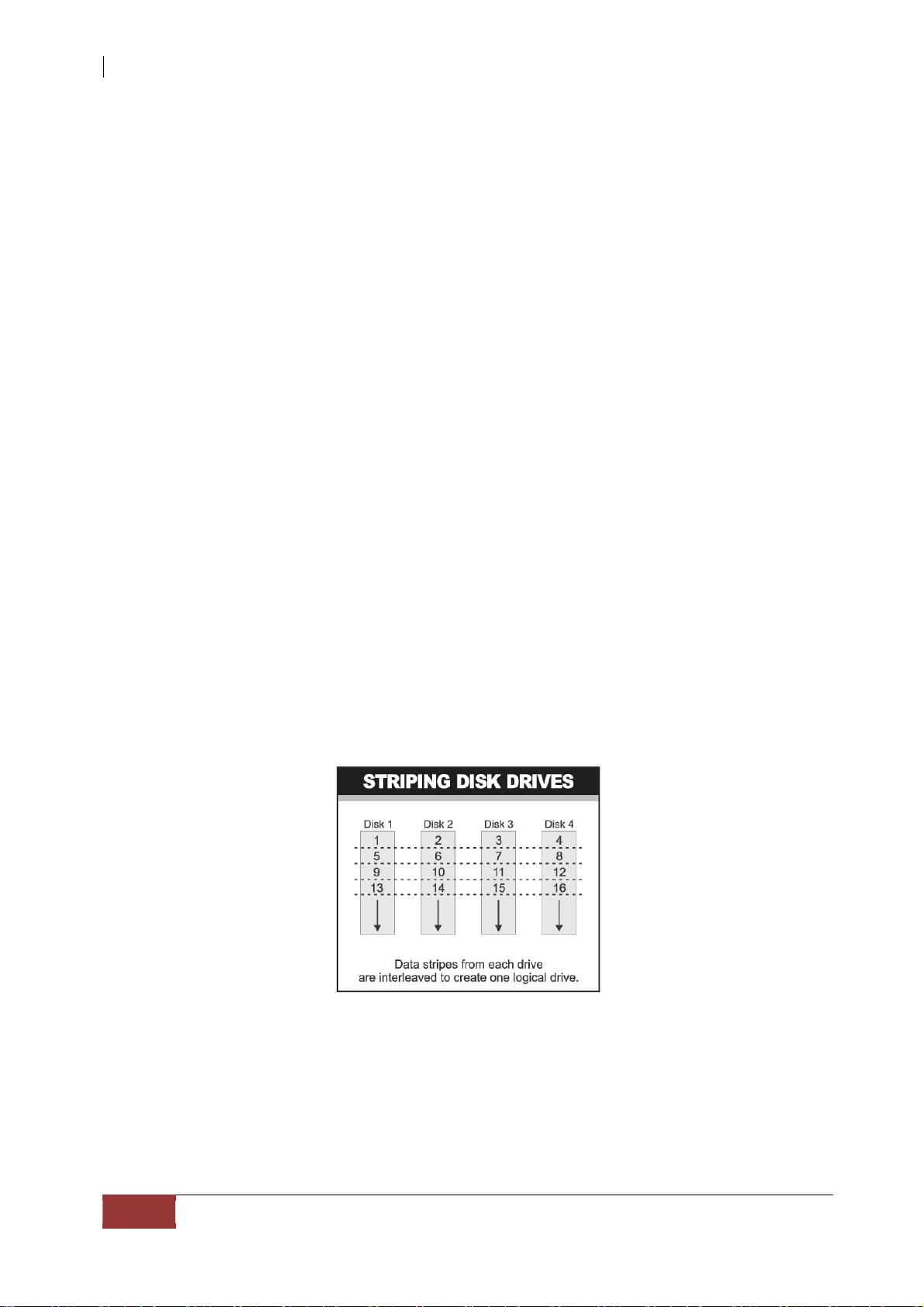
RAID 0 is typically defined as a group of striped disk drives without parity or data
redundancy. RAID 0 arrays can be configured with large stripes for multi-user
environments or small stripes for single-user systems that access long sequential records.
RAID 0 arrays deliver the best data storage efficiency and performance of any array type.
The disadvantage is that if one drive in a RAID 0 array fails, the entire array fails.
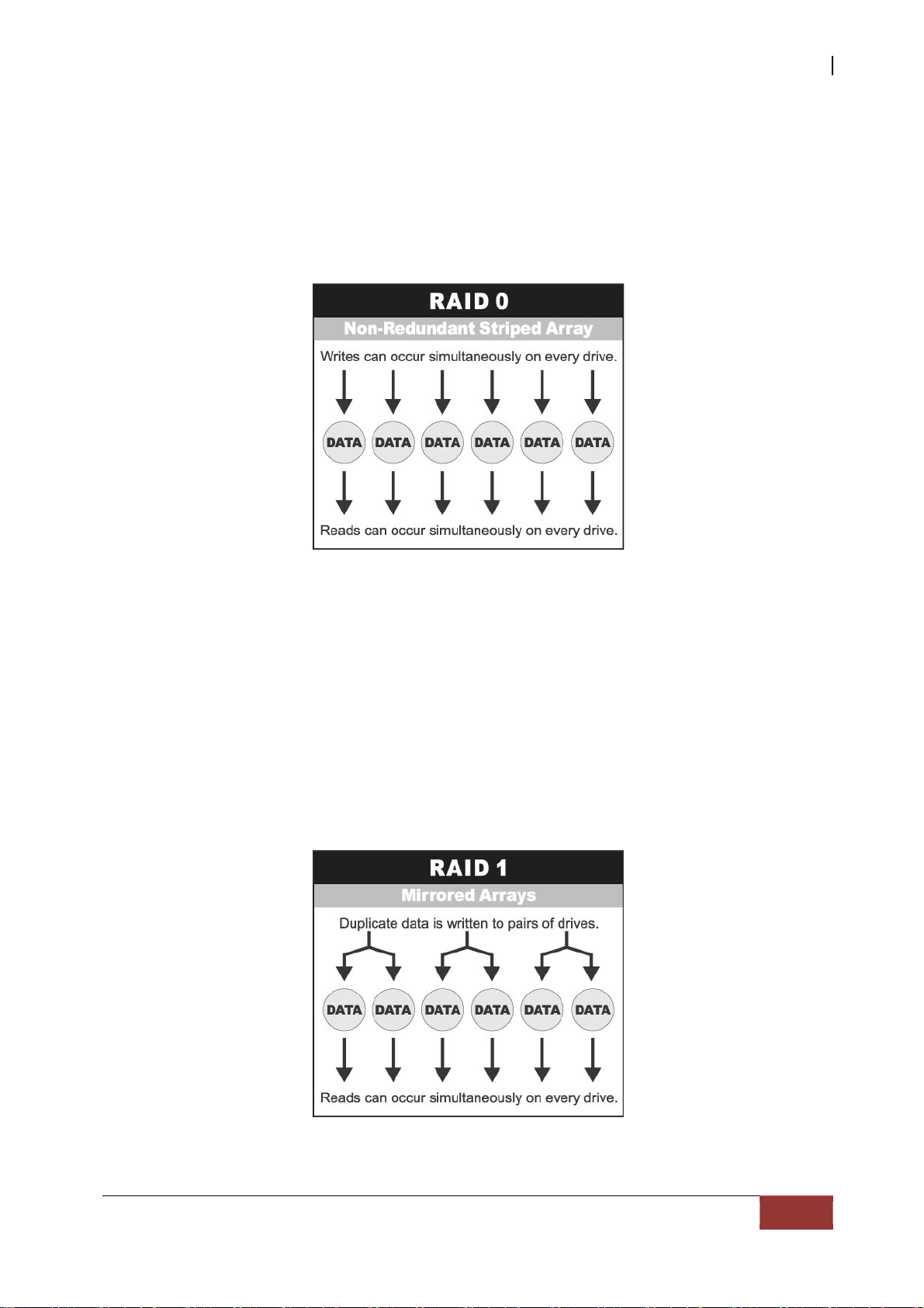
RAID 1, also known as disk mirroring, is simply a pair of disk drives that store duplicate
data but appear to the computer as a single drive. Although striping is not used within a
single mirrored drive pair, multiple RAID 1 arrays can be striped together to create a
single large array consisting of pairs of mirrored drives. All wr ites must go to both drives
of a mirrored pair so that the information on the drives is kept identical. However, each
individual drive can perform simultaneous, independent read operations. Mirroring thus
doubles the read performance of a single non-mirrored drive and while the write
performance is unchanged. RAID 1 delivers the best performance of any redundant array
type. In addition, there is less performance degradation during drive failure than in RAID 5
arrays.
User Manual
17
Page 18
USB and eSATA to SATA II RAID Subsystem
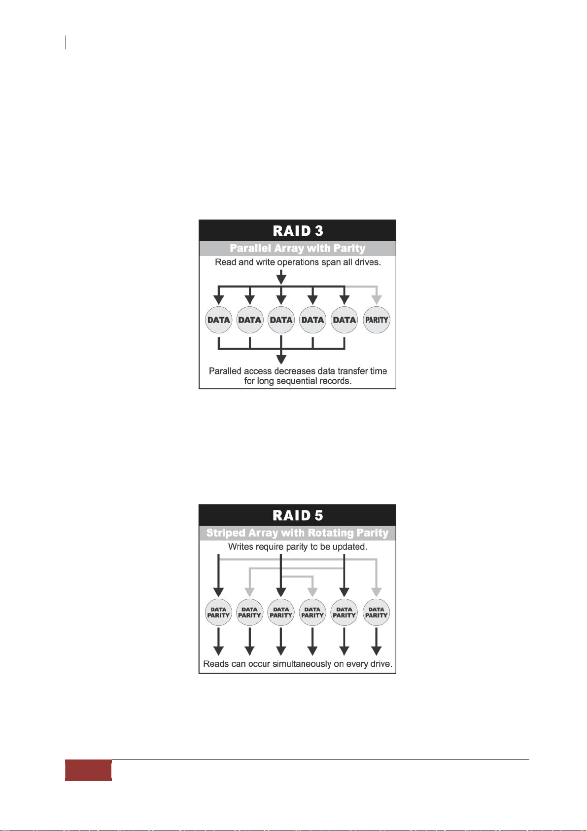
RAID 3 sector-stripes data across groups of drives, but one drive in the group is
dedicated to storing parity information. RAID 3 relies on the embedded ECC in each sector
for error detection. In the case of drive failure, data recovery is accomplished by
calculating the exclusive OR (XOR) of the information recorded on the remaining driv es.
Records typically span all drives, which optimizes the disk transfer rate. Because each I/O
request accesses every drive in the array, RAID 3 arrays can satisfy only one I/O request
at a time. RAID 3 delivers the best performance for single-user, single-tasking
environments with long records. Synchronized-spindle drives are required for RAID 3
arrays in order to avoid performance degradation with short records. RAID 5 arrays with
small stripes can yield similar performance to RAID 3 arrays.
Under RAID 5 parity information is distributed across all the drives. Since there is no
dedicated parity drive, all drives contain data and read operations can be overlapped on
every drive in the array. Write operations will typically access one data drive and one
parity drive. However, because different records store their parity on different drives,
write operations can usually be overlapped.
Dual-level RAID achieves a balance between the increased data availability inh erent in
RAID 1 and the increased read performance inherent in disk striping (RAID 0). These
arrays are sometimes referred to as RAID 10.
18
User Manual
Page 19
USB and eSATA to SATA II RAID Subsystem
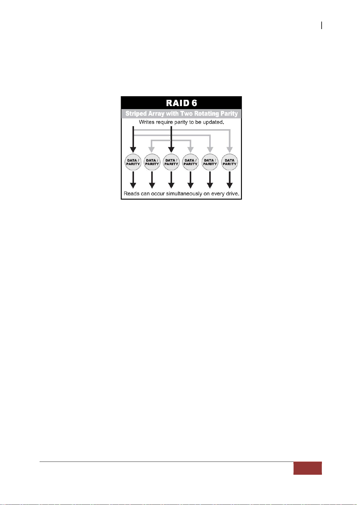
RAID 6 is similar to RAID 5 in that data protection is achieved by writing parity
information to the physical drives in the array. With RAID 6, however, two sets of parity
data are used. These two sets are different, and each set occupies a capacity equivalent to
that of one of the constituent drives. The main advantage of RAID 6 is High data
availability – any two drives can fail withou t loss of critical data.
In summary:
RAID 0 is the fastest and most efficient array type but offers no fault-tolerance. RAID
0 requires a minimum of one drive.
RAID 1 is the best choice for performance-critical, fault-tolerant environments. RAID 1
is the only choice for fault-tolerance if no more than two drives are used.
RAID 3 can be used to speed up data transfer and provide fault-tolerance in single-
user environments that access long sequential records. However, RAID 3 does not
allow overlapping of multiple I/O operations and requires synchronized-spindle drives
to avoid performance degradation with short records. RAID 5 with a small stripe size
offers similar performance.
RAID 5 combines efficient, fault-tolerant data storage with good performance
characteristics. However, write performance and performance during drive failure is
slower than with RAID 1. Rebuild operations also require more time than with RAID 1
because parity information is also reconstructed. At least three drives are required f or
RAID 5 arrays.
RAID 6 is essentially an extension of RAID level 5 which allows for additional fault
tolerance by using a second independent distributed parity scheme (two-dimensional
parity). Data is striped on a block level across a set of drives, just like in RAID 5, and a
second set of parity is calculated and written across all the drives; RAID 6 provides for
an extremely high data fault tolerance and can sustain multiple simultaneous drive
failures. It is a perfect solution for mission critical applications.
User Manual
19
Page 20
USB and eSATA to SATA II RAID Subsystem
RAID Management
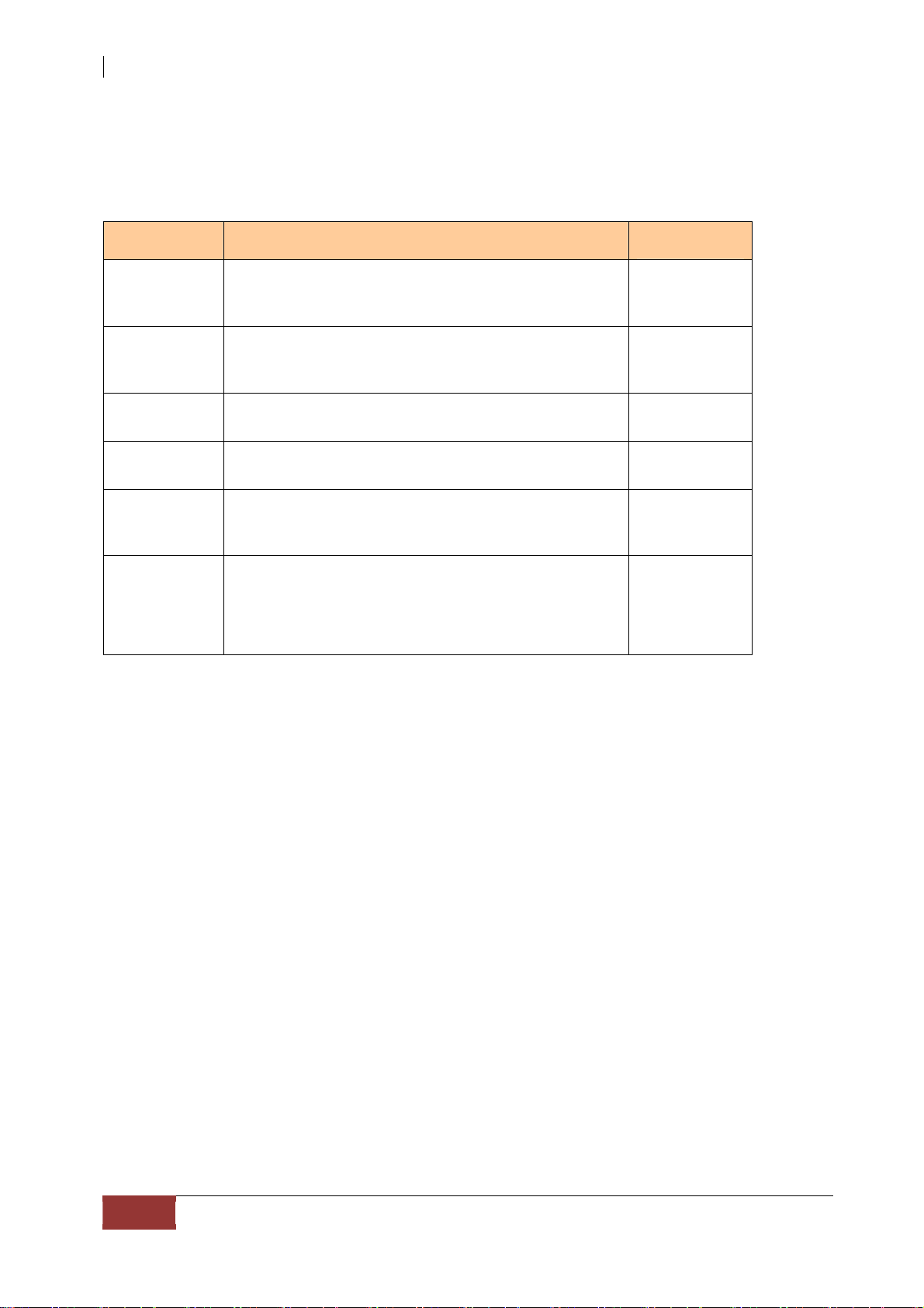
The subsystem can implement several different levels of RAID technology. RAID levels
supported by the subsystem are shown below.
RAID Level Description Min. Drives
Block striping is provide, which yields higher
0
1
performance than with individual drives. There
is no redundancy.
Drives are paired and mirrored. All data is 100%
duplicated on an equivalent drive. Fully
redundant.
1
2
3
5
10
6
Data is striped across several physical drives.
Parity protection is used for data redundancy.
Data is striped across several physical drives.
Parity protection is used for data redundancy.
Combination of RAID levels 1 and 0. This level
provides redundancy through mirroring and
striping.
Data is striped across several physical drives.
Parity protection is used for data redundancy.
Requires N+2 drives to implement because of
two-dimensional parity scheme
3
3
4
4
20
User Manual
Page 21
USB and eSATA to SATA II RAID Subsystem
1.5 Array Definition
1.5.1 Raid Set
A Raid Set is a group of disk drives containing one or more logical volumes called Volume
Sets. It is not possible to have multiple Raid Sets on the same disk drives.
A Volume Set must be created either on an existing Raid Set or on a group of available
individual disk drives (disk drives that are not yet a part of a Raid Set). If there are
existing Raid Sets with available raw capacity, new Volume Set can be created. New
Volume Set can also be created on an existing Raid Set without free raw capacity by
expanding the Raid Set using available disk drive(s) which is/are not yet Raid Set
member. If disk drives of different capacity are grouped together in a Raid Set, then the
capacity of the smallest disk will become the effective capacity of all the disks in the
Raid Set.
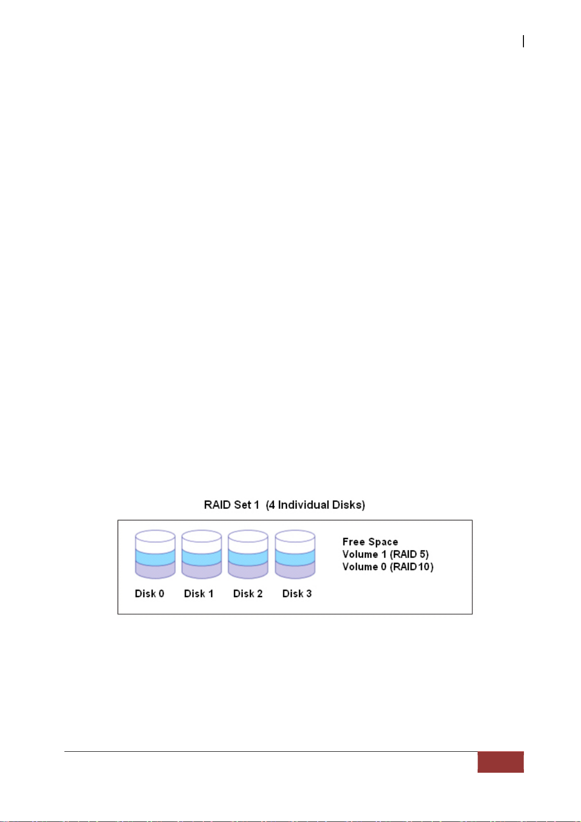
1.5.2 Volume Set
A Volu me Set is seen by the host system as a single logical device. It is organized in a
RAID level with one or more physical disks. RAID level refers to the level of data
performance and protection of a Volume Set. A Volume Set capacity can consume all
or a portion of the raw capacity available in a Raid Set. Multiple Volume Sets can
exist on a group of disks in a Raid Set. Additional Volume Sets created in a specified
Raid Set will reside on all the physical disks in the Raid Set. Thus each Volume Set on
the Raid Set will have its data spread evenly across all the disks in the Raid Set. Volume
Sets of different RAID levels may coexist on the same Raid Set.
In the illustration below, Volume 1 can be assigned a RAID 5 level while Volume 0 might
be assigned a RAID 10 level.
User Manual
21
Page 22
USB and eSATA to SATA II RAID Subsystem
1.5.3 Easy to Use Fe atures
1.5.3.1 Instant Availability/Background Initialization
RAID 0 and RAID 1 Volume Set can be used immediately after the creation. But the RAID
3, 5 and 6 Volume Sets must be initialized to generate the parity. In the Background Mode
initialization, the initializ ation proceeds as a background task, the Volume Set is fully
accessible for system reads and writes. The operating system can instantly access to the
newly created Volume Sets without waiting for the in itialization to be completed. One
disadvantage of this is that the initialization process takes lon g er time. In Foreground
Mode initialization, the initialization process is fast er but must be completed first before
the Volume Set is ready for system access.
1.5.3.2 Array Roaming
The RAID subsystem stores configuration information both in NVRAM and on the disk
drives. This protects the configuration settings in the case of a disk drive or controller
failure. Array roaming allows the administrator the ability to move a complete Raid Set to
another system without losing RAID configuration and data on that Raid Set. If a RAID
enclosure fails to work, the Raid Set disk drives can be moved to another enclosure and
inserted in any order.
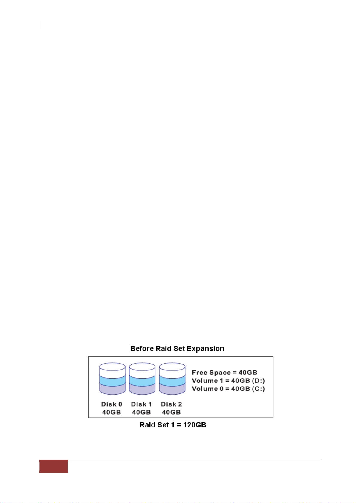
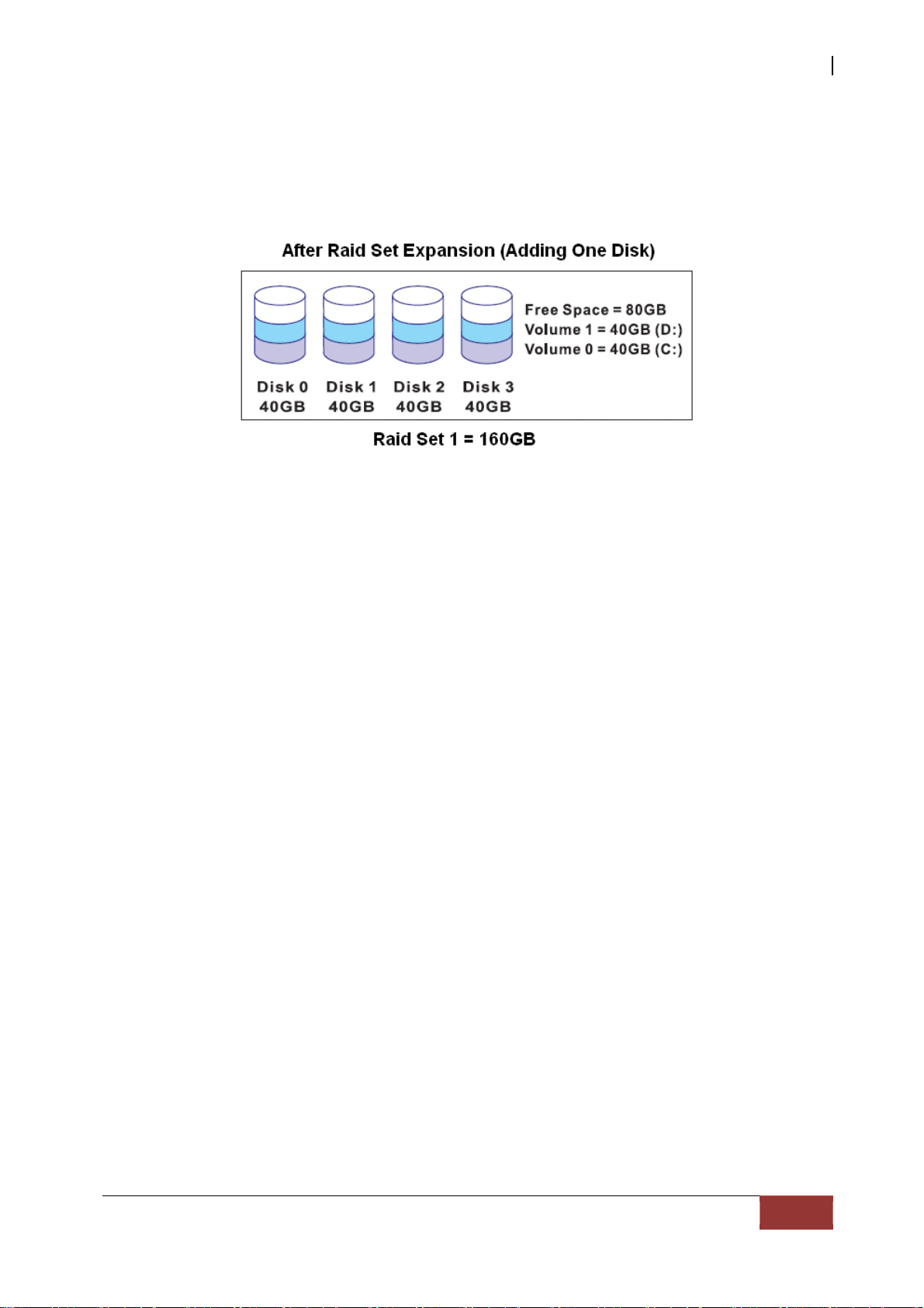
1.5.3.3 Online Capacity Expansion
Online Capacity Expansion makes it possible to add one or more physical drives to a Raid
Set, while the server is in operation, eliminating the need to back up and restore after
reconfiguring the Raid Set. When disks are added to a Raid Set, unused capacity is added
at the end of the Raid Set. Data on the existing Volume Sets residing on that Raid Set is
redistributed evenly across all the disks. A contiguous block of unused capacity is made
available on the Raid Set. The unused capacity can be used to create additional Volume
Set. The expansion process is illustrated as follows.
22
User Manual
Page 23
USB and eSATA to SATA II RAID Subsystem
The RAID subsystem controller redistributes the original Volume Set over the original and
newly added disks, using the same RAID level configuration. The unused capacity on the
expand Raid Set can then be used to create an additional Volume Sets, with a different
RAID level setting as needed by user.
1.3.3.4 Online RAID Level and Stri pe Size M igration
User can do migration on both the RAID level and Stripe Size of an existing Volume Set
while the server is online and the Volume Set is in use. Online RAID level/stripe size
migration can prove helpful during performance tuning activities as well as in the event
that additional physical disks are added to the RAID subsystem. For example, in a system
using two drives in RAID level 1, you could add capacity and retain fault tolerance by
adding one drive. With the addition of third disk, you have the option of adding this disk to
your existing RAID logical drive and migrating from RAID level 1 to 5. The result wou ld be
parity fault tolerance and double the available capacity without taking the system off.
User Manual
23
Page 24
USB and eSATA to SATA II RAID Subsystem
1.5.4 High Availability
1.5.4.1 Creating Hot Spares
A hot spare drive is an unused online available drive, which is ready to replace a failed
disk drive. In a RAID level 1, 10, 3, 5 or 6 Raid Set, any unused online av ailable drive
installed but not belonging to a Raid Set can be defined as a hot spare drive. Hot spares
permit you to replace failed drives without powering down the system. When the RAID
subsystem detects a drive failure, the system will do automatic and transparent rebuild
using the hot spare drives. The Raid Set will be reconfigured and rebuilt in the background
while the RAID subsystem continues to handle system request. During the automatic
rebuild process, system activity will continue as normal, however, the system performance
and fault tolerance will be affected.
IMPORTANT: The hot spare must have at least the same or more
capac it y a s t he drive it replaces.
1.5.4.2 Hot-Swap Disk Drive Support
The RAID subsystem has built-in protection circuit to support the replacement of SATA
II hard disk drives without having to shut down or reboot the system. The removable
hard drive tray can deliver “hot swappable” fault-tolerant RAID so lution a t a price mu ch
less than the cost of conventional SCSI hard disk RAID subsystems. This feature is
provided in the RAID subsystem for advance fault tolerant RAID protection and “online”
drive replacement.
1.3.4.3 Hot-Swap Disk Rebuild
The Hot-Swap feature can be used to rebuild Raid Sets with data redund ancy such as
RAID level 1, 10, 3, 5 and 6. If a hot spare is not available, the failed disk drive must be
replaced with a new disk drive so that the data on the failed drive can be rebuilt. If a hot
spare is available, the rebuild starts automatically when a drive fails. The RAID
subsystem automatically and transparently rebuilds failed drives in the background with
user-definable rebuild rates. The RAID subsystem will aut omatically cont inue the rebuild
process if the subsystem is shut down or powered off abnormally during a reconstruction
process.
24
User Manual
Page 25

USB and eSATA to SATA II RAID Subsystem
Chapter 2 Getting Started
2.1 Preparing the Subsystem and Powering On
Here are the basic steps to prepar e the RAID su bsystem f or us e.
1. Attach network cable to the R-Link port and connect the other end of network
cable to your network hub/switch. Or as alternative for configuration, you may
connect the serial cable to the Monitor port and to the serial port of your
host/server.
2. Connect the USB cable / eSATA cable to the USB port / eSATA port of th e RAID
subsystem and to the host system or server that will use the storage.
3. Connect the power cords to the AC input sockets. Plug the other ends of powe r
cords to the power source.
4. Press the Power On/Off Switch at the rear of the subsystem.
2.2 Installing Hard Drives
This section describes the physical locations of the hard drives supported by the
subsystem and gives instructions on installing a hard drive. The subsystem supports
hot-swapping allowing you to install or replace a hard drive while the subsystem is
running.
Each Drive Carrier has a locking mechanism. When the Lock Groove, which is located
in carrier open button, is horizontal, the Drive Carrier is locked. When the Lock
Groove is vertical, the Drive Carrier is unlocked. Lock and unlock the Driv e Carriers
by using a flat-head screw driver.
a. Make sure the lock indicator is in unlocked position. T o pull out a disk tray, press
the carrier open button.
Carrier
Open
Button
b. Pull out an empty disk tray. Pull the lever handle outwards to remove the carrier
from the enclosure.
User Manual
25
Page 26
USB and eSATA to SATA II RAID Subsystem
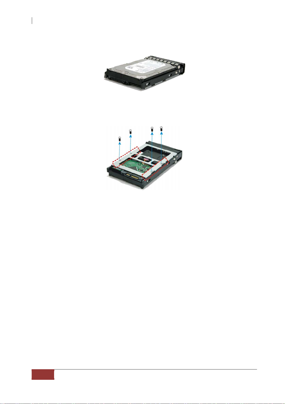
c. Place the hard drive in the disk tray.
d. Install the mounting screws on the bottom part to secure the drive in the disk
tray.
e. Slide the tray into a slot.
f. Close the lever handle until you hear the latch click into place.
26
User Manual
Page 27

USB and eSATA to SATA II RAID Subsystem
Chapter 3 RAID Configuration
The subsystem has a setup configuration utility built in containing important
information about the configuration as well as settings for various optional functions
in the subsystem. This chapter explains how to use and make changes to the setup
utility.
Configuration Methods
Ther e are thre e methods of confi guring th e subsys tem. You m ay config ure through
the following methods:
• VT100 terminal connected through the controller’s serial port
• Telnet via the R-Link Ethernet port
• Web browser-based Remote RAID man a gement via the R-Link Ethernet port
IMPORTANT! The subsystem allows you to access the utility using only
one method
same time.
at a time. You cannot use more than one method at the
3.1 Configuring Through a Terminal
Configuring through a terminal will allow you to use the same configuration options
and functions that are available from the LCD panel. To start-up:
1. Connect a VT100 compatible terminal or a PC operating in an equivalent ter m in a l
emulation mode to the monitor port located at the rear of the subsystem.
NOTE: You may connect a terminal while the subsystem’s power is on.
2. Power-on the terminal.
3. Run the VT100 program or an equivalent terminal program.
User Manual
27
Page 28

USB and eSATA to SATA II RAID Subsystem
4. The default setting of the monitor port is 115200 baud rate, 8 data bit,
parity, 1 stop bit and no flow control.
non-
28
User Manual
Page 29

5. Click disconnect button.
USB and eSATA to SATA II RAID Subsystem
6. Open the File menu, and then open Properties.
7. Open the Settings Tab.
User Manual
29
Page 30

USB and eSATA to SATA II RAID Subsystem
8. Configure the settings are follows:
“ Function, arrow and ctrl keys act as”: Terminal Keys
“ B ackspace key sends”: Crtl + H
“Emulation”: VT100
“Telnet terminal ID”: VT100
“Back scroll buffer lines”: 500
Click OK.
9. Now, the VT100 is ready to use. After you have finished the VT100 Terminal set u p ,
you may press t h e “X” key (in your Terminal) to link the RAID subsystem and
Ter minal together. Press “X” k ey to displa y the disk array Monitor Utility screen on
your VT100 Terminal.
10. The Main Me nu w il l appear.
Keyboard Function Key Definitions
“A” key - to move to the line above
“Z” key - to move to the next line
“Enter” key - Submit selection function
“ESC” key - Return to previous screen
“L” key - Line draw
“X” key – Redraw
User Manual
30
Page 31

USB and eSATA to SATA II RAID Subsystem
3.2 Main Menu
The main menu shows all function that enables the customer to execute actions by
clicking on the appropriat e link.
NOTE: The password option allows user to set or clear the RA I D
subsystem’s password protection feature. Once the password has
been set, the user can only monitor and configure the RAID
subsystem by providing the correct password. The password is
used to protect the RAID subsystem from unauthorized ac ce ss .
The controller will check the password only whe n entering the
Main menu from the initial screen. The RAID subsystem will
automatically go back to the initial screen when it does not
receive any command in twenty seconds. The RAID subsystem’s
factory default password is set to 00000000.
User Manual
31
Page 32

USB and eSATA to SATA II RAID Subsystem
VT100 terminal configuration Utility Main Menu Options
Select an option and the related information or submenu items display beneath it. The
submenus for each item are shown in th e n e x t S ection. The c on f i g u r at i o n
menu options are:
utility main
Menu Option Description
Quick Volume And Raid
Set Setup
Raid Set Functions
Volume Set Functions
Physical Drive Functions
Raid System Functions
Ethernet Configuration
Views System Events
Clear Event Buffer
Hardware Monitor
System Information
Create a RAID configuration which
consists of all physical disks installed
Create a customized Raid Set
Create a customized Volume Set
View individual disk information
Setting the Raid system configurations
Setting the Ethernet configurations
Record all system events in the buffer
Clear all event buffer information
Show all system environment status
View the controller information
32
User Manual
Page 33

USB and eSATA to SATA II RAID Subsystem
3.3 Menu Diagram
The following tree diagram is a summary of the various configurations and setting
functions that can be accessed through the terminal monitor.
User Manual
33
Page 34

USB and eSATA to SATA II RAID Subsystem
34
User Manual
Page 35

USB and eSATA to SATA II RAID Subsystem
User Manual
35
Page 36

USB and eSATA to SATA II RAID Subsystem
36
User Manual
Page 37

USB and eSATA to SATA II RAID Subsystem
User Manual
37
Page 38

USB and eSATA to SATA II RAID Subsystem
NOTE: This subsystem can c r e ate up to 16 Volume Sets which can be
mapped to eSATA Port0 or Port1, or USB Port.
can b e o v er 2 Terabytes. Use OS:
Windows Vista, Mac OS 10 or later, and Linux kernel 2.6 or later.
Windows 2003 SP1 or later,
The Volume Set size
38
User Manual
Page 39

USB and eSATA to SATA II RAID Subsystem
3.4 Web browser-based Remote RAID management via R-Link Port
The RAID subsystem can be configured with RAID Manager, a web browser-based
application which utilizes the web browser installed on your operating system. The web
browser-ba sed RAID Manager can be used to ma nage all the RAID function.
To configure the RAID subsyste m on a remote machine, you need to know its IP Addr ess.
Launch your web browser by entering http://[IP Address] in the remote web browser.
IMPORTANT! The d e fa u lt IP a dd re ss of R -L in k P or t is 192.168.1.100,
and subnet mask is 255.255.255.0. DHCP client function is also
enabled by default. You can r e configure the IP Address o r d i s a b l e
the DHCP client function through the LCD front panel or terminal
“Ethernet Configuration” menu.
NOTE: If DHCP client function is enabled but a DHCP server is
unavailable and the IP address is changed, a Controller Restart is
necessary. If the DHCP client function is disabled and the IP
address is changed, Controller Restart is not needed.
Note that you must be logged in as administrator with local admin rights on the remote
machine to remotely configure it. The RAID subsystem controller default User Name is
“admin” and the Password is “00000000”.
User Manual
39
Page 40

USB and eSATA to SATA II RAID Subsystem
Main Menu
The main menu shows all function that enables the user to execute actions by clicking
on the appropriate link.
Individual
Quick Function
Raid Set Functions
Volume Set
Functions
Physical Drives
System Controls
Information
Description
Create a RAID configuration, which consists
of all physical disks installed. The Volume
Set Capacity, Raid Level, and Stripe Size can
be modified during setup.
Create customized Raid Sets.
Create customized V olume Sets and allow
modification of parameters of existing Volume
Create pass through disks and allow
modification of parameters of existing pass
through drives. This also provides a function
to identify a respective disk drive.
For setting the RAID sys tem configurations.
To view the controller and hardware
mo ni to r information. The Raid Set hierarchy
can also be viewed through the Raid Set
Hierarchy item.
40
User Manual
Page 41

USB and eSATA to SATA II RAID Subsystem
Configuration Procedures
Below are a few practical examples of concrete configuration procedures.
3.5 Quick Create
The number of physical drives in the RAID subsystem determines the RAID levels
that can be implemented within the Raid S et. You can create a Raid S et associated
with exactly one V olume S et. The user can change the RAID level, Capacity, Volume
Initialization Mode and Stripe S ize. A hot spare option is also created depending upon
the existing configuration. Tick on the Confirm The Operation and click on the
Submit but ton in t he Quick Create screen, the Raid Set and Volume Set will s tart to
initialize.
If the Volume Se t size is over 2TB, an option “Greater Two TB Volume Support” will be
automatically provided in the screen as shown in the above example. There are two
options to select: “No” and “Yes”.
Greater Two TB Volume Support:
No: Volume Set capacity is set to maximum 2TB.
Yes: Volume Set capacity can be set o ve r 2TB.
NO T E: In Quick Create, the Raid S et is automatically configured based
on the number of disks in your system. Use the Raid Set Function and
Volume Set Function if you prefer to customize your Raid Set and
Volume Set.
NOTE: When Quick Create is used , the Vol ume Set will be mapped by
default to bot h h os t c h ann el s “ SATA&USB/0”. After the initialization is
done, please use the Modify Volume Set function to modify the host
ch annel as you need.
User Manual
41
Page 42

USB and eSATA to SATA II RAID Subsystem
3.6 Raid Set Functions
Use the Raid Set Function and Volume Set Function if you prefer to customize your
system. Use r c a n manually config ure and has full con trol of th e R aid S et a n d V o l u m e
Set setting, but it will take longer to set up than when using the Quick Create
fu n c t io n . Select the Raid Set Function to manu ally configure the R aid Set for t he firs t
time or to delete existing R aid Set and reconfigure a R aid Set. The maximum number
of RAID Sets that can be created depends on the number of disk channels in the
RAID subsystem. For 12 - bay RAID subsystem, twelve Raid Sets can be created.
3.6.1 Create Raid Set
To create a Raid S et, click on the Create Raid Set link. A “Select The IDE Drives
For RAID Set” screen is disp layed showing the IDE drives in the RAID subsy stem.
Check the “Select” option to include a physical drive to the current Raid Set. Enter
the p r ef e r r e d R a i d S e t N a m e ( 1 to 16 alphanumeric characters) to define a unique
identifier for the Raid Set. The default Raid Set name will always appear as Raid Set #
00 for first Raid Set.
Tick on the Confirm The Operation option and click on the Submit button in the
screen. The Raid Set will start to initialize.
42
User Manual
Page 43

USB and eSATA to SATA II RAID Subsystem
3.6.2 Delete Raid Set
To delete a Raid Set, click on the Delete Raid Set link. A “Select The RAID SET To Delete”
screen is displayed showing all Raid Sets existing in the current sub s ys t e m. Check the R aid Set
number you wa n t to delete in the Select column.
Tick on the Confirm The Operation option and click on the Submit button to process with
deletion.
User Manual
43
Page 44

USB and eSATA to SATA II RAID Subsystem
3.6.3 Expand Raid Set
Use this option to expand a R aid Set when o n e or m o r e disk drives is/are added to
the su bsystem. This function is active when at least one drive is availa ble.
To expand a Raid S et , click on the Expand Ra id Set link. Select th e Raid Set which you
want to expand.
Tick on the available disk(s) and check Confirm The Operation. C lick on the
button to add the select e d disk(s) to the Raid Set.
NOTE: Once the Expand Raid Set process has started, user
cannot stop it. The process must be completed.
NOTE: If a disk drive fails during Raid Set expansion and a hot
spare is available, an auto rebuild operation will occur after the
Raid Set ex pansion is completed.
Submit
44
User Manual
Page 45

USB and eSATA to SATA II RAID Subsystem
Migration occurs when a disk is added to a Raid S et. Migrating status is displayed in
the Raid Set status area of the Raid Set info rmation. Migrating status is also display ed in
the Volume Set status area of the Volume Set Information for all Volume Sets under the
Raid Set which is migrating.
User Manual
45
Page 46

USB and eSATA to SATA II RAID Subsystem
3.6.4 Offline Raid Set
If user wants to offline (and move) a Raid Set while the RAID subsystem is powered on,
use the Offline Raid Set function. After completing the function, the HDD state will
change to “Offlined” Mode.
To offline a Raid Set, click on the Offline Raid Set link. A “Select The RAID SET To
Offline” screen is displayed showing all existing Raid Sets in the subsystem. Select the
Raid Set which you want to offline in the Select column.
Tick on the Confirm The Operation, and then click on the Submit button to offline the
selected Raid Set.
NOTE: After completing the Offline Raid Set Function, all the LEDs of
the physical HDDs belonging to this Raid Set will be blinking red.
46
User Manual
Page 47

USB and eSATA to SATA II RAID Subsystem
3.6.5 Activate Incomplete Raid Set
When Raid Set State is “Normal”, this means there is no failed disk drive.
When does “Incomplete” Raid Set State Happens?
If the RAID subsystem is powered off and one disk drive is removed or has failed in
power off state, and when the RAID subsystem is powered on, the Raid Set State will
change to “Incomplete”.
The Volume Set will not be visible and the failed or removed disk will be shown as
“Missing”.
User Manual
47
Page 48

USB and eSATA to SATA II RAID Subsystem
When is the “Activate Raid Set” function can be used?
In order to access the Volume Set and corresponding data, use the Activate Raid Set
function to active the Raid Set. After selecting this function, the Raid State will
change to “Degraded” state.
To activate the incomplete the Raid Set, click on the Activate Raid Set link. A “Select
The Raid Set To Activate” screen is displayed showing all existing Raid S e ts in the
subsystem. Select the Raid Set wi t h “Incomplete” s ta t e which yo u wa n t to activate in the
Select column.
Click on the Submit button to activate the Raid Set. The Volume Set(s) associated
wit h t h e R a id S e t w i l l become accessible in “Degraded” mode.
NOTE: The “Activate Raid Set” function is only used when Raid Set
State is “Incomplete”. It cannot be used when Raid Set
configuration is lost. If ever the Raid Set configuration is lost,
please contact your vendor for support.
48
User Manual
Page 49

USB and eSATA to SATA II RAID Subsystem
3.6.6 Create Hot Spare
The Create Hot Spare option gives you the ability to define a global hot spare.
When you choose the Create Hot Spare option in the Raid Set Function, all unused
(non Raid Set member) disk drives in the subsystem appear. Select the target
disk drive by clicking on the appropriate check box. Tick on the Confirm The
Operation and click on the Submit button to create hot spare drive(s).
3.6.7 Delete Hot Spare
Use this option to remove the Hot Spare function from a disk drive.
Click the Delete Hot Spare function then select the Hot Spare Disk. Tick on the
Confirm The Operation, and clic k on the Submit button in the screen to delete the
hot spare disk.
User Manual
49
Page 50

USB and eSATA to SATA II RAID Subsystem
3.6 .8 Rescue Raid Set
If you need to rescue a missing Raid Set, please contact your vendor for sup port or
assistance.
50
User Manual
Page 51

USB and eSATA to SATA II RAID Subsystem
3.7 Volume Set Function
A Volume Set is seen by the host system as a single logical device. It is organized in a
RAID level with one or more physical disks. RAID level refers to the level of data
performance and protection of a Volume Set. A Volume Set capacity can consume all
or a portion of the r a w capacity available in a Raid Set.
Multiple Volume Sets can exist on a group of disks in a Raid Set. Additional Volume Sets
created in a specified Raid Set will reside on all the physical disks in the Raid Set. Thus
each Volume Set on the Raid Set will have its data spread evenly across all the disks in
the Raid Set.
3.7.1 Create Volume Set
The following are the Volume Set features:
1. Volume sets of different RAID levels may coexist on the same Raid Set.
2. Up to 16 Volume Sets in a Raid Set can be created by the RAID subsystem
controller.
To create Volume S et from a Raid Set, expand the Volume Set Functions in the main
menu and click on the Create Volume Set link. The Select The Raid Set To Create
Volume On It screen will show all existing Raid Sets. Tick on the Raid Set where
you want to create the Volume Set and then click on the Submit button.
Configure the Volume Set name, Capacity, RAID level, Stripe Size, Cache Mode,
Initialization Mode (if needed), SATA Data Xfer Mode, and
Channel/Drive#.
User Manual
51
Page 52

USB and eSATA to SATA II RAID Subsystem
Vo l um e N am e :
The default Volume Set name will always appear as Volume---VOL#00. You can rename
the Volume Set name provided it does not exceed the 16 characters limit.
Raid Level:
Set the RAID level for the Volume Set. Click the down-arrow in the drop- down list. The
available RAID levels for the current Volume Set are displayed. Select the preferred
RAID level.
Capacity:
The maximum Volume Set size is di sp l a ye d b y de f a ul t . If n e ce s s ar y , ch a n g e the
Volume Set size ap p ro p r ia t e fo r your a pplication.
Greater Two TB Volume Support:
If the Volume Se t size is over 2TB, an option “Greater Two TB Volume Support” will be
automatically provided in the screen as shown in the above example. There are two
options to select: “No” and “Yes”.
No: Volume Set capacity is set to maximum 2TB.
Yes: Volume Set capacity can be set o ve r 2TB.
Initialization Mode:
Set the Initializ ation Mode for the Volume Set. Fo reground mode is completed faster but
Volume Set but be completed before it becomes accessible. Background mode makes the
Volume Set available instantly but the initialization process takes longer.
Stripe Size:
This parameter sets the size of the stripe written to each disk in a RAID 0, 1, 10, an d 5
Volu me Set. You can set th e Stripe S ize to 4 KB, 8 K B, 16 KB, 3 2 KB, 64 KB, or 128 KB.
A larger Stripe Size produces better read performance, especially if the host server
does mostly sequential reads. However, if you are sure that the host server does
random reads more often, select a small Stripe Size.
52
User Manual
Page 53

USB and eSATA to SATA II RAID Subsystem
NOTE: Stripe Size in RAID level 3 can’t be modified.
Cache Mode:
The RAID subsystem supports Write-Through Cache and Write-Ba ck Cache.
SATA Data Xfer Mode
The RAID subsystem supports SATA150, SATA150+NCQ, SATA300, and
SATA300+NCQ data transfer mode.
Channel
Select the Host Channel for mapping the Volume Set. Options are: SATA (CH0), USBiA
(CH1), and SATA&USBiA.
NOTE: Select “SATA (CH0)” channel when Volume Set will be mapped
to eSATA Port0 or eSATA Port1. Select “USBiA (CH1)” channel when
Volume Set will be mapped to USB Port or accessed via iSCSI/AoE.
Drive #
For eSATA Port0, Drive # options are 0 to 7 (The drive# is assigned in order).
For eSATA Port1, Drive # options are 8 to 15 (Manual Assignment).
For USB Port, Drive # options are 0 to 7.
For iSCSI/AoE, Drive # options are 8 to 15.
NOTE: The eSATA HBA or controller in the host system must support
port multiplier to recognize Volume Sets mapped as Drives 1 to 7
and 8 to 15. Example of eSATA controllers that support port
multiplier are Sil3132 or 3124 and Intel ICH9 or ICH10.
Host Channel Port The Maximum Number of Volume Sets
eSATA Port0 8
eSATA Port1 8
USB 2.0 Port 8
iSCSI/AoE (R-Link Port) 8
IMPORTANT! It is not recommended to use iSCSI toge ther with
eSATA/USB at the same time since access to Volumes can be
slower than normal. Using eSATA and USB at the same time is ok.
NOTE: In order to maintain the system I/O performance, it is not
recommended to access the storage from the different host
interfaces at the same time.
User Manual
53
Page 54

USB and eSATA to SATA II RAID Subsystem
3.7.2 Delete Volume Set
To delete a Volume Set, select the Volume Set Functions in the main menu and click
on the Delete Volume Set link. The Select The Volume Set To Delete screen
will show all available Raid Sets. Tick on a Raid Set and check the Confirm The
Operation option and then click on the Submit button to show all Volume Sets in the
selected Raid S et. Tick on a Volume S e t a nd check t he Confirm The Operation
option. Click on the Submit button to
delete the Volume Set.
54
User Manual
Page 55

USB and eSATA to SATA II RAID Subsystem
3.7.3 Modify Volume Set
Use this function to modify Volume Set configuration.
To modify the attributes of a Vol ume S et:
1. Click on the Modify V olume Set link.
2. Tick f r o m t h e l i s t the Volume Set you want to modify. Click on the Submit button.
The following screen appears.
To modify Volume Set attribute values, select an attribute item and click on the attribute
value. After completing the modification, tick on the Confirm The Operation option and
click on the Submit button to save the changes.
User Manual
55
Page 56

USB and eSATA to SATA II RAID Subsystem
3.7.3.1 Volume Expansion
Volume Capacity (Logical V olume Concatenation Plus Re-stripe)
Use the Expand Raid Set function to expand a Raid Set when a disk is added to your
subsystem. (Refer to Section 3.6.3)
The expanded capac ity can be used to enlarge the V o lume S e t size or cr eate another
Volume Set. Use the Modify Volume Set function to expand the Volume Set capacity.
Select the Volume Set and move the cursor to the Volume Set Capacity it em and enter
the ca pacity size.
NOTE: Only the last created Volume Set can be expanded.
Tick on t he Confirm The Opera tion and click on the Submit button to complete the
action. The Volume Set starts to expand.
3.7.4 Volume Set Migration
Migration occurs when a Volume Set migrates f rom one RAID level to ano ther, a
Volume Set stripe size changes, or when a disk is added to a Raid Set. Migrating
status is displayed in the Volume Set status area of the RaidSet Hierarchy screen
during migration.
56
User Manual
Page 57

USB and eSATA to SATA II RAID Subsystem
3.7.5 Check Volume Set
Use this function to perform Volume Set consistency check, which verifies the correctness
of redundant data (data blocks and parity blocks) in a Volume Set. This basically means
computing the parity from the data blocks and comparing th e results to the contents of
the parity blocks, or computing the data from the parity blocks and comparing the
results to the contents of the data blocks.
To perform Check Volume Set function:
1. Click on the Check Volume Set link.
2. Tick from the list the Volume Set you want to check. Tick on Confirm The
Operation and click on the Submit button. The Checking process will be started.
Check Volume Set Options:
Scrub Bad Block If Bad Block Found, Assume Parity Data is Good
Re-compute Parity if Parity Error, Assume Data is Good
NOTE: When the 2 options a re not sele cted, it will only check for
errors. It is recommended to perform Check Volume Set with the
2 options unselected at first. If the resu lt shows erro rs, the data
must be backed up to a safe storage. Then the two options can
be selected and redo Check Volume Set to cor rect the errors.
User Manual
57
Page 58

USB and eSATA to SATA II RAID Subsystem
The checking percentage can also be viewed by clicking on RaidSet Hierarchy in the
main menu.
3.7.6 Stop Volume Set Check
Use this option to stop the current running Check Volume Set process.
58
User Manual
Page 59

USB and eSATA to SATA II RAID Subsystem
3.8 Physical Drive
Choose this option from the Main Menu to select a disk drive and to perform the
operations listed below.
3.8.1 Create Pass-Through Disk
A Pass-Through Disk is a disk drive not controlled by the internal RAID subsystem
firmware and thus cannot be a part of a Volume Set. A Pass-Through disk is a
se p ar a t e a n d i n d iv i d ua l R a id S et . The disk is available to the ho st as an individual disk.
It is typically used on a system where the operating system is on a disk not controlled
by the RAID firmware.
To create pass-through disk, click on the Create Pass-Through link under the
Physical Drives main menu. The setti ng fun ction scree n appears.
Select the disk drive to be made as Pass-Through Disk and configure the Pa ss-Through
Disk attributes, such as the Cache Mode, SATA Data Xfer Mode and Channel: Drive#
for this volume.
User Manual
59
Page 60

USB and eSATA to SATA II RAID Subsystem
3.8.2 Modify Pass-Through Disk
Use this option to modify the Pass-Through Disk attributes. User can modify the Cache
Mode, SATA Data Xfer Mode and Channel:Drive#.
To modify the Pass-Through drive attribute from the Pass-Through drive pool, click
on the Modify Pass-Through link. The “Select The Pass-Through Disk For
Modification” screen appears. Tick on the Pass-Through Disk from the Pass-Through
drive pool and click on the Submit button to select the drive.
The Ent er Pass-Thr ough Disk Attribu te screen a ppears. M od ify the dri ve attribute
values as you want.
To save changes, tick on Confirm The Operation and click on the Submit button.
60
User Manual
Page 61

USB and eSATA to SATA II RAID Subsystem
3.8.3 Delete Pass-Through Disk
To delete Pass-Through Disk from the Pass-Through drive pool, click on Delete PassThrough link. Select a Pass-Through Disk, tick on the Confirm The Operation and
click the Submit button to complete the delete action.
3.8.4 Identify Selected Drive
Use this option to physically locate a selected drive to prevent removing the wrong drive.
When a disk drive is selected using the Identify Drive function, the LED of the selected
disk drive will light.
To identify a selected drive from the drives pool, click on the Identify Drive link. The
“Select The IDE Drive For identification” screen appears. Tick on the disk drive from the
drives list. After completing the selection, click on the Submit button to identify
selected drive.
User Manual
61
Page 62

USB and eSATA to SATA II RAID Subsystem
3.9 System Controls
3.9.1 System Configuration
To set the RAID subsystem system configuration options, click the System
Config link under the System Controls menu. The System Configuration
screen will be shown. Set the system configuration option as needed.
System Beeper Setting:
This option is used to Disabled or Enable the su b s y s t em ’ s RAID controller alarm beeper.
Background Task Priority:
The Background Task Priority indica tes how much t ime and system resource the RAID
controller devotes to a background task, such as a rebuild operation. The RAID
subsystem allows user to choose the ba ck g rou nd tas k priorit y (High 80 %, Med iu m 50% ,
Low 25%, and Ultra Low 5%) to balance between background task process and
V olume S et access. For hi gh R A I D s u b s y s t e m per formanc e, speci fy a low value.
Terminal Port Configuration:
Baud Rate setting values are 1200, 2400, 4800, 9600, 19200, 38400, 57600, and
115200. Use 115200 for the RAID subsystem terminal port speed setting.
Stop Bits values are 1 bit and 2 bits. Use 1 bit for the RAID subsystem stop bit
setting.
Note: Parity value is fixed at “None”. Data Bits value is fixed at 8 bits.
62
User Manual
Page 63

USB and eSATA to SATA II RAID Subsystem
JBOD/RAID Configuration
The RAID subsystem supports JBOD and RAID configuration.
Maximum SATA Mode Supported:
The 12 SATA drive channel can support up to SATA ll, which runs up to 300MB/s. NCQ is a
command protocol in Serial ATA that can only be implem ented on native S eri al ATA h ard
drives. It allows multiple commands to be outstanding within a drive at the same time.
Drives that support NCQ have an internal queue where outstanding commands can be
dynamically rescheduled or re-ordered, along with the necessary tracking mechanisms for
outstanding and completed portions of the workload. RAID subsystem allows user to
choose the SATA Mode: SA TA150, SA T150+NCQ, SAT300, SAT A300+NCQ.
Host NCQ Mode Setting:
This option allows the users to se l e c t th e s u p p o rt e d Host NCQ Mode or to disable it.
Options are: ESB2/MACPro/SiliconImage, Marvell 6145, ICH, nVidia, and D isabled.
HDD Read Ahead Cache:
This option allows the users to disable the cache of the disk drives in the RAID
subsystem. In some HDD models, disabling the cache in the HDD is necessary to
prove the RAID subsystem functions correctly.
Volume Data Read Ahead:
This option allows the users to s et t h e Volume Data Read Ahead function. Optio ns
are: Normal, Aggressive, Conservative, and Disabled.
Stagger Power On Control:
This option allows the RAID subsystem’s power supply to power up in succession
each HDD in the RAID subsystem. In the past, all the HDDs on the RAID subsystem
are powered up altogether at the same time. This function allows the power
transfer time (lag time) from the last HDD to the next one be set within the range of
0.4 to 6.0 seconds.
Spin Down Idle HDD (Minutes): MAID Function
This option enables the hard drives to spin down after they become idle after a preset
period of time. Options are: Disabled, 1 (For Test), 3, 5, 10, 15, 20, 30, 40, and 60.
Empty HDD Slot LED:
Use this option to turn ON or OFF the LED of a slot with no HDD.
HDD SMART Status Polling:
The RAID subsystem can read HDD SMART information through this function. This
function is enabled by default.
User Manual
63
Page 64

USB and eSATA to SATA II RAID Subsystem
Auto Activate Incomplete Raid:
Use this option to automatically activate an Incomplete Raid Set. Note that the Raid Set
status becomes Incomplete when one disk is removed or failed in power off state. After
activated, the Volume Set(s) in the Raid Set will be in Degraded mode.
Disk Capacity Truncation Mode:
This RAID subsystem use drive truncation so that drives from different vendors are
more likely to be able to be used as spares for each other. Drive truncation slightly
decreases the usable capacity of a drive that is used in redundant units. Options are:
Multiples Of 10G: If you have several 120GB drives from different vendors,
chances are that the capacity varies slightly. For example, one drive might be
121.1 GB, and the other 120.4 GB. This drive truncation mode makes the
121.1 GB and 120.4 GB drives same capacity as 120 GB so that one could
replace the other.
Multiples Of 1G: If you have 120 GB drives from different vendors, chances are
that the capacity varies slightly. For example, one drive might be 121.1 GB, and
the other 121.4 GB. This drive truncation mode makes the 121.1 GB and 121 .4
GB drives same capacity 121 GB so that one could replace the other.
No Truncation: The capacity of the disk drive is not truncated .
64
User Manual
Page 65

USB and eSATA to SATA II RAID Subsystem
3.9. 2 iSCSI Configuration
To set the iSCSI Configuration options, click the iSCSI Config link under th e
System Controls men u. The i S C S I Configuration sc r e e n will be shown. Set the
system configuration option as needed.
iSCSI TargetNode Base Name
This option is used to set the iSCSI target node base name.
iSCSI Port Number (7168..8191 Is Reserved)
This option is used to modify the iSCSI port number to be used in iSCSI connection.
Note that port numbers from 7168 to 81 91 cannot be used. Port Number can also be
changed in EhterNet Config.
NOTE: The new settings wil l take effect o nly after nex t volume
change/login.
User Manual
65
Page 66

USB and eSATA to SATA II RAID Subsystem
3.9.3 EtherNet Config
To set the Ethernet c o n f i g u r a t i o n , click the EtherNet Config link under the System
Controls menu. The RAID subsystem EtherNet Configuration screen will be shown. Set
the desired configuration. Once done, tick on the Confirm The Operation and click the
Submit button to save the settings.
DHCP Function
This option is used to disable or enable (Default is Enabled) the DHCP client function.
Local IP Address
This option is used to configure the R-Link IP address, if DHCP is disabled.
Gateway IP Address
This option is used to configure the R-Link IP gateway IP address, if DHCP is disabled.
Subnet Mask
This option is used to configure the subnet mask, if DHCP is disabled.
HTTP Port Number
This option is used to set HTTP Port Number. Default is 80. Note that port number from
7168 to 8191 is reserved for system use.
66
User Manual
Page 67

USB and eSATA to SATA II RAID Subsystem
Telnet Port Number
This option is used to set Telnet Port Number. Default is 23. Not e that port number
from 7168 to 8191 is reserved for system use.
SMTP Port Number
This option is used to set SMTP Port Number. Default is 25. Note that port number from
7168 to 8191 is reserved for system use.
iSCSI Port Number
This option is used to set iSCSI Port Number. Default is 3260. Port Number can also be
changed in iSCSI Config. Note that port number from 7168 to 8191 is reserved for
system use.
AoE Major Address
This option is used to set the AoE Header Major Address. Range is from 0 to 4 094.
User Manual
67
Page 68

USB and eSATA to SATA II RAID Subsystem
3.9.4 Alert By Mail Config
To set the Event Notification function, click on the Alert By Mail Config link under the
System Controls main menu. The RAID subsystem Event Notification configuration screen
will be shown. Set up the desired function and option. When an abnormal condition
occurs, an error message will be emailed to the email recipient(s) that a problem has
occurred. Events are classifi ed in to 4 levels ( Urgent, Serious, Warning, and Information).
68
User Manual
Page 69

USB and eSATA to SATA II RAID Subsystem
3.9.5 SNMP Configuration
The SNMP gives users independence from the proprietary network management schemes
of some manufacturers and SNMP is supported by many WAN and LAN manufacturers
enabling true LAN/ WAN ma nage ment integration.
To set the SNMP function, move the cursor to the main menu and click on the
SNMP Configuration li n k. The RAID subsystem’s SNMP Configurations screen
will be shown. Select the desired function and set the preferred option.
SNMP Trap Configurations: Type the SNMP Trap IP Address. The SN MP Port is set to
162 by default.
SNMP System Configuration:
Community: The default is Public.
(1)sysContact.0; (2)sysLocation.0; (3)sysName.0: SNMP parameter (31 bytes max). If
these 3 categor ies are configu red and when an error occu rs, S NMP w il l sen d ou t a
message that includes the 3 categories within the message. This allows user to easily
define which RAID unit is having problem.
SNMP Trap Notification Configurations: Select the desired option.
After completing the settings, tick on the Confirm The Operation and click on the
Submit button to save the configuration.
SNMP also works in the same as Alert By Mail when sending event notifications.
User Manual
69
Page 70

USB and eSATA to SATA II RAID Subsystem
3.9. 6 NTP Configuration
NTP stands for Network Time Protocol. It is an Internet protocol used to synchronize
the clocks of computers to some time reference. Type the NTP Server IP Address to
enable the RAID subsystem to synchronize with it.
To set the NTP function, move the cursor to the main menu and click on the NTP
Configuration. The RAID subsyst em’s NTP Configuration screen will be displayed
Select the desired function and configure the necessary option.
After completing the settings, tick on the Confirm The Operation and click on the
Submit button to save the configuration.
.
70
User Manual
Page 71

USB and eSATA to SATA II RAID Subsystem
3.9.7 View Events/Mute Beeper
To view the RAID subsystem’s event log information, mov e the mous e curs or t o the
System Controls menu and click on the System Information link. The Raid Subsystem’s
System Events Information screen a ppear s.
The System Events Information screen will show: Time, Device, Event type, Elapse
Time and Errors. The RAID system does not have built-in real time clock. When th e
RAID manager GUI is opened f rom a host system v ia R-L ink c onnection, th e RA ID
system’s time will be referenced to the time of the host system. When not connected to
the RAID Manager GUI via R-Link conn ection, th e ti me inf ormat ion is the re lative t o the
time when the RAID subsystem was powered on.
This function can also be used to silence the alarm beeper.
User Manual
71
Page 72

USB and eSATA to SATA II RAID Subsystem
3.9.8 Generate Test Event
If you want to generate test events, move the mouse cursor to the main menu and
click on the Generate Test Events Link. Tick on the Confirm The Operation and
click on the Submit button. Then click
the test event.
on the View Events/Mute Beeper to view
72
User Manual
Page 73

USB and eSATA to SATA II RAID Subsystem
3.9.9 Clear Event Buffer
Use this feature to clear the RAID subsystem’s System Events Information buffer.
User Manual
73
Page 74

USB and eSATA to SATA II RAID Subsystem
3.9.10 Modify Password
To change or disable the RAID subsystem’s admin password, click on the Change
Password link under the System Controls menu. The Modify System Password screen
appears.
The factory-default admin password is set to 00000000. Once the password has been set,
the user or administrator can only monitor and configure the RAID subsystem by
providing the correct password.
The password is used to protect the RAID subsystem’s configuration from unauthorized
access. The RAID controller will check the password only when entering the Main Menu
from the initial screen. The RAID subsystem will aut omatically go back to the initial
screen when it does not receive any command after sometime.
To disable the password, enter only the original password in the Enter Original
Password box, leave both the Enter New Password and Re-Enter New Password
boxes blank. After selecting the Confirm The Operation option and clicking the
Submit button, the system password checking will be disabled. No password checking
will occur when entering the main menu from the starting screen.
3.9.11 Upgrade Firmware
Please refer to Section 3.12 for more information.
74
User Manual
Page 75

USB and eSATA to SATA II RAID Subsystem
3.9.12 Shutdown Controller
Use this function to shutdown the RAID Controller. This is used to flush the data from the
cache memory, and is normally done before powering off the subsystem .
3.9.13 Restart Controller
Use this function to restart the RAID controller.
User Manual
75
Page 76

USB and eSATA to SATA II RAID Subsystem
3.10 Information Menu
3.10.1 RaidSet Hierarchy
Use this feature to view the RAID subsystem’s existin g Raid Set(s), Volume Set(s)
and physical disk(s) configuration and information. Select the RaidSet Hierarchy
link from the Information menu to display the Raid Set Hierarchy screen..
To view the Raid Set inform ation, click the Raid Set # link from the Raid Set
Hierarchy screen. The Raid Set Information screen appears.
76
User Manual
Page 77

USB and eSATA to SATA II RAID Subsystem
To view the disk drive information, click the CH0# link from the Raid Set
Hierarchy screen. The Disk Information screen appears. This screen shows
various information such as timeout count, media error count, and SMART
information.
The SMART information shows two numbers, one on the left (attribute value)
and one on the right enclosed in parentheses (threshold). The higher the attribute
value is compared to the threshold value, the better. If the attribute value becomes
smaller than the threshold value, the disk is in unstable state.
To view the Volume Set in formation, click the Volume Set # link from the Raid Set
Hierarchy screen. The V olume Set Information screen appears.
User Manual
77
Page 78

USB and eSATA to SATA II RAID Subsystem
3.10.2 System Information
To view the RAID subsystem’s controller information, click the System Information link
from the Information menu. The Raid Subsystem Information screen appears.
The controller name, firmware version, serial number, main processor, CPU data/instruction
cache size and system memory size/speed appear in this screen.
78
User Manual
Page 79

USB and eSATA to SATA II RAID Subsystem
3.10.3 Hardware Monitor
To view the RAID subsystem’s controller hardware information, click the Hardware
Monitor link from the Information menu. The Hardware Monitor Information screen
appears.
NOTE: When no disk drive is installed in the disk slot, the disk
temperature will show “--”. The disk temperature will also show “-” when “HDD SMART Status Polling” is disabled in System
Configuration.
The Hardware Monitor Information provides the temperature and voltage levels of the
RAID subsystem. All items are also unchangeable. When the threshold values are
exceeded, warning messages will be indicated through the LCD, LED and alarm buzzer .
Item
Controller Board Temperature
HDD T emperature
Power Supply +12V
Power Supply +5V
Power Supply +3.3V
Warning Condition
> 60 Celsius
> 60 Celsius
< 10.5V or > 13.5V
< 4.7V or > 5.4V
< 3.0V or > 3.6V
DDR Supply V ol tage +2.5V
CPU Core Voltage +1.3V
DDR Termination Power +1.25V
< 2.25V or > 2.75V
< 1.17V or > 1.43V
< 1.125V or > 1.375V
User Manual
79
Page 80

5
USB and eSATA to SATA II RAID Subsystem
3.11 Creating New Raid Set or Reconfiguring an Existing Raid Set
You can configure Raid Sets and Volume Sets using Quick Create or Raid Set
Functions/Volume Set Functions configuration method. Each configuration method
requires a different level of user input. The general flow of operations for Raid Set and
Volume Set configuration is:
Step Action
1 Designate hot spare d i sk/pa ss-through d i s k (optional).
2 Choose a configuration method.
3 Create Raid Set using the available physical drives.
4 Define Volume Set using the available raw capacity in the Raid
Initialize the Volume Set. Then use Volume Set in the Host OS.
80
User Manual
Page 81

USB and eSATA to SATA II RAID Subsystem
3.12 Upgra ding the Firmware
Upgrading Firmware Using Flash Programming Utility
Since the RAID subsystem’s controller features flash firmware, it is not necessary to
change the hardware flash chip in order to upgrade the controller firmware. User can
simply re-program the old firmware through the RS-232 port. New releases of the
firmware are available in the form of binary fil e a t ve n do r ’ s F T P. T he file available at the
FTP site is usually a self-extracting file that contains the following:
XXXXVVV.BIN Firmware Binary (where “XXXX” refers to the model name and
“VVV” refers to the firmware version)
README.TXT It contains the history information of the firmware change. Read this file
first before upgrading the firmware.
These files must be extracted from the compressed file and copied to one directory in the
host computer.
Establishing the Connection for the RS-232
The firmware can be downloaded to the RAID subsystem’s controller using an ANSI /VT-
100 compatible terminal emulation program or web browser-based RAID Manager
remote management page.
With terminal emulation program, you must complete the appropriate installation and
configuration procedure before proceeding with the firmware upgrade. Whichever
terminal emulation program is used must support the ZMODEM file transfer protocol.
Web browser-based RAID Manager can be used to update the firmware. A web browser
must have been installed and setup before proceeding with the firmware upgrade.
User Manual
81
Page 82

USB and eSATA to SATA II RAID Subsystem
Upgrading Firmware Through ANSI/VT-100 Terminal Emulation
Get the new firmware vers i o n for your RAID sub system controller. For Example, download
the bin file from your vendor’s web site into the local directory.
NOTE: When there is new boot ROM firmware that needs to be
upgraded, upgrade first the boot ROM firmware. Then repeat the
process (steps 1 to 9) to upgrade the firmware code after which a
RAID controller restart will be necessary.
1. From the Main Menu, scroll down to “Raid System Function”
2. Choose the “Update Firmware”. The Update The Raid Firmware dialog box appears.
3. Go to the menu bar and click Transfer. Select Send File.
82
User Manual
Page 83

USB and eSATA to SATA II RAID Subsystem
4. Select “ZMODEM modem” under Protocol to set ZMODEM as the file transfer protocol of
your terminal emulation software.
5. Click Browse. Look in the location where the firm ware file w a s sa v e d . Select the
firmware file name “xxxxxxxx.BIN” and click O pen.
6. Click Send to send the firmware binary file to the RAID controller.
User Manual
83
Page 84

USB and eSATA to SATA II RAID Subsystem
7. When the firmware downloading is completed, the confirmation screen appears.
Select Yes to start programming the flash ROM.
8. When the Flash programming starts, a message will show “ Start Updating Firmware.
Please Wait”.
9. The firmware upgrade will take approximately thirty seconds to complete.
84
User Manual
Page 85

USB and eSATA to SATA II RAID Subsystem
10. After the f irmware upgrade is co mplete, a message will show “Firmware
Updated Successfully”. Restarting the RAID controller is required for the new firmware
to take effect.
Has Been
User Manual
85
Page 86

USB and eSATA to SATA II RAID Subsystem
Upgrading Firmware Through Web Browser
Get the new version of firmware for your RAID subsystem controller.
NOTE: When there is new boot ROM firmware that needs to be
upgraded, upgrade first the boot ROM firmware. Then repeat the
process (steps 1 to 3) to upgrade the firmware code after which a
RAID controller restart will be necessary.
1. To upgrade the RAID subsystem firmware, click the Upgrade Firmware link under
System Controls menu. The Upgrade The Raid System Firmware Or Boot Rom screen
appears.
2. Click Browse. Look in the location wh ere the f irmw are file wa s s a v ed . Select the
firmware file name “xxxxxxxx.BIN” and click Open.
3. Select the Confirm The Operation option. Click the Submit button.
4. The Web Browser begins to download the firmware binary to the controller and start
to update the flash ROM.
5. After the firmware upgrade is complete, a message will show “Firmware
Updated Successfully”. Restarting the RAID controller is required for the new firmware
to take effect.
86
User Manual
Has Been
 Loading...