

Page 1

8-Port 10/100Mbps 802.3af / 802.3at PoE +
1-Port 10/100/1000Mbps Desktop Switch
FGSD-910P / FGSD-910HP
User’s Manual
Page 2

Trademarks
Copyright © PLANET Technology Corp. 2014.
Contents are subject to revision without prior notice.
PLANET is a registered trademark of PLANET Technology Corp. All other trademarks
belong to their respective owners.
Disclaimer
PLANET Technology does not warrant that the hardware will work properly in all
environments and applications, and makes no warranty and representation, either
implied or expressed, with respect to the quality, performance, merchantability, or
tness for a particular purpose.
PLANET has made every effort to ensure that this User’s Manual is accurate;
PLANET disclaims liability for any inaccuracies or omissions that may have
occurred.
Information in this User’s Manual is subject to change without notice and does not
represent a commitment on the part of PLANET. PLANET assumes no responsibility
for any inaccuracies that may be contained in this User’s Manual. PLANET makes
no commitment to update or keep current the information in this User’s Manual,
and reserves the right to make improvements to this User’s Manual and/or to the
products described in this User’s Manual, at any time without notice.
If you nd information in this manual that is incorrect, misleading, or incomplete,
we would appreciate your comments and suggestions.
FCC Warning
This equipment has been tested and found to comply with the limits for a Class A
digital device, pursuant to Part 15 of the FCC Rules. These limits are designed to
provide reasonable protection against harmful interference when the equipment is
operated in a commercial environment. This equipment generates, uses, and can
radiate radio frequency energy and, if not installed and used in accordance with
the Instruction manual, may cause harmful interference to radio communications.
Operation of this equipment in a residential area is likely to cause harmful
interference in which case the user will be required to correct the interference at
his own expense.
Page 3

CE Mark Warning
This is a Class A product. In a domestic environment, this product may cause radio
interference, in which case the user may be required to take adequate measures.
Energy Saving Note of the Device
This power required device does not support Standby mode operation.
For energy saving, please remove the power cable to disconnect the device from
the power circuit.
Without removing power cable, the device will still consuming power from the
power source. In the view of Saving the Energy and reduce the unnecessary power
consuming, it is strongly suggested to remove the power connection for the device
if this device is not intended to be active.
WEEE Warning
To avoid the potential effects on the environment and human health as a
result of the presence of hazardous substances in electrical and electronic
equipment, end users of electrical and electronic equipment should
understand the meaning of the crossed-out wheeled bin symbol. Do not
dispose of WEEE as unsorted municipal waste; WEEE has to be collected
separately.
Revision
PLANET 8-Port 10/100Mbps 802.3af / 802.3at PoE + 1-Port 10/100/1000Mbps
Desktop Switch User's Manual
For Models: FGSD-910P / FGSD-910HP
Revision: 1.1 (MARCH, 2014)
Part No.: 2351-AK3140-002
Page 4

Table Of Contents
1. Introduction ............................................................................................... 5
1.1 Checklist ............................................................................................. 5
1.2 Product Description .............................................................................. 5
1.3 Features ............................................................................................. 6
1.4 Specications ...................................................................................... 7
2. Hardware Description .................................................................................. 9
2.1 Front Panel ......................................................................................... 9
2.1.1 LED Indicators ........................................................................... 9
2.2 Rear Panel .........................................................................................10
2.3 Desktop Installation ............................................................................ 12
2.4 Rack Mounting ...................................................................................13
2.5 Product Application ............................................................................. 14
2.5.1 802.3af PoE IP Surveillance in Public Transportation .....................14
2.5.2 IP Ofce Department / Workgroup PoE Switch .............................16
2.6 Power over Ethernet Powered Device ...................................................17
3. Power over Ethernet Overview ....................................................................18
4. Troubleshooting .........................................................................................21
Appendix: A Networking Connection .................................................................22
A.1 PoE RJ-45 Port Pin Assignments ...........................................................22
A.2 Switch's Data RJ-45 Pin Assignments - 1000Mbps, 1000Base-T ..............22
A.3 10/100Mbps, 10/100Base-TX ...............................................................23
Page 5

1. Introduction
1.1 Checklist
Check the contents of your package for the following parts:
z FGSD-910P / FGSD-910HP x 1
z User's Manual x 1
z Power Cord x 1
z Two 19” Rack-mounting Brackets with Attachment Screws x 8
If any of these pieces are missing or damaged, please contact your dealer
immediately; if possible, retain the carton including the original packing material,
and use them again to repack the product in case there is a need to return it to us
for repair.
The term “PoE Ethernet Switch” mentioned in this user’s manual also means the
FGSD-910P / FGSD-910HP.
1.2 Product Description
Centralized Power Distribution for Ethernet Networking
The FGSD-910P / FGSD-910HP, a new member in the PLANET 802.3af / 802.3at
PoE Fast Ethernet Switch family, is an 8-port 10/100Mbps 802.3af / 802.3at
Power over Ethernet + 1-Gigabit Port Switch with a total of 120 watts of PoE
budget, which is an ideal solution to fullling the demand of sufcient PoE power
for network applications with Fast Ethernet speed transmission. The eight 802.3af /
802.3at PoE ports provides PoE power injector function which is able to drive 8
IEEE 802.3af compliant powered devices or 3 IEEE 802.3at compliant powered
devices (FGSD-910HP only). The FGSD-910P / FGSD-910HP also provides a simple,
cost-effective and non-blocking wire-speed performance. It comes with a 12-
inch metal compact housing, suitable for desktop deployment in SOHO ofce or
department network application.
Perfectly Integrated Solution for IP PoE Camera and NVR System
Different from the general IT industrial PoE Switch which usually comes with 12 or
24 PoE ports, the FGSD-910P / FGSD-910HP provides eight 802.3af / 802.3at PoE
ports for catering to small scale of IP Surveillance networks at a lower total cost.
The FGSD-910P / FGSD-910HP comes with high performance switch architecture
and 120-watt PoE power budget. The recorded video les from 8 PoE IP Cameras
can be powered by the FGSD-910P / FGSD-910HP and saved in the 8-channel NVR
system or surveillance software to perform comprehensive security monitoring. For
instance, one FGSD-910P / FGSD-910HP can be combined with one 8-channel NVR
and 8 PoE IP camera as a kit for the administrators to centrally and efciently
manage the surveillance system in the local LAN and the remote site via Internet.
5
Page 6

Easy Cable Connection
With data and power over Ethernet from one unit, the FGSD-910P / FGSD-910HP
reduces cabling requirements and eliminates the need for dedicated electrical
outlets on the wall, ceiling or any unreachable place. A wire that carries both
data and power can lower the installation costs, simplify the installation effort and
eliminate the need for electricians or extension cords. Providing 8 PoE interfaces,
the FGSD-910P / FGSD-910HP is ideal for small businesses and workgroups
requiring deploying the PoE for the wireless access points, IP-based surveillance
camera or IP phones in any places easily, efciently and cost-effectively.
1.3 Features
RJ-45 Interface
8-Port 10/100Mbps Fast Ethernet Switch
8-Port supports 48V DC power to PoE Powered Device (FGSD-910P)
8-Port supports 56V DC power to PoE Powered Device (FGSD-910HP)
1-Port 10/100/1000Mbps Gigabit Ethernet Switch
Power over Ethernet
Complies with IEEE 802.3af / 802.3at Power over Ethernet End-Span PSE
Up to 8 IEEE 802.3af devices powered
Supports PoE Power up to 15.4 watts for each PoE port
Up to 3 IEEE 802.3at devices powered (FGSD-910HP only)
Supports PoE Power up to 30 watts for each PoE port (FGSD-910HP only)
120-watt PoE budget
Auto detects powered device (PD)
Circuit protection prevents power interference between ports
Remote power feeding up to 100m
6
Page 7

Switching
Hardware based 10/100Mbps Auto-Negotiation and Auto MDI/MDI-X (Port 1 to
Port 8)
Hardware based 10/100/1000Mbps Auto-Negotiation and Auto MDI/MDI-X
(Port 9)
Flow control for Full Duplex operation and back pressure for Half Duplex
operation
Integrates address look-up engine, supporting 4K absolute MAC addresses
Automatic address learning and address aging
Hardware
12-inch desktop size, 1U height
LED indicators for system power, per port PoE ready and PoE activity, speed,
Link / Act
1 silent fan to provide stable and efcient power performance
1.4 Specications
Model FGSD-910P FGSD-910HP
Hardware Specications
Network Connector
PoE Inject Port
LED Display
Switch Architecture Store and Forward switch architecture
MAC Address Table 4K MAC address table with auto learning function
Switch Fabric 3.6Gbps
Switch Throughput 2.67Mpps@64Bytes
Flow Control
8-Port RJ-45 for 10/100Base-TX (Port 1 to Port 8)
1-Port RJ-45 for 10/100/1000Base-T (Port 9)
8-Port with 802.3af PoE
injector function
System: Power (Green)
Per PoE port: PoE (Orange)
LNK/ACT (Green)
Gigabit port: Speed (Green)
LNK/ACT (Green)
Back pressure for Half-Duplex. IEEE 802.3x Pause
Frame for Full-Duplex
8-Port with 802.3at PoE
injector function
7
Page 8

Power Requirements
Power Consumption 130 watts / 443BTU
Dimensions (W x D x H) 280 x 180 x 43mm, 1U height
Weight 1.7kg
Power over Ethernet
PoE Standard
PoE Power Supply Type End-Span End-Span
PoE Power Output
Power Pin Assignment 1/2(+), 3/6(-) 1/2(+), 3/6(-)
PoE Power Budget
Max. Number of Class 1 PD 8 8
Max. Number of Class 2 PD 8 8
Max. Number of Class 3 PD 8 8
Max. Number of Class 4 PD - 3
Standard Conformance
EMI Safety FCC Class A, CE
Operating Environment 0 ~ 50 degrees C
Storage Environment -10 ~ 70 degrees C
Operating Humidity 5 ~ 95%, Relative Humidity, non-condensing
Storage Humidity 5 ~ 95%, Relative Humidity, non-condensing
Standard Compliance
* Remarks: POE Power budget may be reduced if the operating temperature rises.
AC 100~240V, 50/60Hz,
2A max.
IEEE 802.3af Power over
Ethernet / PSE
Per Port 48V DC,
350mA. Max. 15.4 watts
120 watts (at room
temperature)*
IEEE 802.3
IEEE 802.3u
IEEE 802.3ab
IEEE 802.3x
IEEE 802.3af
IEEE 802.3at
Ethernet
Fast Ethernet
Gigabit Ethernet
Flow Control
Power over Ethernet
High Power over Ethernet (FGSD910HP only)
AC 100~240V, 50/60Hz,
2.5A max.
IEEE 802.3at Power over
Ethernet / PSE
Per Port 56V DC,
600mA. Max. 30 watts
120 watts (at room
temperature)*
8
Page 9
2. Hardware Description
This product provides three different running speeds – 10Mbps and 100Mbps at
port 1 to port 8, 10/100/1000Mbps at port 9 and automatically distinguishes the
speed of incoming connection.
This section describes the hardware features of the FGSD-910P / FGSD-910HP. For
easier management and control of the switch, familiarize yourself with its display
indicators, and ports. Front panel illustrations in this chapter display the unit LED
indicators. Before connecting any network device to the FGSD-910P / FGSD-910HP,
please read this chapter carefully.
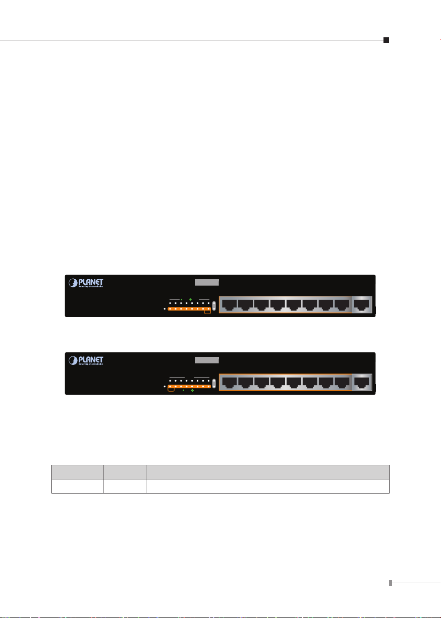
2.1 Front Panel
The Front Panel of the FGSD-910P / FGSD-910HP PoE Ethernet Switch consists
of 8x Auto-Sensing 10/100Mbps Ethernet RJ-45 Ports and 1x Auto-Sensing
10/100/1000Mbps Ethernet RJ-45 Port. The LED Indicators are also located on the
front panel of the PoE Ethernet Switch.
FGSD-910P
8-Port 10/100Mbps+1 Gigabit
PWR
1
2 3 4 5 6 7
10/100
802.3af PoE Switch
ACTLNK
Speed
8 89
PoE
LNK/
ACT
Figure 2-1: FGSD-910P Switch Front Panel
FGSD-910HP
8-Port 10/100Mbps+1 Gigabit
LNK/ACT
PWR
2 3 4 5 6 7
1
PoE
10/100
802.3at PoE Switch
1000
8 89
LNK/
ACTLNK
ACT
Figure 2-2: FGSD-910HP Switch Front Panel
2.1.1 LED Indicators
System
LED Color Function
PWR Green Light: Indicates the switch has power.
8 97654321
Gigabit
8 97654321
Gigabit
9
Page 10

Per 10/100Mbps Port
LED Color Function
Light: Indicates the link through that port is successfully
established at 10/100Mbps full duplex mode.
Blink Slowly: Indicates the link through that port is
LNK/ACT Green
successfully established at 10/100Mbps
half duplex mode.
Blink Fast: Indicates that the switch is actively sending
or receiving data over that port.
PoE Orange
Light: Indicates the port is providing 48V (FGSD-910P) /
56V (FGSD-910HP) DC in-line power.
Per 10/100/1000Mbps Port
LED Color Function
Light: Indicates the link through that port is successfully
established at 1000Mbps.
Speed Green
Blink Slowly: Indicates the link through that port is
successfully established at 100Mbps.
Off: Indicates the link through that port is successfully
established at 10Mbps.
Light: Indicates the link through that port is successfully
LNK/ACT Green
established.
Blink: Indicates that the switch is actively sending or
receiving data over that port.
2.2 Rear Panel
The rear panel of the PoE Ethernet Switch indicates an AC inlet power socket,
which accepts input power from 100 to 240V AC, 50-60Hz, 2A (FGSD-910P) or
100 to 240V AC, 50-60Hz, 2.5A (FGSD-910HP).
100~240V AC
50/60Hz, 2A max.
Figure 2-3: FGSD-910P Switch Rear Panel
10
Page 11

100~240V AC
50/60Hz, 2.5A max.
Figure 2-4: FGSD-910HP Switch Rear Panel
The device is a power-required device, meaning it will not work till
it is powered. If your networks should be active all the time, please
consider using UPS (Uninterrupted Power Supply) for your device.
It will prevent you from network data loss or network downtime.
Power
Notice
In some area, installing a surge suppression device may also help
to protect your FGSD-910P / FGSD-910HP from being damaged by
unregulated surge or current to the FGSD-910P / FGSD-910HP or
the power adapter.
Before startup
Before your installation begins, please refer to the following for your cabling:
10/100Base-TX (Port 1 to Port 8)
All 10/100Base-TX ports come with Auto-Negotiation capability. They automatically
support 100Base-TX and 10Base-T networks. Users only need to plug a working
network device into one of the 10/100Base-TX ports, and then turn on the PoE
Ethernet Switch. The port will automatically run in 10Mbps, 20Mbps, 100Mbps or
200Mbps after negotiating with the connected device.
10/100/1000Base-T (Port 9)
The 10/100/1000Base-T port comes with Auto-Negotiation capability, which
automatically supports 1000Base-T, 100Base-TX and 10Base-T networks. Users
only need to plug a working network device into the 10/100/1000Base-T port, and
then turn on the PoE Ethernet Switch. The port will automatically run in 10Mbps,
20Mbps, 100Mbps or 200Mbps and 1000Mbps or 2000Mbps after negotiating with
the connected device.
Cabling
Each 10/100Base-TX and 10/100/1000Base-T port uses RJ-45 sockets -- similar
to phone jacks -- for connection of unshielded twisted-pair cable (UTP). The IEEE
802.3 / 802.3u / 802.3ab Fast / Gigabit Ethernet standard requires Category 5 UTP
for 100Mbps 100Base-TX. 10Base-T networks can use Cat.3, 4, 5 or 1000Base-T
uses 5/5e/6 UTP (see table below). Maximum distance is 100 meters (328 feet).
11
Page 12

Port Type Cable Type Connector
PoE
8-Port 10/100Mbps+1 Gigabit
802.3af
PoE Switch
FGSD-910P
1
PWR
2 3 4 5 6 7
Speed
10/100
LNK/
ACT
Gigabit
8 9
ACTLNK
8 97654321
10Base-T Cat 3, 4, 5, 2-pair RJ-45
100Base-TX Cat.5 UTP, 2-pair RJ-45
1000Base-T Cat.5/5e/6 UTP, 4-pair RJ-45
Any Ethernet devices like hubs/PCs can connect to the FGSD-910P / FGSD-910HP
PoE Ethernet Switch by using straight-through wires. The nine RJ-45 ports are
auto-MDI/MDI-X, which can be used on straight-through or crossover cable.
2.3 Desktop Installation
To install the PoE Ethernet Switch on desktop, simply follow the following steps:
Step 1: Attach the rubber feet to the recessed areas on the bottom of the PoE
Ethernet Switch, as shown in Figure 2-5.
Figure 2-5: Place the PoE Ethernet Switch on the Desktop
Step 2: Place the PoE Ethernet Switch on desktop near an AC power source.
Step 3: Keep enough ventilation space between the PoE Ethernet Switch and the
surrounding objects.
When choosing a location, please keep in mind the environmental
restrictions discussed in Chapter 1, Section 4 under Specifications.
Note
12
Page 13

Step 4: Connect your PoE Ethernet Switch to 802.3af / 802.3at complied Powered
Devices (PD) and other network devices.
A. Connect one end of a standard network cable to the 10/100RJ-45
ports or 10/100/1000 port on the Front of the PoE Ethernet Switch.
B. Connect the other end of the cable to the network devices such as
printer servers, workstations, router, etc.
Connection to the PoE Ethernet Switch requires UTP Category 5
network cabling with RJ-45 tips. For more information, please see
Note
the Cabling Specifications in Appendix A.
Step 5: Supply power to the PoE Ethernet Switch.
A. Connect one end of the power cable to the PoE Ethernet Switch.
B. Connect the power plug of the power cable to a standard wall outlet.
When the PoE Ethernet Switch receives power, the Power LED should remain solid
Green.
2.4 Rack Mounting
To install the PoE Ethernet Switch in a 19-inch standard rack, follow the
instructions described below.
Step 1: Place your PoE Ethernet Switch on a hard at surface, with the front
panel positioned towards your front side.
Step 2: Attach a rack-mount bracket to each side of the PoE Ethernet Switch with
supplied screws attached to the package. Figure 2-6 shows how to attach
brackets to one side of the PoE Ethernet Switch.
8-Port 10/100Mbps+1 Gigabit
802.3af
FGSD-910P
PoE Switch
10/100
ACTLNK
1
2 3 4 5 6 7
Speed
PWR
8 9
PoE
LNK/
ACT
8 97654321
Gigabit
Figure 2-6: Attaching the Brackets to the PoE Ethernet Switch
You must use the screws supplied with the mounting brackets.
Damage caused to the parts by using incorrect screws would invalidate the warranty.
13
Page 14

Step 3: Secure the brackets tightly.
Step 4: Follow the same steps to attach the second bracket to the opposite side.
Step 5: After the brackets are attached to the PoE Ethernet Switch, use suitable
screws to securely attach the brackets to the rack, as shown in Figure
2-7.
8-Port 10/100Mbps+1 Gigabit
802.3af
FGSD-910P
PoE Switch
10/100
ACTLNK
1
2 3 4 56 7
Speed
PWR
8 9
PoE
LNK/
ACT
8 97654321
Gigabit
Figure 2-7: Mounting the PoE Ethernet Switch in a Rack
Step 6: Proceeds with Step 4 and Step 5 of session 2.3 Desktop Installation
to connect the network cabling and supply power to your PoE Ethernet
Switch.
2.5 Product Application
2.5.1 802.3af PoE IP Surveillance in Public Transportation
Providing up to eight 802.3af / 802.3at PoE, in-line power interfaces and 1 Gigabit
TP interface, the PoE Ethernet Switch can easily build a power centrally controlled
IP Camera system for the enterprises. It can work with 8-Channel NVR and
surveillance software to perform comprehensive security monitoring. For instance,
one PoE Ethernet Switch can combine with one 8-Channel NVR; that is, each of
its PoE port can link to a specic 802.3af PoE IP camera for the administrators to
centrally and efciently manage the surveillance system in one site. The 1 Gigabit
TP interface in the PoE Ethernet Switch also provides Gigabit TP connection for
uplink to public server groups.
14
Page 15

Perfect Combination 8-Port PoE Switch + 8-Ch NVR
8 PoE IP Cameras
PoE PoE PoE PoE PoE PoE PoE PoE
FGSD-910P/
FGSD-910HP
Gigabit Uplink
Gigabit Switch
PoE
100Base-TX UTP with PoE
1000Base-T UTP
Note
8 Channel NVR
Monitoring Center
Figure 2-8: 802.3af IP Surveillance with NVR Connection
Cable distance for switch
The cable distance between the PoE Ethernet Switch and other
network equipment should not exceed 100 meters for UTP/STP
cable.
Make sure the wiring is correct
It can use Category 3/4/5 cable in 10Mbps operation. To reliably
operate your network at 100Mbps or 1000Mbps, you must use an
Unshielded Twisted-Pair (UTP) Category 5/5e/6 cable, or better
Data Grade cabling. While a Category 3 or 4 cable may initially
seem to work, it will soon cause data loss.
15
Page 16

2.5.2 IPOfceDepartment/WorkgroupPoESwitch
With the business ofce expansion, the additional telephones required could be
installed in less cost via the implementation of PoE IP Telephony system than that
of the traditional circuit wiring telephony system. The PoE Ethernet Switch helps
enterprises to create an integrated data, voice, and powered network. The IEEE
802.3af compliant IP Phones can be installed without the need of an additional
power cable because the power can be provided via the standard Ethernet cable
from the connected PoE Ethernet Switch.
The Wireless AP group, PoE IP Phones and Analog Telephony Adapter work
perfectly with the PoE Ethernet Switch which injects power through the Ethernet
cables. With the PoE Ethernet Switch, IP Telephony deployment becomes more
reliable and cost effective, which helps enterprises save tremendous cost when
upgrading from the traditional telephony system to IP Telephony communications
infrastructure.
PoE IP
Camera
PC Group
FGSD-910P
PoE
N
PoE Wireless AP
PoE
PoE
PoE
PoE
FGSD-910HP
PoE
DC
100Base-TX UTP
100Base-TX UTP with PoE
1000Base-T UTP
Power Line (DC)
Telephone wire
Laptop
PoE VoIP
Phone
Phone
PoE IP Camera
N
PoE VoIP ATA
DC
802.3at Splitter
Figure 2-9: IP Ofce Department / Workgroup PoE Switch Connection
Core
Switch
16
Page 17

2.6 Power over Ethernet Powered Device
3~5 watts
6~12 watts
10~12 watts
3~12 watts
3~12 watts
30 watts
Voice over IP phones
Enterprise can install POE VoIP Phone, ATA and other
Ethernet/non-Ethernet end-devices to the central where
UPS is installed for un-interrupt power system and power
control system.
Wireless LAN Access Points
Museum, Sightseeing, Airport, Hotel, Campus, Factory
and Warehouse can install the Access Point anywhere
with no hesitation.
IP Surveillance
Enterprise, Museum, Campus, Hospital, and Bank can
install IP Camera without limits of installation location. It
needs no electricians to install AC sockets.
PoE Splitter
PoE Splitter splits the PoE 48V DC over the Ethernet
cable into 5/12V DC power output. It frees the device
deployment from restrictions due to power outlet
locations, which eliminate the costs for additional AC
wiring and reduces the installation time.
High Power PoE Splitter (FGSD-910HP only)
High PoE Splitter split the PoE 56V DC over the Ethernet
cable into 24/12V DC power output. It frees the device
deployment from restrictions due to power outlet
locations, which eliminate the costs for additional AC
wiring and reduces the installation time.
High Power Speed Dome (FGSD-910HP only)
This state-of-the-art design is considerable to t in
various network environments like trafc centers,
shopping malls, railway stations, warehouses, airports,
and production facilities for the most demanding outdoor
surveillance applications- no need electrician to install AC
sockets.
Note
Since the FGSD-910P / FGSD-910HP per PoE port supports 48V /
56V DC PoE power output, please check and assure the Powered
Device’s (PD) acceptable DC power range is from 48V / 56V DC.
Otherwise, it will damage the Powered Device (PD).
17
Page 18

3. Power over Ethernet Overview
What is PoE?
The PoE is an abbreviation of Power over Ethernet; the PoE technology means
a system to pass electrical power safely, along with data on Ethernet UTP cable.
The IEEE standard for PoE technology requires Category 5 cable or higher for high
power PoE levels, but can operate with category 3 cable for low power levels.
Power is supplied in common mode over two or more of the differential pairs of
wires found in the Ethernet cables and comes from a power supply within a PoEenabled networking device such as an Ethernet switch or can be injected into a
cable run with a mid-span power supply.
The original IEEE 802.3af-2003 PoE standard provides up to 15.4 W of DC power
(minimum 44 V DC and 350mA) to each device. Only 12.95 W is assured to be
available at the powered device as some power is dissipated in the cable.
The updated IEEE 802.3at-2009 PoE standard also known as PoE+ or PoE plus
provides up to 25.5 W of power. The 2009 standard prohibits a powered device
from using all four pairs for power.
The 802.3af / 802.3at dene two types of source equipment: Mid-Span and End-
Span.
Mid-Span
Mid-Span device is placed between legacy switch and the powered device. MidSpan is tap the unused wire pairs 4/5 and 7/8 to carry power; the other four is for
data transmit.
End-Span
End-Span device is directly connecting with powered device. End-Span could also
tap the wire 1/2 and 3/6.
PoE System Architecture
The specication of PoE typically requires two devices: the Powered Source
Equipment (PSE) and the Powered Device (PD). The PSE is either an End-
Span or a Mid-Span, while the PD is a PoE-enabled terminal, such as IP Phones,
Wireless LAN, etc. Power can be delivered over data pairs or spare pairs of
standard CAT-5 cabling.
18
Page 19

Powered Source Equipment (PSE)
Power sourcing equipment (PSE) is a device such as a switch that provides
(sources) power on the Ethernet cable. The maximum allowed continuous output
power per cable in IEEE 802.3af is 15.40 W. A later specication, IEEE 802.3at,
offers 25.50 W. When the device is a switch, it is commonly called an End-span
(although IEEE 802.3af refers to it as endpoint). Otherwise, if it's an intermediary
device between a non PoE capable switch and a PoE device; it's called a Mid-span.
An external PoE injector is a Mid-span device.
Powered device
A powered device (PD) is a device powered by a PSE and thus consumes energy.
Examples include wireless access points, IP Phones, and IP cameras. Many
powered devices have an auxiliary power connector for an optional, external,
power supply. Depending on the PD design, some, none, or all power can be
supplied from the auxiliary port, with the auxiliary port sometimes acting as
backup power in case of PoE supplied power failure.
How Power is Transferred Through the Cable
A standard CAT5 Ethernet cable has four twisted pairs, but only two of these are
used for 10BASE-T and 100BASE-TX. The specication allows two options for using
these cables for power, shown in Figure 3-1 and Figure 3-2:
The spare pairs are used. Figure 3-1 shows the pair on pins 4 and 5 connected
together and forming the positive supply, and the pair on pins 7 and 8 connected
and forming the negative supply. (In fact, a late change to the spec allows either
polarity to be used).
POWER SOURCING
EQUIPMENT (PSE)
+
TX
-
48V
RX
Figure 3-1: Power Supplied over the Spare Pins
4
5
1
2
3
6
7
8
SPARE PAIR
SIGNAL PAIR
SIGNAL PAIR
SPARE PAIR
POWERED DEVICE
(PD)
4
5
1
RX
2
3
6
7
8
TX
DC / DC
Converter
Converter
19
Page 20

The data pairs are used. Since Ethernet pairs are transformer coupled at each
end, it is possible to apply DC power to the center tap of the isolation transformer
without upsetting the data transfer. In this mode of operation the pair on pins 3
and 6 and the pair on pins 1 and 2 can be of either polarity.
POWER SOURCING
EQUIPMENT (PSE)
+ / -
TX
/
-
+
48V
RX
Figure 3-2: Power Supplied over the Data Pins
4
5
1
2
3
6
7
8
SPARE PAIR
SIGNAL PAIR
SIGNAL PAIR
SPARE PAIR
POWERED DEVICE
(PD)
4
5
1
RX
2
3
6
7
8
DC / DC
Converter
TX
20
Page 21

4. Troubleshooting
This chapter contains information to help you solve issues. If the PoE Ethernet
Switch is not functioning properly, make sure the PoE Ethernet Switch was set up
according to instructions in this manual.
The Link LED is not lit
Solution:
Check the cable connection and remove duplex mode of the PoE Ethernet Switch.
Performance is bad
Solution:
Check the speed duplex mode of the partner device. The PoE Ethernet Switch is
run at Auto-negotiation mode and if the partner is set to half duplex, then the
performance will be poor.
1000Base-T port link LED is lit, but the trafc is irregular
Solution:
Check that the attached device is not set to dedicate full duplex. Some devices use
a physical or software switch to change duplex modes. Auto-negotiation may not
recognize this type of full-duplex setting.
Why the PoE Ethernet Switch doesn’t connect to the network
Solution:
Check the LNK/ACT LED on the PoE Ethernet Switch. Try another port on the PoE
Ethernet Switch. Make sure the cable is installed properly and make sure the cable
is the right type. Turn off the power. After a while, turn on power again.
Why I connect my PoE device to PoE Ethernet Switch and it cannot power on
Solution:
1. Please check the cable type of the connection from the PoE Ethernet Switch
(port 1 to port 8) to the other end. The cable should be an 8-wire UTP, Category
5 or above, EIA568 cable within 100 meters. A cable with only 4-wire, short
loop or over 100 meters will affect the power supply.
2. Please check and assure the device is fully complied with IEEE 802.3af standard
(FGSD-910P).
3. Please check and assure the device is fully complied with IEEE 802.3af / 802.3at
standard (FGSD-910HP).
What is the power output of each PoE port?
Solution:
FGSD-910P: each PoE port supports 48V DC, 350mA, max 15.4 watts power
output. Detect and inject by the standard of IEEE 802.3af.
FGSD-910HP: each PoE port supports 56V DC, 600mA, max 30 watts power
output. Detect and inject by the standard of IEEE 802.3at.
21
Page 22

Appendix: A Networking Connection
A.1 PoE RJ-45 Port Pin Assignments
PIN NO RJ-45 POWER ASSIGNMENT
1 Power +
1 2 3 4 5 6 7 8
A.2 Switch's Data RJ-45 Pin Assignments - 1000Mbps, 1000Base-T
PIN NO MDI MDI-X
1 BI_DA+ BI_DB+
2 BI_DA- BI_DB-
3 BI_DB+ BI_DA+
4 BI_DC+ BI_DD+
5 BI_DC- BI_DD-
2 Power +
3 Power -
6 Power -
6 BI_DB- BI_DA-
7 BI_DD+ BI_DC+
8 BI_DD- BI_DC-
Implicit implementation of the crossover function within a twisted-pair cable, or at
a wiring panel, while not expressly forbidden, is beyond the scope of this standard.
22
Page 23

A.3 10/100Mbps, 10/100Base-TX
When connecting your PoE Ethernet Switch to another Fast Ethernet switch, a
bridge or a hub and a straight or crossover cable are necessary. Each port of the
Switch supports auto-MDI/MDI-X detection. That means you can directly connect
the Switch to any Ethernet devices without making a crossover cable. The following
table and diagram show the standard RJ-45 receptacle/ connector and their pin
assignments:
RJ-45 Connector Pin Assignment
PIN NO
1 Tx + (transmit) Rx + (receive)
2 Tx - (transmit) Rx - (receive)
3 Rx + (receive) Tx + (transmit)
4, 5 Not used
6 Rx - (receive) Tx - (transmit)
7, 8 Not used
The standard cable, RJ-45 pin assignment
Media Dependant Interface
MDI
Media Dependant Interface-Cross
MDI-X
The standard RJ-45 receptacle/connector
23
Page 24

There are 8 wires on a standard UTP/STP cable and each wire is color-coded. The
EC Declaration of Conformity
For the following equipment:
*Type of Product : 8-Port 10/100Mbps 802.3af PoE + 1-Port 1000Mbps Desktop Switch
*Model Number : FGSD-910P
* Produced by:
Manufacturer‘s Name : Planet Technology Corp.
Manufacturer‘s Address : 10F., No.96, Minquan Rd., Xindian Dist.,
New Taipei City 231, Taiwan (R.O.C.).
is herewith confirmed to comply with the requirements set out in the Council Directive on the
Approximation of the Laws of the Member States relating to Electromagnetic Compatibility
Directive on (2004/108/EC).
For the evaluation regarding the EMC, the following standards were applied:
EN55022 (2010)
EN 61000-3-2 (2006 + A1:2009 + A2:2009)
EN 61000-3-3 (2008)
EN55024 (2010)
IEC 61000-4-2 (2008)
IEC 61000-4-3 (2010)
IEC 61000-4-4 (2012)
IEC 61000-4-5 (2005)
IEC 61000-4-6 (2008)
IEC 61000-4-8 (2009)
IEC 61000-4-11 (2004)
EN60950-1 (2006 + A11:2009 +
A1:2010 + A12:2011
Responsible for marking this declaration if the:
Manufacturer Authorized representative established within the EU
Authorized representative established within the EU (if applicable):
Company Name: Planet Technology Corp.
Company Address: 10F., No.96, Minquan Rd., Xindian Dist., New Taipei City 231, Taiwan
(R.O.C.)
Person responsible for making this declaration
Name, Surname Kent Kang
Position / Title : Product Manager
Taiwan 18thJune, 2013
Place Date Legal Signature
PLANET TECHNOLOGY CORPORATION
e-mail: sales@planet.com.tw http://www.planet.com.tw
10F., No.96, Minquan Rd., Xindian Dist., New Taipei City, Taiwan, R.O.C. Tel:886-2-2219-9518 Fax:886-2-2219-9528
following shows the pin allocation and color of straight cable and crossover cable
connection:
Straight Cable
12345678
SIDE 1
12345678
Crossover Cable
12345678
SIDE 2
SIDE 1
12345678
SIDE 2
SIDE 1
1 = White/Orange
2 = Orange
3 = White/Green
4 = Blue
5 = White/Blue
6 = Green
7 = White/Brown
8 = Brown
SIDE 1 SIDE 2
1 = White/Orange
2 = Orange
3 = White/Green
4 = Blue
5 = White/Blue
6 = Green
7 = White/Brown
8 = Brown
SIDE 2
1 = White/Orange
2 = Orange
3 = White/Green
4 = Blue
5 = White/Blue
6 = Green
7 = White/Brown
8 = Brown
1 = White/Green
2 = Green
3 = White/Orange
4 = Blue
5 = White/Blue
6 = Orange
7 = White/Brown
8 = Brown
Figure A-1: Straight-through and Crossover Cables
Please make sure your connected cables are with same pin assignment and color
as the above picture before deploying the cables into your network.
24
Page 25

EC Declaration of Conformity
For the following equipment:
*Type of Product : 8-Port 10/100Mbps 802.3af PoE + 1-Port 1000Mbps Desktop Switch
*Model Number : FGSD-910P
* Produced by:
Manufacturer‘s Name : Planet Technology Corp.
Manufacturer‘s Address : 10F., No.96, Minquan Rd., Xindian Dist.,
New Taipei City 231, Taiwan (R.O.C.).
is herewith confirmed to comply with the requirements set out in the Council Directive on the
Approximation of the Laws of the Member States relating to Electromagnetic Compatibility
Directive on (2004/108/EC).
For the evaluation regarding the EMC, the following standards were applied:
EN55022 (2010)
EN 61000-3-2 (2006 + A1:2009 + A2:2009)
EN 61000-3-3 (2008)
EN55024 (2010)
IEC 61000-4-2 (2008)
IEC 61000-4-3 (2010)
IEC 61000-4-4 (2012)
IEC 61000-4-5 (2005)
IEC 61000-4-6 (2008)
IEC 61000-4-8 (2009)
IEC 61000-4-11 (2004)
EN60950-1 (2006 + A11:2009 +
Responsible for marking this declaration if the:
Manufacturer Authorized representative established within the EU
Authorized representative established within the EU (if applicable):
Company Name: Planet Technology Corp.
Company Address: 10F., No.96, Minquan Rd., Xindian Dist., New Taipei City 231, Taiwan
Person responsible for making this declaration
Name, Surname Kent Kang
Position / Title : Product Manager
A1:2010 + A12:2011
(R.O.C.)
Taiwan 18thJune, 2013
Place Date Legal Signature
PLANET TECHNOLOGY CORPORATION
10F., No.96, Minquan Rd., Xindian Dist., New Taipei City, Taiwan, R.O.C. Tel:886-2-2219-9518 Fax:886-2-2219-9528
e-mail: sales@planet.com.tw http://www.planet.com.tw
Page 26

EC Declaration of Conformity
For the following equipment:
*Type of Product : 8-Port 10/100Mbps 802.3at PoE + 1-Port 1000Mbps Desktop Switch
*Model Number : FGSD-910HP
* Produced by:
Manufacturer‘s Name : Planet Technology Corp.
Manufacturer‘s Address : 10F., No.96, Minquan Rd., Xindian Dist.,
New Taipei City 231, Taiwan (R.O.C.).
is herewith confirmed to comply with the requirements set out in the Council Directive on the
Approximation of the Laws of the Member States relating to Electromagnetic Compatibility
Directive on (2004/108/EC).
For the evaluation regarding the EMC, the following standards were applied:
EN55022 (2010 + AC:2011)
EN 61000-3-2 (2006 + A1:2009 + A2:2009)
EN 61000-3-3 (2008)
EN55024 (2010)
IEC 61000-4-2 (2008)
IEC 61000-4-3 (2010)
IEC 61000-4-4 (2012)
IEC 61000-4-5 (2005)
IEC 61000-4-6 (2008)
IEC 61000-4-8 (2009)
IEC 61000-4-11 (2004)
EN60950-1 (2006 + A11:2009 +
A1:2010 + A12:2011
Responsible for marking this declaration if the:
Manufacturer Authorized representative established within the EU
Authorized representative established within the EU (if applicable):
Company Name: Planet Technology Corp.
Company Address: 10F., No.96, Minquan Rd., Xindian Dist., New Taipei City 231, Taiwan
Person responsible for making this declaration
Name, Surname Kent Kang
Position / Title : Product Manager
(R.O.C.)
Taiwan 10thFeb., 2014
Place Date Legal Signature
PLANET TECHNOLOGY CORPORATION
10F., No.96, Minquan Rd., Xindian Dist., New Taipei City, Taiwan, R.O.C. Tel:886-2-2219-9518 Fax:886-2-2219-9528
e-mail: sales@planet.com.tw http://www.planet.com.tw
Page 27

This page is intentionally left blank
Page 28

This page is intentionally left blank
 Loading...