

Page 1

Camera Installation Kit
Product Manual
PMON-2000
2015/10/08
Page 2

www.acti.com
Product Manual
Table of Contents
Precautions ............................................................. 6
Safety Instructions .................................................................................... 8
Introduction ............................................................. 9
Package Contents ...................................................................................... 9
Physical Description ............................................................................... 10
Preparing the Device ............................................ 13
Charging the Battery ............................................................................... 13
Powering On the Device .......................................................................... 14
Touch Panel Calibration ........................................................................ 14
Using the Carrying Bag ........................................................................... 15
Connecting a Camera to the Device ....................................................... 17
Screen Layout ....................................................... 18
Main Menu ................................................................................................ 18
Status Icons .......................................................................................... 18
Buttons .................................................................................................. 18
Setup Menu .............................................................................................. 20
AV In (Analog Video Live View) ........................... 22
Speed Dome Camera Live View .............................................................. 23
Fixed Camera Live View .......................................................................... 23
Enable PTZ Control Function ................................................................. 24
Implementing PTZ Control ...................................................................... 25
2
Page 3

www.acti.com
Product Manual
IP Camera Live View ............................................. 26
Automatically Change Device IP Address ............................................. 26
Connect IP Camera (Direct Connection) ................................................ 26
Access the Camera ............................................................................... 27
Digital PT Control (For Fixed Camera) .................................................. 27
PTZ Control (For IP Speed Dome Camera) .......................................... 28
Exit the Viewing Mode ........................................................................... 28
Device Search .......................................................................................... 29
Implement Device Search ................................ ..................................... 29
Digital PT Control (For Fixed Camera) .................................................. 30
PTZ Control (For IP Speed Dome Camera) .......................................... 30
Exit the Viewing Mode ........................................................................... 31
UPnP ......................................................................................................... 32
Implement UPnP ................................................................................... 32
Digital PT Control (For Fixed Camera) .................................................. 33
PTZ Control (For IP Speed Dome Camera) .......................................... 33
Exit the Viewing Mode ........................................................................... 34
Cable Test (CAT5) ................................................. 35
Setup for Testing ..................................................................................... 35
Cable Testing ........................................................................................... 35
Power over Ethernet (PoE) ................................... 36
Enable PoE ............................................................................................... 36
PoE Setup ................................................................................................. 37
Power Level .......................................................................................... 37
PoE Measurement ................................ ................................................ 38
PoE Measurement Display .................................................................... 38
Enable PoE after Device Bootup ........................................................... 39
PoE Auto-shutdown .............................................................................. 39
3
Page 4

www.acti.com
Product Manual
Snapshot ............................................................... 40
Take Snapshot ......................................................................................... 40
Snapshot File Setup .............................................................................. 40
Files in USB / SD .................................................................................. 40
Video Recording ................................................... 41
Record Video ............................................................................................ 41
AV Video Setup ..................................................... 42
Access <Step- AV Video> ........................................................................ 42
Adjust Brightness / Sharpness / Contrast Value .................................... 43
Switch to another Item .......................................................................... 43
AV Dome Setup ........................................................................................ 43
Access <Step- AV Dome> ..................................................................... 43
Set the Dome Type ............................................................................... 44
Set the Protocol .................................................................................... 44
Set the Baud Rate ................................................................................. 44
Set the ID Address ................................................................................ 44
IP Camera Setup ................................................... 45
Access <Setup-IP Connection> and <Setup-IP camera> ..................... 45
Setup- IP Connection (Alter Camera Settings) ...................................... 47
Specify Camera Settings....................................................................... 47
Add a Camera to List ............................................................................ 48
Setup- IP Camera (Load the Network Settings) .................................... 48
Setup- IP Script (IP Camera API Commands) ....................................... 49
Snapshot Setup .................................................... 50
Image Preview .......................................................................................... 50
Single File Copy ....................................................................................... 50
4
Page 5

www.acti.com
Product Manual
All Files Copy ........................................................................................... 51
Single File Deletion .................................................................................. 51
All Files Deletion ...................................................................................... 51
Video Setup ........................................................... 52
Video Recording Setup (Video- Rec Setup) ........................................... 52
Video Playback ........................................................................................ 54
Single File Copy .................................................................................... 55
All Files Copy ........................................................................................ 55
Single File Deletion ............................................................................... 55
All Files Deletion ................................................................................... 55
System Setup ........................................................ 56
Access <Setup- System> ........................................................................ 56
Adjust Device Volume ........................................................................... 57
Adjust Device Screen Brightness (Backlight) ........................................ 57
Upgrade Firmware ................................................................................ 57
Reset to Factory Defaults...................................................................... 58
Auto Shutdown ...................................................................................... 59
5
Page 6

www.acti.com
Product Manual
Precautions
Read these instructions
Read all the safety and operating instructions before using this product.
Heed all warnings
Adhere to all the warnings on the product and in the instruction manual. Failure to follow the
safety instructions given may directly endanger people, cause damage to the system or to other
equipment.
Servicing
Do not attempt to service this product yourself as opening or removing covers may expose you to
dangerous voltage or other hazards. Refer all servicing to qualified service personnel.
Trademarks
ACTi and ACTi logo are registered trademarks of ACTi Corporation. All other names and products
used in this manual are registered trademarks of their respective companies.
Liability
Every reasonable care has been taken during the writing of this manual. Please inform your local
office if you find any inaccuracies or omissions. ACTi will not be held responsible for any
typographical or technical errors and reserves the right to make changes to the product and
manuals without prior notice.
6
Page 7

www.acti.com
Product Manual
Federal Communications Commission Statement
This equipment has been tested and found to comply with the limits for a class B
digital device, pursuant to Part 15 of the FCC Rules. These limits are designed
to provide reasonable protection against harmful interference in a residential
installation. This equipment generates, uses, and can radiate radio frequency energy and, if not
installed and used in accordance with the instructions, may cause harmful interference to radio
communications. However, there is no guarantee that interference will not occur in a particular
installation. If this equipment does cause harmful interference to radio or television reception,
which can be determined by turning the equipment off and on, the user is encouraged to try to
correct the interference by one or more of the following measures:
Reorient or relocate the receiving antenna.
Increase the separation between the equipment and receiver.
Connect the equipment into an outlet on a circuit different from that to which the
receiver is connected.
Consult the dealer or an experienced radio/TV technician for help.
Warning: Changes or modifications to the equipment that are not expressly approved by the
responsible party for compliance could void the user’s authority to operate the equipment.
European Community Compliance Statement
This product has been tested and found to comply with the limits for Class B
Information Technology Equipment according to European Standard EN 55022
and EN 55024. In a domestic environment, this product may cause radio interference in which
cause the user may be required to take adequate measures.
7
Page 8

www.acti.com
Product Manual
Safety Instructions
Cleaning
Disconnect this product from the power supply before cleaning.
Accessories and Repair Parts
Use only the accessories and repair parts recommended by the manufacturer. Using other
attachments not recommended by the manufacturer may cause hazards.
Water and Moisture
Keep this product in a dry place protected from moisture.
Servicing
Do not attempt to service this product yourself. Refer all servicing to qualified service personnel.
Safety Check
Upon completion of any service or repairs to this product, ask the service technician to perform
safety checks to determine if the product is in proper operating condition.
8
Page 9
www.acti.com
Introduction
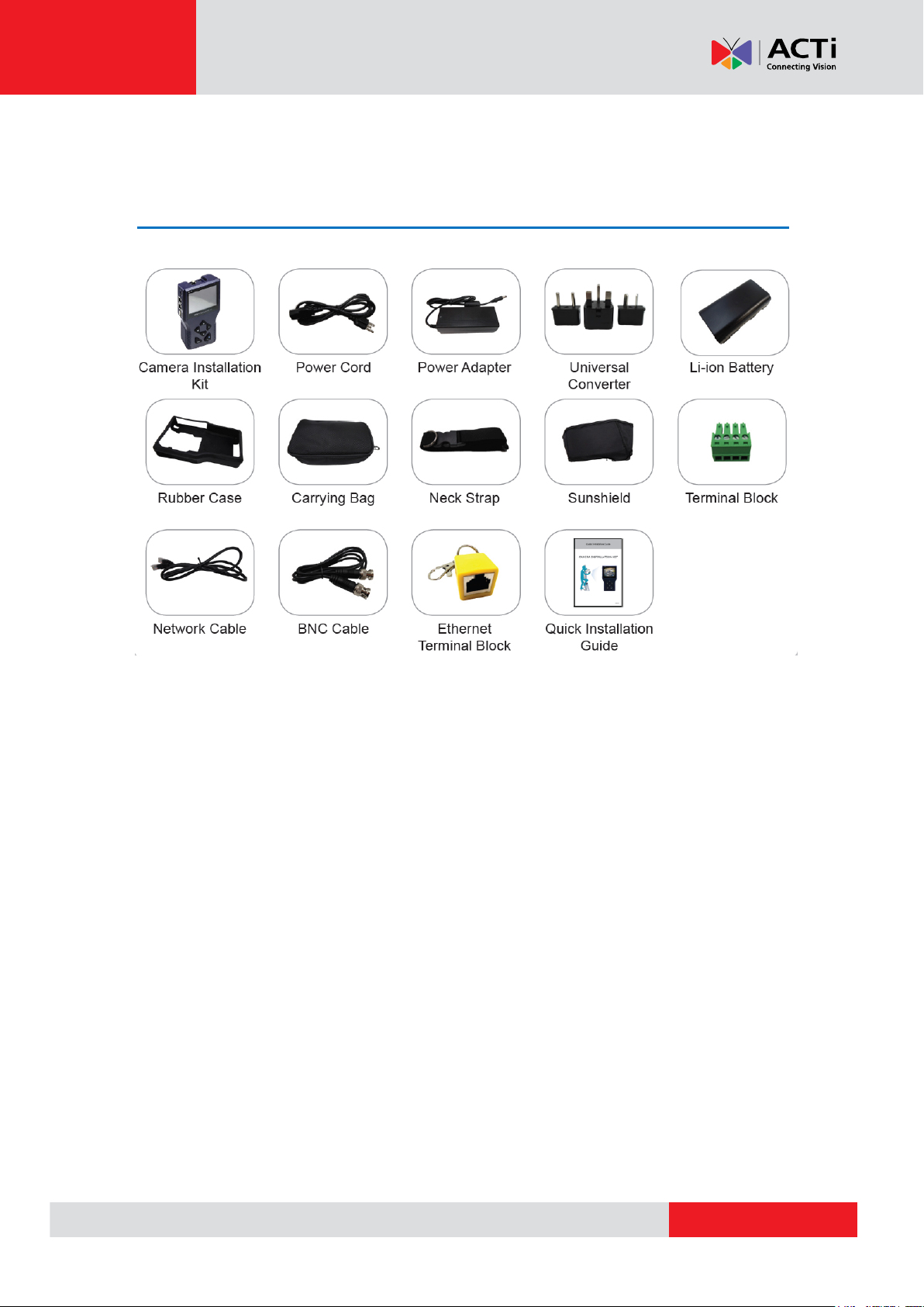
Package Contents
Product Manual
NOTE: The pictures are for reference only, actual items may slightly vary.
9
Page 10
www.acti.com
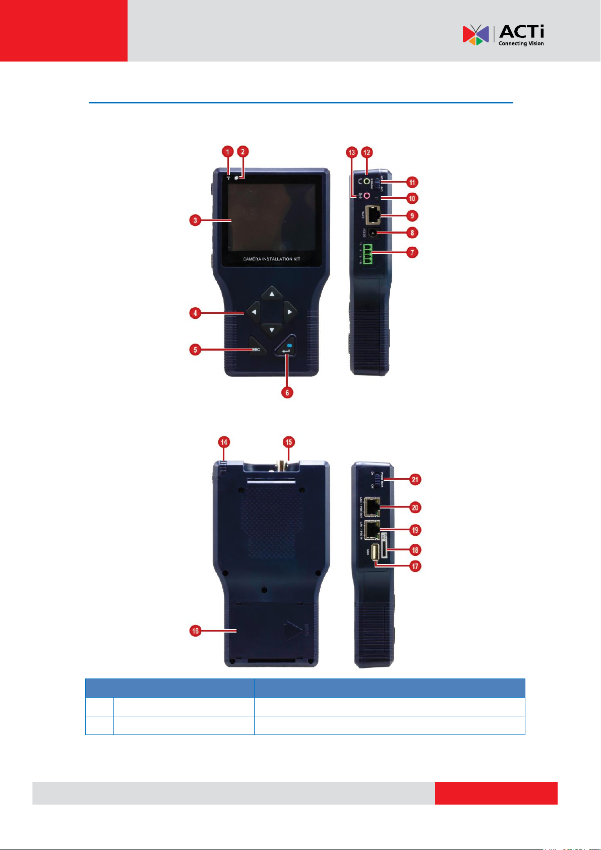
Physical Description
Item
Description
1
Power Indicator LED
Lights up when the device power is on.
2
Data Indicator LED
Flashes when the device is transmitting or receiving data.
Front and Right Views
Product Manual
Back and Left Views
10
Page 11

www.acti.com
Product Manual
Item
Description
3
LCD Screen
Displays the video and on-screen display (OSD) menu
options.
4
Navigation Keys
Press the corresponding arrow to move through the menu
items on screen or perform PTZ functions when viewing a
PTZ camera.
5
ESC Key
Press to exit the current page without saving or return to
the previous page.
6
Power / Snapshot / Enter
Key
Power Function
Press and hold this key for at least 3 seconds to turn on
the device. Make sure the main power switch is switched
on.
Snapshot Function
When viewing a video, press this key to capture the snap
shot of the current video.
Enter Key Function
While navigating a menu, press this key to enter a
submenu or select an option.
7
Serial Port Connector
Connects to a serial device, such as a PTZ scanner, etc.,
using RS-485 protocol.
8
DC 12V Power Connector
Connects to the bundled power adapter to charge the
device battery.
9 Ethernet Cable Tester Port
Use for Ethernet cable testing. Connect one end of the
network cable to this port and the other end to the bundled
Ethernet Terminal Block to detect wiring types
(Straight/Cross) or errors (Open, Short, Miswired) from the
displayed wire map on the LCD screen.
10
Battery Charging Indicator
LED
Lights up while the battery is charging.
11
Power Switch
Slide the switch to turn the main power on or off.
12
Audio Output Jack
Connects to an audio output device, such as a headset,
etc.
13
Audio Input Jack
Connects to an audio input device, such as a microphone.
14
Stylus
Use to tap on the LCD screen.
15
BNC Connector
Connects to an analog input device, such as a camera or
encoder using BNC connection.
16
Battery Compartment
Houses the device battery.
11
Page 12

www.acti.com
Product Manual
Item
Description
17
USB Port
Connects to a USB device for data storage or to update
the device firmware.
18
Memory Card Slot
Insert a memory card into this slot for data storage.
19
LAN Port / PSE Input
Connects to a Power Supply Equipment (PSE) input,
which can be used to provide DC 48V power to the IP
camera connected to the PoE Output port. To enable this
function, the Power Bank Switch must be “ON”.
20
LAN Port / PoE Output
Connects to an IP Camera. This port provides
Power-over-Ethernet (PoE) output that can power up the
camera.
21
Power Bank Switch
Slide the switch to turn the power bank function on or off.
When switched on, the PSE input connected to the PSE
IN port will supply power to the camera which is connected
to the PoE OUT port.
12
Page 13
www.acti.com
Product Manual
Preparing the Device
Charging the Battery
Charge the bundled Li-ion battery approximately for two (2) hours before use. The battery
supports up to three (3) hours of operating time and varies depending on the connected camera.
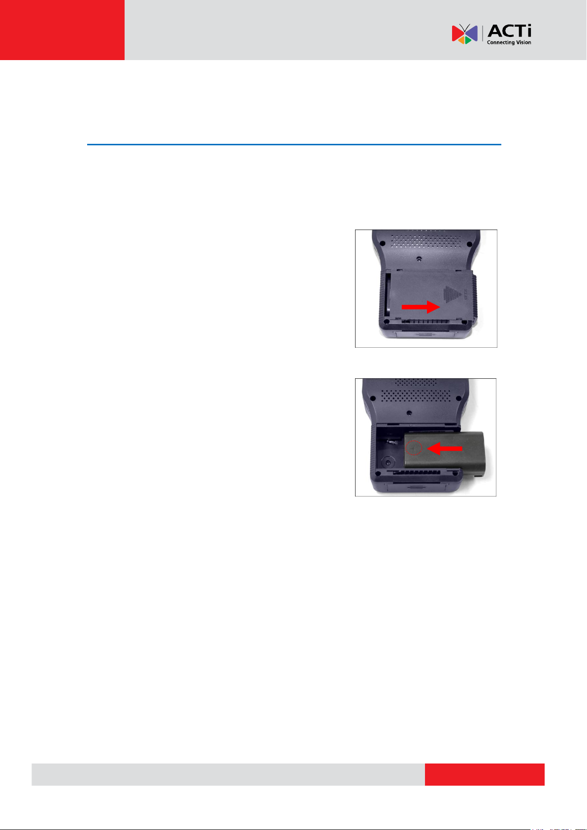
To charge the battery, do the following:
1. Slightly press and slide to open the battery
compartment cover.
2. Insert the battery towards the direction indicated
by the battery arrow.
3. Close the battery compartment cover.
4. Connect the adapter to the DC 12V Power Connector of the device.
5. Connect the power cord to the power adapter.
6. Plug the power cord to a power outlet.
The Charging Indicater LED lights up as the battery is being charged.
NOTE:
Use only the power adapter that is bundled with the device or approved by the
manufacturer.
When unplugging the power cord, pull on the plug head and not on the cable.
13
Page 14
www.acti.com
Product Manual
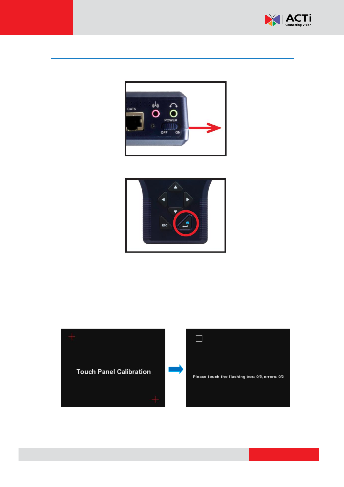
Powering On the Device
1. Slide the Power Switch to ON.
2. Press and hold the Power Key for at least 3 seconds. The Power Indicator LED lights up.
NOTE: The boot up process may take a while to complete.
Touch Panel Calibration
For first-time use, the Touch Calibration screen appears. Using the stylus, follow the on-screen
instructions to complete the calibration.
14
Page 15
www.acti.com
Product Manual
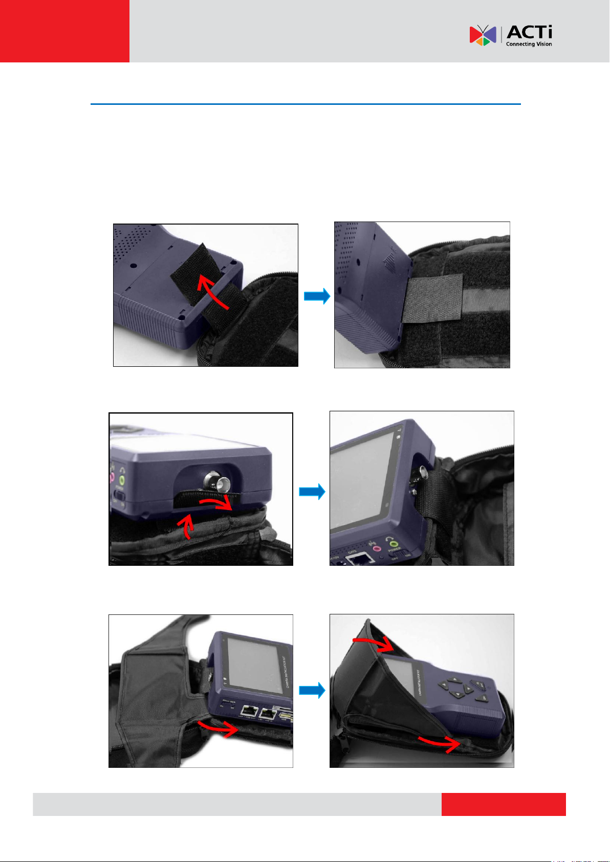
Using the Carrying Bag
For protection and convenience of use, you may use the rubber case for easy-grip or carrying
bag to protect and carry the device wherever you go.
To place the device in the carrying bag, do the following:
1. Insert the outer edge velcro through the bottom slot of the device.
2. Insert the inner edge velcro through the top slot of the device.
3. Attach the sunshield.
15
Page 16

www.acti.com
Product Manual
4. Close the bag and attach the neck strap.
16
Page 17
www.acti.com
Product Manual
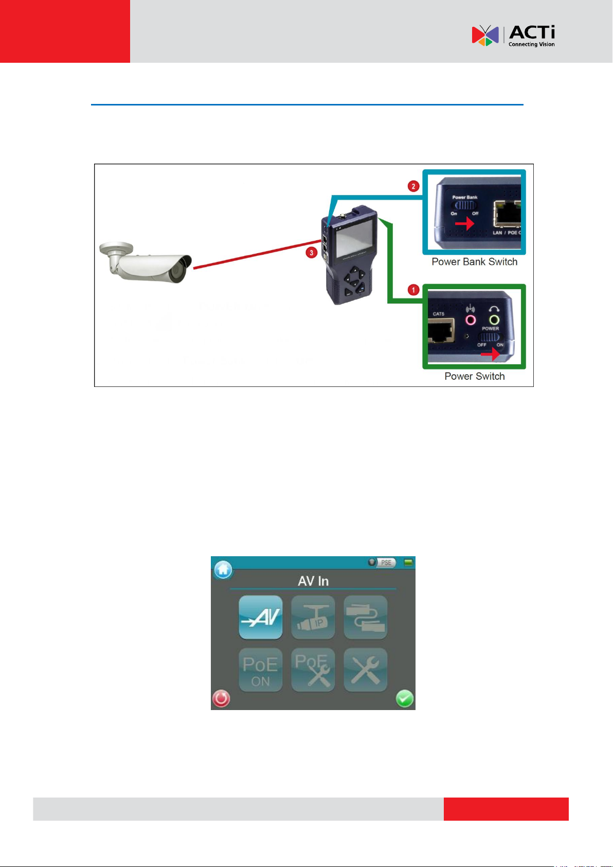
Connecting a Camera to the Device
After installing the IP camera, use the device to power up the camera via Power-over-Ethernet
(PoE).
1. Slide the Power Switch to “ON”.
2. Press and hold the Power Key for at least 3 seconds.
NOTE: The Power Indicator LED lights up. The boot up process may take a while to
complete.
3. Connect one end of the network cable to the camera and the other end to the LAN / POE
OUT port of the device. The Data Indicator LED flashes and the Main Menu appears after the
boot up process completes.
17
Page 18
www.acti.com
Product Manual
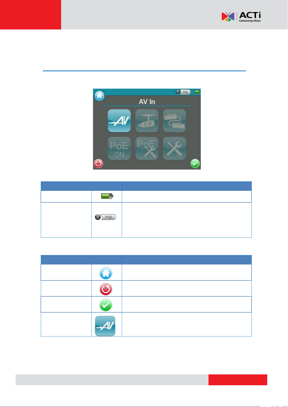
Item
Description
Battery Status
Indicates the battery level and charging status.
PSE
When the Tester is connected to an IP Camera that is PoE
enabled with the Tester’s PoE function on, the PSE button
will be lightened up, and the Camera will consume power
from the Device’s internal battery.
Item
Description
Main Menu
Return to the Main Menu.
Return
Click on this icon to go back to the previous page.
Enter/Save
Enter the submenu of a function or to save settings.
AV In
View the video display on the LCD screen via the video
output of the BNC supported Camera.
Screen Layout
Main Menu
The Main Menu of the Camera Installation Kit is shown as follows:
Status Icons
Buttons
18
Page 19

www.acti.com
Product Manual
Item
Description
IP Camera
Connect
Directly connect to the IP Camera with
one touch.
Device
Search
Ideal for testing multiple IP Cameras. Tap
this icon to find all the IP Cameras in the
network. Then select a specific IP Camera
by IP or MAC from the address list.Users
have to access “Setup> Setup- IP>
Setup- IP connection” for choosing
Camera Type. And relative IP Cameras
will be filtered out.
UPnP
Tap this icon to find all the IP Cameras
with UPnP names in the network. Then
select a specific IP Camera from the
address list.
Users have to access “Setup> Setup- IP>
Setup- IP connection” for choosing
Camera Type. And relative IP Cameras
will be filtered out.
Cable Test
Detects the CAT5 Cable for wiring types (Straight/Cross)
or errors (Short / Open / Miswired).
Power Over
Ethernet
Tap this icon to enable Power over Ethernet (PoE) output
for IP Cameras that are PoE / PoE Plus enabled. And the
Camera will drain power from the Device’s internal battery.
PoE Setup
Select for PoE Setups including Power Level, Power over
Ethernet (PoE) measurement, PoE measurement display,
Enable PoE when booting, and PoE auto-shutdown time.
Setup
Various Setups for cameras and the Camera Installation
Kit can be configured here. Each setup is shown in the
following section: Setup Menu.
19
Page 20

www.acti.com
Product Manual
Item Description
Setup - AV
AV Video
Adjust analog video’s brightness, contrast and
sharpness.
AV Dome
Configure the Speed Dome Camera’s protocol,
baud rate and ID address.
Setup - IP
IP
connection
The Camera Installation Kit’s IP address and
the IP Camera’s basic profile including IP
address, camera type, user name, password
and streaming relevant information can all be
altered here.
IP camera
Configure the IP Camera’s network settings.
Additionally, it is allowed to load the relevant
settings from an IP Camera to the Device.
IP script
Adjust IP Camera video’s brightness, color
level, contrast and sharpness by editing the API
commands. Additionally, it is allowed to import
the relevant API commands from other IP
Camera to the Device.
Setup Menu
Press the <Setup> button in the Main Menu, and you will be automatically directed to the
Setup Menu as shown below.
20
Page 21

www.acti.com
Product Manual
Item Description
Setup - Snapshot
Preview and manage the snapshot files.
Setup - Video
Record
Setup
Setup the recording video file name, description,
and saving path.
Playback
Preview, playback and manage the video files.
Setup - System
The Camera Installation Kit’s system settings
include volume, LCD brightness, firmware
upgrade, factory default reset and auto shutdown
setup. The MAC address of the Device is also
displayed on this page for users’ reference.
21
Page 22

www.acti.com
Product Manual
AV In (Analog Video Live View)
Users can view analog video through the BNC IN connector on top of the Device as shown below.
Connect the BNC cable from the video output connector of the Camera to the BNC IN port on the
Device. Tap the <AV In> button on the Main Menu, and users can view live video on the
LCD screen.
To view live video from an IP Camera which supports BNC via AV In function, please make
sure the IP Camera streaming is set as “BNC Out”.
22
Page 23

www.acti.com
Product Manual
Speed Dome Camera Live View
Users can implement a Speed Dome Camera’s PTZ control in the live view mode.
NOTE: Make sure the Speed Dome Camera’s RS-485 lines are correctly connected to the
Device’s RS-485 terminal block, or PTZ control cannot be manipulated here. Please refer to the
PTZ control documentation for more RS-485 information.
Fixed Camera Live View
In the Fixed Camera’s live view mode, the TV System (NTSC / PAL) of the Camera will be
displayed on the left bottom of the screen as shown below.
Users may adjust video brightness, contrast or sharpness for different live viewing quality in
the <Setup- AV Video> function, which can be accessed by the following path: Setup>
Setup- AV> Setup- AV Video. For more detail, please refer to AV Video Setup on page 42.
23
Page 24

www.acti.com
Product Manual
Enable PTZ Control Function
Step 1: Tap the <Setup> button on the Main Menu and then tap <Setup- AV> to
enter it.
Step 2: Tap <Setup- AV Dome> and enter its setting page as shown below.
Step 3: Select <Enable> from the <Dome type> drop-down list.
Step 4: Tap <Enter/Save> to save the setting, and system will automatically direct to the
previous screen.
Step 5: Tap <Return> to return to the Setup Menu.
24
Page 25

www.acti.com
Product Manual
Implementing PTZ Control
Step 1: Tap <AV In> button in the Main Menu to enter the live view mode. Meanwhile,
there will be four arrow buttons displayed on the screen as shown below.
Step 2: Tap the arrows on the screen to pan and tilt the camera. And press the Up/Down Keys
( ) on the Device’s button pad for zooming in/out.
Users may adjust video brightness, contrast or sharpness for different live viewing quality in
the <Setup- AV Video> function, which can be accessed by the following path: Setup>
Setup- AV> Setup- AV Video. For more detail, please refer to AV Video Setup on page 42.
25
Page 26

www.acti.com
Product Manual
IP Camera Live View
The Camera Installation Kit can automatically detect and recognize the IP Camera that is
connected to it. Please connect the IP Camera to the Device’s LAN port; plug in the IP Camera if
not using PoE. For further information about PoE, please refer to Power over Ethernet (PoE) on
page 36.
Automatically Change Device IP Address
After the IP Camera is powered on, the Camera Installation Kit’s IP address will be automatically
detected and displayed on the screen.
Please refer to the following sections for connecting the IP Camera and viewing live video in
alternative ways.
Connect IP Camera (Direct Connection)
Setup for Direct Connecting
Tap the <IP Camera> icon on the Main Menu to enter the submenu.
26
Page 27

www.acti.com
Product Manual
Check the IP Camera Profile in the field under the <Connect> icon as shown below. The IP
Camera’s profile details including IP address, camera type, username, password, etc.
If there is any setting required to be altered, please go to <Setup- IP connection> to change
the related IP Camera settings. For more setup information, please refer to Setup- IP
Connection (Alter Camera Settings) on page 47.
Access the Camera
Tap the <Connect> icon on the IP Camera Submenu, and wait for searching to finish. Then
the live video will be displayed on the LCD screen.
Digital PT Control (For Fixed Camera)
In the IP Camera’s live view mode, the text “ZOOM” will be displayed on the right bottom of the
screen. Tap the text “ZOOM”, and the video will switch to the digital zoom mode (at maximum
digital zoom ratio). Meanwhile, the text “P & T” will be displayed on the left bottom of the screen
as shown below.
27
Page 28

www.acti.com
Product Manual
Press the Left/Right Keys ( ), and the image can be horizontally shifted to the left/right with
four steps respectively; Press the Up/Down Keys ( ), and the image can be shifted
upward/downward with four steps respectively. To leave the Digital PT Control mode, simply tap
“ZOOM.”
PTZ Control (For IP Speed Dome Camera)
In the IP Camera’s live view mode, the text “ZOOM” will be displayed on the right bottom of the
screen. Tap the text “ZOOM”, and the video will switch to the PTZ control mode. Meanwhile, there
will be four arrow buttons displayed on the screen as shown below. Tap the arrows on the screen
to pan and tilt the camera. And press the Up/Down Keys ( ) on the Device’s button pad
for zooming in/out.
Exit the Viewing Mode
Press the ESC Key on the Device’s button pad to exit the live view mode, and return to the
IP Camera Submenu.
28
Page 29

www.acti.com
Product Manual
Device Search
If there are multiple IP Cameras in the network, utilize <Device Search> to find all of the cameras.
<Device Search> can be accessed in IP Camera Submenu.
Implement Device Search
Tap <Device Search> icon, and wait for searching to finish. Then you will enter the Device
Search page as shown below.
Tap <IP/MAC> to switch the detected IP Camera displaying form between IP address and MAC.
Select the target IP Camera from the device finding list on the left top of the screen. And setup the
duration to wait until connecting to devises. For a custom setting, select <Custom> from the
drop-down and then enter the value in the field at the bottom of the setup page. Then tap
<CONNECT> beneath the Password column to start connecting. The live view video will be
displayed on the screen.
29
Page 30

www.acti.com
Product Manual
Digital PT Control (For Fixed Camera)
In the IP Camera’s live view mode, the text “ZOOM” will be displayed on the right bottom of the
screen. Tap the text “ZOOM”, and the video will switch to the digital zoom mode (at maximum
digital zoom ratio). Meanwhile, the text “P & T” will be displayed on the left bottom of the screen
as shown below.
Press the Left/Right Keys ( ), and the image can be horizontally shifted to the left/right with
four steps respectively; Press the Up/Down Keys ( ), and the image can be shifted
upward/downward with four steps respectively. To leave the Digital PT Control mode, simply tap
“ZOOM.”
PTZ Control (For IP Speed Dome Camera)
In the IP Camera’s live view mode, the text “ZOOM” will be displayed on the right bottom of the
screen. Tap the text “ZOOM”, and the video will switch to the PTZ control mode. Meanwhile, there
will be four arrow buttons displayed on the screen as shown below. Tap the arrows on the screen
to pan and tilt the camera. And press the Up/Down Keys ( ) on the Device’s button pad
for zooming in/out.
30
Page 31

www.acti.com
Product Manual
Exit the Viewing Mode
Press the ESC Key on the Device’s button pad to exit the live view mode, and return to the
IP Camera Submenu.
31
Page 32

www.acti.com
Product Manual
UPnP
Users can search all of the IP Cameras with UPnP names in the network via <UPnP> . To
access <UPnP> setup page, please tap <IP Camera> on the Main Menu and enter the IP
Camera Submenu.
Implement UPnP
Tap <UPnP> icon, and wait for searching to finish. Then you will enter the UPnP page as
shown below.
Select the target IP Camera from the device finding list on the left top of the screen. Then setup
the duration to wait until connecting to devises. For a custom setting, select <Custom> from the
drop-down and then enter the value in the field at the bottom of the setup page. After setup, tap
<CONNECT> beneath the Password column to start connecting. The live view video will be
displayed on the screen.
32
Page 33

www.acti.com
Product Manual
Digital PT Control (For Fixed Camera)
In the IP Camera’s live view mode, the text “ZOOM” will be displayed on the right bottom of the
screen. Tap the text “ZOOM”, and the video will switch to the digital zoom mode (at maximum
digital zoom ratio). Meanwhile, the text “P & T” will be displayed on the left bottom of the screen
as shown below.
Press the Left/Right Keys ( ), and the image can be horizontally shifted to the left/right with
four steps respectively; Press the Up/Down Keys ( ), and the image can be shifted
upward/downward with four steps respectively. To leave the Digital PT Control mode, simply tap
“ZOOM.”
PTZ Control (For IP Speed Dome Camera)
In the IP Camera’s live view mode, the text “ZOOM” will be displayed on the right bottom of the
screen. Tap the text “ZOOM”, and the video will switch to the PTZ control mode. Meanwhile, there
will be four arrow buttons displayed on the screen as shown below. Tap the arrows on the screen
to pan and tilt the camera. And press the Up/Down Keys ( ) on the Device’s button pad
for zooming in/out.
33
Page 34

www.acti.com
Product Manual
Exit the Viewing Mode
Press the ESC Key on the Device’s button pad to exit the live view mode, and return to the
IP Camera Submenu.
34
Page 35

www.acti.com
Product Manual
Cable Test (CAT5)
Users can check the RJ-45 cable wiring with the supplied UTP Terminal Block
Setup for Testing
Connect one end of the RJ-45 connector to the UTP Terminal Block and the other end to the
CAT5 port at the side of the Device.
Cable Testing
Step 1: Tap the <CAT5> icon on the Main Menu.
Step 2: Tap the <Test> icon and wait for wiring detection.
Step 3: Then the cable’s wire map will be displayed on the screen. Users can check the
RJ-45 cable for its wiring type (Straight/Crossover) and error connection (Shorts / Open /
Miswire).
Step 4: Tap <Return> to return to the Main Menu.
35
Page 36

www.acti.com
Product Manual
Power over Ethernet (PoE)
The Camera Installation Kit can function as the power sourcing equipment (PSE) and provide
power to IP Cameras that are PoE / PoE Plus enabled.
Enable PoE
Step 1: Connect the Ethernet cable from the IP Camera to the LAN / PoE OUT Port on the
side of the Device.
Step 2: Tap the <PoE ON> icon on the Main Menu to enable the PSE, then the PSE
indicator light will be on, which means the Device is now providing power to the IP
Camera.
Step 3: The <PoE ON> icon will turn into <PoE OFF> when the PoE is enabled. Users
may tap <PoE OFF> to turn off the PoE function.
36
Page 37

www.acti.com
Product Manual
PoE Setup
Tap the <PoE Setup> icon on the Main Menu to setup including Power Level, Power over
Ethernet (PoE) measurement, PoE measurement display, Enable PoE when booting, and PoE
auto-shutdown time, etc.
Power Level
The output Power Consumption Level range can be set according to different needs. The options
include <Very Low(~3W)>, <Low(3~5W)>, and <Mid-High(6~25W+EXT 12V)>.
NOTE: Please make sure the PoE function is off before Power Level setting.
37
Page 38

www.acti.com
Product Manual
PoE Measurement
The information includes voltage (V), current (I) and power consumption (P) of the Power over
Ethernet (PoE) can be measured according to different Ethernet circumstances. Select from the
drop-down list of the <PoE Measurement> to fit your Ethernet condition to show the PoE
Measurement information on the screen while using PoE.
PoE Measurement Display
There are several combinations in <PoE Measurement Display>, select from the drop-down list to
show PoE Measurement information including Voltage (V), Current (I), and Power Consumption
(P) in different combination.
38
Page 39

www.acti.com
Product Manual
Enable PoE after Device Bootup
For users who wish to enable PoE in the meantime while the Device is booting up, please select
<ON> from the drop-down list of <Enable PoE when booting>, and the Device will provide
electricity to the IP Camera right after system startup.
PoE Auto-shutdown
Select the PoE auto-shutdown interval between 20 seconds, 40 seconds and 60 seconds. The
setup can aid conserving battery power when there is no IP Camera or other device using the
Device as the PSE. The reminder of PoE shutdown will pop out around 5 seconds in advance of
shutting down.
Tap <Enter/Save> to save all the settings and you will then automatically directed to the
Main Menu. Or tap <Return> to exit the setting page without saving settings.
39
Page 40

www.acti.com
Product Manual
Snapshot
The advanced Snapshot function facilitates saving images in the assigned path when necessary.
Take Snapshot
In the IP Camera’s live view mode, press the <Snapshot> key on the Device’s button pad.
Then enter the Snapshot setup page as shown below.
Snapshot File Setup
Assign a storage location among the three options (Device / USB / SD) located on the very top of
the snapshot setup page for the snapshot by tapping the round button on the left side of the
option. And then enter the file name and description respectively for the snapshot.
Tap <Enter/Save> to save all the settings and return to the live view mode, or tap <Return>
to exit the setting page without saving settings.
Files in USB / SD
For files that are saved to the USB drive or Micro SD card will automatically be in the created
folder named “IMAGE-DATA”. Each snapshot’s description can be found in the attached .txt file.
40
Page 41

www.acti.com
Product Manual
Video Recording
The Device supports Video Recording, Video Setup, Video File Managing and Video Playback
function for IP Camera live views when necessary.
Record Video
In the IP Camera’s live view mode, tap the white text “REC” on the right top corner of the live view
screen to start Video Recording. During the recording process, the text will be in red. Tap the text
“REC” one more time to stop Video Recording, and the text will be back in white again.
41
Page 42

www.acti.com
Product Manual
AV Video Setup
The <Setup- AV Video> can be accessed by the following path: Setup> Setup- AV> Setup- AV
Video. In the <Setup- AV Video> menu, users can adjust analog video’s brightness, contrast
or sharpness for favorable video display on the Device’s LCD screen under different operating
circumstances.
Access <Step- AV Video>
Step 1: Tap <Setup> on the Main Menu and enter the Second Screen.
Step 2: Tap <Setup- AV> on the Setup Menu to enter the AV Setup Screen, and then
tap <Setup- AV Video> to enter the setting page as shown below.
In the <Setup- AV Video> setting page, the live video is displayed on the upper screen.
42
Page 43

www.acti.com
Product Manual
Adjust Brightness / Sharpness / Contrast Value
Move the slider bar by touching the screen or using the Device’s Left/Right Keys ( ).
Switch to another Item
Tap the <AV Mode> icon next to the slider bar or press the Device’s Up/Down Keys to
switch among Brightness, Sharpness and Contrast setting.
Tap <Enter/Save> to save all the settings and you will then automatically directed to the
previous page. Or tap <Return> to exit the setting page without saving settings.
AV Dome Setup
In the <Setup- AV Dome> menu, users can enable / disable PTZ control and configure the
Speed Dome Camera’s protocol, baud rate and ID address.
Access <Step- AV Dome>
Step 1: Tap <Setup> on the Main Menu and enter the Second Screen.
Step 2: Tap <Setup- AV> on the Setup Menu to enter the AV Setup Screen, and then
tap <Setup- AV Dome> to enter the setting page as shown below.
43
Page 44

www.acti.com
Product Manual
Set the Dome Type
Select <Enable> or <Disable> from the drop-down list of the <Dome Type>. <Enable> means
activating PTZ control on the Camera Installation Kit, while <Disable> indicates disabling PTZ
control on the Device.
Set the Protocol
Select the protocol for the Speed Dome Camera from the drop-down list.
Set the Baud Rate
Select the baud rate for the Speed Dome Camera from the drop-down list.
Set the ID Address
Enter the three-digit ID address.
Tap <Enter/Save> to save all the settings and you will then automatically directed to the
previous page. Or tap <Return> to exit the setting page without saving settings.
44
Page 45

www.acti.com
Product Manual
IP Camera Setup
Users can change the IP Camera’s setting, e.g. IP address, camera type, user name, password,
streaming format, network settings, in the Setup- IP Submenus: <Setup- IP Connection>
and <Setup- IP Camera> .
Access <Setup-IP Connection> and <Setup-IP camera>
Step 1: Tap the <Setup> icon on the Main Menu to enter the Second Screen.
Step 2: Tap <Setup- IP> on the Setup Menu, and then enter the IP Setup Submenu.
45
Page 46

www.acti.com
Product Manual
The <Setup- IP Connection> icon and <Setup- IP Camera> icon are in the IP Setup
Submenu.
46
Page 47

www.acti.com
Product Manual
Setup- IP Connection (Alter Camera Settings)
Tap the <Setup- IP Connection> icon and enter its setup page as shown below.
Specify Camera Settings
Please specify the IP address, camera type, user name, password, HTTP Port, streaming
settings (Streaming port / Format / Protocol), etc. of the connected IP Camera in each column by
the stylus touch pen.
47
Page 48

www.acti.com
Product Manual
Add a Camera to List
To add a camera to the Camera Profile list, please enter its model name in the <Camera Profile>
column and tap the icon on the right side of this column; while canceling a camera, select
the camera to be deleted, and then tap the icon . Up to 128 IP Cameras can be assigned for
testing.
Tap <Enter/Save> to save all the settings and you will then automatically directed to the
previous screen. Or tap <Return> to exit the setting page without saving settings.
Setup- IP Camera (Load the Network Settings)
For checking or altering the IP Camera’s network settings such as Subnet mask, Default gateway,
Primary DNS, Web server port, etc., users can go to the <Setup- IP Camera> page. Tap the
<Setup- IP Camera> icon and enter its setup page as shown below.
Load Settings from the IP Camera
Please tap the <Load from Camera> button on the top of the menu and the IP Camera’s network
settings will be shown in the blank field.
NOTE: Make sure the target camera’s settings are correctly configured, or the loading here
will fail. For altering the camera settings, please go back up one level by tapping on <Return>
button. Then enter <Setup- IP Connection> to change camera settings.
Reload the Settings to the IP Camera
After making network setting changes, users may tap the <Set to Camera> button on the top of
the setup page to reload the network settings to the camera.
48
Page 49

www.acti.com
Product Manual
Tap <Enter/Save> to save all the settings and you will then automatically directed to the
previous screen. Or tap <Return> to exit the setting page without saving settings.
Setup- IP Script (IP Camera API Commands)
Tap the <Setup- IP Script> icon and enter its setup page as shown below.
This script tool can be used to set any of the API commands supported by the IP Camera. The
unit is supplied with a default set of commands already loaded, but these can be replaced or
added to as required. It is also possible to create / edit a script on a PC and then tap the <Import>
button to load it via a USB stick (name the file script.txt).
Tap <Save> button to save the settings, or tap <Enter/Save> to save and return to the
previous screen. Tap <Return> to exit the setting page without saving settings.
49
Page 50

www.acti.com
Product Manual
Snapshot Setup
Users can preview, copy and delete the image on the <Setup- Snapshot> setup page. Tap the
<Setup> icon on the Main Menu and tap on <Setup- Snapshot> icon to enter the
snapshot file managing page as shown below.
Image Preview
On the <Setup- Snapshot> page, select the snapshot storage path (Device / USB / SD) where
the saved files are located. Then all the files will be listed in the <File List> field. To view a
snapshot, tap the file name in the list and the image will appear in <Image Preview> as shown
above.
Single File Copy
Tap the file name in the list to Copy, and then tap the <Copy> icon in <File Manager>
section below <Image Preview>. Select the location to copy the file to in the pop out window, and
then tap <Enter/Save> .
50
Page 51

www.acti.com
Product Manual
All Files Copy
Tap the <Select All> con in <File Manager> section below <Image Preview> to select all the
files in <File List>. Then tap the <Copy> icon to copy all the files. Select the location to copy
the files to in the pop out window, and then tap <Enter/Save> .
Single File Deletion
Tap the file name in the list to delete then tap the <Delete> icon in <File Manager> section
below <Image Preview>. Tap <OK> on the pop out window to allow file deletion.
All Files Deletion
Tap the <Select All> icon in <File Manager> section below <Image Preview> to select all
the files in <File List>. Then tap the <Delete> icon to delete all the files. Tap <OK> on the
pop out window to allow all files deletion.
51
Page 52

www.acti.com
Product Manual
Video Setup
Follow the steps below to setup for video recording.
Video Recording Setup (Video- Rec Setup)
Step 1: Tap the <Setup> icon on the Main Menu to enter the Second Screen. Enter
<Setup- Video> by tapping the icon.
Step 2: Tap <Video- Rec setup> icon on the Video Setup Screen to access video
recording setup page.
52
Page 53

www.acti.com
Product Manual
Assign a storage location among the three options (Device / USB / SD) located on the very top of
the setup page to save the videos by tapping the round button on left side of the option. And then
enter the file name and description respectively for the snapshot.
Tap <Enter/Save> to save all the settings and return to the live view mode, or tap <Return>
to exit the setting page without saving settings.
53
Page 54

www.acti.com
Product Manual
Video Playback
Users can preview, copy and delete the video on the <Video- Playback> page. Tap the <Setup>
icon on the Main Menu and tap on <Setup- Video> to enter the Video Setup Screen.
Then tap on <Video- Playback> icon to access video play back page.
On the <Setup- Snapshot> page, select the recording video storage path (Device / USB / SD).
Then all the video files will be listed in the <File List> field. To view a video, tap the file name in
the list and tap the <Playback> button on the bottom, the video will appear as full screen.
In the Video Playback mode, press the <ESC> key on the Device’s button pad to stop
playback and return to video playback page.
54
Page 55

www.acti.com
Product Manual
Single File Copy
Tap the file name in the list to Copy, and then tap the < Copy> icon in <File Manager>
section below <Image Preview>. Select the location to copy the file to in the pop out window, and
then tap <Enter/Save> .
All Files Copy
Tap the <Select All> icon in <File Manager> section below <Image Preview> to select all
the files in <File List>. Then tap the <Copy> icon to copy all the files. Select the location to
copy the files to in the pop out window, and then tap <Enter/Save> .
Single File Deletion
Tap the file name in the list to delete then tap the <Delete> icon in <File Manager> section
below <Image Preview>. Tap <OK> on the pop out window to allow file deletion.
All Files Deletion
Tap the <Select All> icon in <File Manager> section below <Image Preview> to select all
the files in <File List>. Then tap the <Delete> icon to delete all the files. Tap <OK> on the
pop out window to allow all files deletion.
55
Page 56

www.acti.com
Product Manual
System Setup
On the system setup page, users can adjust the volume or the brightness of the Camera
Installation Kit’s LCD screen, implement firmware upgrade, restore all the system settings to
factory default and auto shutdown time.
Access <Setup- System>
Step 1: Tap the <Setup> icon on the Main Menu.
Step 2: Tap the <Setup- System> icon on the Setup Menu to enter the Device’s
system setup page.
56
Page 57

www.acti.com
Product Manual
Adjust Device Volume
Move the slider bar of <Volume>. Greater volume represents louder sound.
Adjust Device Screen Brightness (Backlight)
Move the slider bar of <Backlight>. Greater value represents higher brightness.
Tap the <Auto Control> tick box below the <Backlight> slider bar to lock the level on the slider bar.
Tap the <Auto Control> tick box again to cancel the selection; then the slider bar above will
become movable again.
Upgrade Firmware
Before implementing firmware upgrade, please make sure the firmware is located in the path:
“upgrade\upd_dt02s\” in your USB drive.
Step 1: Tap the <Upgrade> button, and the file selection dialogue will come out.
57
Page 58

www.acti.com
Product Manual
Step 2: Press the <USB> button, and the firmware in the USB drive shall be found. The
firmware details will be displayed in the blank field of the file selection menu.
Step 3: Check the <Complete upgrade> tick box by tapping, and tap <Enter/Save>
button to start upgrade. Then the notice of firmware upgrade confirmation will pop up. Tap
<OK> and the firmware upgrade will proceed.
Reset to Factory Defaults
Users can restore the Device system to factory defaults by implementing this function.
Step 1: Tap the <Default> button. Then the notice of resetting to factory default will pop up.
Tap <OK> to continue.
Step 2: The pop-up message of stating successful reset with request for system reboot
will display on the screen. Tap <OK> and the Device will be shut down.
Step 3: Reboot the Camera Installation Kit after system reset. You will be first directed to the
Touch Panel Calibration mode as shown below.
Step 4: Tap the flashing cross on the left top of the screen. And then hit the other flashing
cross located diagonally.
58
Page 59

www.acti.com
Product Manual
Step 5: Then touch each flashing box coming out as instructed.
The screen mode will switch to Main Menu after Touch Panel Calibration is completed.
Auto Shutdown
The system can be automatically shutdown after pre-determined time range when idle. Select the
specific time interval from the drop-down list for system auto shutdown. To disable the <Auto
Shutdown> function, please select <OFF>.
59
Page 60

Copyright © 2015, ACTi Corporation All Rights Reserved
7F, No. 1, Alley 20, Lane 407, Sec. 2, Ti-Ding Blvd., Neihu District, Taipei, Taiwan 114, R.O.C.
TEL : +886-2-2656-2588 FAX : +886-2-2656-2599
Email: sales@acti.com
 Loading...