

Page 1

CMS-200
System Administrator’s Manual
2016/04/01
For V2.0.09 version
Page 2

www.acti.com
CMS-200 System Administrator’s Manual
About This Manual
Target Audience
This manual is intended for System Administrators who are responsible for installing and
setting up CMS surveillance system. The reader is expected to know the fundamentals of IP
surveillance system integration and to own the administrative privileges to achieve all the
configuration tasks.
Content Overview
This manual provides information needed for planning the installation, installing, setting up the
system and configuring the video streaming devices. Its main content consists of the following
three sections:
Getting Started provides the preparatory knowledge you should study before starting
installation, such as system requirements and license registration procedures.
Log in to the System explains how to log in to the system right after a successful
installation.
System Setup gives instructions on administrative tasks such as centrally managing the
NVR servers and the devices, setting up event rules, customize the live view layouts or
managing system storage. For each major task, you will be given a brief introduction of
operation principles, step-by-step instructions, and a simple tip to check if you have done
it correctly.
2
Page 3

www.acti.com
CMS-200 System Administrator’s Manual
Important Notice
Tip
The content within this box is a tip. A tip gives you an alternative method to easily or quickly
achieve an objective, usually for specific conditions.
The content within this box is an important notice. This notice is important for you to get
certain functions to work properly, or to prevent from certain potential problems that may
damage your system. Make sure you read this notice and follow the instructions.
Note
The content within this box is a note. A note is some necessary information you need to know
about the action you are currently taking, like what will happen after you follow or do not follow
certain procedure.
Technical Support
If you have any questions during system installation, please feel free to contact our engineers
via our Customer Help Desk platform http://www.acti.com/CHD.
Conventions Used in This Manual
The following are typographic conventions used in this manual:
Bold: Bold typeface is used for a keyword, major functions of CMS, or a title of a
section/column.
Italic: Italic typeface is used for a filename or location path.
Underlined: Underlined typeface is used for a document name or hyperlink.
“Bold”: Bold interface enclosed in double quotation marks indicates the name of a button, a
menu or a choice item.
Some notices are placed within the following boxes; each type of the box indicates different
purposes or levels of importance for system:
3
Page 4

www.acti.com
CMS-200 System Administrator’s Manual
Legal Notice
Disclaimer
The information contained in this document is intended for general information purposes.
ACTi Corporation shall not be liable for errors contained herein or for incidental or
consequential damages arising from the furnishing, performance, or use of this manual.
The information contained herein is subject to change without notice.
The English version of this document is the official one for all purpose. All the translated
versions are provided as a convenience. Any discrepancies or differences created in the
translations of any other languages are not legally binding.
Copyright
Copyright ©2016 ACTi Corporation All Rights Reserved.
Trademarks
ACTi Connecting Vision and its logo are registered trademarks of ACTi
Corporation.
Internet Explorer®, Microsoft®, and Windows® are registered trademarks of Microsoft
Corporation in the United States and in other countries. All other product or company names
mentioned in this document may be trademarks or registered trademarks of their respective
owners.
4
Page 5

www.acti.com
CMS-200 System Administrator’s Manual
Regulatory Compliance Information
Federal Communications Commission Statement
This equipment has been tested and found to comply with the limits for a
Class B digital device, pursuant to Part 15 of the FCC Rules. These
limits are designed to provide reasonable protection against harmful
interference in a residential installation. This equipment generates, uses
and can radiate radio frequency energy and, if not installed and used in accordance with the
instructions, may cause harmful interference to radio communications. However, there is no
guarantee that interference will not occur in a particular installation. If this equipment does
cause harmful interference to radio or television reception, which can be determined by turning
the equipment off and on, the user is encouraged to try to correct the interference by one or
more of the following measures:
- Reorient or relocate the receiving antenna.
- Increase the separation between the equipment and receiver.
- Connect the equipment into an outlet on a circuit different from that to which the receiver is
connected.
- Consult the dealer or an experienced radio/TV technician for help.
WARNING: Changes or modifications to the equipment that are not expressly approved by the
responsible party for compliance could void the user’s authority to operate the equipment.
European Community Compliance Statement
This product has been tested and found to comply with the limits for
Class B Information Technology Equipment according to European
Standard EN 55022 and EN 55024. In a domestic environment, this
product may cause radio interference in which cause the user be require
to take adequate measures.
5
Page 6

www.acti.com
CMS-200 System Administrator’s Manual
Table of Contents
1 About This Manual 2
Target Audience ....................................................................................... 2
Content Overview .................................................................................... 2
Technical Support .................................................................................... 3
Conventions Used in This Manual .......................................................... 3
2 Legal Notice 4
Disclaimer ................................................................................................ 4
Copyright ................................................................................................ 4
Trademarks ................................ ................................ ............................... 4
Regulatory Compliance Information ...................................................... 5
3 Table of Contents 6
4 Overview 8
CMS Server / Client Architecture ............................................................ 9
Client PC System Requirements .......................................................... 11
5 Getting Started 13
What’s in the Box ................................................................................... 13
At a Glance ............................................................................................. 14
Connect the Devices .............................................................................. 15
Start and Turn Off the Unit .................................................................... 16
Enter Windows ....................................................................................... 16
Configure the IP Address ...................................................................... 17
6 Log In to the System 20
License and Activation .......................................................................... 20
Access CMS Server via Internet Explorer ............................................ 24
Access CMS Server via Workstation .................................................... 26
6
Page 7

www.acti.com
CMS-200 System Administrator’s Manual
7 Set up the System 29
CMS Main Screen ................................................................................... 29
Manage Users......................................................................................... 30
Manage NVRs ......................................................................................... 37
Event Management ................................................................................ 44
System Log ............................................................................................ 52
Customize Views .................................................................................... 56
Customize System Language ............................................................... 68
Display Configurations .......................................................................... 71
Video & Snapshot Export Configurations ............................................ 72
Joystick .............................................................................................. 73
Un-install Server Software .................................................................... 74
8 Back up System Data 76
9 Restore System Data 78
Advanced Administrative Tasks ........................................................... 79
7
Page 8
www.acti.com
CMS-200 System Administrator’s Manual
Microsoft ® Windows Embedded
Standard 7 Professional
CMS2
Server
CMS2
Workstation
Overview
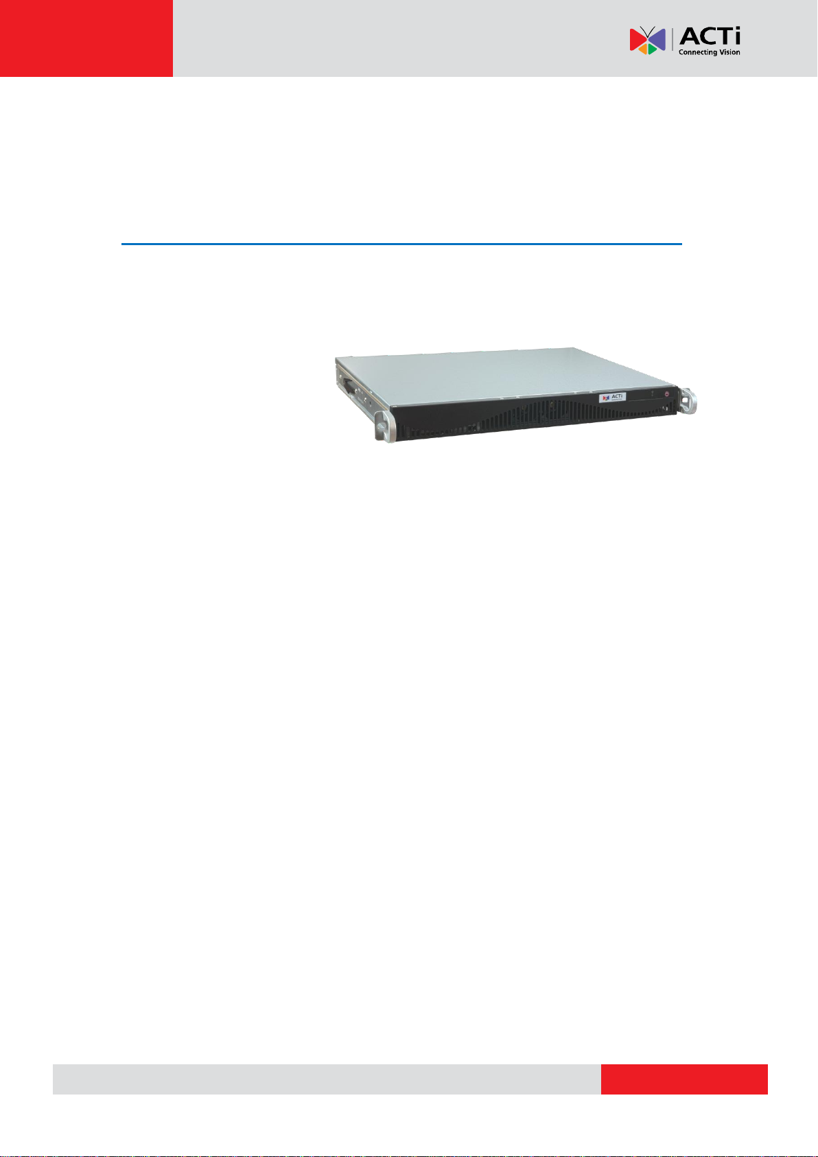
CMS-200 (hereafter referred to as CMS) is a compact and reliable multi-channel standalone
CMS. It contains a pre-installed Windows operating system, and ACTi CMS central video
management software along with client software.
This unit is composed of:
Computer
A PC, with Microsoft ® Windows Embedded Standard 7 Professional operating system
pre-installed.
CMS 2 Server
Designed for large-scale multi-site video surveillance solution, Central Management System
2.0 software allows its user the full capabilities to monitor and manage multiple Network
Video Recorders (NVR) via network. It also possesses full functionalities to manage not only
NVRs but also devices (network cameras, video encoders, etc.), users and events.
CMS 2 Client Application
The dedicated client application of CMS system – CMS2 Workstation, allowing the user to
directly access CMS interface. A remote client can also access this system via network.
8
Page 9

www.acti.com
CMS-200 System Administrator’s Manual
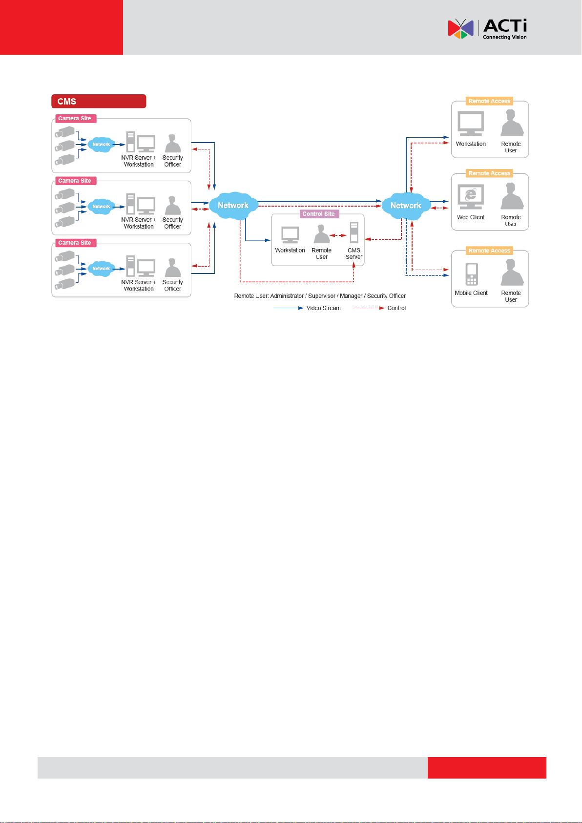
CMS Server / Client Architecture
CMS is a typical web-based server/client system. In a multi-site surveillance solution, CMS
Server serves as a management command center; a Client makes requests of monitoring
video streams or playing recordings sent to CMS Server, and CMS Server will pass this
request to the involved NVR Server to send data/video stream to the Client. CMS Server
starts automatically as soon as the Server computer (where it is installed) boots up, and
operates in the background without requiring the login of administrator. It would provide
services over the TCP/IP network to multiple Clients upon requests coming through HTTP
protocol.
There are two types of Clients in CMS system: Web Client and Workstation Client. A user,
connecting from whether web browser or workstation, will be provided with the same user
interface and be CMS functions.
Web Client: the web version of interface to access CMS Server without the need of
installing any client program. Logging in to the CMS Server is as simple as visiting a website
through the browser.
Workstation Client: the client application making accessing CMS Server free from the use
of browser .The workstation includes a set of programs that provide interface between users
and the CMS Server.
9
Page 10
www.acti.com
CMS-200 System Administrator’s Manual
10
Page 11

www.acti.com
CMS-200 System Administrator’s Manual
Minimum
PC Spec
Display
Mode
Live Layout
(*2)
Number of Channels
1-16,00
1,601-unlimited
Remote
Client PC
11-16
Intel Core 2 Quad 2.4 GHz
Intel Core i5 2.4 GHz
17-64
Intel Core i5 2.4 GHz
Intel Core i7-920 2.67 GHz
RAM
4GB
(*3)
Operating
System
Windows 7, Windows 8, Windows Server 2008(*4), Windows Server 2012
Browser
Internet Explorer 10 and 11
Network
Ethernet (1000 Base-T recommended)
Display
Resolution: 1024 X 768 or higher
Recommended
PC Spec
O/S: Windows 7 (latest service packs), Browser: Internet Explorer 9 (Web client),
CPU: Intel Core i7-920 2.67 GHz, RAM: 4GB, Display Resolution: 1080p
Network Adapter: Ethernet 1000 Base-T
Client PC System Requirements
The minimum CPU Processor spec will provide acceptable performance for systems that
use mostly MPEG4 streams.
For a system that has more than 1600 channels or more than 16 live view channels should
satisfy Recommended PC Spec for good performance.
*1 These specifications are based on following camera settings:
Single stream mode 1280x1024, 3Mbps, 18fps, MPEG-4
Dual stream mode1280x1024, 3Mbps, 18fps, H.264 (recording);
640x480, Quality: 100, 18fps, MJPEG (live view).
*2 Live view of multiple channels requires good hardware for smooth performance. If your
live view performance is not satisfactory, please reduce the number of channels viewed at
the same time, and use Layout Patrol to scan through all the channels or views instead.
*3 Please use 64-bit system if your computer has more than 4GB RAM. Microsoft Windows
operating system has limits on memory and address space, regardless of the real or virtual
memory available on a particular computer. Take Windows 7 Professional for example, the
maximum physical memory for a 32-bit(X86) system can address is 3.5 GB even though 16
GB of RAM has been installed on this computer. Therefore, if you consider increasing the
computer’s multi-tasking capability by adding more RAM, you will need a 64-bit version of
Windows to take advantage of it all.
Please visit the link below for more memory limitations on various Windows platforms.
11
Page 12

www.acti.com
CMS-200 System Administrator’s Manual
http://msdn.microsoft.com/en-us/library/aa366778%28VS.85%29.aspx#physical_memory_li
mits_windows_7
Besides the limitation mentioned above, you may find the usable memory displayed on
Computer Properties is still less than actual installed memory.
This is a common symptoms of all Windows platforms, please find explanations and
solutions in this Windows official support document
http://support.microsoft.com/kb/978610/en-us and
http://windows.microsoft.com/en-us/windows7/taking-the-mystery-out-of-64-bit-windows
*4 Please make sure your operating system is fully patched with the latest service packs.
12
Page 13
www.acti.com
CMS-200 System Administrator’s Manual
Getting Started
What’s in the Box
This product package includes the following items:
CMS-200 x 1
Power Cord x 1
Universal Converter x 1
Warranty Card x 1
Quick Installation Guide x 1
13
Page 14
www.acti.com
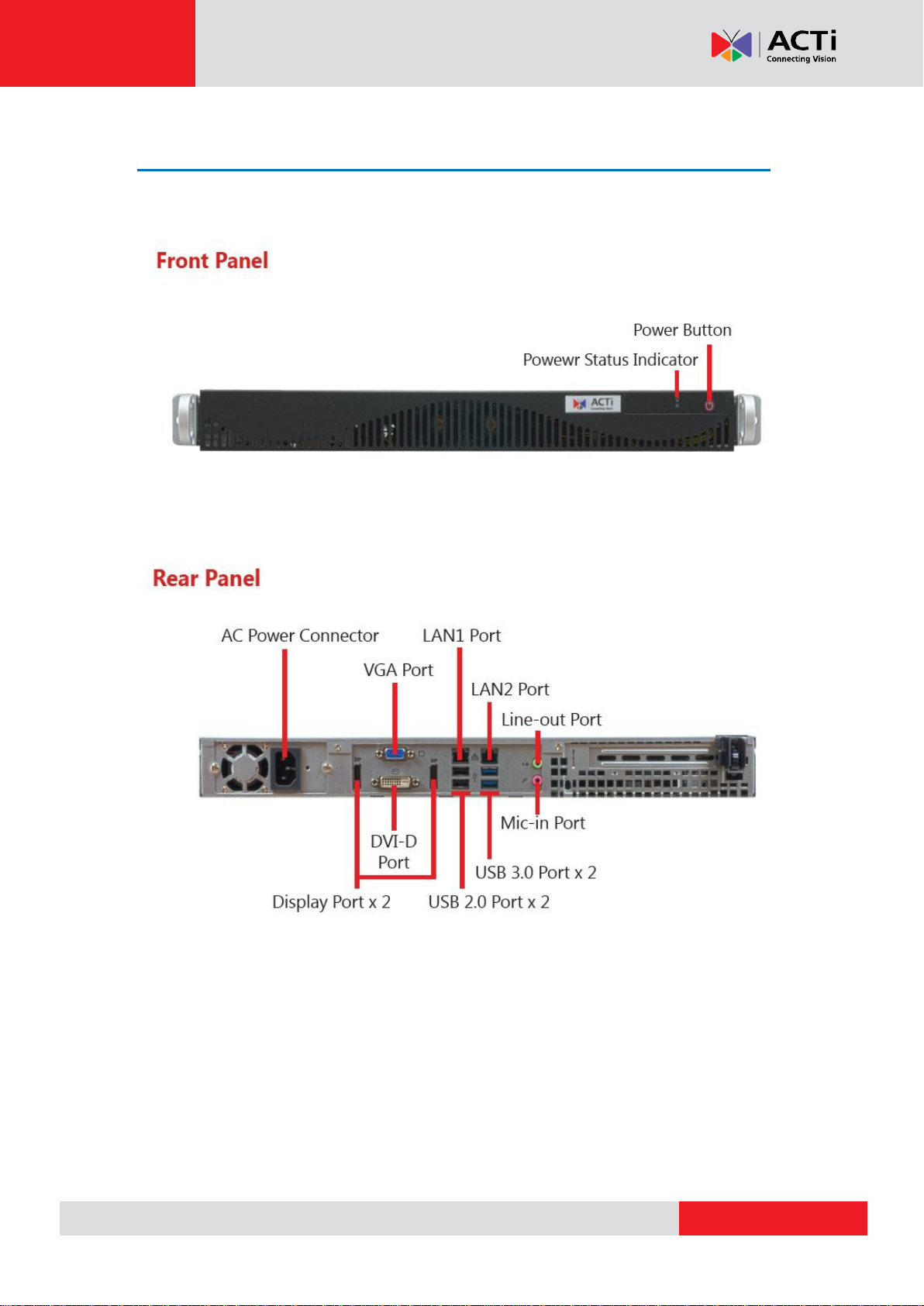
At a Glance
CMS-200 System Administrator’s Manual
14
Page 15

www.acti.com
CMS-200 System Administrator’s Manual
4
1
2
3
5
Connect the Devices
The example below displays a network consisting of only CMS, network cameras and required
peripherals. Please remember to enable the DHCP service on your router for CMS to obtain an
IP address automatically.
1. Connect the VGA monitor using the VGA cable supplied by the monitor manufacturer.
2. Connect the USB devices (e.g. the mouse, the keyboard or the joystick) and the audio
devices (e.g. the microphone and the speaker) to the audio output and audio input.
3. Attach the network cable to one of the LAN ports.
4. Plug the power cord into CMS and the electricity outlet.
5. Connect CMS with another network segment (e.g. remote client connection, SMTP
service) via the other LAN port (optional).
15
Page 16
www.acti.com
CMS-200 System Administrator’s Manual
Start and Turn Off the Unit
1. To start the unit, on the front panel, press down the Power Button panel, the Power
Status LED Indicator will light up and turn solid yellow.
2. To turn off the unit, press down Power Button, the unit will automatically shut down after
3~5 seconds.
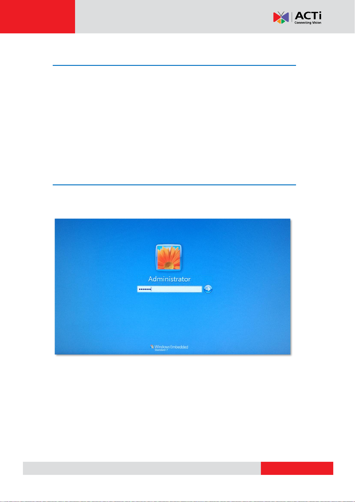
Enter Windows
After the unit starts, key in “123456” to log in as Administrator to Windows Embedded 7
system.
16
Page 17
www.acti.com
CMS-200 System Administrator’s Manual
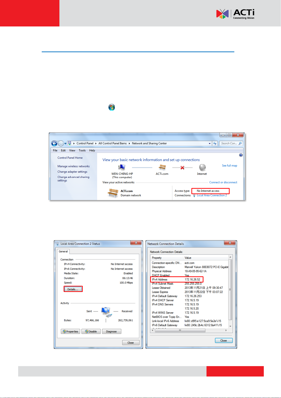
Configure the IP Address
After CMS starts, the network interface cards in it will be assigned IP addresses with the
DHCP service in the network.
Find the IP Address of CMS
To check the current IP address assigned by DHCP service:
1. Click Windows Start menu and select “Control Panel”.
2. Enter “Network and Sharing Center”, select the network card connection. Click your
current Internet connection.
3. A Connection Status window will pop up, click “Details…”, you will find all the connection
properties of this current network adapter in the details, including you IP address – IPv4
Address.
17
Page 18
www.acti.com
CMS-200 System Administrator’s Manual
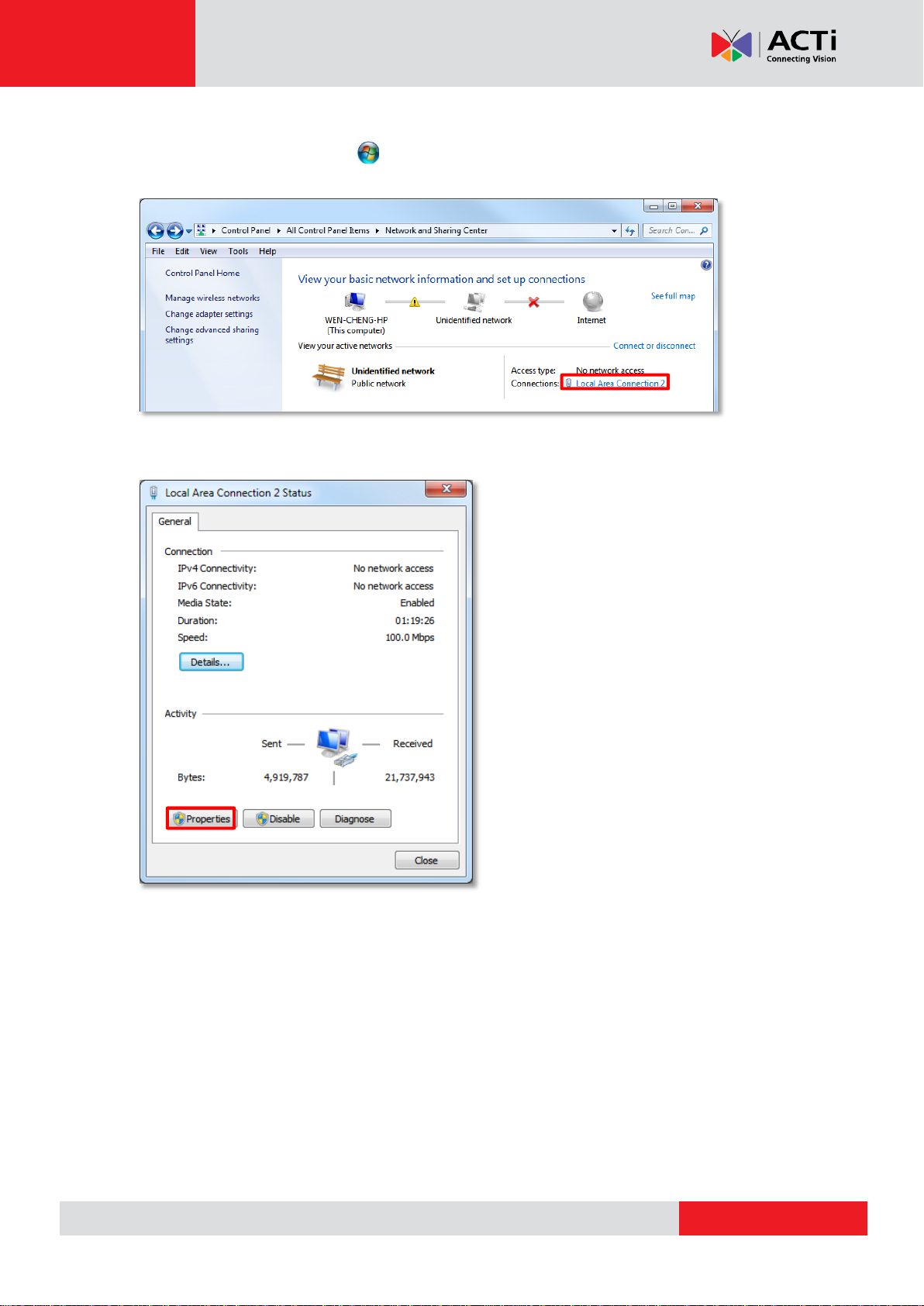
Assign a Static IP Address to CMS
1. Click Windows Start menu and select “Control Panel”.
2. Enter “Network and Sharing Center”, select the network card connection.
3. On Connection Status window, click “Properties
18
Page 19
www.acti.com
CMS-200 System Administrator’s Manual
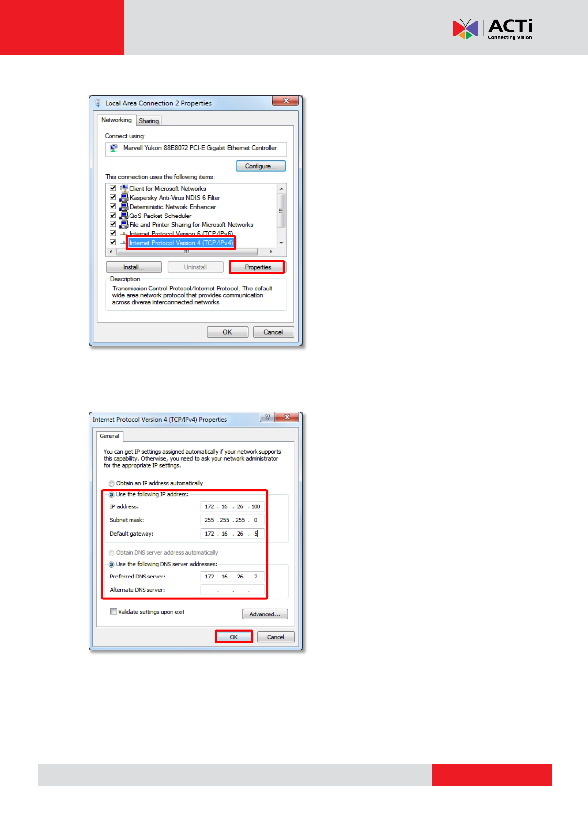
4. Select “Internet Protocol Version 4 (TCP/IPv4)" and then click “Properties”.
5. On Propertries window, select "Use the following IP address:" and enter the appropriate
values for the static IP address. Click “OK” to save the settings.
6. To change the current port number from 80 to another.
19
Page 20

www.acti.com
CMS-200 System Administrator’s Manual
Purchase licenses
from ACTi, get the
L
L
L
I
I
I
C
C
C
E
E
E
N
N
N
S
S
S
E
E
E
K
K
K
E
E
E
Y
YY
On CMS2 server, input the
L
L
L
I
I
I
C
C
C
E
E
E
N
N
N
S
S
S
E
E
E
K
K
K
E
E
E
Y
Y
Y
to activate the
license directly.
1
2
CMS-200
Log In to the System
License and Activation
In CMS system, the maximum number of channels is unlimited; your required number of
channels should be licensed and activated before adding the devices to the system. To get the
license, you may contact ACTi sales representatives to purchase the licenses and obtain the
License Key. Upon the activation of license with the License Key, the channels will
automatically become available.
Please note:
●The license is cumulative and perpetual.
●This unit is with 100 channel licensed bundled.
●The maximum number of channel license is 1600.
●The license is not version-specific, software version upgrading will not influence the existing
license you have activated on CMS server.
How Does License Activation Work
License activation is the process of unlocking the channels on CMS server with the received
License Key. License Key is a serial number delivered as a printed card or by email after the
purchase is carried out. During license activation, your License Key is matched against the
MAC address of the Network Interface Card (NIC) on CMS server computer. Once this license
key is used by the computer with given MAC, it cannot be activated with another MAC. This
matching record will be stored on the activation database. If your computer has more than one
network cards, CMS server will detect them and provide you a dropdown list to select from.
How to Activate the Licenses
There are two ways to activate the licenses depending on your CMS server network condition:
Online Activation
If your CMS server computer has available Internet access, you should take online activation.
20
Page 21
www.acti.com
CMS-200 System Administrator’s Manual
Step 1
: Membership ID in ACTi Member Center is
required for activation. Register one for free at
http://member.acti.com/
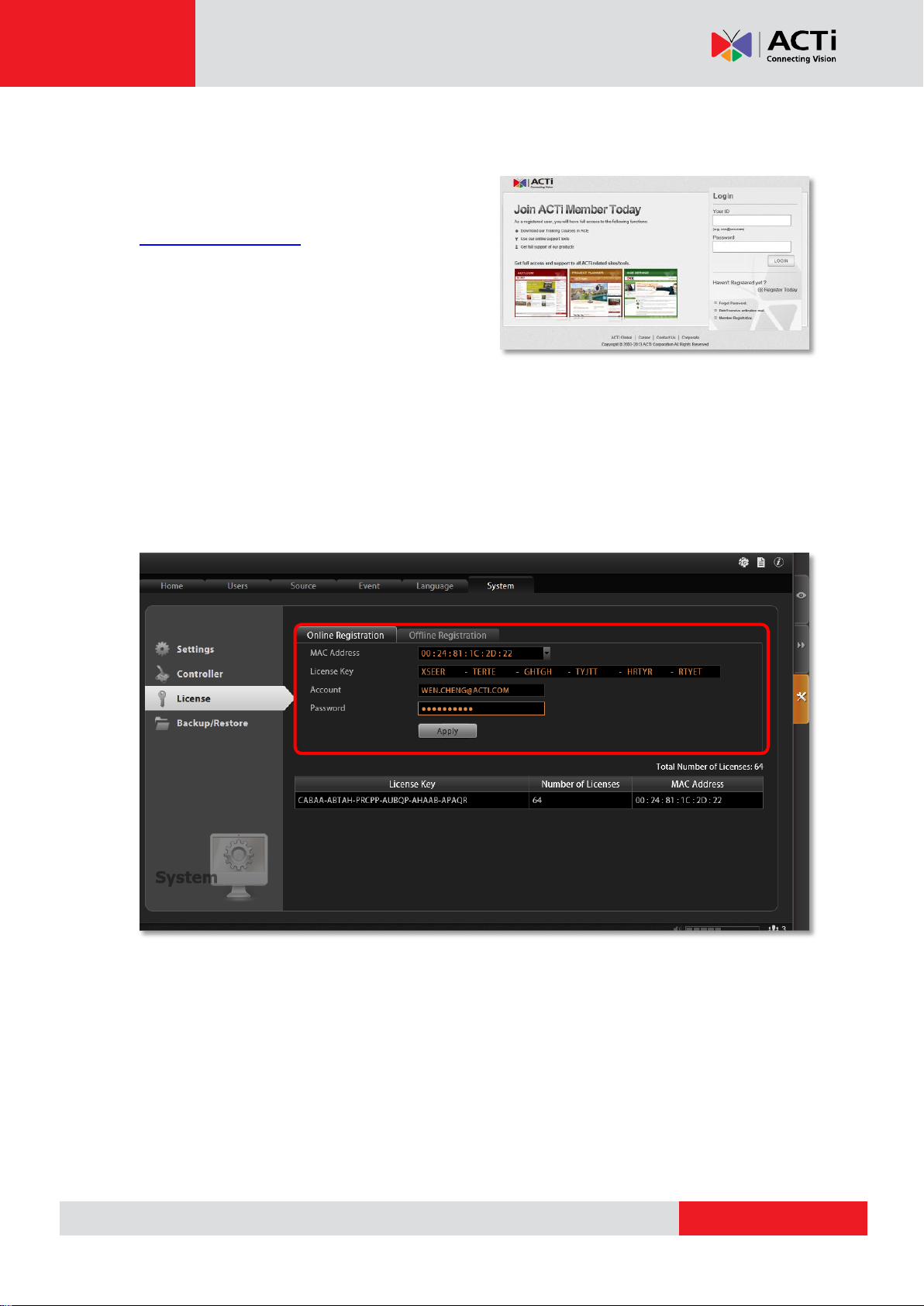
Step 2
: Log in CMS server, go to Setup pageSystem tabLicense“Online
Registration”. Select the MAC Address, enter your License Key, member Account and
Password, and then click “Apply”. CMS server will connect to the activation database via
Internet to register the license key, and unlock the channels.
21
Page 22
www.acti.com
CMS-200 System Administrator’s Manual
Purchase licenses
from ACTi, get the
L
L
L
I
I
I
C
C
C
E
E
E
N
N
N
S
S
S
E
E
E
K
K
K
E
E
E
Y
YY
On another computer, access
ACTi website to activate the
licenses using the
L
L
L
I
I
I
C
C
C
E
E
E
N
N
N
S
S
S
E
E
E
K
K
K
E
E
E
Y
Y
Y
1
2
Load the
A
A
A
C
C
C
T
T
T
I
I
I
V
V
V
A
A
A
T
T
T
I
I
I
O
O
O
N
N
N
F
F
F
I
I
I
L
L
L
E
EE
into CMS server
3
CMS server
Computer
(Internet access)
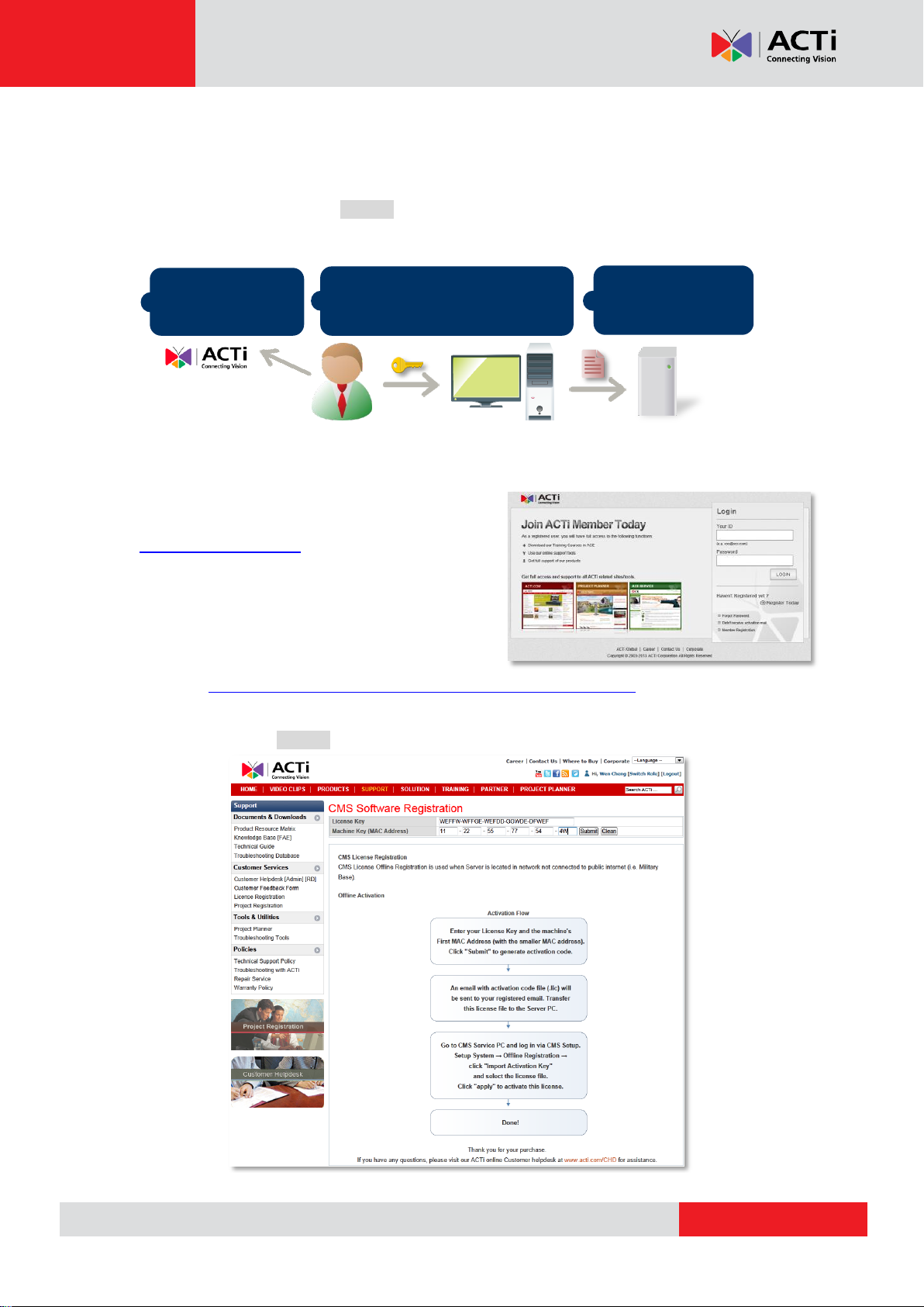
Offline Activation
Offline activation does not require Internet access for CMS server. It is used when CMS is
located in a network not connected to public Internet (e.g. in a restricted military base). You will
need to get an activation file (AUL.lic file) from another computer and transfer it to CMS server
computer.
1. Membership ID in ACTi Member Center is
required for activation. Register one for free at
http://member.acti.com/
2.
Access http://www.acti.com/support/LicenseMgt/CMS_registration.asp, enter the License
Key and the MAC address of CMS server computer, click “Submit”. An email with
activation code file (AUL.lic) will be sent to your registered e-mail account.
22
Page 23
www.acti.com
CMS-200 System Administrator’s Manual
Important Notice
The license data will be erased once CMS server is uninstalled. Be sure to retain your license key
information in a safe place because you may need to reinstall the software. After the software is
uninstalled, you should contact ACTi Customer Help Desk http://www.acti.com/CHD to clear the
original registration data in our database, and then you may activate the license again.
Tip
Tip
1. Click Windows Start, in the run box on Start menu, input “cmd”.
2. Execute the cmd program, and input the command “ipconfig /all” or “getmac”
3. The MAC address will be referred to as the Physical Address, made up of 12 characters
e.g. 00-1E-65-FE-8E-98
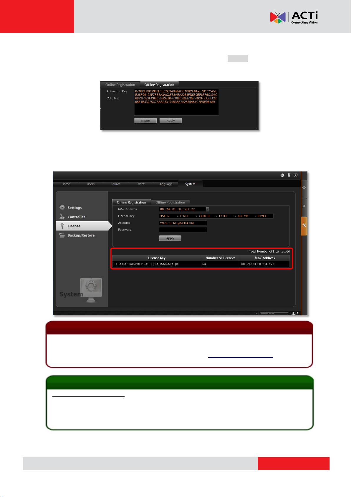
Activated Licenses
Important
3.
Log in CMS server from local or via web client. Go to Setup System tab License
“Offline Registration” click “Import” and upload the license file (AUL.lic). Click “Apply”
to activate this license.
Verify Your License
Once your license is successfully activated, the license information will be shown on License
page.
23
Page 24
www.acti.com
CMS-200 System Administrator’s Manual
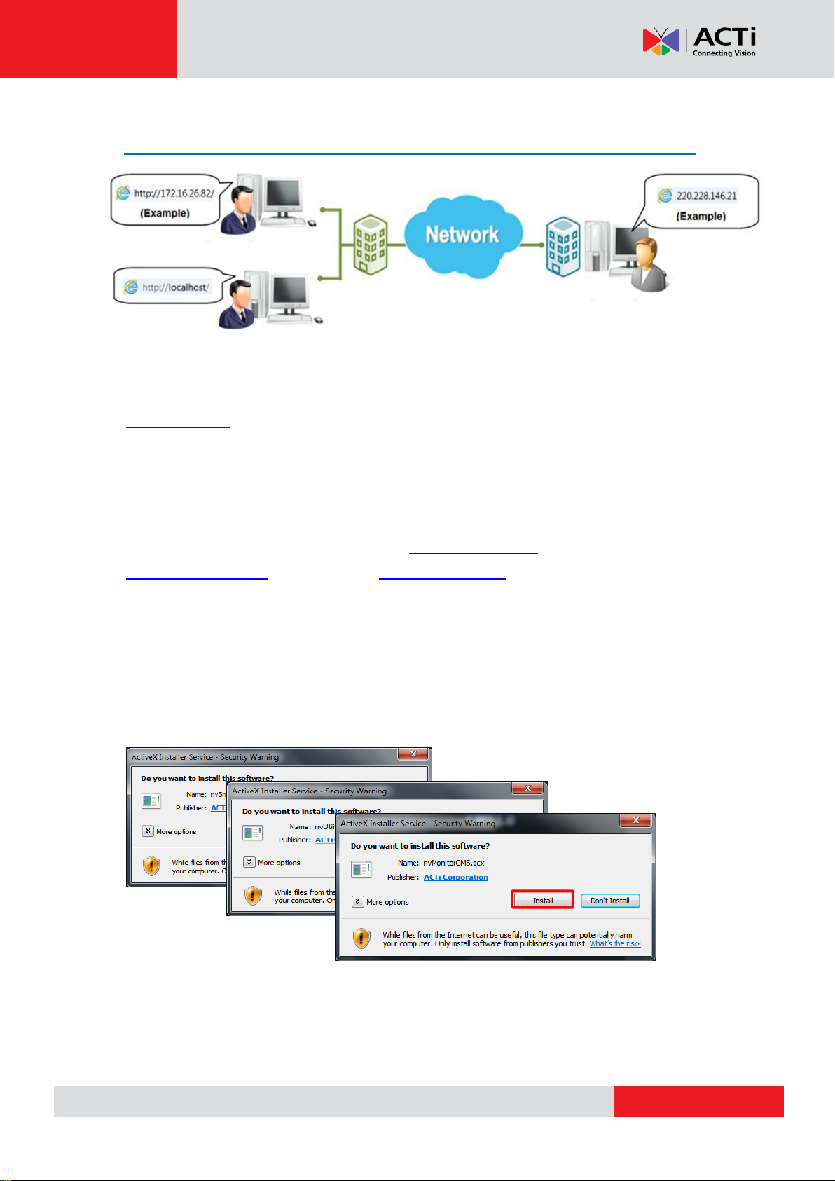
Access CMS Server via Internet Explorer
From Server Computer Using Local Client
Open Internet Expolrer. If your computer is where CMS server is installed, type
http://localhost/ or the computer’s IP address in URL box.
From Remote Client Computer
A remote client refers to any client using a computer over WAN or LAN other than server
computer. If you are connecting to a CMS server as a remote client, please type server
computer’s IP (e.g. local network ip: http://172.16.26.217 within LAN; public IP
http://220.228.146.21 or domain name http://cms.acti.com over WAN ) in URL box. If the
port number is 80, you can omit it when typing the address.
Accept ActiveX Controls Installation Requests
CMS interface requires the add-on ActiveX Control components, please make sure browser’s
security settings allow ActiveX controls to be downloaded and installed. When your browser
asks if you allow ACTi Corporation’s add-on components to run, please allow them.
24
Page 25

www.acti.com
CMS-200 System Administrator’s Manual
A B D
C
The email address input in Forgot
Password window should match
the one under your User account
saved in CMS server.
Login
A. Enter Account & Password
Account (non case-sensitive):
Admin (default)
Password (case-sensitive):
123456 (default)
B. Change UI language
To change UI language, select the desired
language from “Language” dropdown list.
C. Remember Account/Password
To have the server remember your Login Account and Password for future, check
“Remember Account/Password”. Clicking “Don’t Remember” will clear your input text and
reset to default.
To directly enter the main page every time you log in from this PC in the future
Check “Remember Account/Password” then “Auto Login” to skip the Login
page. If your computer may be accessed by someone without proper
authority, please DO NOT use either of these functions.
To cancel auto-login, on title bar, click “Logout” to return to login page,
and this function is cancelled.
D. Retrieve the Forgotten Password
CMS Server can send the password of the User’s account to the saved email
address. To have Users be able to use this service, please make sure (1) the
SMTP settings have been configured (refer to How to Setup SMTP Settings
for Event Rules on page 50) and (2) a valid email address has previously
been saved in Setup page Users tab User list.
25
Page 26

www.acti.com
CMS-200 System Administrator’s Manual
A C D E F G B
Access CMS Server via Workstation
CMS Workstation includes a set of programs that provide interface between users and the
CMS server. It may be installed on the same PC as the CMS server, or on a separate client
computer.
Double-click the shortcut icon on your desktop to execute this workstation
application.
Login
Fill in the following fields then click “Login” to log in to the system. The login process of
Workstation is very much the same as that of Web browser:
A. Server IP & Server Port
In Server IP field, key in localhost or 127.0.0.1
C. Choose the Initial Screen
CMS user interface consists of three main module screens: Live
if CMS Workstation is on the same computer
with CMS server. If you are connecting from a
non-server computer, please input the IP
address of server computer, for example:
220.228.146.22.
In Server Port field, key in the port number
(default is 80).
B. Enter Account & Password
Account (non case-sensitive)
Admin (default)
Password (case-sensitive)
123456 (default)
View, Playback and Setup, you may choose one where you would
like to enter after logging in. Default is Live View screen.
D. Language
Choose a UI language from drop-down list.
26
Page 27

www.acti.com
CMS-200 System Administrator’s Manual
E. Remember Login Information
To have CMS2 Workstation remember the Account, Password, your
choices of Initial Page and UI Language, simply check “Remember
login info”. Click “Don’t Remember” will clear your input text and reset
to default.
To directly enter the desired page every time you log in from this PC ,
check “Remember login info” then “Auto Login” to skip the Login page.
If your computer may be accessed by someone else, you might
consider not to use either of these functions.
To cancel auto-login, on title bar, click “Logout” to return to login
page, and this function is cancelled.
F. Retrieve the Forgotten Password
Please refer to D. Retrieve the Forgotten Password on page 25.
G. Server Name/Server Sites List
CMS2 Workstation can remember multiple server sites and their login settings and show the
site lists on Login window. To add a new site:
1. Click in the Server Name box and
input the server site name.
2. Fill in the other fields. If you disable
the “Remember Account/Password”,
then only the Server Name, Server IP
and Server Port of this server site will be
remembered.
3. Click “Save”
4. After a server site is saved, it will be
shown on Server Name dropdown list.
You may click on its name to enter its
Login window or to delete it from the
list.
27
Page 28

www.acti.com
CMS-200 System Administrator’s Manual
A
B
5. You can export the saved server sites, or import it to another Workstation client computer.
Access CMS server via CMS2 Workstation, go to Setup page System tab
Workstation.
A. Export current server sites list
Click “Browse” to select a folder to save the list, and then click “Export”. This file will be
saved as an *.xml file.
B. Import a server site list
Click “Browse” to select the *.xml file, and then click “Import”. The server sites will appear
in Server Name dropdown list on Login window of your next login.
28
Page 29

www.acti.com
CMS-200 System Administrator’s Manual
In this module, you can see live
view from NVRs, perform PTZ
operations with a mouse or a
joystick, view system log, receive
alerts on the event panel, set view
layouts, perform manual recording
or take a snapshot.
You may search and play existing
recordings in multiple channels
synchronously. Snapshots or video
segments can be taken from
playback files. Recorded files can
also be exported to AVI format here.
This module includes user setup,
NVR source/device setup, TV
Wall setup, event setup and CMS
system-wide settings.
Set up the System
This chapter will guide you through everything you need to know in System Setup procedure
from first time connection with CMS server to general system configuration.
CMS Main Screen
On the right are link buttons to three CMS major functions: (1) Live View, (2) Playback and (3)
Setup. You can click the orange button to enter the function page.
Live View
Playback
Setup
29
Page 30

www.acti.com
CMS-200 System Administrator’s Manual
Setup
Limited Group
Security Group
Monitor
Administrator
Group
Playback
Playback
Monitor
Manage Users
The User Groups/Users page allows you to (1) manage the access permissions of different
user groups, (2) add users to or delete them from user groups, (3) assign users to specific user
group. This chapter will take you through these settings.
Access Permissions
In CMS, the access permissions are managed by User Groups. User Groups defines which
CMS operations and NVRs are allowed for the group users. Different User Groups will have
different access rights. For example, an Administrator User is allowed for the complete
operations in CMS system, while a standard User may only be permitted to see Live View and
do Playback with limited NVRs. The chart below displays an example consisting of different
employees as CMS Users and their access rights in this system:
Overview
Go to Setup page Users tab. There are two sections to manage User Groups and Users
individually.
User Groups: To setup user groups and its permissions for device and functionalities.
Users: To manage user accounts and configure user information.
CMS has integrated Microsoft Active Directory® service to provide network administrators a
more convenient choice for user management. Active Directory is a directory service built in
Microsoft Server products to manage user identities and privileges within the domain network.
As CMS runs on a server computer logged on to the same domain with an Active Directory
30
Page 31

www.acti.com
CMS-200 System Administrator’s Manual
server, you can import a user account or a group from those concurrently existing in Active
Directory into CMS server. In this way, the user identification is processed by Active Directory
centrally, and there is no need for CMS administrator to maintain these user accounts.
User Groups
You can specify access permissions to each NVR for an entire user group. This user grouping
can save you significant amount of works if you have multiple users performing similar tasks
and acting as similar roles.
There are already two default User groups
Administrator: With full permissions in CMS interface.
User: With the permissions to watch all camera live view and playback(Default).
The Administrator User is predefined with full permissions in the CMS server, and cannot be
deleted. You can choose to create a new user group on CMS server or import an existing
group from the Active Directory database within your domain.
1. Select , click “Add” and then choose the group type:
Add a new user group:
Insert ID, group Name and group Description, your input in the Name field will be the
name of this User group. Click “Apply” to finish.
Import a domain group as a User group:
Choose an existing user group from your domain, and click “Apply” to finish.
31
Page 32

www.acti.com
CMS-200 System Administrator’s Manual
Live View page
Playback page
CMS Setup page
Domain users added as a whole group
The domain users within that group will all be added to CMS server at the same time. To view
the whole users within this group, please select and enable the “Show
users in domain groups.” The account information of these domain users, unlike those user
accounts you add one by one to CMS server, are not editable on Users page.
2. Assign CMS Permissions for created group. This will define what functions this User
group is allowed to access. By default, a User group will initially be allowed to access only
Live View page and Playback page on CMS, but without any permission to CMS or NVR
settings, so you may have to assign the Source Permissions later.
3. Assign Source Permissions for created groups. This will define which NVRs this User
group is allowed to access. If this User group is allowed to access later-added NVRs, check
“New Source Default” and edit the permissions.
32
Page 33

www.acti.com
CMS-200 System Administrator’s Manual
New NVRs
Existing NVRs
You may individually check the NVRs this user group is allowed to access, and set the
permissions to configure NVR settings.
You may also enable the permissions related to a specific camera under the NVR.
Instead of tailoring the settings for each device, you may click “Device Unified Settings” and
set universal settings, which will be applied to any device you check under this NVR.
You may copy the Source Permissions Settings to other sources. Click “Copy” under
Source Permissions tab to bring up the target NVR menu, check the target sources, and click
“Apply”.
33
Page 34

www.acti.com
CMS-200 System Administrator’s Manual
Click “Apply” on the top to save the settings.
Add Users
To create a user account with on CMS server.
1. Select , and click Add button.
2. Select User Type as Customized User or Domain User.
Customized User: an account created and managed on CMS server only. You will input
an account name, its password and e-mail address for this User.
Domain User: an account that already exists in Active Directory database within the
domain. Since this is an existing account in your domain, you will have to select this
account from Account dropdown list.
3. Insert user account, name, password, and the account e-mail (For Customized User).
4. Assign this created user account to a specific user group.
5. After you click “Apply”, this new user will be added to the list on the top.
34
Page 35

www.acti.com
CMS-200 System Administrator’s Manual
Note
Account /Password Rules
1. Account and Password fields allow alphabets, numbers, and symbols except the
following: / \ [ ] : ; | = , + * ? < > "
2. In Account field, for alphabets, the input will be recognized as lowercase letters. Space
is only allowed between characters; the space in the beginning or at the end will be
deleted when it is saved.
3. The Password field is case-sensitive, and the space is allowed.
Note
Admin is the default user account and belongs to “Administrator” user group. Hence, the
user Admin and its group Administrator cannot be deleted; it possesses full permissions to
all NVRs, devices, and CMS settings.
CMS server provides a procedure to help Users who have forgotten the password retrieve
the original information, which relies solely on the “e-mail address” authentication. It is
strongly recommended that you input an e-mail address that this User has access to when
you establish the User account. To update the e-mail address of an account, go to Setup
page Users tab edit “Email” of an selected User account; the Users can also update
the e-mail addresses themselves after logging in to CMS on Live View page
Update Profile
Note
35
Page 36

www.acti.com
CMS-200 System Administrator’s Manual
Domain:
ACTi.com
Active
Directory
Domain
Controller
ACTi CMS
2.0 Server
Domain Users Management
As CMS server computer is logged on to a domain Active Directory, it can import a user
account from Active Directory.
This type of User account is “Domain User”. Upon being added to CMS server, the User
properties stored on Active Directory database including account name and e-mail address will
be imported to CMS server.
Whenever the Domain User client tries to log in to CMS server, CMS server will first verify if
this account exists in CMS server database, if not, it will then have Active Directory verify the
user account and password.
As Active Directory owns the privilege to create, edit and delete domain users, the Domain
User’s account and password are not editable through CMS user interface but via
Active Directory Administrative tool.
36
Page 37

www.acti.com
CMS-200 System Administrator’s Manual
No NVR
Manage NVRs
A CMS server manages multiple NVR severs, whose fundamental building blocks are the
cameras or video encoders. The first thing you should do after you have registered the license
is to setup your NVR connections in CMS Setup page. In this section, we will guide you
through how to manage the NVRs and their devices.
Add an NVR
To start adding a new NVR, please follow steps as below:
1. On Setup page click “Source”. There is no source in All Sources list. Now click “Add
Source”.
2. On the Add Source window, fill in the following
fields and click “Apply”:
●Name - title of this NVR
●Host - the NVR’s IP address
●Port - the NVR’s port number
●Password - the Administrator’s password of this
NVR. By default, all the devices in the NVR will be
automatically added to CMS server after you click
“Apply”. If you want to select only the desired
devices rather than import all the devices at this
stage, de-select “Auto Import All Devices in
Source” before clicking “Apply”.
37
Page 38

www.acti.com
CMS-200 System Administrator’s Manual
Added NVR
Imported Devices: All
Imported Devices: None
Import Devices from NVRs
In most cases, with limited licenses, you do not import all devices of all NVRs to your CMS
server. After an NVR is added, you may start selecting your desired devices to be imported
to CMS server. Once a device is imported, on CMS interface you can (1) modify this device
directly, (2) see its live stream ,(3) receive the instant event notifications from this device and
(4) watch the recorded video of this device.
1. On All Sources list, select this NVR, the Using Devices list on the right will display the
imported devices. By default, all the devices of an NVR were already imported as you
added it to CMS server.
2. If you have unchecked the box “Auto Import All Devices in Source” when adding this
NVR source, you have to select the devices to be added by yourself.Click “Import Devices”
to enter NVR device list.
3. On the Import Devices list will show all devices of this NVR. Select the desired devices you
38
Page 39

www.acti.com
CMS-200 System Administrator’s Manual
Imported Devices: 2 and 4
Selected Devices:2 and 4
Tip
Whenever your CMS server loses connections with certain devices, it is always suggested
that you click this button first, since the loss of connection probably resulted
from some changes done on the NVR site.
want to import and click “Apply”.
4. The Using Devices list will be updated in accordance with your selection on Import
Devices list.
Synchronize Device Settings
The configurations done on NVR site will not be synchronized with CMS server actively. For
example, an NVR administrator may replace several cameras (which have also been imported
to CMS server) with new ones, and therefore the CMS site would lose the connections
between those replaced cameras. On CMS site, you can synchronize with an NVR server via
one click:
1. Go to Setup page Sources tab, on All Sources list, select this NVR.
2. On the right, click “Sync Devices” button.
3. Click “Apply”.
39
Page 40

www.acti.com
CMS-200 System Administrator’s Manual
Tip
You may turn off the status display of an NVR server and its devices shown in the Source
Setup List. On Source tab, select the NVR server under All Sources list, and de-select
“Receive Event Message”
Manage Multiple NVRs
You may centrally manage multiple NVRs on the All Sources Setup List easily.
Go to Setup page Sources tab. Under lists all the NVRs you added.
Search an NVR
To locate a specific NVR in the All Sources tree, you may input the keyword in its name in the
search bar, click to start searching, and click to show all sources.
Delete NVRs
Highilight , a list of connected NVRs will appear on the right. Select the NVRs
you want to delete, and click “Delete” then “Apply”.
Synchroinze with All Devices
Highilight and click “Sync All Devices”, CMS server will synchronize with all
the NVRs and imported devices.
40
Page 41

www.acti.com
CMS-200 System Administrator’s Manual
NVR User Group/Permissions management
NVR User Account management
NVR Storage setup
NVR System setup (Email/SMTP/FTP/Export folder/UI style)
NVR License management
NVR Backup/Restore/Language file management
NVR Device list
Add Devices to this NVR by auto-search or manually
Configure NVR / Devices Settings
As CMS administrator owns unrestricted rights to control all the NVRs and their devices, it is
sometimes more convenient to modify the NVR settings directly from CMS interface. On CMS
Source management page, you may change any property of an NVR or its devices.
NVR Settings
To enter an individual NVR’s settings, Go to Setup page Sources tab, on All Sources list,
select an NVR, and click on the arrow to expand its sub category. By selecting a title,
the setup page will appear on the right. Any change applied to the NVR will be saved to both
NVR itself and CMS server.
Device Settings
To configure the settings of a device, select the device from Source Setup List, and modify
the available settings on the right.
41
Page 42

www.acti.com
CMS-200 System Administrator’s Manual
Note
Please note the following before applying any change to an NVR server:
1. It is strongly recommended that you make a backup of the original NVR settings.
2. Only the devices in the same network segment with the selected NVR can be found or
manually added by clicking “Add Device”.
3. To modify a device’s schedule or event rules, please select the device and enter the
Schedule or Event tab on the right.
4. The customized views saved on an NVR server cannot be configured via CMS interface.
5. ENR system settings and storage settings are accessible only via ENR interface.
42
Page 43

www.acti.com
CMS-200 System Administrator’s Manual
Example Icon
Status Description
Video loss:
CMS cannot retrieve the video stream.
Modification has not been saved:
This device’s settings have been modified but not saved yet. If you leave
these modifications unsaved, they will not take effect.
Connection loss:
CMS cannot build up connection with this NVR or device. Please check the
connection settings (including IP Address, Port number, Account Name and
Password); or increase the “Connection Timeout” to allow more time for
the device or NVR to respond.
Disk Full:
The storage space of this NVR server is full, and no recording is taking
place. You will need to go to Setup Source tab and configure the
Storage settings in Source Setup List.
Recording:
This device is currently connected, and video is being recorded either
manually or according to the schedule. The orange “SD” sign indicates that
this device supports local storage.
Connected:
This device is currently connected, and the video stream is viewable on
Live screen.
You have blocked the system event messages sent from this server, which
means the current status of this server is invisible now.
Status Icon Description
On Live View screen or Setup page Source tab, the icons shown under All Sources
category will display the status of each NVR server as well as the devices.
43
Page 44

www.acti.com
CMS-200 System Administrator’s Manual
CMS Event Rule
Motion is detected!
Server disk is full!
Camera
NVR Server
CMS Server
Beep Alert
E-mail
Event Management
Under CMS’s management, an event detected by a single device can be notified not only to
the NVR clients but to CMS clients at the same time. For example, once a camera detects a
motion, both an NVR client and a CMS client can receive the alerts via emails. To do so, you
have to set even rules in CMS Setup page Event tab. The event rules set here will be
independent from those set on NVR.
44
Page 45

www.acti.com
CMS-200 System Administrator’s Manual
How to Edit an Event Rule
Go to Setup page Event tab. All the editable event rules are listed on the right.
NVR Status Event Rule
An event rule set for an NVR will trigger actions to notify CMS client.
1. Select an NVR source to edit an NVR event rule. There are seven types of NVR status that
can be set as event triggers – Source Loss, Source Recovery, Schedule Service Start,
Schedule Service Stop, Disk Full, Disk is Available and Disk Not Found.
2. Highlight the rule you wish to edit. Double-click the “Response” field to edit the
response action.
3. On Event Edit window, you can enable multiple response actions by first checking the
box(es) to enable the items:
45
Page 46

www.acti.com
CMS-200 System Administrator’s Manual
Action Items
Function Description
Set to play beep sound for a number of
repetitions.
On CMS2 Workstation client computer,
you can upload a WAV file or an MP3 file
as the alert sound, and set how many
times this audio file is play when event
occurs.
Beep and Audio file responses cannot
be executed at the same time.
Enables CMS server to execute a specific
command upon this event. You can use it
to integrate CMS event with other
programs. Enter the path of the command
to be executed upon event.
Enables CMS server to send an email
notification via SMTP server. The default
SMTP and sender’s e-mail settings can
be set in advance in
Setup page System tabSettings
Email& SMTP Settings.
1. Type one or more recipients’ email
addresses in “To” column (if more than
one, please separate them by “;”
symbol) or click the icon to select
recipients from existing NVR User list.
The User’s Email address should be
set in advance (in Setup pageUsers
tabUsers) so that it can be selected
in this list.
2. Edit the e-mail subject and content.
46
Page 47

www.acti.com
CMS-200 System Administrator’s Manual
Action Items
Function Description
This kind of action will focus your
attention on the channel on client’s Live
View page when triggered.
Pop-up:
Brings up event pop-up playback window
of selected channel upon trigger. You may
also define the display duration of video
on the window.
Hot-spot:
Displays video in Hot-spot window (red
flashing frame) upon event. You may also
define display duration of video on the
Hot-spot window
You may also define duration of the
temporary View. Only Public Views are
selectable for Switch View event rule.
Device Status Event Rule
An event rule set for a specific device will trigger actions to notify CMS client.
1. Select an NVR, click the arrow to expand its sub-categories, and select the device.
There are five types of device status that can be set as event triggers – Motion, DI Trigger,
Video Loss, Video Recovery, Network Loss and Network Recovery.
2. Highlight the rule you wish to edit. Double-click the “Response” field to edit the response
action.
3. On Event Edit window, you can enable multiple response actions by first checking the
box(es) to enable the items:
47
Page 48

www.acti.com
CMS-200 System Administrator’s Manual
Switch View:
The current Live View will be switched to
another one for a while. To enable this
option, you will need to customize and
save Views on Live View screen first.
Hot-spot and Switch View responses
cannot be executed at the same time.
Makes CMS client computer play beep
sound for a number of repetitions.
On CMS Workstation client computer,
you can upload a WAV file or an MP3 file
as the alert sound, and set how many
times this audio file is played when the
event occurs. (This CMS server has to be
already on Server Site list, see G. Server
Name/Server Sites List on page 27)
Beep and Audio file responses cannot
be executed at the same time.
Pushes any of the following to a
designated TV Wall monitor: a specific
live view of a device, a customized CMS
View, all devices of an NVR, or a TV Wall
View Set to. Please check the box
“Enable” first to enable this configuration:
Send live view of a device
Select Type as “Device”, the NVR
Source and the Device name, define
how long this live view will stay on the
screen, and click the monitor from the
Target TV Wall station you select on the
right.
Send live view of all devices
Select Type as “Source” and the NVR
Source, define how long this live view will
stay on the screen, and click the monitor
from the Target TV Wall station you select
48
Page 49

www.acti.com
CMS-200 System Administrator’s Manual
Send a CMS View
Select Type as “View”, the name of the
View Group, and the View name, define
how long this live view will stay on the
screen, and click the monitor from the
Target TV Wall station you select on the
right.
Send a TV Wall View Set
Select Type as “TV Wall View”, the TV
Wall station, and the name of the View
Set, at last, define how long this live view
will stay on the screen.
To validate if this rule is successfully set, please make sure you have properly configured the
involved settings like Motion Detection Regions or hardware devices like an audio speaker.
Manage the Event Rules
Event List panel gives an overview on event rules set on the CMS server. Go to Setup page
Event tab select All Sources on the left. As the entire available rules of all NVRs are
listed here, you may want to sort out some of them from the long list.
View the Event Rules
To sort by NVR Source name or Event Name, click the titles to list the entries in ascending or
descending alphabetic order; another way is to click an NVR source of a single device in
Source Setup List to view their own event rules.
49
Page 50

www.acti.com
CMS-200 System Administrator’s Manual
Field Name
Description
Server
Input the sender’s SMTP server address. Only alphabets, numbers, and the
symbols (.), (_), (-) are valid.
SMTP Port
Set the SMTP port, allowed value is from 1~65535, default is 25.
Account
Input the name of the SMTP server account. Only alphabets, numbers, and the
symbols (@), (.), (_), (-) are valid.
Password
Input the password of the SMTP server account. Only alphabets and numbers
are valid.
Security
Certain webmail providers provide the SSL/TLS-encrypted SMTP connections
to secure your data when sending/receiving e-mails. Please check if the SMTP
Delete the Event Rules
On Event List, select the rules you wish to delete, and then click “Delete” to clear this rule.
How to Setup SMTP Settings for Event Rules
CMS supports email notification sent through an SMTP server. You can specify the email and
server settings here.
1. Go to Setup pageSystem tabSettings Email& SMTP Settings.
Fill in each of the following fields.
50
Page 51

www.acti.com
CMS-200 System Administrator’s Manual
connection settings you use (especially the SMTP Port) now require to enable
either SSL or TLS.
Sender Name
Input the name or title of the sender. You may input a name different from the
account name.
Sender Mail
Input the sender’s e-mail address, which should be the same account you set
for SMTP server.
2. As all necessary information is filled in, click “Send Test Mail” to try sending an email
according to your settings, and then log in to your SMTP server to check incoming
emails. If the test mail is sent successfully, CMS server is ready to send out emails.
3. As the settings are confirmed, click “Apply” to save.
51
Page 52

www.acti.com
CMS-200 System Administrator’s Manual
System Log
The activities performed by logged-in Users are recorded on server as System Log. With the
access permission, a user may view, search and export this record for analysis or investigation.
This section will provide the instructions on how to read and search data in the system log.
“System Log” is one of the resident buttons on top of CMS server user interface, click it to
enter either “CMS System Log” or “NVR Source System Log”.
CMS System Log
Upon entering the log page, you will be provided with a blank result list. After you define the
searching criteria and click “Search”, the CMS System Log will search the activities
performed on CMS.
To start, please define the search criteria.
52
Page 53

www.acti.com
CMS-200 System Administrator’s Manual
Search Time
The default is your current client time.
Log Type
You may filter the logs by activity Type. By default, all types are selected.
User Account
You may filter the activities performed by a specific user.
NVR Source / Device
You may filter the activities related to a specific NVR or a device.
53
Page 54

www.acti.com
CMS-200 System Administrator’s Manual
Note
If the pagination button appears to be disabled, that means no more records are found on
CMS server. By default, the server will keep the logs for 30 days. If you wish to adjust the
period, please go to Setup page System tab Settings, in System Log Settings
section, key in the value in this field:
Read the Log
The search result will show 1000 records before and after your query time. You may click the
pagination buttons to navigate earlier or later records. If there is an icon on the top
right corner of an entry, click it to view the full description content.
A log entry contains several kinds of information including Date Time, Type, User Account,
Source, Device and Description. Check Type and Description fields to know what the user
has done or what happened to the whole system. In Type field shows what major functions this
behavior was involved in, in Description field narrates how the change was done (in green
font color, uppercase) and the result (in white font color).
Take the case below for example, you can tell that the admin user set up an event rule on
2013/4/25 for #1 device(11F_Entrance) on #2 NVR(MobileGo) to trigger a response upon the
motion detected by #1 device(11F_Entrance)’s motion region 1.
54
Page 55

www.acti.com
CMS-200 System Administrator’s Manual
Export the Log
Click “Export” button to export the log as .csv file. You can specify the Time Duration, NVR
Source, User Account and the involved Device of the logs, and click “Apply”.
NVR Source System Log
As the CMS administrator owns the same privileges of an NVR administrator, it is able to
acquire the NVR system log from CMS interface. Unlike CMS System Log, NVR Source
System Log records an NVR user’s activities on NVR. Click , enter Source System Log,
specify the NVR Source name and other criteria, CMS will start searching.
55
Page 56

www.acti.com
CMS-200 System Administrator’s Manual
View List
Source List
CChhaannnneell
VViieeww
4 3 1
2
VViieeww TToooollbbaarr
Customize Views
After all NVRs and devices are added, you may start customizing the views for different users
and purposes. This chapter will teach you how to add video source, arrange the channels and
manage live view layouts.
In CMS system, a View refers to the layout where the live images of Cameras or Maps are
placed in proper positions to suit the monitoring purpose. This is very similar to a camera
group, which often consists of cameras in the same physical location. For example, a View
named 11F Emap & Camera may contain the 11F floor plan and the cameras actually placed
on 11F.
On CMS Live View, a saved View not only remembers (1) layout style, (2) which channel to
display which camera, (3) but the fisheye view mode (for fisheye cameras only.
Live View Interface Overview
1. View Toolbar: Provides 24 options for layout styles and the functions keys for editing
a view.
2. Channel: Each channel window may display a camera view or a map. In edit mode,
you can adjust the channel size at will.
3. View List: All the saved Views are shown here. On Live View, you can go to
View Manager to group and manage these views (refer to Manage the Views on page
63).
56
Page 57

www.acti.com
CMS-200 System Administrator’s Manual
4. Device List: In edit mode, drag a camera from here to your desired channel.
Step 1: Create a New View
On View Tool Bar, click the Create View button , input the View Name, add a New
Group for this View and decide whether this group is to be Public or Private, and then click
“Apply”.
The views under Private View Group are only available to the User who created them.
The views under Public View Group are open to every User.
Step 2: Enter Edit Mode
On View Toolbar, click the Edit View button , this view will turn into edit mode. In edit
mode, you may add a video source to a channel, and adjust the channel size.
Step 3: Select a Layout
On View Toolbar, click the Expand button to find all provided layout styles. Select a
layout that is perfect for your required channel number and ideal arrangement.
57
Page 58

www.acti.com
CMS-200 System Administrator’s Manual
Step 4: Add Video Source
In edit mode, move the mouse over the channel
and click to select a camera from the source
list. You may also directly pull a camera from the
Device panel to your desired channel.
Remove the camera view: right-click on the channel and select “Remove”.
Step 5: Add a Map
By adding a map, you put a picture on the channel, where you may place camera icons later to
make it an “e-Map.
In edit mode, move the mouse over the channel
and click to upload a map. Please input the
Map Name, select the image location (file format
must be JPG) and click “Apply”.
58
Page 59

www.acti.com
CMS-200 System Administrator’s Manual
Map brightness:
To change the map brightness, right-click on the map, select
“Map Mask” and the brightness percentage level.
Map size:
By default, the map will be displayed
in its original size. Use the button s on
upper right to adjust the map size.
Enlarge to fill channel height
Original image size
Zoom in
Zoom out
Edit map title:
The map title will be shown on channel title bar. In edit mode, right-click on a map channel and
select “Edit Map Information”
59
Page 60

www.acti.com
CMS-200 System Administrator’s Manual
To remove this device from map:
Click
To move this device:
Left-click on the device icon and drag.
To change the pointed direction:
Mouse over the viewing angle area, left-click on the
clockwise arrow to turn the direction.
Remove the whole map:
Right-click on the map and select “Remove”.
Manage maps:
All the uploaded images are managed under Map Image Manager. On Live View screen, you
may go to Map Image Manager to view, upload or delete the maps.
Step 6: Add Devices to the Map
Pull a device from Device List to the map.
60
Page 61

www.acti.com
CMS-200 System Administrator’s Manual
To adjust precise pointed direction:
Right-click on the device icon, select
“Pointed Direction”.
To adjust device’s viewing angle:
Right-click on the device icon, select
“Vision Angle”.
If this is a device of an NVR3 server (including GNR-3000 server, INR-410 server or INR-420
server) and its stream mode is set to DUAL or multi-streaming, you can choose a desired
stream from View Toolbar. This choice of stream will be remembered by this View.
Step 7: Adjust the Channel Size & Layout
Adjust the channel size:
Click on right lower corner of the channel window, drag and then release.
Switch channel windows:
Click on a channel title until the cross arrow
appears, hold it to drag this device or map to your
desired channel.
61
Page 62

www.acti.com
CMS-200 System Administrator’s Manual
8 directional buttons
Zoom in / Zoom out
ePTZ Controls on PTZ Panel
Step 8: Save the View
Click on View Toolbar to save it.
Step 9: Set Default View
To set a View as default, select it in the View List panel and then click on View Tool
Bar. By next time you log in, you will directly enter this View.
Step 10: Set Default Hotspot Channel (Optional)
By system default, the global hotspot channel will always be the top left one. You can set any
other channel on your live view screen to be the default hotspot channel. Right-click on the
channel and select “Default Hotspot” , then click on View Tool
Bar to save it.
Step 11: Set Fisheye Camera Mode
Define a view for a fisheye camera channel by selecting its mode and using ePTZ control.
Please note that the maximum number of fisheye channels on the same View is 16.
1. On this channel, right-click to bring up channel menu, click “Fisheye Mode” and select
one mode.
2. After the fisheye mode is selected, click a region of interest.
Use PTZ Panel controls to operate PTZ movements:
Click the mouse anywhere on the view to pan/tilt, scroll the mouse wheel to zoom
in/out.
62
Page 63

www.acti.com
CMS-200 System Administrator’s Manual
4
5
6 7 2
3
1 2 4 5 1
3 6 7
Zoom in
Zoom out
Pan/Tilt
Note
Once a channel is changed to any of the following fisheye modes: Dewarping, Panorama,
Double Panorama, Panorama/Focus or Quad, the resolution of this live stream will become
1920x1080, while NVR still records the live stream at the resolution you set on Setup page.
To reset the ePTZ navigation area back to default viewing angle, right-click to bring up
channel menu, and then click “Reset”.
3. click on View Tool Bar to save the configuration.
Manage the Views
Each View belongs to a specific View Group. With the group management, CMS makes it
easy to deal with Views you created for multiple Users.
After you created and saved the Views on Live View screen, click View Manager.
1. Click on the arrow icon in front of a group folder to reveal its Views.
2. By selecting a View, you may directly modify its name in Name field.
3. You may change a group’s Group Type. Upon the change, for example, by changing a
group from “Private” to ”Public”, all the views belonging to it will be open to every User.
4. Click this icon to add a new group.
5. Click this icon to delete a selected group.
6. Click this icon to copy a selected group to another group.
7. Click this icon to move a selected group to another group.
63
Page 64

www.acti.com
CMS-200 System Administrator’s Manual
Set View Link
By creating a link button on a map view, you can directly be linked to another view. On the
picture below shows how to create a link button to 7F View on 11F map.
1. Select a map View, on which you will place a link button to another view.
2. Click on View Tool Bar to enter edit mode.
3. From View List, drag the target View to current View, a link button will appear.
4. Click on View Tool Bar to save it.
Set View Patrol
You may have the saved Views patrol in turns. In this way, the views in different area in your
site may cycle through themselves for you automatically.
64
Page 65

www.acti.com
CMS-200 System Administrator’s Manual
On View Tool Bar, click then Create Patrol.
1. Input the Patrol Name.
2. Select the Patrol Type to be open to all Users or to the creator only.
3. Define the Global Dwell Time between the views. If you want to set different dwell
time length for individual Views, do not check this option, and configure them
separately in below table.
4. Choose the Views to display in patrol. If you select the All Sources group, you will
also need to select “Source Layout Style” for it.
5. Click “Apply” to save the settings.
6. The saved patrols will be shown on the patrol list
after you click on View Tool Bar, you may
delete and edit a saved patrol or select it to start
patrolling.
65
Page 66

www.acti.com
CMS-200 System Administrator’s Manual
Tips to Enhance Live View Performance
Live view for multiple channels requires sufficient computing power to run the performance.
In certain extreme cases, like when viewing several megapixel H.264 video streams at the
same time, client computer will be overloaded and hence affect browser’s performance. This
is a common limitation imposed upon all Windows based video management programs and
web browser.
To enhance live view performance, below are several tips you may try:
1. Use another browser client to share these high-resolution channels. Given that there are
32 megapixel channels to be monitored, you may have Layout 1 to display channel
1~16, set Layout 2 to display channel 17~32, then open one browser client to show
Layout 1 and the second browser on an extended monitor to show Layout 2.
2. Have CMS automatically lower the frame rate of live streams when system loading is
high. Go to Setup page System tab Settings Display Performance Setting
and enable this function. Basically, this setting will lower frame rate when the CPU usage
is above certain percentage. You may also enable “Lower the frame rate when current
layout is above_”, in this way, when the layout is displaying over certain number of
channels, the frame rate of all live streams will be declined. By default, this setting will be
applied to the live display of all connected web clients and Workstation clients.
A Workstation client computer can have its own specific display configuration without
being affected by CMS universal setting. Log in as CMS2 Workstation client, go to Setup
page System tab Workstation and configure the Display Performance Setting.
66
Page 67

www.acti.com
CMS-200 System Administrator’s Manual
Let Windows Automatically Start up CMS Live View
You may have the CMS client application automatically run and open the live view after
Windows starts. In this way, you may save steps and time before you eventually see the
desired live view screen. Additionally, whenever a power breakdown takes place, the live view
may recover as soon as your computer resumes.
If more than one users would log in to this computer, this tip might not be suitable due to
account security issues.
1. On CMS server, set a Default View for your account. For detailed procedures, please
refer to this section in this manual: Customize Views on page 56.
2. Set Auto-login for your Workstation client or web browser client. For detailed procedures,
please refer to this section in this manual: C. Remember Account/Password on page 25.
3. If you are using a browser client, open the browser, and set the CMS server IP as default
homepage.
4. Set your browser or Workstation application to start right after Windows has
started. Click Windows Start Programs Startup to open the Startup
folder, and drag the application shortcut into it. In your case, you will have to
drag the Internet Explorer shortcut or CMS2Workstation shortcut into the
Startup folder.
5. The next time you start Windows, CMS live view will be running
automatically, and you may start monitoring the system in no time.
67
Page 68

www.acti.com
CMS-200 System Administrator’s Manual
Customize System Language
CMS server supports multiple languages for user interface display. There are already several
translated language files in the server system. Each language is open to customization based
on your own needs. This section will describe how to choose or customize language strings for
your site.
Change System Language
You may decide which languages to be selectable on Login screen. The chosen languages will
appear on the “Language” dropdown list.
Go to Setup page Language tab, click “Active Languages”. On popup window, check the
languages you need, and click “Apply”. By default, all languages are selected. As English and
Traditional Chinese are the default system language, they are not removable from this list.
68
Page 69

www.acti.com
CMS-200 System Administrator’s Manual
Edit User Interface Wordings
Each language file contains four editable string tables. Each table displays the default
wordings in English and the translation in target language.
To view the string table:
1. Select the language from “Select Language” dropdown list, then select a table from the
“Language Group” list on the left column.
2. Your target language will be displayed on the right column, while the default system
language “English” appears on the left for reference. Click in any field on right column to
customize your desired wordings, and click “Apply” to overwrite the current.
The new string will be applied by next time you log in. If you log in as a CMS2 Workstation
client, please press button on Login page to synchronize with the latest modified
language file, then log in to the system.
69
Page 70

www.acti.com
CMS-200 System Administrator’s Manual
Export / Import Language String File
You may also click “Export” to export the language file as .xml format to edit in Notepad, or
“Import” to import a language file to use in the system.
In general, it is suggested that you always save a modified language table with a different file
name in a location other than default system language folder on server computer C:\Program
Files\ACTi Corporation\CMS2\Language, then import it to use. In this way, you can avoid
overwriting the original language file.
70
Page 71

www.acti.com
CMS-200 System Administrator’s Manual
Display Configurations
You can change the user interface style by arranging the main screen and Panel/Device List
on the right or left. Go to Setup pageSystem tabSettings, scroll down to the User
Interface Style section, select the setting style then click “Apply”. The change will be applied
upon your next login.
71
Page 72

www.acti.com
CMS-200 System Administrator’s Manual
Video & Snapshot Export Configurations
By default, the snapshots taken by Users on Live View and all exported video files are saved
to the current client’s Desktop. You may configure the destination by selecting another
available file location on your client’s computer. Go to Setup pageSystem tabSettings, in
Export Video Settings section, click “Browse” to choose the file path.
You may also define what information is printed on each snapshot by checking the items: Date
and time, Source ID, Device ID, Source Name and Device Name.
These configurations will take place after you click “Apply”.
72
Page 73

www.acti.com
CMS-200 System Administrator’s Manual
Model: IP Desktop
Manufacturer: CH Products
Model: Extreme™ 3D Pro
Manufacturer: Logitech
Joystick
In CMS, other than user interface PTZ panel and mouse operation, you may also control the
PTZ movements by physical controllers. CMS supports two types of controllers, which both
feature in a joystick with twelve buttons for users to assign specific actions.
How to Install the Joystick
1. Log out from CMS client interface.
2. Connect the controller device to your computer. To make
sure the device is installed properly, open Windows Start
menu and enter Devices and Printers to check the
status.
3. Log in to CMS server, go to Setup page System tab,
enter “Controller” section and select your product.
4. You may assign specific commands from dropdown list to
buttons 1~12 of the controller. When setting is done, click
“Apply”. The modification you did on one controller model will be applied to the other
joystick model as well.
5. To validate its function, go to Live View page and focus on a PTZ device channel to
operate the supported PTZ operations.
73
Page 74

www.acti.com
CMS-200 System Administrator’s Manual
Un-install Server Software
In certain cases, un-installation of CMS system is necessary, for example, (1) you want to
terminate CMS server and clear all the evidence due to privacy and security reasons, (2) you
need to reinstall the system due to an unsuccessful installation.
Before starting un-installation, please back up important data (please refer to Back up System
Data on page 76) first and prepare the CMS server install shield application. This chapter will
describe un-installation process.
Step 1: Remove CMS Server Program
1. Go to Windows Control Panel Programs and Features (in Windows Vista /Windows
7/Windows 2008) to remove it. When you un-install CMS server program, the web client
will be terminated at the same time.
2. After you choose to uninstall “ACTi CMS Server”
program, the uninstallshield will execute and
notify you when it is completed.
74
Page 75

www.acti.com
CMS-200 System Administrator’s Manual
ACTi Product Folder
CMS program folder
Step 2: Remove CMS Server Program Folder (Optional)
If you are performing a complete un-installation without leaving any CMS server related data
on the current computer, you may consider deleting this folder.
After un-installation, the CMS system folder will remain under ACTi product folder ACTi
Corporation on your hard drive, the system configuration data here will not be removed until
you delete them manually. By default, the path of CMS system folder is C:\Program Files\ACTi
Corporation.
However, keeping this folder is convenient for a un-installation followed by an instant
re-installation, for the previous system settings can directly be applied to the new server.
75
Page 76

www.acti.com
CMS-200 System Administrator’s Manual
key information provided in email or printed card to you after the purchase takes place.
Important Notice
1 2 3
Back up System Data
Making regular system backups is always recommended in case of unexpected disasters or
accidents that may damage CMS server. Other than this, you may need to perform an
on-demand backing up to (1) migrate the whole CMS server data to another computer, or (2)
re-install the CMS server on current computer. There are several types of data on CMS server
essential to your surveillance system please consider your purpose and follow the below
instructions to create their backups.
CMS Settings Backup
CMS server can create a backup file of the whole system settings within one click. The settings
being backed up include the following properties you set for system: (1) Users (2) Imported
NVR Source & Device properties (3) Event Rules (4) System Settings / User Interface
Style / Joystick, and (7) the saved Views in Live View page, and (8) TV Wall Server
information and TV Wall Views.
Step 1: Back up CMS System Settings
1. Go to Setup page System tab Backup / Restore
2. In Backup section, click “Browse” to select the destination for backup file, the file will be
saved as Backup_YYYYMMDD.xml file. Then click “Backup” to export the file.
76
Page 77

www.acti.com
CMS-200 System Administrator’s Manual
Step 2: Back up CMS System Log (Optional)
The system log records the operations Users perform during logging in to CMS server. You
may export the system log of latest three days as *.csv file as backup. Please refer to the
section in this manual: Export the Log on page 55 for instructions.
Step 3: Back up NVR Source Backup (Optional)
You may also back up individual NVR’s system on Setup page System tabSource tab.
This backup file is the same with that made on the NVR interface, which contains the entire
system settings of an NVR server and its customized Views.
On Source tab, select your desired NVR and enter its sub category Maintenance. Click
“Backup”, select a file destination path and click “Apply”.
77
Page 78

www.acti.com
CMS-200 System Administrator’s Manual
1
2
Restore System Data
Before starting restoring the system, make sure you have done the following:
(1) Re-activate the license
If you have activated the CMS licenses then done un-installation previously, please contact
ACTi Customer Help Desk http://www.acti.com/CHD to clear the original registration data in
ACTi license database, prepare the license key information for online activation or the
activation file(.lic) for offline activation, and follow the instructions How to Activate the Licenses
on page 20 to activate your license. The license should be activated before settings are
restored so that the licensed channels are ready for recovery.
(2) The backup file(.xml).
To start,
1. Go to Setup page System tab Backup / Restore
2. In Restore section, Click “Browse” to select the backup file, and then click “Restore” to
start restoring the settings.
3. The restoring process requires logging out of CMS server. After restoring is done, you
may log in using your previous user account properties.
78
Page 79

www.acti.com
CMS-200 System Administrator’s Manual
Advanced Administrative Tasks
To assist the CMS administrator in monitoring the server status and basic trouble-shooting, the
CMS2 Administrator Tool is installed along with CMS server program on the server computer.
This tool will start running as the server computer starts up, and resides in the system tray. You
may double-click the icon to open this tool.
CMS Server Status
You may observe the CMS services status on Service tab.
Change Server Port
On Settings tab, input a new port and then click “Apply”.
79
Page 80

www.acti.com
CMS-200 System Administrator’s Manual
Change Authentication Method
You may enable the Digest authentication other than the basic way. With this method, when
logging in to CMS server, User’s credentials are encrypted using MD5 algorithm. In this way,
there is more secure protection to prevent from unauthorized access.
Please also note that, with Digest authentication method enabled, a mobile client user or a
domain user will be blocked from CMS system.
80
 Loading...