

Page 1

2013/12/25
Bullet with Bundled
Removable Bracket
Mounting on Straight Wall
using the Bracket
Installation Guide
For Models:
D3x / D4x / E3x
E41 / E42 / E43 / E41A / E42A / E43A
Page 2

www.acti.com
Installation Guide
Table of Contents
Mounting Solutions ............................................................ 4
Installation Procedures Using the Bundled Bracket ...... 5
Installation Using the Bundled Bracket and Sealant Tape ..................... 6
Step 1: Install the Bracket ....................................................................... 6
Step 2: Install the Camera....................................................................... 7
Step 3: Connect the Cables .................................................................... 7
Step 4: Access the Camera Live View .................................................... 8
Step 5: Adjust the Viewing Angle and Focus ........................................... 8
Step 6: Attach the Sunshield ................................................................... 8
Installation Using the Bundled Bracket and Flex Conduit ..................... 9
Step 1: Remove the Pre-installed Network Cable (“Pigtail”).................. 10
Step 2: Prepare the Conduit Gland and Flex Conduit ............................ 11
Step 3: Install the Ethernet Cable ......................................................... 12
Step 4: Connect the Ethernet Cable ..................................................... 13
Step 5: Install the Bracket ..................................................................... 14
Step 6: Install the Camera..................................................................... 15
Step 7: Connect the Camera to the Network ......................................... 15
Step 8: Access the Camera Live View .................................................. 15
Step 9: Adjust the Viewing Angle and Focus ......................................... 15
Step 10: Attach the Sunshield ............................................................... 15
Installation Using the Bundled Bracket and Naked Cable ................... 16
Step 1: Remove the Pre-installed Network Cable (“Pigtail”).................. 17
Step 2: Install the New Ethernet Cable ................................................. 18
Step 3: Install the Bracket ..................................................................... 19
Step 4: Install the Camera..................................................................... 20
Step 5: Connect the Camera to the Network ......................................... 21
Step 6: Access the Camera Live View .................................................. 21
Step 7: Adjust the Viewing Angle and Focus ......................................... 21
Step 8: Attach the Sunshield ................................................................. 21
Installation Procedures Using the Heavy Duty
Bracket .............................................................................. 22
Installation Using the Heavy Duty Bracket and Sealant Tape .............. 23
Step 1: Install the Bracket ..................................................................... 23
Step 2: Install the Camera..................................................................... 24
Step 3: Connect the Cables .................................................................. 25
Step 4: Access the Camera Live View .................................................. 26
2
Page 3

www.acti.com
Installation Guide
Step 5: Adjust the Viewing Angle and Focus ......................................... 26
Step 6: Attach the Sunshield ................................................................. 26
Installation Using the Heavy Duty Bracket and Flex Conduit .............. 27
Step 1: Remove the Pre-installed Network Cable (“Pigtail”).................. 28
Step 2: Prepare the Conduit Gland and Flex Conduit ........................... 29
Step 3: Install the Ethernet Cable ......................................................... 30
Step 4: Connect the Ethernet Cable ..................................................... 31
Step 5: Install the Bracket ..................................................................... 32
Step 6: Install the Camera..................................................................... 33
Step 7: Connect the Camera to the Network ......................................... 34
Step 8: Access the Camera Live View .................................................. 34
Step 9: Adjust the Viewing Angle and Focus ......................................... 34
Step 10: Attach the Sunshield ............................................................... 34
Installation Using the Bundled Bracket and Naked Cable ................... 35
Step 1: Remove the Pre-installed Network Cable (“Pigtail”).................. 36
Step 2: Install the New Ethernet Cable ................................................. 37
Step 3: Install the Bracket ..................................................................... 39
Step 4: Install the Camera..................................................................... 40
Step 5: Connect the Camera to the Network ......................................... 41
Step 6: Access the Camera Live View .................................................. 41
Step 7: Adjust the Viewing Angle and Focus ......................................... 41
Step 8: Attach the Sunshield ................................................................. 41
Appendices ....................................................................... 42
How to Access the Camera Live View .................................................... 42
How to Adjust Focus ............................................................................... 50
D3x / E3x Series ................................................................................... 50
D4x / E41 / E41A / E42 / E42A / E43 / E43A Series .............................. 52
How to Attach the Sunshield .................................................................. 53
How to Make an Ethernet Cable ............................................................. 54
Safety Information ............................................................ 55
3
Page 4
www.acti.com
Installation Guide
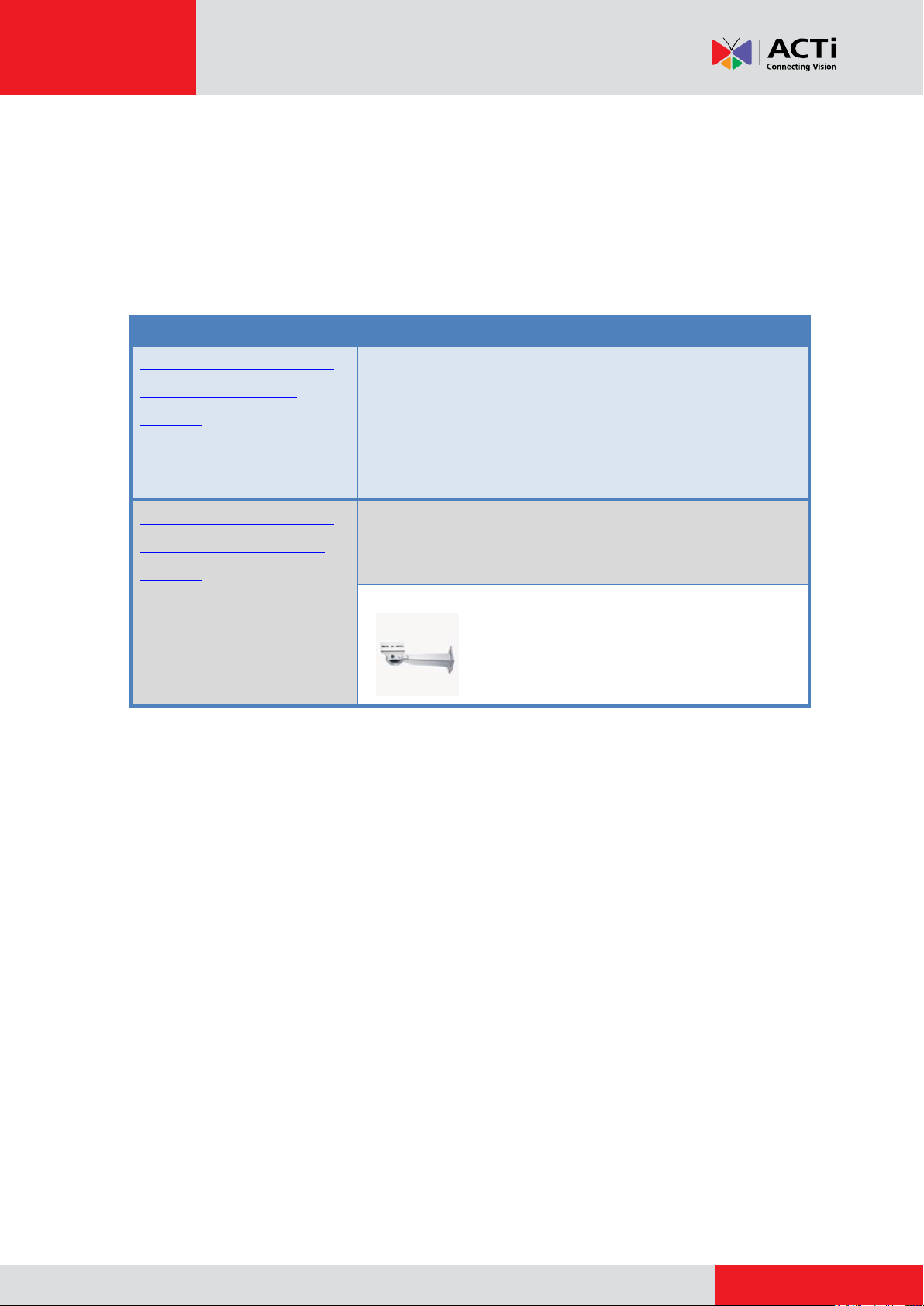
Mounting Solution
Required Accessories
Installation Procedures
Using the Bundled
Bracket
Use this solution in an indoor or outdoor installation
using the bundled light bracket.
Installation Procedures
Using the Heavy Duty
Bracket
Use this solution when installing the camera outdoors
with fierce weather conditions.
PMAX-1103
Mounting Solutions
The camera comes with a removable bracket which can be used for wall installations. For areas
with fierce weather conditions and storms, the light bundled bracket can be replaced with the
heavy duty bracket (optional and purchased separately).
4
Page 5

www.acti.com
Installation Guide
Installation Procedures Using the
Bundled Bracket
The steps in installing the camera with the light bundled bracket vary depending on the preferred
waterproof cabling solution. There are 3 ways to do the cabling:
Installation Using the Bundled Bracket and Sealant Tape, see page 6.
Installation Using the Bundled Bracket and Flex Conduit (Not applicable for D3x
Series), see page 9.
Installation Using the Bundled Bracket and Naked Cable (Not applicable for D3x
Series), see page 16.
5
Page 6
www.acti.com
Installation Guide
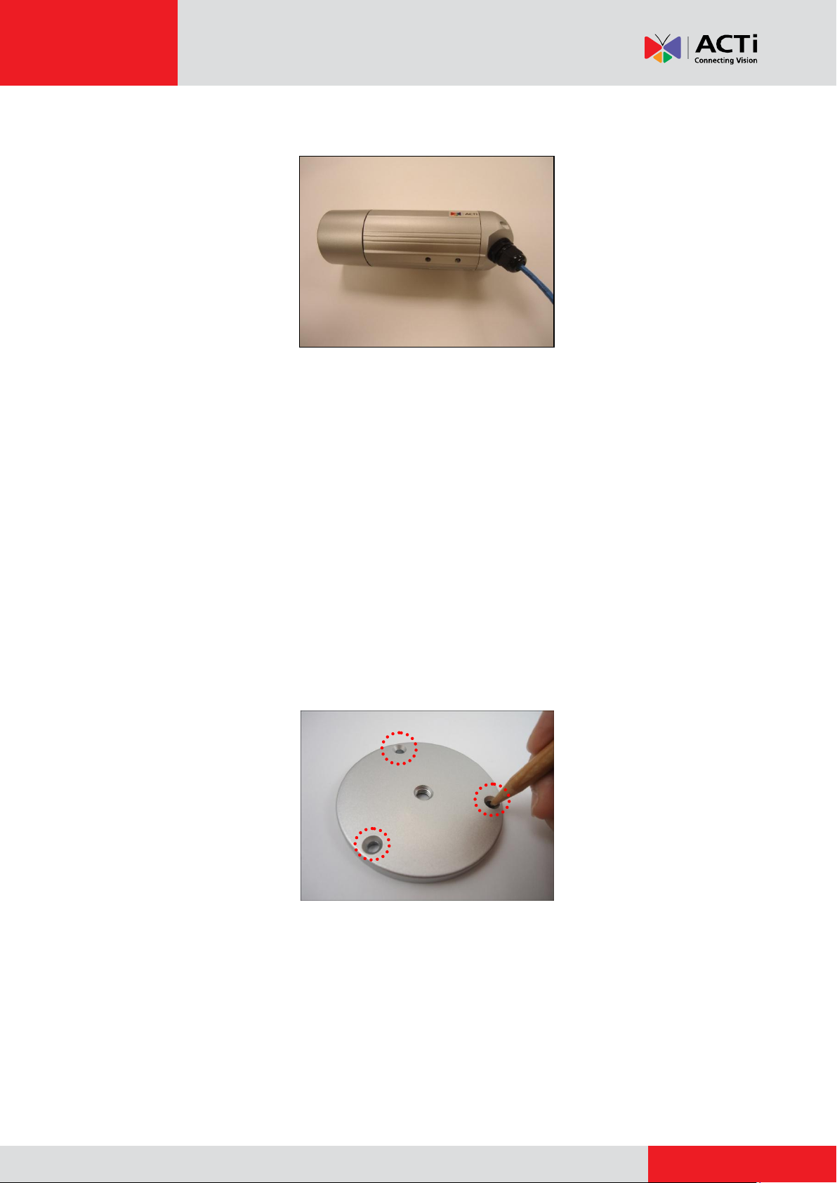
Installation Using the Bundled Bracket and Sealant Tape
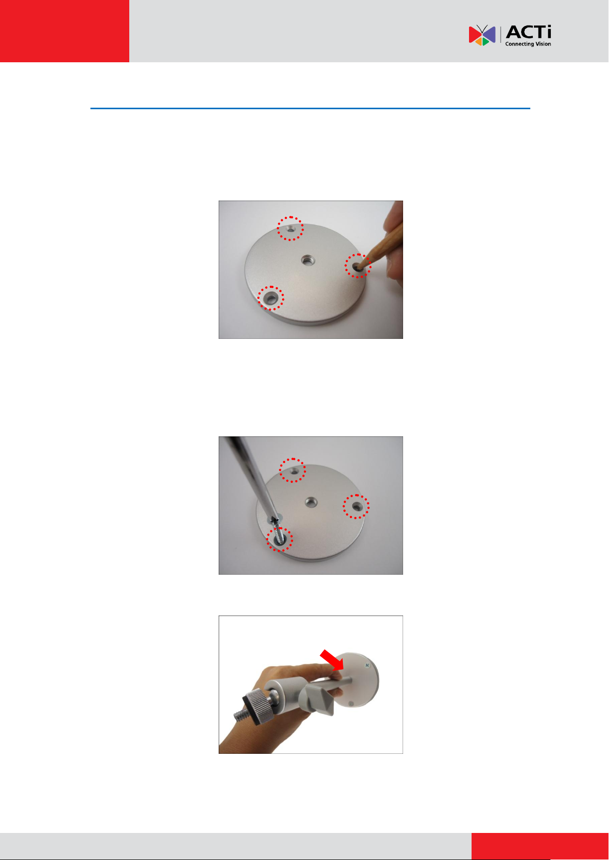
Step 1: Install the Bracket
1. Mark the location of the three (3) screw holes using the bracket plate included in the
package.
NOTE: Depending on the surface where you will install the camera, it may be necessary to
drill the holes and use the supplied screw plugs.
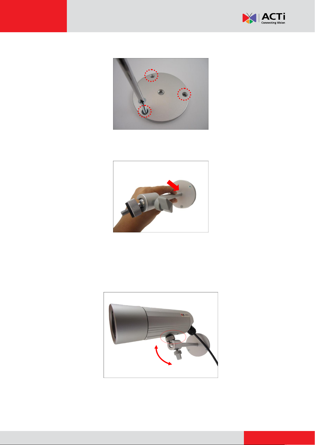
2. Attach the plate to the surface using the three (3) supplied screws.
3. Attach the bracket to the plate.
6
Page 7
www.acti.com
Installation Guide
Camera Side
Network Side
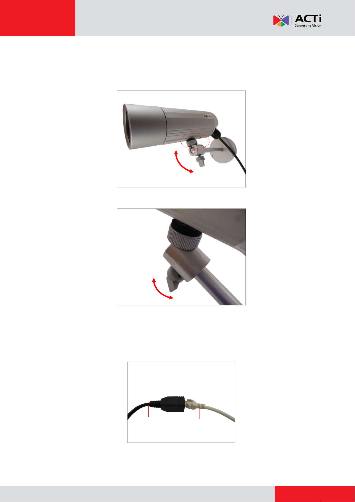
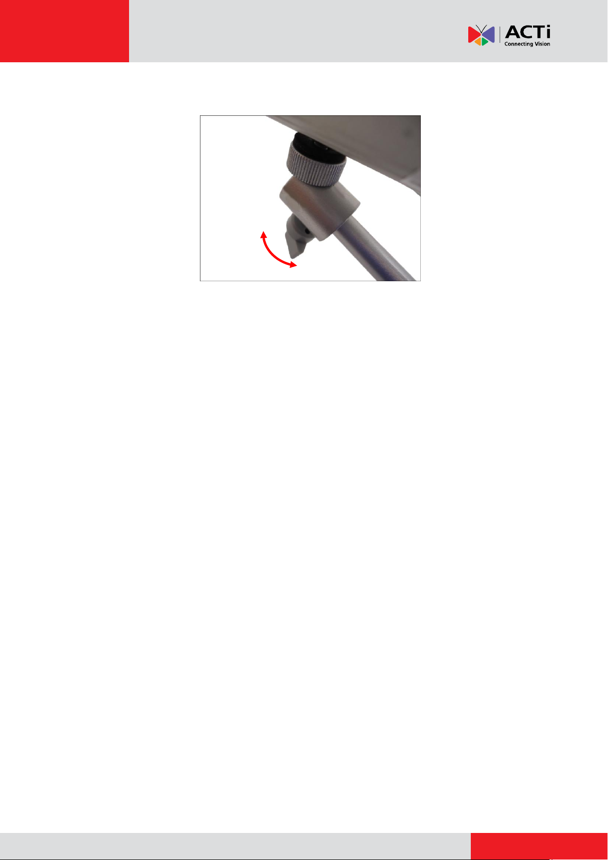
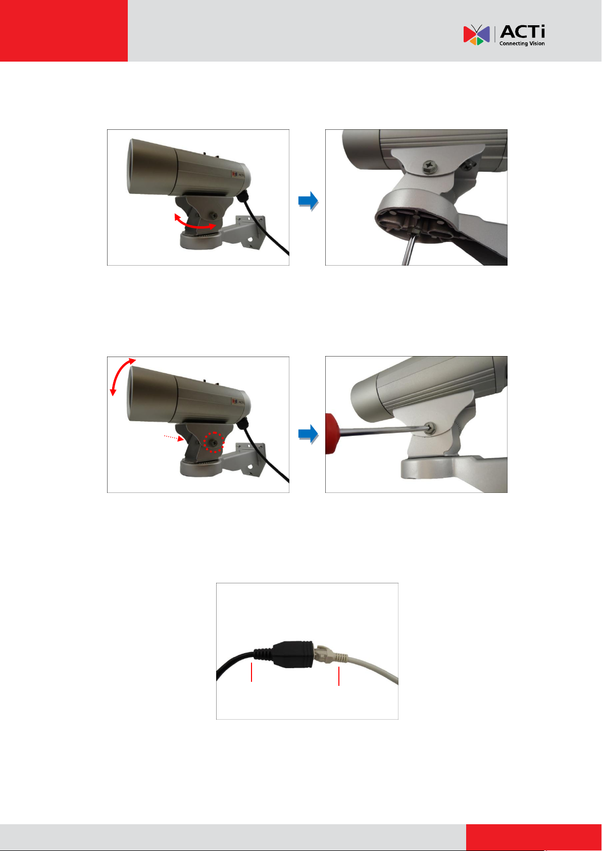
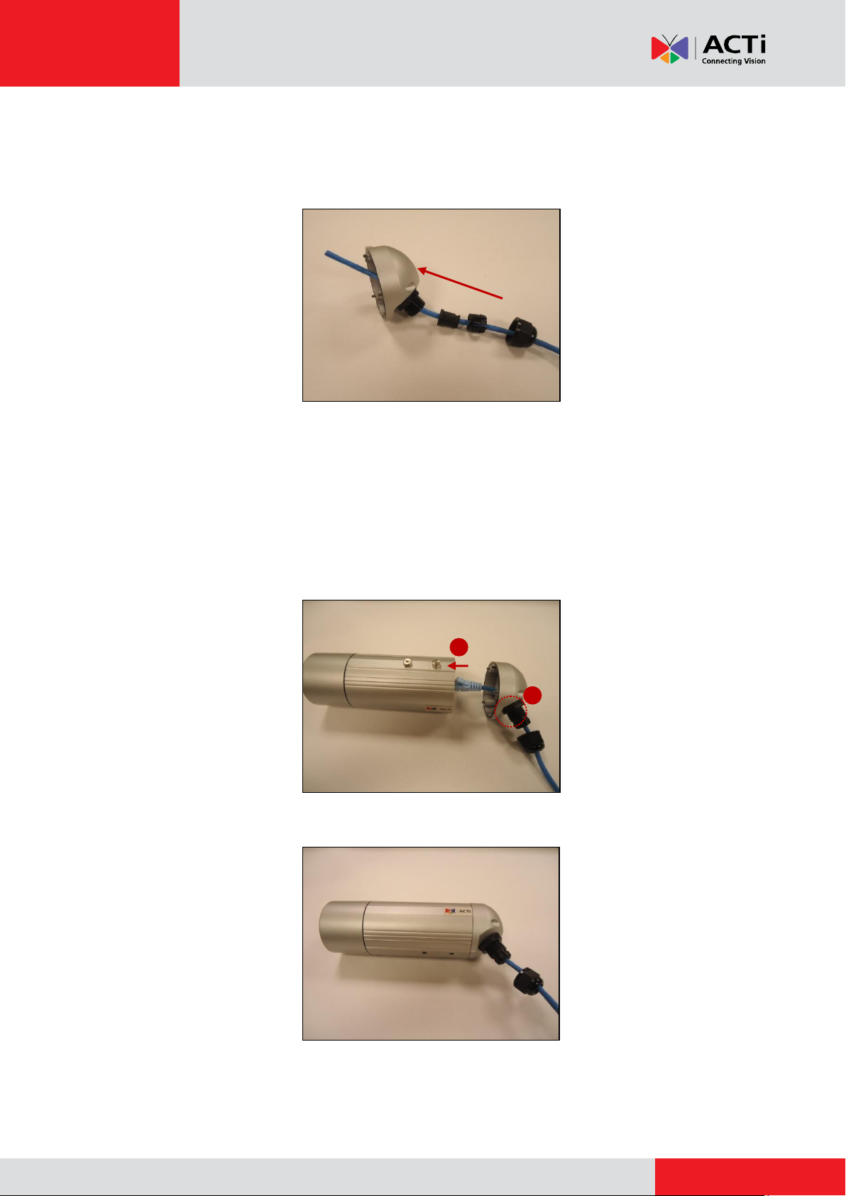
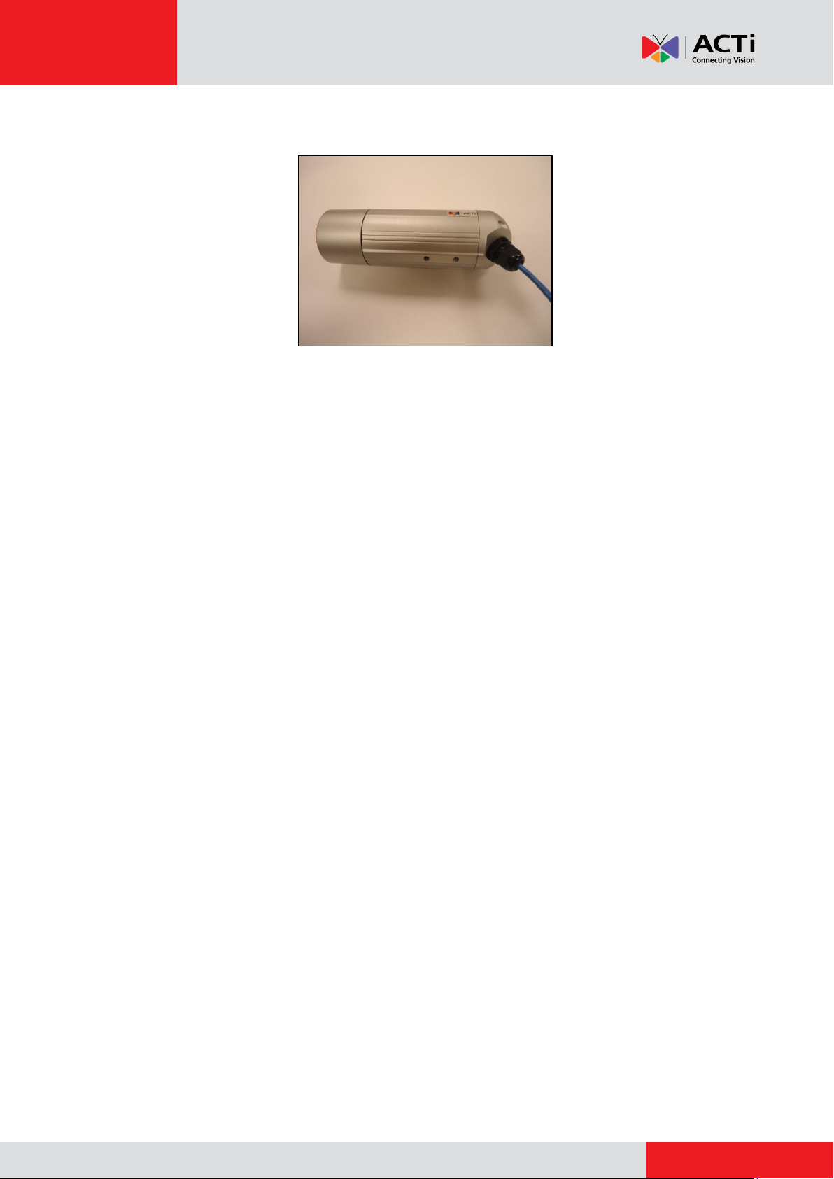
Step 2: Install the Camera
1. Depending on how you want to install the camera, attach the camera to the bracket through
one of the two (2) holes below or to the hole on the back cover (only in D3x series).
2. Adjust the camera viewing angle and tighten the knob to fix the camera position.
Step 3: Connect the Cables
1. Connect the Ethernet cable from the network side to the Ethernet port of the camera to
complete the installation.
NOTES on using Ethernet cables: For outdoor installations, it is recommended to use
exterior-grade Ethernet cables (CAT5/CAT5e/CAT6); ordinary Ethernet cables are only
7
Page 8
www.acti.com
Installation Guide
designed for indoor use and may deteriorate quickly when exposed to outdoor elements.
Exterior-grade Ethernet cables are waterproof and do not require a conduit.
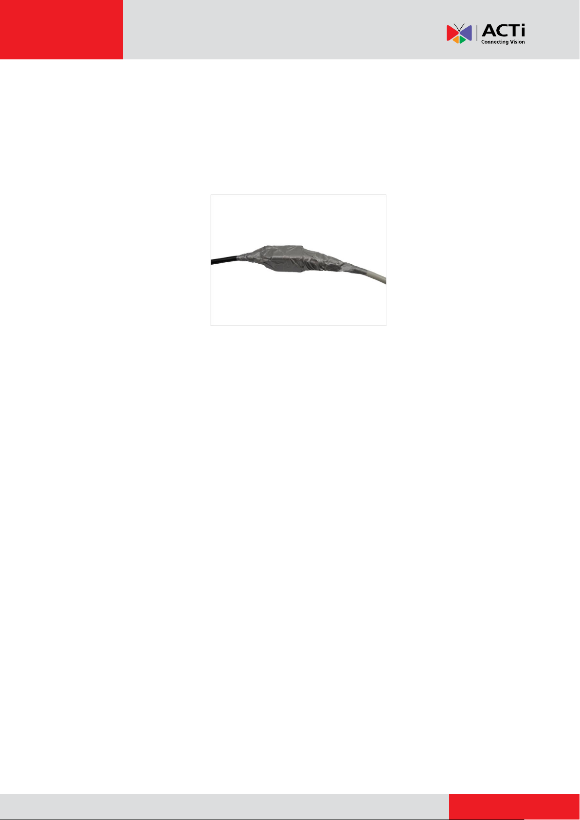
2. If the camera will be installed outdoors, waterproof the cable connection by wrapping it using
a moisture-sealant tape, such as 3M PRODUCTS Core Series 4-1000 (not included in the
package) or equivalent. See example below.
Step 4: Access the Camera Live View
See How to Access the Camera Live View on page 42 for more information.
Step 5: Adjust the Viewing Angle and Focus
Based on the Live View, adjust the viewing angle and focus of the camera. Adjustments vary per
model; for detailed information, please refer to the following sections:
For D3x / E3x camera series, see D3x / E3x Series on page 50.
For D4x / E41 / E41A / E42 / E42A / E43 / E43A series, see D4x / E41 / E41A / E42 /
E42A / E43 / E43A Series on page 52.
Step 6: Attach the Sunshield
See How to Attach the Sunshield on page 53 for more information.
8
Page 9
www.acti.com
Installation Guide
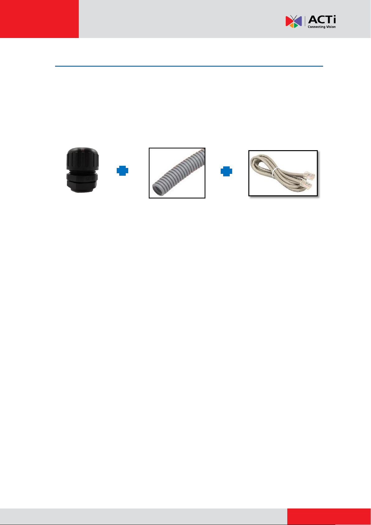
Installation Using the Bundled Bracket and Flex Conduit
The D4x, E3x, E41, E41A, E42, E42A, E43, E43A camera series come with a bundled conduit
gland. Use the conduit gland with a 1/2"-size flex conduit (not included in the package) to protect
the Ethernet cable against fierce weather conditions. To use conduit with the camera, the
pre-installed network cable with "pigtail" (female connector) must be replaced with a standard
Ethernet cable.
NOTE: The flex conduit and Ethernet cable are not included in the package and must be sold
separately. When purchasing, make sure the flex conduit size is 1/2" to match the bundled
conduit gland.
To do the waterproof cable installation, also prepare the following tools:
Screwdriver
Pliers
9
Page 10
www.acti.com
Installation Guide
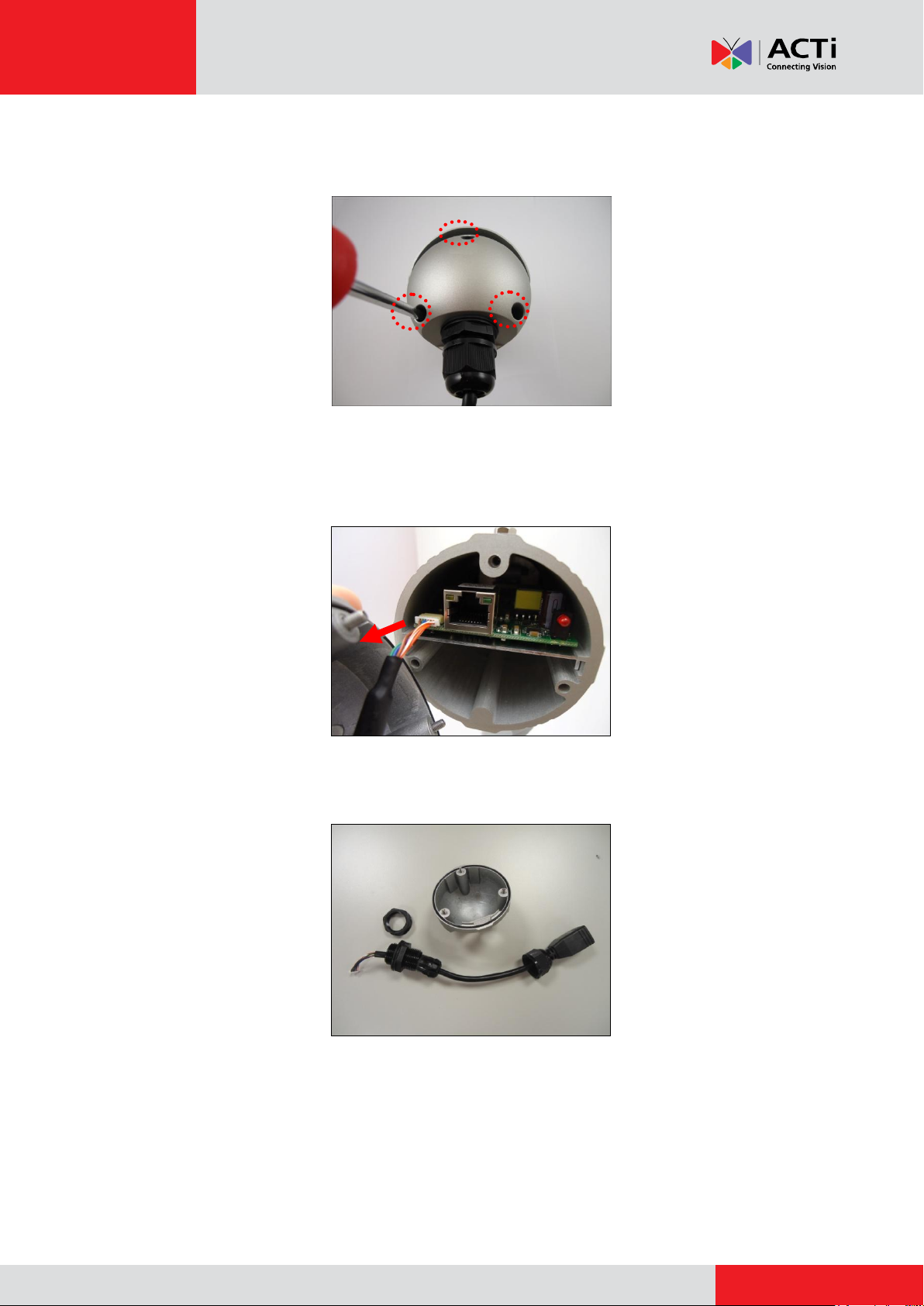
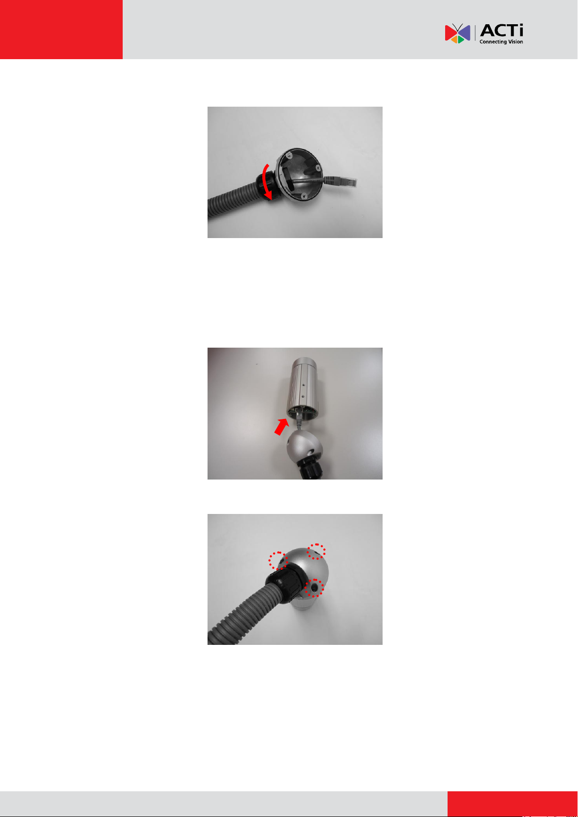
Step 1: Remove the Pre-installed Network Cable (“Pigtail”)
1. Loosen the three (3) screws to detach the back cover.
NOTE: A cable is connected inside the camera; do not abruptly pull the back cover.
2. Disconnect the network connector.
3. Remove the pre-installed cable gland and network cable using pliers (not included in the
package).
10
Page 11
www.acti.com
Installation Guide
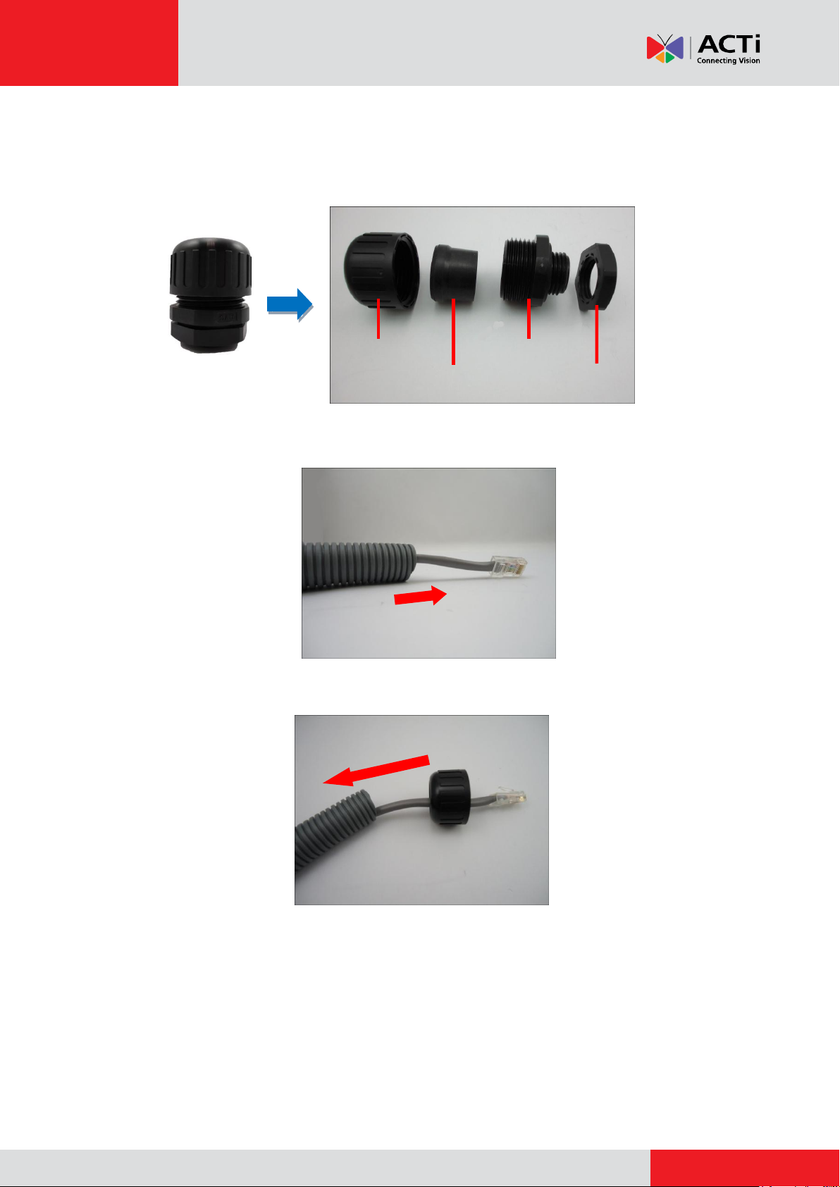
Clamping Nut
Sealing Insert
Lock Nut
Body
Step 2: Prepare the Conduit Gland and Flex Conduit
1. Disassemble the bundled conduit gland as shown below.
2. Pull the Ethernet cable through the flex conduit.
3. Insert the clamping nut through the flex conduit.
11
Page 12
www.acti.com
Installation Guide
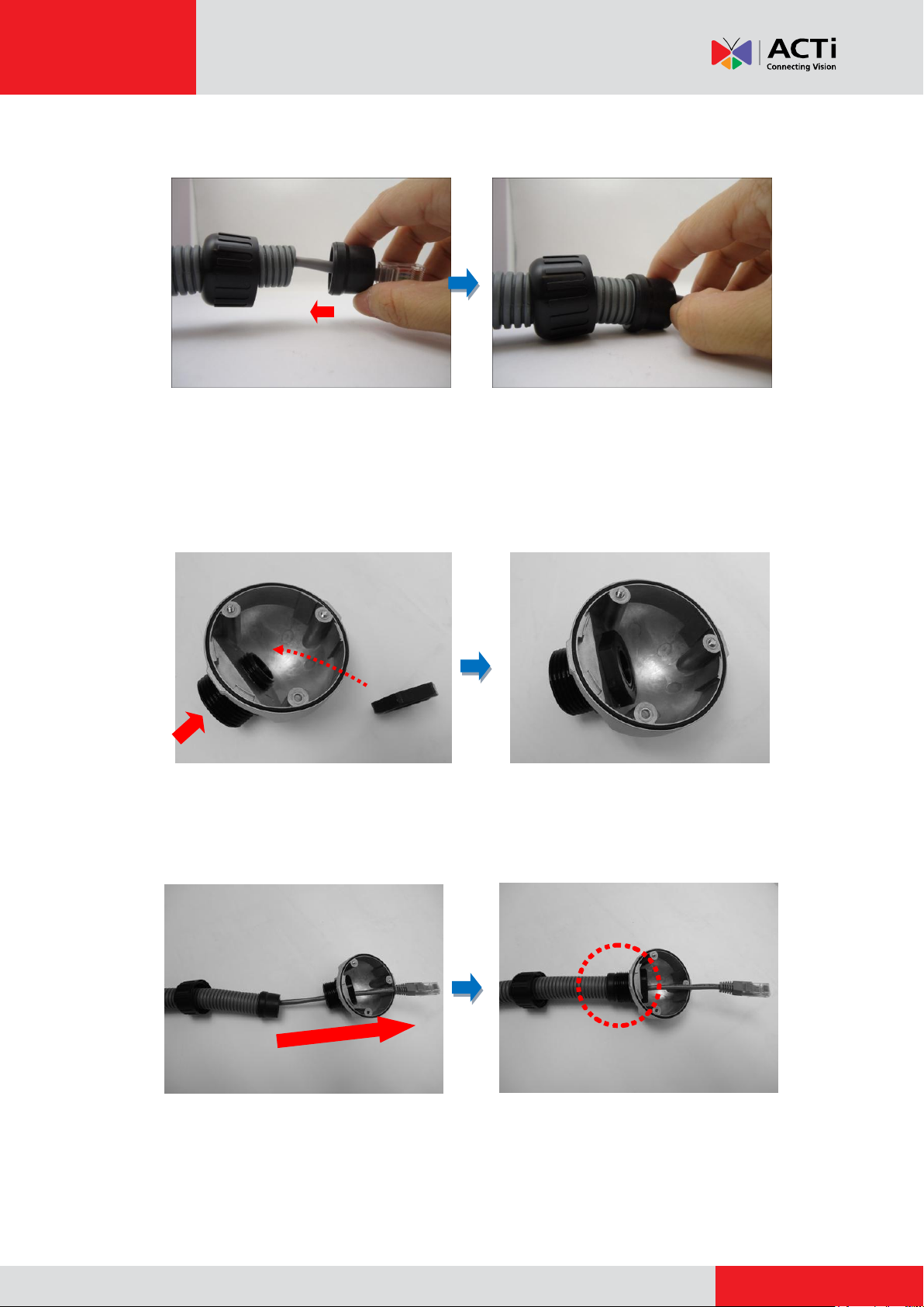
(A)
(B)
4. Insert the sealing insert and attach it at the end of the flex conduit.
Step 3: Install the Ethernet Cable
1. Insert the body (A) to the back cover and secure it with the lock nut (B).
2. Insert the Ethernet cable through the back cover and then align the sealing insert to the gland
body.
12
Page 13
www.acti.com
Installation Guide
3. Secure the clamping nut to the body.
Step 4: Connect the Ethernet Cable
1. Connect the Ethernet cable to the Ethernet port inside the camera.
2. When done, close the back cover by tightening the three (3) screws.
13
Page 14
www.acti.com
Installation Guide
Step 5: Install the Bracket
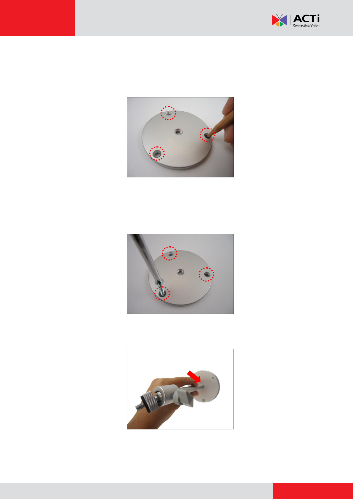
1. Mark the location of the three (3) screw holes using the bracket plate included in the
package.
NOTE: Depending on the surface where you will install the camera, it may be necessary to
drill the holes and use the supplied screw plugs.
2. Attach the plate to the surface using the three (3) supplied screws.
3. Attach the bracket to the plate.
14
Page 15
www.acti.com
Installation Guide
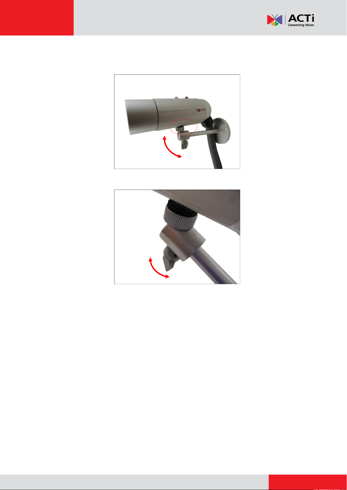
Step 6: Install the Camera
1. Attach the camera to the bracket through one of the 2 holes on the top of the camera.
2. Adjust the camera viewing angle and tighten the knob to fix the camera position.
Step 7: Connect the Camera to the Network
Connect the other end of the Ethernet cable to a PoE switch.
Step 8: Access the Camera Live View
See How to Access the Camera Live View on page 42 for more information.
Step 9: Adjust the Viewing Angle and Focus
Based on the Live View, adjust the viewing angle and focus of the camera. Adjustments vary per
model; for detailed information, please refer to the following sections:
For D3x / E3x camera series, see D3x / E3x Series on page 50.
For D4x / E41 / E41A / E42 / E42A / E43 / E43A series, see D4x / E41 / E41A / E42 /
E42A / E43 / E43A Series on page 52.
Step 10: Attach the Sunshield
See How to Attach the Sunshield on page 53 for more information.
15
Page 16

www.acti.com
Installation Guide
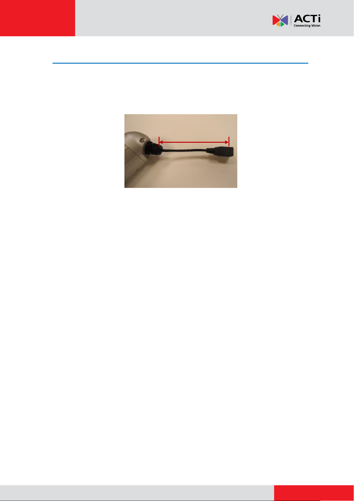
14 cm ~ 35 cm
Installation Using the Bundled Bracket and Naked Cable
The pre-installed network cable comes with an Ethernet port (female connector), or known as a
“pigtail”. The length of the cable is around 14 ~ 35 cm (varies by model). The network cable and
gland are resistant to salt water, weak acid, alcohol, oil, grease and common solvents.
In case the installation environment requires a change of this network cable, such as the use of
an Ethernet cable with male connector, it is recommended to use exterior-grade Ethernet cables
(CAT5/CAT5e/CAT6); ordinary Ethernet cables are only designed for indoor use and may
deteriorate quickly when exposed to outdoor elements. Exterior-grade Ethernet cables are
waterproof and do not require a conduit.
To replace the pre-installed network cable, follow the step-by-step procedures in this section and
prepare the following:
Screwdriver
Ethernet cable without connectors
RJ-45 Connector (x2)
RJ45 Crimping Tool
Pliers
NOTE: The above materials/tools are not included in the package.
16
Page 17
www.acti.com
Installation Guide
Sealing Nut
Claw
Seal
(A)
(B)
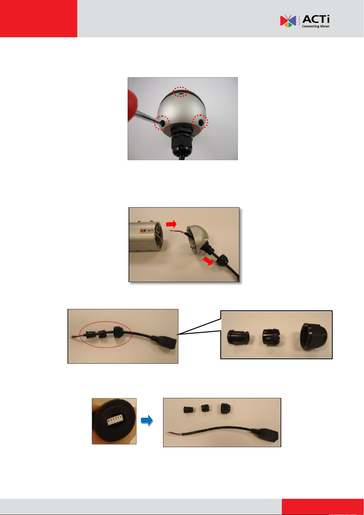
Step 1: Remove the Pre-installed Network Cable (“Pigtail”)
1. Loosen the three (3) screws to detach the back cover.
NOTE: A cable is connected inside the camera; do not abruptly pull the back cover.
2. Disconnect the network connector (A) and remove the sealing nut (B).
3. Pull out the network cable from the back cover and disassemble the parts as marked below.
4. Squeeze the seal to pull out the connector and then completely remove the seal, claw, and
sealing nut from the network cable.
17
Page 18

www.acti.com
Installation Guide
2
1
Step 2: Install the New Ethernet Cable
1. Insert the new Ethernet cable through the sealing nut, claw, seal, and cable gland of the back
cover.
2. Attach the RJ-45 connector to the Ethernet cable. See How to Make an Ethernet Cable on
page 54.
3. Assemble the seal and claw, and then connect the RJ-45 connector to the Ethernet port
inside the camera.
4. Attach the back cover by tightening the three (3) screws.
18
Page 19
www.acti.com
Installation Guide
5. Tighten the sealing nut.
NOTES on using Ethernet cables: When replacing the pre-installed network cable, it is
recommended to use exterior-grade Ethernet cables (CAT5/CAT5e/CAT6); ordinary Ethernet
cables are only designed for indoor use and may deteriorate quickly when exposed to
outdoor elements. Exterior-grade Ethernet cables are waterproof and do not require a
conduit.
Step 3: Install the Bracket
1. Mark the location of the three (3) screw holes using the bracket plate included in the
package.
NOTE: Depending on the surface where you will install the camera, it may be necessary to
drill the holes and use the supplied screw plugs.
19
Page 20
www.acti.com
Installation Guide
2. Attach the plate to the surface using the three (3) supplied screws.
3. Attach the bracket to the plate.
Step 4: Install the Camera
1. Depending on how you want to install the camera, attach the camera to the bracket through
one of the two (2) holes below or to the hole on the back cover (only in D3x series).
20
Page 21
www.acti.com
Installation Guide
2. Adjust the camera viewing angle and tighten the knob to fix the camera position.
Step 5: Connect the Camera to the Network
Connect the other end of the Ethernet cable to a PoE switch.
Step 6: Access the Camera Live View
See How to Access the Camera Live View on page 42 for more information.
Step 7: Adjust the Viewing Angle and Focus
Based on the Live View, adjust the viewing angle and focus of the camera. Adjustments vary per
model; for detailed information, please refer to the following sections:
For D3x / E3x camera series, see D3x / E3x Series on page 50.
For D4x / E41 / E41A / E42 / E42A / E43 / E43A series, see D4x / E41 / E41A / E42 /
E42A / E43 / E43A Series on page 52.
Step 8: Attach the Sunshield
See How to Attach the Sunshield on page 53 for more information.
21
Page 22

www.acti.com
Installation Guide
Installation Procedures Using the Heavy
Duty Bracket
In areas with fierce weather conditions and storms, it is recommended to use the heavy duty
bracket. The heavy duty bracket is an optional item and is sold separately. The steps in installing
the camera with the heavy duty bracket vary depending on the preferred waterproof cabling
solution. There are 3 ways to do the cabling:
Installation Using the Heavy Duty Bracket and Sealant Tape, see page 23.
Installation Using the Heavy Duty Bracket and Flex Conduit (Not applicable for
D3x Series), see page 27.
Installation Using the Bundled Bracket and Naked Cable (Not applicable for D3x
Series), see page 35.
22
Page 23
www.acti.com
Installation Guide
Installation Using the Heavy Duty Bracket and Sealant
Tape
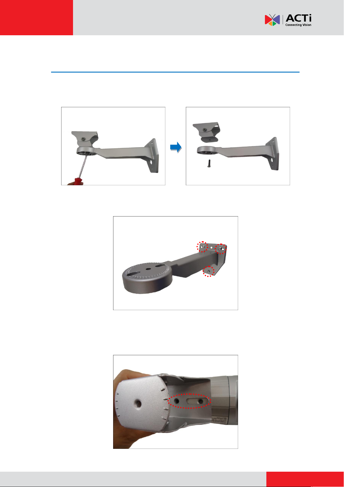
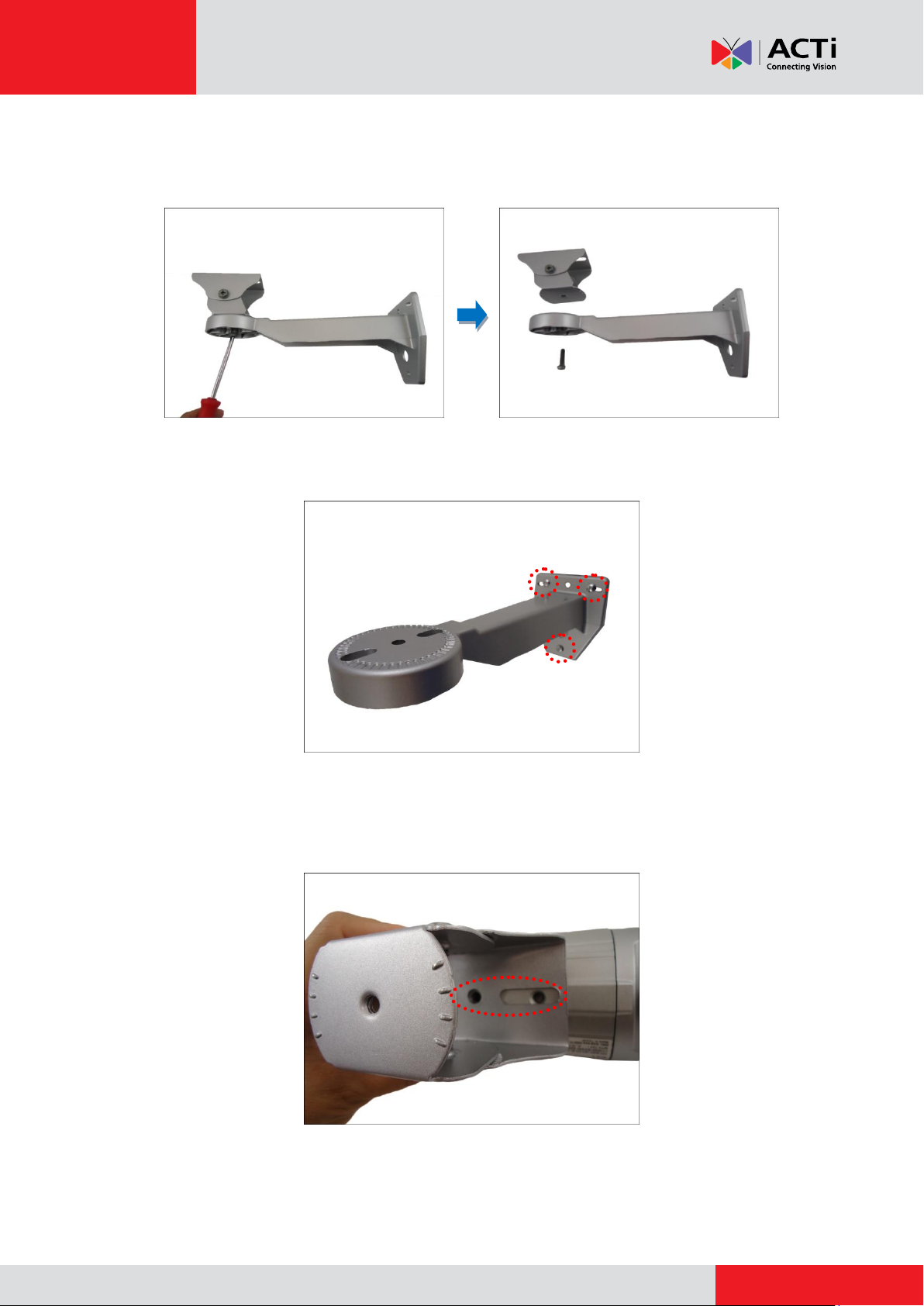
Step 1: Install the Bracket
1. Remove the screw to detach the camera holder from the bracket.
2. Mark the location of the three (3) screw holes using the bracket and attach the bracket to the
wall using the supplied screws.
NOTE: Depending on the surface where you will install the camera, it may be necessary to
drill the holes and use the supplied screw plugs.
3. Align the screw holes of the holder to the bottom screw holes of the camera.
23
Page 24

www.acti.com
Installation Guide
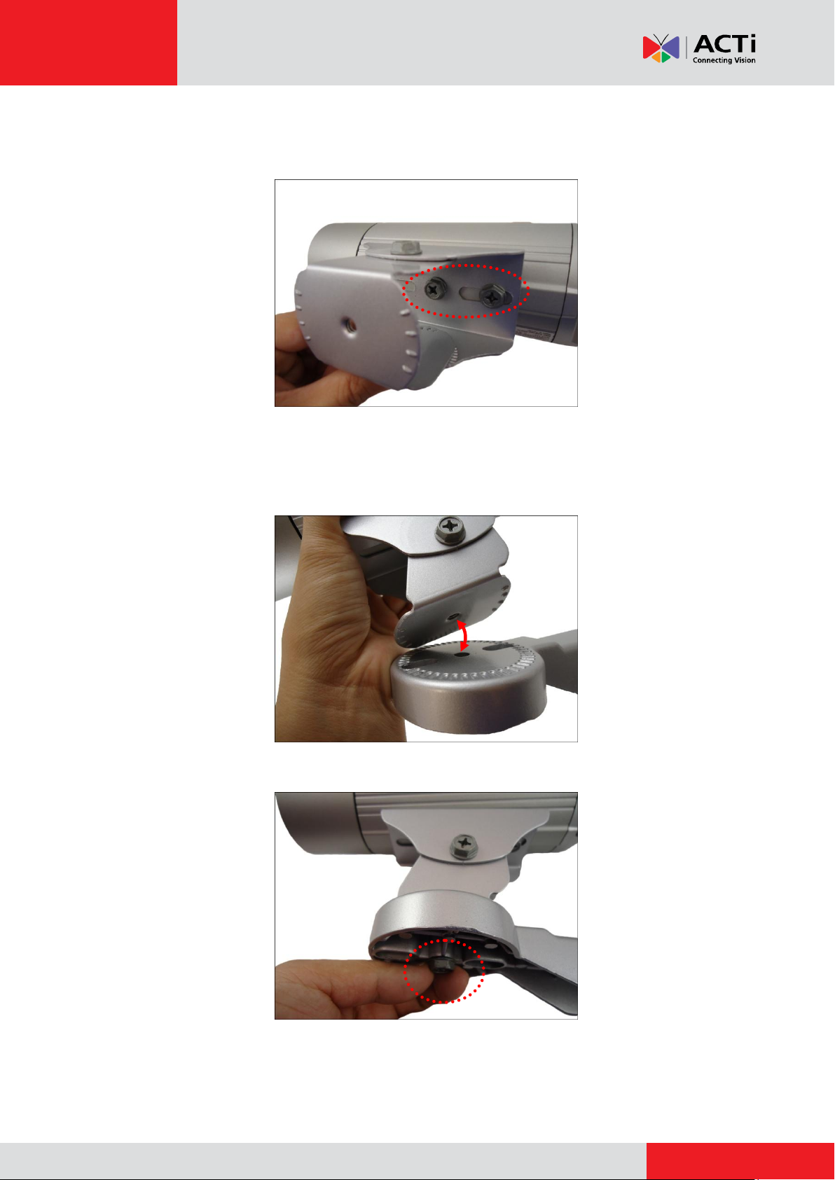
4. Attach the two (2) screws (supplied in the heavy duty bracket package) to secure the camera
to the holder.
Step 2: Install the Camera
1. Align the screw hole of the holder to the heavy duty bracket.
2. Loosely attach the screw to secure the holder to the bracket.
24
Page 25
www.acti.com
Installation Guide
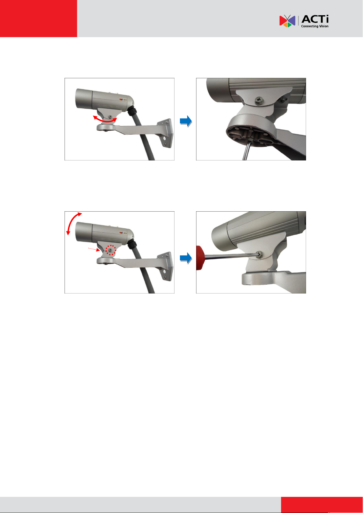
Camera Side
Network Side
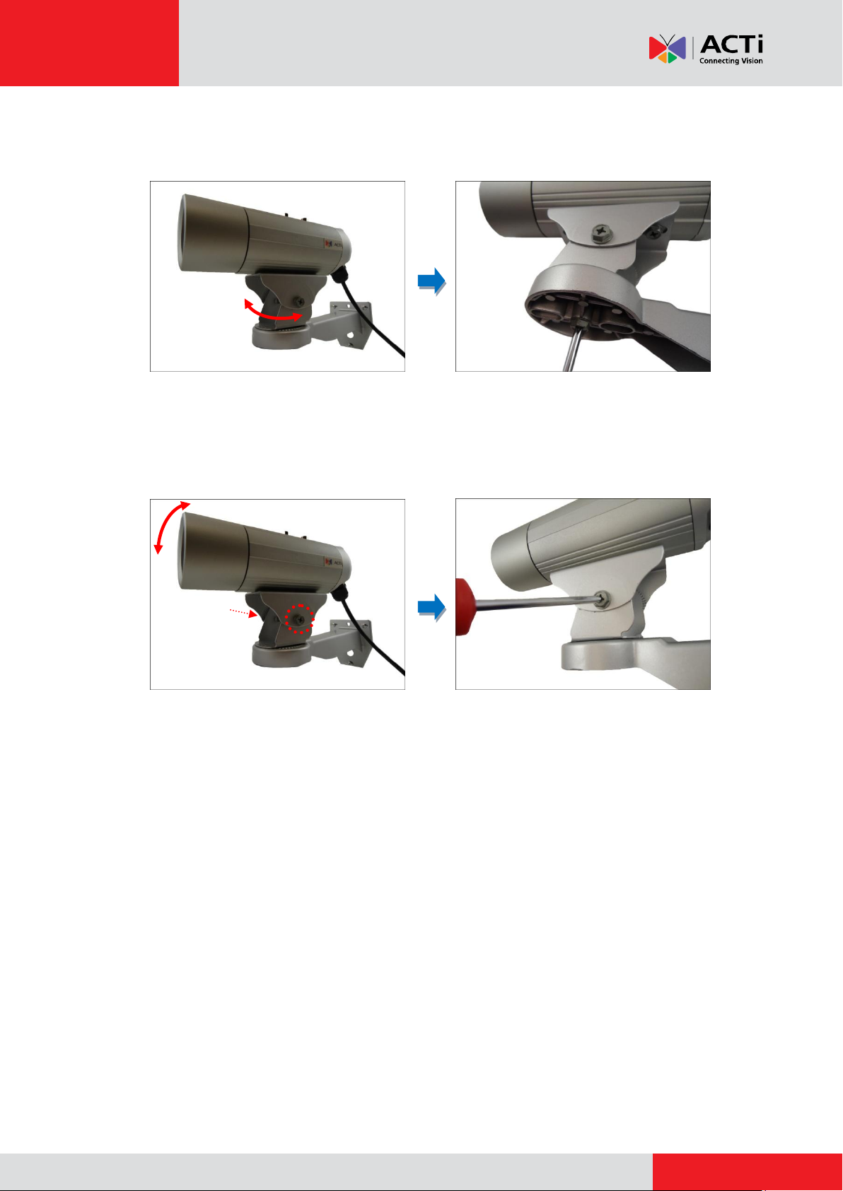
3. As needed, turn the holder left or right to adjust the camera viewing direction. Then, secure
the screw tightly to fix the position.
4. As needed, loosen the two (2) side screws of the holder and then move the camera up or
down to adjust the camera viewing angle. Then, tighten the two (2) side screws to fix the
position.
Step 3: Connect the Cables
1. Connect the Ethernet cable from the network side to the Ethernet port of the camera to
complete the installation.
NOTES on using Ethernet cables: For outdoor installations, it is recommended to use
exterior-grade Ethernet cables (CAT5/CAT5e/CAT6); ordinary Ethernet cables are only
designed for indoor use and may deteriorate quickly when exposed to outdoor elements.
Exterior-grade Ethernet cables are waterproof and do not require a conduit.
25
Page 26

www.acti.com
Installation Guide
2. If the camera will be installed outdoors, waterproof the cable connection by wrapping it using
a moisture-sealant tape, such as 3M PRODUCTS Core Series 4-1000 (not included in the
package) or equivalent. See example below.
Step 4: Access the Camera Live View
See How to Access the Camera Live View on page 42 for more information.
Step 5: Adjust the Viewing Angle and Focus
Based on the Live View, adjust the viewing angle and focus of the camera. Adjustments vary per
model; for detailed information, please refer to the following sections:
For D3x / E3x camera series, see D3x / E3x Series on page 50.
For D4x / E41 / E41A / E42 / E42A / E43 / E43A series, see D4x / E41 / E41A / E42 /
E42A / E43 / E43A Series on page 52.
Step 6: Attach the Sunshield
See How to Attach the Sunshield on page 53 for more information.
26
Page 27

www.acti.com
Installation Guide
Installation Using the Heavy Duty Bracket and Flex
Conduit
The D4x, E3x, E41, E41A, E42, E42A, E43, E43A camera series come with a bundled conduit
gland. Use the conduit gland with a 1/2"-size flex conduit (not included in the package) to protect
the Ethernet cable against fierce weather conditions. To use conduit with the camera, the
pre-installed network cable with "pigtail" (female connector) must be replaced with a standard
Ethernet cable.
NOTE: The flex conduit and Ethernet cable are not included in the package and must be sold
separately. When purchasing, make sure the flex conduit size is 1/2" to match the bundled
conduit gland.
To do the waterproof cable installation, also prepare the following tools:
Screwdriver
Pliers
27
Page 28

www.acti.com
Installation Guide
Step 1: Remove the Pre-installed Network Cable (“Pigtail”)
1. Loosen the three (3) screws to detach the back cover.
NOTE: A cable is connected inside the camera; do not abruptly pull the back cover.
2. Disconnect the network connector.
3. Remove the pre-installed cable gland and network cable using pliers (not included in the
package).
28
Page 29

www.acti.com
Installation Guide
Clamping Nut
Sealing Insert
Lock Nut
Body
Step 2: Prepare the Conduit Gland and Flex Conduit
1. Disassemble the bundled conduit gland as shown below.
2. Pull the Ethernet cable through the flex conduit.
3. Insert the clamping nut through the flex conduit.
29
Page 30

www.acti.com
Installation Guide
(A)
(B)
4. Insert the sealing insert and attach it at the end of the flex conduit.
Step 3: Install the Ethernet Cable
1. Insert the body (A) to the back cover and secure it with the lock nut (B).
2. Insert the Ethernet cable through the back cover and then align the sealing insert to the gland
body.
30
Page 31

www.acti.com
Installation Guide
3. Secure the clamping nut to the body.
Step 4: Connect the Ethernet Cable
1. Connect the Ethernet cable to the Ethernet port inside the camera.
2. When done, close the back cover by tightening the three (3) screws.
31
Page 32
www.acti.com
Installation Guide
Step 5: Install the Bracket
1. Remove the screw to detach the camera holder from the bracket.
2. Mark the location of the three (3) screw holes using the bracket and attach the bracket to the
wall using the supplied screws.
NOTE: Depending on the surface where you will install the camera, it may be necessary to
drill the holes and use the supplied screw plugs.
3. Align the screw holes of the holder to the bottom screw holes of the camera.
32
Page 33
www.acti.com
Installation Guide
4. Attach the two (2) screws (supplied in the heavy duty bracket package) to secure the camera
to the holder.
Step 6: Install the Camera
1. Align the screw hole of the holder to the heavy duty bracket.
2. Loosely attach the screw to secure the holder to the bracket.
33
Page 34
www.acti.com
Installation Guide
3. As needed, turn the holder left or right to adjust the camera viewing direction. Then, secure
the screw tightly to fix the position.
4. As needed, loosen the two (2) side screws of the holder and then move the camera up or
down to adjust the camera viewing angle. Then, tighten the two (2) side screws to fix the
position.
Step 7: Connect the Camera to the Network
Connect the other end of the Ethernet cable to a PoE switch.
Step 8: Access the Camera Live View
See How to Access the Camera Live View on page 42 for more information.
Step 9: Adjust the Viewing Angle and Focus
Based on the Live View, adjust the viewing angle and focus of the camera. Adjustments vary per
model; for detailed information, please refer to the following sections:
For D3x / E3x camera series, see D3x / E3x Series on page 50.
For D4x / E41 / E41A / E42 / E42A / E43 / E43A series, see D4x / E41 / E41A / E42 /
E42A / E43 / E43A Series on page 52.
Step 10: Attach the Sunshield
See How to Attach the Sunshield on page 53 for more information.
34
Page 35
www.acti.com
Installation Guide
14 cm ~ 35 cm
Installation Using the Bundled Bracket and Naked Cable
The pre-installed network cable comes with an Ethernet port (female connector), or known as a
“pigtail”. The length of the cable is around 14 ~ 35 cm (varies by model). The network cable and
gland are resistant to salt water, weak acid, alcohol, oil, grease and common solvents.
In case the installation environment requires a change of this network cable, such as the use of
an Ethernet cable with male connector, it is recommended to use exterior-grade Ethernet cables
(CAT5/CAT5e/CAT6); ordinary Ethernet cables are only designed for indoor use and may
deteriorate quickly when exposed to outdoor elements. Exterior-grade Ethernet cables are
waterproof and do not require a conduit.
To replace the pre-installed network cable, follow the step-by-step procedures in this section and
prepare the following:
Screwdriver
Ethernet cable without connectors
RJ-45 Connector (x2)
RJ45 Crimping Tool
Pliers
NOTE: The above materials/tools are not included in the package.
35
Page 36

www.acti.com
Installation Guide
Sealing Nut
Claw
Seal
(A)
(B)
Step 1: Remove the Pre-installed Network Cable (“Pigtail”)
1. Loosen the three (3) screws to detach the back cover.
NOTE: A cable is connected inside the camera; do not abruptly pull the back cover.
2. Disconnect the network connector (A) and remove the sealing nut (B).
3. Pull out the network cable from the back cover and disassemble the parts as marked below.
4. Squeeze the seal to pull out the connector and then completely remove the seal, claw, and
sealing nut from the network cable.
36
Page 37
www.acti.com
Installation Guide
2
1
Step 2: Install the New Ethernet Cable
1. Insert the new Ethernet cable through the sealing nut, claw, seal, and cable gland of the back
cover.
2. Attach the RJ-45 connector to the Ethernet cable. See How to Make an Ethernet Cable on
page 54.
3. Assemble the seal and claw, and then connect the RJ-45 connector to the Ethernet port
inside the camera.
4. Attach the back cover by tightening the three (3) screws.
37
Page 38
www.acti.com
Installation Guide
5. Tighten the sealing nut.
NOTES on using Ethernet cables: When replacing the pre-installed network cable, it is
recommended to use exterior-grade Ethernet cables (CAT5/CAT5e/CAT6); ordinary Ethernet
cables are only designed for indoor use and may deteriorate quickly when exposed to
outdoor elements. Exterior-grade Ethernet cables are waterproof and do not require a
conduit.
38
Page 39

www.acti.com
Installation Guide
Step 3: Install the Bracket
1. Remove the screw to detach the camera holder from the bracket.
2. Mark the location of the three (3) screw holes using the bracket and attach the bracket to the
wall using the supplied screws.
NOTE: Depending on the surface where you will install the camera, it may be necessary to
drill the holes and use the supplied screw plugs.
3. Align the screw holes of the holder to the bottom screw holes of the camera.
39
Page 40

www.acti.com
Installation Guide
4. Attach the two (2) screws (supplied in the heavy duty bracket package) to secure the camera
to the holder.
Step 4: Install the Camera
1. Align the screw hole of the holder to the heavy duty bracket.
2. Loosely attach the screw to secure the holder to the bracket.
40
Page 41
www.acti.com
Installation Guide
3. As needed, turn the holder left or right to adjust the camera viewing direction. Then, secure
the screw tightly to fix the position.
4. As needed, loosen the two (2) side screws of the holder and then move the camera up or
down to adjust the camera viewing angle. Then, tighten the two (2) side screws to fix the
position.
Step 5: Connect the Camera to the Network
Connect the other end of the Ethernet cable to a PoE switch.
Step 6: Access the Camera Live View
See How to Access the Camera Live View on page 42 for more information.
Step 7: Adjust the Viewing Angle and Focus
Based on the Live View, adjust the viewing angle and focus of the camera. Adjustments vary per
model; for detailed information, please refer to the following sections:
For D3x / E3x camera series, see D3x / E3x Series on page 50.
For D4x / E41 / E41A / E42 / E42A / E43 / E43A series, see D4x / E41 / E41A / E42 /
E42A / E43 / E43A Series on page 52.
Step 8: Attach the Sunshield
See How to Attach the Sunshield on page 53 for more information.
41
Page 42

www.acti.com
Installation Guide
Appendices
How to Access the Camera Live View
Connect the Equipment
To be able to connect to the camera firmware from your PC, both the camera and the PC have to
be connected to each other via Ethernet cable. At the same time, the camera has to have its own
power supply. In case of PoE cameras, you can use a PoE Injector or a PoE Switch between the
camera and the PC. The cameras that have the DC power connectors may be powered on by
using a power adaptor.
Configure the IP Addresses
In order to be able to communicate with the camera from your PC, both the camera and the PC
have to be within the same network segment. In most cases, it means that they both should have
very similar IP addresses, where only the last number of the IP address is different from each
other. There are 2 different approaches to IP Address management in Local Area Networks – by
DHCP Server or Manually.
Using DHCP server to assign IP addresses:
If you have connected the computer and the camera into the network that has a DHCP server
running, then you do not need to configure the IP addresses at all – both the camera and the PC
would request a unique IP address from DHCP server automatically. In such case, the camera
will immediately be ready for the access from the PC. The user, however, might not know the IP
address of the camera yet. It is necessary to know the IP address of the camera in other to be
able to access it by using a Web browser.
42
Page 43

www.acti.com
Installation Guide
The quickest way to discover the cameras in the network is to use the simplest network
search, built in the Windows system – just by pressing the “Network” icon, all the cameras of the
local area network will be discovered by Windows thanks to the UPnP function support of our
cameras.
In the example below, we successfully found the camera model that we had just connected to the
network.
By double-clicking the mouse on the camera model it is possible to automatically launch the
default browser of the PC with the IP address of the target camera filled in the address bar of the
browser already.
43
Page 44

www.acti.com
Installation Guide
If you work with our cameras regularly, then there is even a better way to discover the
cameras in the network – by using IP Utility. The IP Utility is a light software tool that can not
only discover the cameras, but also list lots of valuable information, such as IP and MAC
addresses, serial numbers, firmware versions, etc, and allows quick configuration of multiple
devices at the same time.
The IP Utility can be downloaded for free from http://www.acti.com/IP_Utility
With just one click, you can launch the IP Utility and there will be an instant report as follows:
You can quickly notice the camera model in the list. Click on the IP address to automatically
launch the default browser of the PC with the IP address of the target camera filled in the address
bar of the browser already.
44
Page 45

www.acti.com
Installation Guide
1 2 3
4
Use the default camera IP address:
If there is no DHCP server in the given network, the user may have to assign the IP addresses to
both PC and camera manually to make sure they are in the same network segment.
When the camera is plugged into network and it does not detect any DHCP services, it will
automatically assign itself a default IP:
192.168.0.100
Whereas the default port number would be 80. In order to access that camera, the IP address of
the PC has to be configured to match the network segment of the camera.
Manually adjust the IP address of the PC:
In the following example, based on Windows 7, we will configure the IP address to 192.168.0.99
and set Subnet Mask to 255.255.255.0 by using the steps below:
45
Page 46

www.acti.com
Installation Guide
Manually adjust the IP addresses of multiple cameras:
If there are more than 1 camera to be used in the same local area network and there is no DHCP
server to assign unique IP addresses to each of them, all of the cameras would then have the
initial IP address of 192.168.0.100, which is not a proper situation for network devices – all the IP
addresses have to be different from each other. The easiest way to assign cameras the IP
addresses is by using IP Utility:
With the procedure shown above, all the cameras will have unique IP addresses, starting from
192.168.0.101. In case there are 20 cameras selected, the last one of the cameras would have
the IP 192.168.0.120.
Later, by pressing the “Refresh” button of the IP Utility, you will be able to see the list of cameras
with their new IP addresses.
Please note that it is also possible to change the IP addresses manually by using the Web
browser. In such case, please plug in only one camera at a time, and change its IP address by
using the Web browser before plugging in the next one. This way, the Web browser will not be
confused about two devices having the same IP address at the same time.
46
Page 47

www.acti.com
Installation Guide
Functionality
Internet Explorer
Other browsers
Live Video
Yes
Yes*
Live Video Area Resizable
Yes
No
PTZ Control
Yes
Yes
Capture the snapshot
Yes
Yes
Video overlay based configuration (Motion
Detection regions, Privacy Mask regions)
Yes
No
All the other configurations
Yes
Yes
Firwmware Version
Required Plug-In
A1D-500-V6.04.xx-AC or older
Basic VLC Media Player (http://www.videolan.org)
A1D-500-V6.05.xx-AC or newer
QuickTime (http://www.apple.com/quicktime/download/)
Access the Camera
Now that the camera and the PC are both having their unique IP addresses and are under the
same network segment, it is possible to use the Web browser of the PC to access the camera.
You can use any of the browsers to access the camera, however, the full functionality is
provided only for Microsoft Internet Explorer.
The browser functionality comparison:
* When using non-Internet Explorer browsers, free third-party software plug-ins must be installed
to the PC first to be able to get the live video feed from the camera. Check the firmware version of
the camera to determine which plug-in is necessary:
The camera firmware version can be found on the FW Version column of the IP utility or access
the Setup page of the Web Configurator (see page 49).
Disclaimer Notice: The camera manufacturer does not guarantee the compatibility of its cameras
with VLC player or QuickTime – since these are third party softwares. The third parties have the
right to modify their utility any time which might affect the compatibility. In such cases, please use
Internet Explorer browser instead.
When using Internet Explorer browser, the ActiveX control for video stream management will be
downloaded from the camera directly – the user just has to accept the use of such control when
prompted so. No other third party utilities are required to be installed in such case.
47
Page 48
www.acti.com
Installation Guide
The following examples in this manual are based on Internet Explorer browser in order to
cover all functions of the camera.
Assuming that the camera’s IP address is 192.168.0.100, you can access it by opening the Web
browser and typing the following address into Web browser’s address bar:
http://192.168.0.100
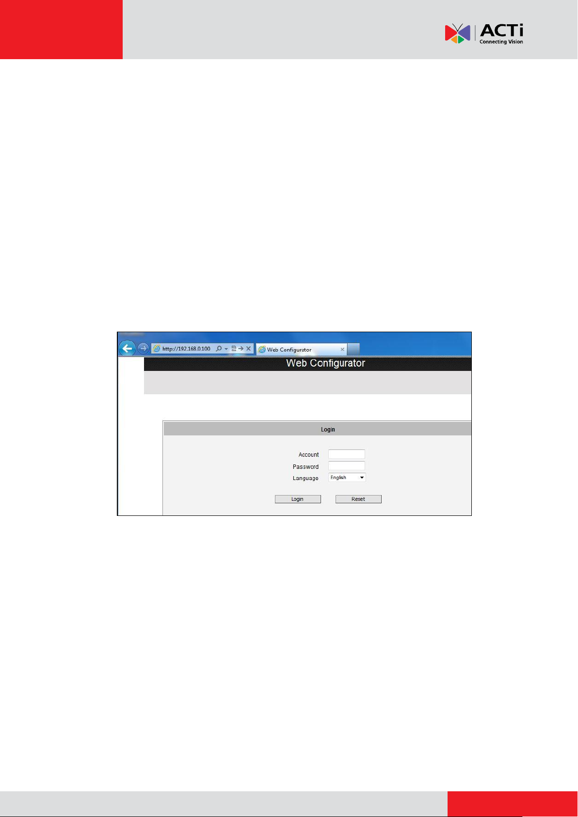
Upon successful connection to the camera, the user interface called Web Configurator would
appear together with the login page. The HTTP port number was not added behind the IP
address since the default HTTP port of the camera is 80, which can be omitted from the address
for convenience.
Before logging in, you need to know the factory default Account and Password of the camera.
Account: Admin
Password: 123456
48
Page 49
www.acti.com
Installation Guide
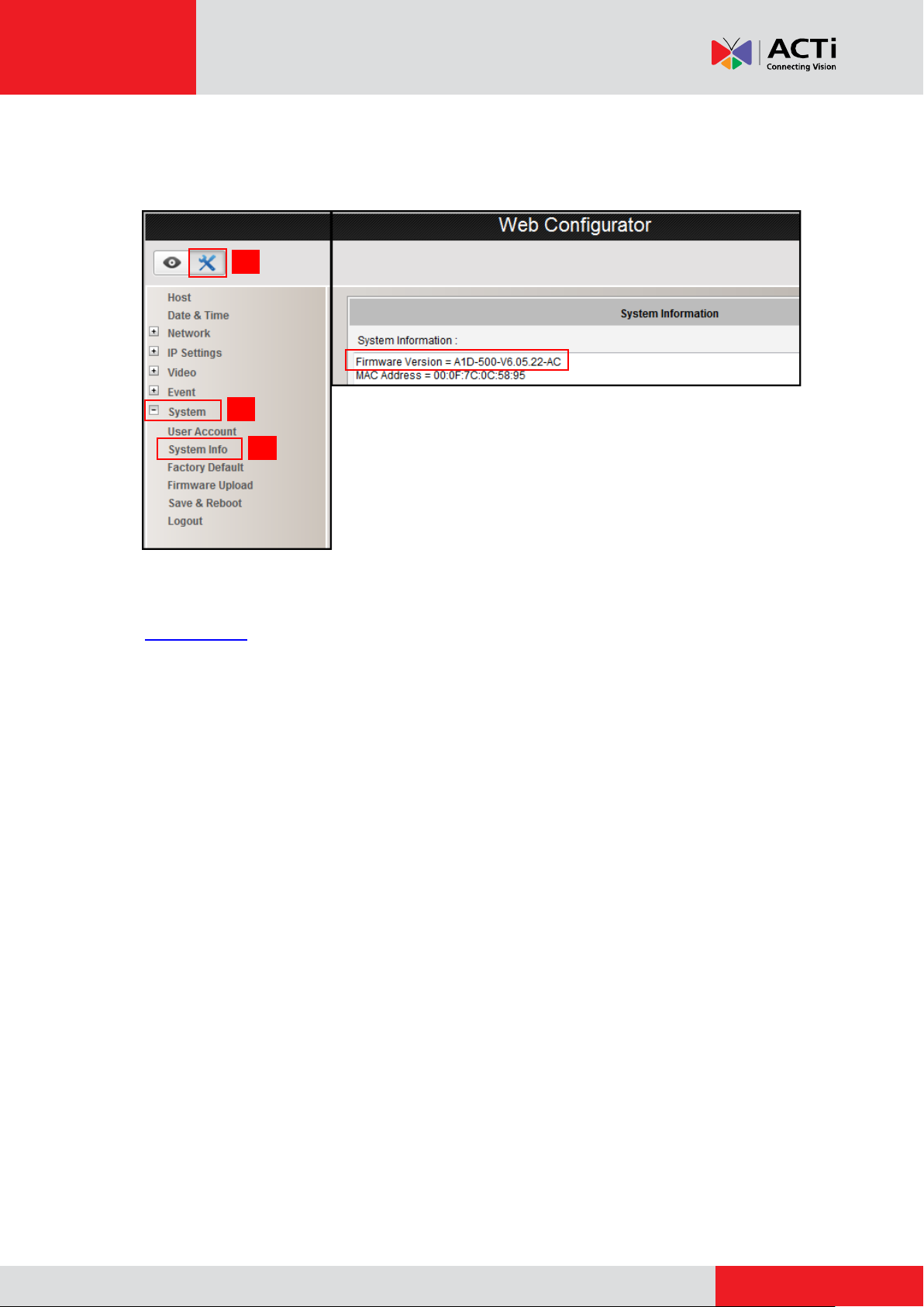
1 2 3
To check the firmware version through the Web Configurator, access the Setup page and click
System > System Info.
For further operations, please refer to the Firmware User Manual downloadable from the website
(www.acti.com).
49
Page 50
www.acti.com
Installation Guide
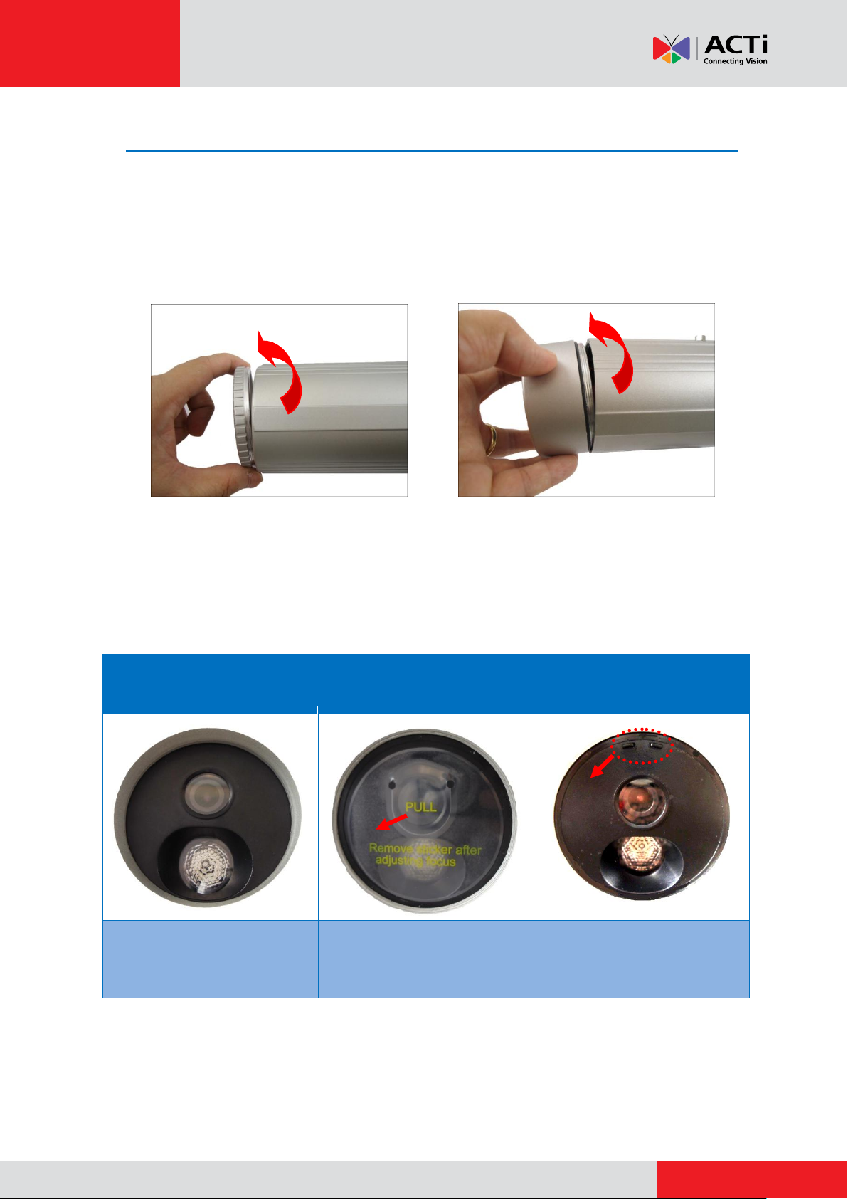
Design #1
Plain Front Cover
Design #2
Front Cover with Sticker
Design #3
Front Cover with Tabs
Detach the front cover using an
adhesive tape or a suction cup
(not included in the package).
Pull the plastic tab to detach the
front cover.
Using pliers, pull by the tabs to
detach the front cover.
How to Adjust Focus
This section describes the procedures in adjusting the viewing angle and focus of the different
camera models under the Bullet with Bundled Removable Bracket series.
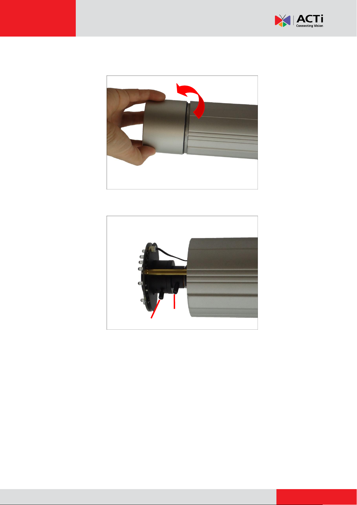
D3x / E3x Series
1. Remove the front cover ring.
D3x Series E3x Series
2. Remove the front cover (for D3x series only).
The D3x camera models have three (3) designs. Check your camera design to know the
suitable step in removing the front cover.
NOTE: For D3x cameras with Design #2, remove the whole sticker from the front cover after
adjusting the focus. The sticker cannot be reattached to the front cover. If the focus needs to
be adjusted in the future, use a suction cup or adhesive tape to detach the front cover.
50
Page 51
www.acti.com
Installation Guide
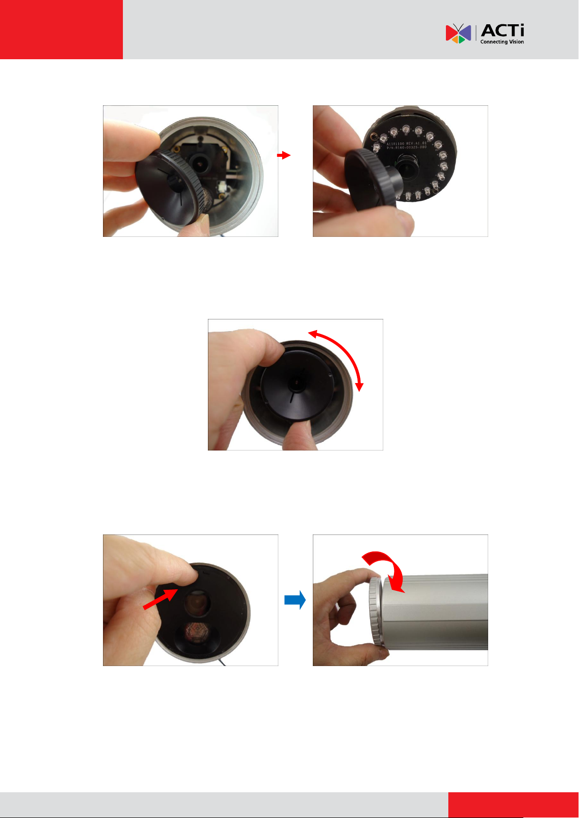
3. Attach the lens focus tuner to the lens.
D3x Series E3x Series
4. Adjust the focus based on the live view of the camera (see How to Access the Camera Live
View on page 42 to view the camera).
5. After adjusting the focus, remove the focus lens tuner.
6. Attach the front cover.
For D3x series, attach the front cover and the front cover ring.
CAUTION: The front cover and front cover ring must be tightly closed to ensure water or dust
does not go through any opening.
51
Page 52
www.acti.com
Installation Guide
Focal Length
Focus
D4x / E41 / E41A / E42 / E42A / E43 / E43A Series
1. Open the front cover.
2. Based on the live view from the camera, adjust the focal length and focus of the target area.
3. When done, close the front cover.
CAUTION: The front cover must be tightly closed to ensure water or dust does not go through
any opening.
52
Page 53
www.acti.com
Installation Guide
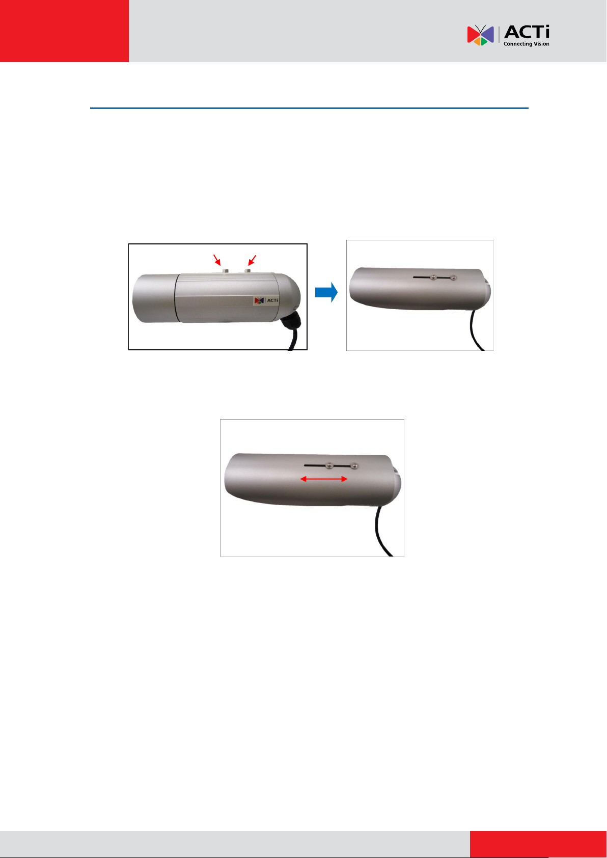
How to Attach the Sunshield
The use of sunshield is optional if the camera will be installed indoors. However, if the camera will
be installed outdoors, attach the sunshield to protect the lens from all types of weather and
lighting conditions.
1. Attach the sunshield onto the screw nuts using the supplied screws and washers.
2. Slide to adjust the sunshield to cover the lens as far as possible but out of the camera’s live
view.
3. Tighten the screws to fix the position of the sunshield.
53
Page 54
www.acti.com
Installation Guide
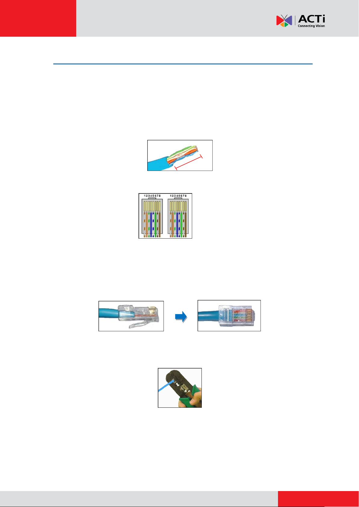
2. Cut about 1 inch into the plastic sheath from the end of the cable.
3. Unwind the wires and arrange them according to the color sequence below.
1) Stripe Orange
2) Orange
3) Stripe Green
4) Blue
5) Stripe Blue
6) Green
7) Stripe Brown
8) Brown
4. Pinch the wires between your fingers and straighten them out.
5. Use the scissors to make a straight cut across the wires ½ inch from the cut end.
6. With the RJ-45 connector tab facing down, push the wires into the connector all the way to
the end.
7. Place the connector into the crimping tool, and cinch down to secure the RJ-45 connector
to the Ethernet cable.
8. Repeat the same procedures to attach the other end.
1 inch
How to Make an Ethernet Cable
1. Prepare the following tools:
Ethernet cable without connectors
RJ-45 Connector (x2)
RJ45 Crimping Tool
Scissors
54
Page 55

www.acti.com
Installation Guide
Safety Information
Read these instructions
You should read all the safety and operating instructions before using this product.
Heed all warnings
You must adhere to all the warnings on the product and in the instruction manual. Failure to follow
the safety instruction given may directly endanger people, cause damage to the system or to
other equipment.
Trademarks
All names used in this manual are probably registered trademarks of respective companies.
Liability
Every reasonable care has been taken during the writing of this manual. Please inform your local
office if you find any inaccuracies or omissions. We cannot be held responsible for any
typographical or technical errors and reserve the right to make changes to the product and
manuals without prior notice.
Cleaning
Disconnect this video product from the power supply before cleaning.
Attachments
Do not use attachments not recommended by the video product manufacturer as they may cause
hazards.
Do not use accessories not recommended by the manufacturer
Only install this device in a dry place protected from weather
Servicing
Do not attempt to service this video product yourself. Refer all servicing to qualified service
personnel.
55
Page 56

www.acti.com
Installation Guide
Damage Requiring service
Disconnect this video product from the power supply immediately and refer servicing to qualified
service personnel under the following conditions.
1) When the power-supply cord or plug is damaged
2) If liquid has been spilled, or objects have fallen into the video product.
3) If the inner parts of video product have been directly exposed to rain or water.
4) If the video product does not operate normally by following the operating Instructions in this
manual. Adjust only those controls that are covered by the instruction manual, as an improper
adjustment of other controls may result in damage, and will often require extensive work by a
qualified technician to restore the video product to its normal operation.
Safety Check
Upon completion of any service or repairs to this video product, ask the service technician to
perform safety checks to determine if the video product is in proper operating condition.
56
 Loading...