

Page 1

MegaPixel IP Outdoor Rugged Dome
(with DC 12V / PoE)
ACM-7411 series
Ver. 081218
Hardware User’s Manual
Megapixel IP D/N Vandal Proof PoE
Outdoor Fixed Dome
ACM-7411
Ver. 120315
Hardware User’s Manual
Page 2

Page 3

0
Full D1 CAM-7200 series
CAM-5200
User’s Manual
0 PRECAUTIONS
1. Read these instructions
All the safety and operating instructions should be read before the product is
operated.
2. Heed all warnings
All warnings on the product and in the instruction manual should be adhered to.
The symbol indicates the following items, please carefully read the
description next to each symbol.
a. Failure to follow the safety instruction given may directly endanger
people, cause damage to the system or to other equipment.
b. The requirements to make this device work, including hardware,
computer settings, network settings, and operation procedures.
c. The tips to make using this device easier, more convenient and more
efficient.
3. Servicing
Do not attempt to service this video product yourself as opening or removing
covers may expose you to dangerous voltage or other hazards. Refer all servicing
to qualified service personnel.
Trademarks
All names used in this manual for hardware and software are probably registered
trademarks of respective companies.
Liability
Every care has been taken during writing this manual. Please inform your local office
if you find any inaccuracies or omissions. We cannot be held responsible for any
typographical or technical errors and reserve the right to make changes to the product
and manuals without prior notice.
FCC/CE Regulation
NOTE: This equipment has been tested and found to comply with the limits for a
Class A digital device, pursuant to Part 15 of the FCC Rules. These limits are
designed to provide reasonable protection against harmful interference when the
equipment is operated in a commercial environment. This equipment generates, uses,
0-1
Page 4

and can radiate radio frequency energy and, if not installed and used in accordance
with the instruction manual, may cause harmful interference to radio communications.
Operation of this equipment in a residential area is likely to cause harmful
interference in which case the user will be required to correct the interference at his
own expense.
0-2
Page 5

Table of Contents
0 PRECAUTIONS________________________________________________ 0-1
Trademarks ________________________________________________________________ 0-1
Liability ___________________________________________________________________ 0-1
FCC/CE Regulation __________________________________________________________ 0-1
1 INTRODUCTION ______________________________________________ 1-1
1.1 Package Contents _______________________________________________ 1-1
1.2 Features and Benefits ____________________________________________ 1-2
1.3 Safety Instructions ______________________________________________ 1-4
1.4 Physical Description _____________________________________________ 1-6
2 Installation Procedure ___________________________________________ 2-9
2.1 Connect the IP Outdoor Rugged Dome _____________________________ 2-9
2.1.1 Remove the cover ____________________________________________________ 2-9
2.1.2 Insert the cable ______________________________________________________ 2-10
2.1.3 Connect cables to connectors ___________________________________________ 2-10
2.1.4 LED Description ____________________________________________________ 2-11
2.2 Mount the IP Outdoor Fixed Dome (Surface) _______________________ 2-12
2.3 Mount the IP Outdoor Fixed Dome (Flush) _________________________ 2-13
2.4 Mount the IP Indoor Fixed Dome (Wall) ___________________________ 2-14
2.5 How to Do the Waterproof Installation ____________________________ 2-15
3 Adjust the camera______________________________________________ 3-18
3.1 Adjust zoom and focus __________________________________________ 3-18
3.2 Adjust camera functions _________________________________________ 3-18
4 Product Specification ___________________________________________ 4-19
0-3
Page 6

Page 7
1-1
1
1 INTRODUCTION
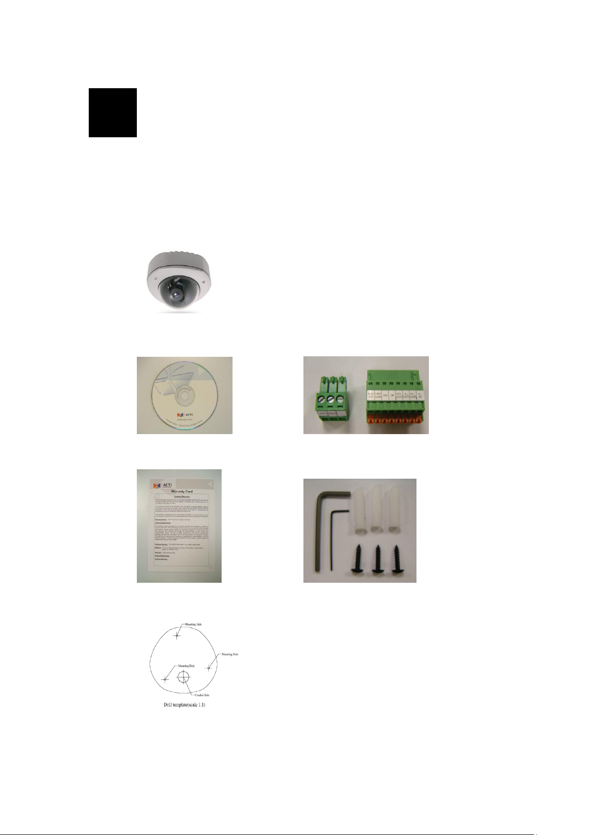
1.1 Package Contents
ACM-7411 series
(DC12V / PoE)
Product CD Terminal Blocks for Power, DI/O & Audio
Warranty Card Accessory
Drill Template
Page 8

1-2
1.2 Features and Benefits
This IP device is a cutting-edge digital video transmission device. It can
compress and transmit real time images with outstanding images quality
(SXGA, 1280x1024) at reasonable bandwidth through a standard TCP/IP
network. That is because it is Ethernet ready and has the powerful ARM9
SoC with excellent system performance to offer dual streams of
MPEG4/MJPEG, and both formats offer megapixel resolution. In addition,
with these powerful hardware platform, excellent SDK support and
powerful respective apparatuses (e.g. the transcoder), this IP device is your
best choice building up either conventional IP surveillance system or
intelligent IP surveillance system.
MPEG-4/MJPEG Dual Streaming
With excellent system performance, MPEG-4/MJPEG are supported. It
brings superior image quality not only 30 frame per second in full D1
resolution, but also offers up to 7 frames per second in SXGA
(1280x1024).
Automatic Frame Rate Control
This IP device supports automatic/manual streaming frame rate control,
especially for multiple clients’ concurrent access the same video
stream in different network bandwidth.
Digital Time Code Embedded
The “Digital Time Code Embedded” function is to embed the
recording time in the MPEG bit stream. Therefore, each image frame
has its respective time when it was recorded. It is very useful when
users want to find the video at an exact time or between a certain time
intervals.
DDNS Supported
This IP device supports DDNS (Dynamic Domain Name Server), users
can set this IP device at a virtual domain name (such as
cam1.Taipei.xxx) at dynamic IP. Everyone can use the virtual domain
name to view the video anywhere that has the access to the internet.
Build-in Hardware Motion Detection
No more external motion sensors are required. Each IP device can be
set up to 3 detection areas. By tuning the object size and sensitivity, it
is very reliable to fit into your environment. Besides, hardware motion
Page 9

1-3
detection delivers better sensitivity and responds faster than software
motion detection.
Bundle Powerful Surveillance Software
To extend the capabilities of this IP device, a powerful surveillance
program is included in the package and is very free to use. Users can
easily utilize the existing PC to be a digital video recorder. Schedule
recording and manual recording keep every important image recorded
in the local hard disk. Reliable and accurate motion detection with
instant warning makes you responsive in every condition. Quick and
simple search and playback function lets you easily find the images
you want.
Software Development Kit Support
This IP device can be integrated or controlled by user’s application
program through the Streaming Library or ActiveX control. With its
high level programming interface, software developer’s time and
efforts to is highly reduced.
Page 10

1-4
1.3 Safety Instructions
Don’t use the power supply with other voltages
This device is likely to be damaged or damage other equipments /
personnel, if you use a power supply with different voltage than the
one included with this device. All warranty of this product will be
voided in the situations above.
Don’t open the housing of the product
Cleaning
Disconnect this video product from the power supply before cleaning.
Attachments
Do not use attachments not recommended by the video product
manufacturer as they may cause hazards.
Don’t use accessories not recommended by the manufacturer
protected from weather
Servicing
Do not attempt to service this video product yourself as opening or
removing covers may expose you to dangerous voltage or other
hazards. Refer all servicing to qualified service personnel.
Damage Requiring service
Disconnect this video product from the power supply immediately and
refer servicing to qualified service personnel under the following
conditions.
1. When the power-supply cord or plug is damaged.
2. If liquid has been spilled, or objects have fallen into the video
product.
3. If the video product has been exposed to rain or water directly.
4. If the video product does not operate normally by following the
operating Instructions in this manual. Adjust only those controls
that are covered by the instruction manual as an improper
adjustment . Other controls may result in damage and will often
require extensive work by a qualified technician to restore the
video product to its normal operation.
Page 11

1-5
Safety Check
Upon completion of any service or repairs to this video product, ask
the service technician to perform safety checks to determine that the
video product is in proper operating condition.
Page 12

1-6
1.4 Physical Description
Page 13

1-7
1. Ethernet Port
PIN
NAME
DESCRIPTION
1
12V
DC Power Input
2
GND
Ground Pin
PIN
NAME
DESCRIPTION
1
DIO PW
DC12VIN
2
DIO GND
DGND
3
DO
DO1_TO_OUTSIDE
4
DI
DI1_FROM_OUTSIDE
5
AO_GND
DGND
6
A_OUT
Audio_OUT_LR
7
AI_GND
DGND
8
A_IN
Audio_IN
The IP device connects to the Ethernet via a standard RJ45
connector. Supporting NWAY, this IP device can auto detect the
speed of local network segment (10Base-T/100Base-TX
Ethernet).
2. Power Input
If your power input is DC12V. Please follow the description on
the connector to connect to power.
3. Power Input Audio & DIO input/output
Page 14

1-8
On (3s)
On
1s
Power On
About 20 Seconds
Stay On
Off (about 15s)
Off (10~15s)
Restore to Default
Complete
4. Reset Button
Step 1: Switch off IP device by disconnecting the power cable
Step 2: Press and continue to hold the Reset Button (with a sharp
tipped object, like a pen.)
Step 3: Reconnect the power cable while continuing to hold the
reset button. The red Power LED light will flash on for 3 second
first, turn off for about 15 seconds, flash on for another second
and turn off again. By this time the reset to default operation is
already completed. This will take around 20 seconds from
power up. You may then release the reset button. This length of
time fluctuates slightly with the environment. The Power LED
light will come back on and stay on after a few more seconds. The
unit will start up with factory default settings automatically.
5. Conduit Hole
These conduit holes are used for cables to go through.
Page 15

2-9
Surface mount
Flush mount
Wall mount
Pictures
Optional Bracket
required
●
●
2
2 Installation Procedure
There are three types of installation of this IP outdoor rugged dome series.
The mounting procedure can be divided into two parts,
1st: Connect the IP outdoor rugged dome series
2nd: Mount the IP outdoor rugged dome series
2.1 Connect the IP Outdoor Rugged
Dome
2.1.1 Remove the cover
Remove the dome cover with special hex wrench in the accessory bag.
Page 16

2-10
2.1.2 Insert the cable
There are two conduit holes, one is at the dome bottom and the other one is
at the side of rugged dome with plug. Remove the plug if your cable will go
through the one at the side of rugged dome
2.1.3 Connect cables to connectors
Please follow the instruction at Chapter 2: Physical Description, for how to
connect to each connector.
Page 17

2-11
2.1.4 LED Description
There are three LEDs in the system. They are indicators for power, fan and
heater respectively. According to operating temperature, the different LED
will be lighted for different situation.
Page 18

2-12
2.2 Mount the IP Outdoor Fixed Dome
(Surface)
Page 19

2-13
2.3 Mount the IP Outdoor Fixed Dome
(Flush)
Page 20

2-14
2.4 Mount the IP Indoor Fixed Dome
(Wall)
Page 21

2-15
2.5 How to Do the Waterproof
Installation
The following installation procedure makes the camera be water-resistant even for the
situations where the camera can easily be flooded by pouring rain.
The important part to focus on during the installation:
The protection of the cabling has to be done by a proper
flex conduit. The size of the flex conduit that matches
with the conduit gland is is 3/4” (trade size), or with
actual physical diameter of 26.441mm.
Have the Ethernet cable inserted through the
flex conduit together with RJ-45 connector.
You may also consider to do the RJ-45
connector crimping after pushing the cable
through the conduit.
Disassemble the conduit gland.
Slide the clamping nut around flex conduit some
10-20 cm away from the top. Fit the sealing insert
(made of rubber) to the top of the flex conduit.
On the camera side, decide which of the 2 possible holes you are going to use to
connect the flex conduit. There is one hole on the side, and one on the bottom.
Whichever you pick, remember to seal off the other one with the metal patch
(included in the camera set).
Page 22

2-16
Scenario 1 – using the side hole. Scenario 2 – using the bottom
hole.
Screw the body of the conduit gland into the camera and fix it with the lock nut
(included in the set of conduit gland that you purchased) from the inside of the
camera..
Connect the Ethernet cable to the camera’s network port. If you are not using PoE,
then please remember to pull the DC power cable through the flex conduit as well,
and connect to the camera at this point.
Push the head of the flex conduit, wrapped with sealing insert, into the body of the
conduit gland.
Page 23

2-17
Screw the clamping nut tightly onto the body of the conduit gland.
Adjust the viewing angle and focus of the camera and put the dome cover back on,
and tighten it by using the screws.
You have completed a fully waterproof installation!
Page 24

3-18
3
3 Adjust the camera
3.1 Adjust zoom and focus
Please adjust the camera direction first. Then move the focus and the zoom
lever at the picture 1 to adjust the zoom and the focus. Fix the zoom and
focus after adjusting.
3.2 Adjust camera functions
Refer to picture 1 for what can be adjusted and how to adjust.
Picture 1
1. focus lever
2. Zoom lever
3. Tilt adjustment screw
4. Image adjustment axis
5. Pan adjustment screw
Page 25

4-19
4
4 Product Specification
 Loading...