

Acson international AMAC50C, AMAC30C, AMAC20C, AMAC25C, AMAC60C Technical Manual
...
Technical Manual
AIR-COOLED
MINI CHILLER
AMAC 20-150 C/CR
A4AC 20-150 C
A4AC 60-150 CR
A5AC 20-55 CR

1. NOMENCLATURE .................................................................................................. 1
- PRODUCT LINE UP
2. FEATURES ............................................................................................................. 5
3. APPLICATION INFORMATION............................................................................... 7
- REFRIGERANT CIRCUIT DIAGRAM
- CHILLER PANEL CONTROLLER
- PRECAUTIONS AND INSTALLATION
4. SOUND DATA........................................................................................................57
5. SELECTION PROCESS ........................................................................................64
- WATER PRESSURE DROP VS FLOW RATE
- GLYCOL
6. ENGINEERING AND PHYSICAL DATA ................................................................. 67
- SPECIFICATIONS
TABLE OF CONTENTS
7. PERFORMANCE DATA ....................................................................................... 114
8. OUTLINE AND DIMENSION ............................................................................... 126
9. ELECTRICAL DATA ............................................................................................. 130
10. WIRING DIAGRAMS .........................................................................................138
11. SERVICING AND MAINTENANCE ....................................................................154
12. TROUBLESHOOTING ...................................................................................... 155
13. EXPLODED VIEW AND PART LIST .................................................................. 156

1. NOMENCLATURE
A 4 AC 20 C R
Brand
A :Acson
Refrigerant
“ “ : Omitted if R22
4 : R407C
5 : R410A
Model Name
AC : Air-Cooled Mini Chiller
Capacity Index
020 : 20,000 Btu/h
Chasis
C : C Series
Model Type
“ “ : Omitted if cooling only
R : Heat pump
1
PRODUCT LINE UP
AMAC-C/CR
AMAC
20C
25C
30C
40C
50C
60C
COOLING ONLY
HEATPUMP
80C
100C
120C
150C
20CR AXAB X X
25CR AXAB X X
30CR AXAB X X
40CR
50CR FXAC X X
60CR FXAC X X
80CR
100CR
120CR FXAC X X
150CR FXAC X X
Nomenclature
AXAC
AXAD
AXAC
AXAD
AXAC
AXAD
FXAC
FXAD
FXAC
FXAD
FXAC
FXAD
FXAE
FXAF
FXAE
FXAF
FXAC
FXAD
FXAC
FXAD
FXAC X X
FXAD X X
FXAE X X
FXAF X X
FXAE X X
FXAF X X
PCB-MC01
XX
XX
XX
XX
XX
XX
XX
XX
XX
XX
XX
XX
XX
XX
XX
XX
XX
XX
XX
XX
LCD Panel - Chiller Panel
CE Mark
Scroll Compressor
Rotary Compressor
CCH (Crank Case Heater)
Terminal Block
Magnetic Contactor
Water Tank + Pump
Without Tank / Pump Only
Expansion tank
Gold Fin
Antifreeze & Auto pump on
Phase Protector
XXXX
XXXX
XX XXX
XX XXX
XX XXX
XX XXX
XX XXX
XX XXX
XX XXX
XX XXX
XX XXX
XX XXX
XX XXXXXXXX X
XX XXXXXXX X
XX XXXXXXXX X
XX XXXXXXX X
XX XXXXXXXX X
XX XXXXXXX X
XX XXXXXXXX X
XX XXXXXXX X
XXXXX
XX XXXX
XX XXXX
XX XXXX
XX XXXX
XX XXXX
XX XXXX
XX XXXXXXXX X
XX XXXXXXXX X
XX XXXXXXXX X
XX XXXXXXXX X
XX XXXXXXXX X
XX XXXXXXXX X
XX
XX
XX
XX
XX
XX
XX
XX
XX
XX
XX
XX
X
X
X
X
X
X
X
XX
XX X
XX
XX X
XX
XX X
XX X
XXX X
XX X
XXX X
XX X
XXX X
XX X
XX X
XX X
XXX X
XXX X
XXX X
XXX X
Three Phase Fan Motor
Capillary Tube
TXV
2

A4AC-C/CR
A4AC
20C
25C
30C
40C
50C
60C
COOLING ONLY
HEATPUMP
80C
100C
120C
150C
20CR
25CR
30CR
40CR
50CR
60CR FXAB X X
80CR
100CR
120CR FXAD X X
150CR FXAD X X
Nomenclature
AXAC
AXAD
AXAC
AXAD
AXAC
AXAD
FXAC
FXAD
FXAC
FXAD
FXAC
FXAD
FXAI
FXAJ
FXAI
FXAJ
FXAG
FXAH
FXAG
FXAH
FXAE X X
FXAF X X
FXAE X X
FXAF X X
PCB-MC01
XX
XX
XX
XX
XX
XX
XX
XX
XX
XX
XX
XX
XX
XX
XX
XX
XX
XX
XX
XX
Classification
LCD Panel - Chiller Panel
CE Mark
Scroll Compressor
Rotary Compressor
CCH (Crank Case Heater)
Terminal Block
Isolator Switch
Magnetic Contactor
Water Tank + Pump
Pump Only
Expansion tank
Gold Fin
Antifreeze & Auto pump on
Phase Protector
XX
XX
XX X
XX X
XX X
XX X
XX X
XX X
XX X
XX X
XX X
XX X
XXXXXXXXXX X
XXXXXXXXX X
XXXXXXXXXX X
XXXXXXXXX X
XXXXXXXXXX X
XXXXXXXXX X
XXXXXXXXXX X
XXXXXXXXX X
XX X
XX X
XXXXXXXXXX X
XX X
XXXXXXXXXX X
XXXXXXXXXX X
XX
X
X
X
X
X
X
X
X
X
X
X
X
X
X
X
X
XX
X
XX
X
XX
X
XX
X
XX
X
XX
X
XX
X
XX
X
XX
X
XX
X
XX
X
XX
XX
XXXXXX X
XXXXXX X
XXXXXX X
X
X
XX
XX X
XX
XX X
XX
XX X
XX X
XXX X
XX X
XXX X
XX X
XXX X
XXX X
Three Phase Fan Motor
Capillary Tube
TXV
3

A5AC-CR
A5AC
20CR AXAA X X
25CR AXAA X X
30CR EXAB X X
40CR EXAC X X
50CR EXAC X X
HEATPUMP
55CR EXAC X X
Classification
Nomenclature
PCB - TC01
PCB - TC1.1r4
LCD Panel - Chiller Panel
CE Mark
Scroll Compressor
Rotary Compressor
CCH (Crank Case Heater)
Terminal Block
Isolator Switch
Magnetic Contactor
Water Tank + Pump
Pump Only
Expansion tank
Gold Fin
Antifreeze & Auto pump on
Phase Protector
Single Phase Fan Motor
Capillary Tube
XX
XX
XX
XX
XX
XX
X
X
X
X
X
X
XX
XX
X
X
X
X
XX X
X
XX X
X
XX XX
X
XX XX
X
XX XX
X
XX XX
X
TXV
4

2. FEATURES
REFRIGERANT CIRCUIT
Models AMAC/A4AC80~150C/CR has been designed with two separate refrigerant circuits, i.e. it has two
compressors. By doing so, the unit has part loading capabilities, i.e. 0-50-100% of rated capacity. This will
improve the reliability and energy efficiency of the unit, especially during low loading operations. Each circuit
is factory brazed and evacuated before accurately charged with refrigerant to ensure optimum performance.
Because each circuit is separated, there is no danger of cross-contamination should either one of the
compressor experiences a burnt-up. Each circuit is also equipped with a carefully sized thermostatic expansion
valve (for cooling only units) to give optimum performance characteristic. For the heatpump version, the
expansion process is done with capillary tubes.
SCROLL COMPRESSOR
Scroll Compressors are used (for model which is available) for the units (AMAC/A4AC20C/CR using rotary
compressor) to give quiet and reliable performance over a wide operating temperature range. However, in
order to protect the compressors from damage, a phase protector (for model which is available) is provided to
prevent the compressors from rotating in the wrong directions.
TANDEM COMPRESSOR
A5AC models are using R410A rotary compressors in tandem configuration. Tandem compressors are highly
efficient and cost saving. It reduces mechanical losses, minimize gas flow losses and turbulence. There are 3
steps capacity loading (0-40-60-100%) for A5AC40/50CR and 2 steps capacity loading (0-50-100%) for A5AC30/
55CR.
CONDENSER FAN MOTOR
Models AMAC/A4AC80~150C/CR is equipped with two high air flow propeller fan blades which are made of
metal. The fans are driven vertically by weather proof motors which are single phase type.
EVAPORATOR
The heat exchanger is made of stainless steel plates closely arranged and brazed together (BPHE) to ensure
high heat exchange efficiency. For models AMAC/A4AC80~150C/CR, the water flow through the BPHE in a
channel on its own, while because of the two compressors, the refrigerant flows through another two separate
channels. The refrigeran t will either be in a counter-flow or parallel-flow with respect to the water, depending
on the mode of operation (cooling or heating).
SAFETY PROCETECTION
The safety protections provided for the mini chiller are:
a) High and low pressure switches
b) Differential water flow switch
c) Compressor, water pump and fan motor overload protectors
d) Anti-freeze protection sensor
During abnormal condition, chiller panel controller will turn off the unit and then display the faults of operation.
WATER TANK AND PIPING CONNECTION
The models A4AC/AMAC80~150C/CR does not come with a water buffer tank. However, the unit does come
with an 8 liters expansion tank. Besides that, an optional 135L hydraulic tank is also available.
The external water piping connection can be made either from the left or right side of the unit. Connection is
done with Ø1-1/4 “ female thread couplings for both supply and return pipes.
Meanwhile, AMAC/A4AC20~60C/CR does come with a 22 L or 40 L (refer to specification) water buffer tank.
5

ANTIFREEZE PROTECTION
The chiller unit has several anti-freeze protection features:
1. Brazed plate heat exchanger anti-freeze
The BPHE has a strip heater around it to prevent water freezing inside
2. Auto mode
The chiller controller will force on the unit to the heat mode if the outdoor ambient air temperature
becomes too cold.
MAINTENANCE
In order to facilitate of the controller, a rocker switch is provided to power-off the supply to the PCB. However,
switching off the switch will not disconnect the main incoming power supply to the chiller unit.
6
3. APPLICATION INFORMATION
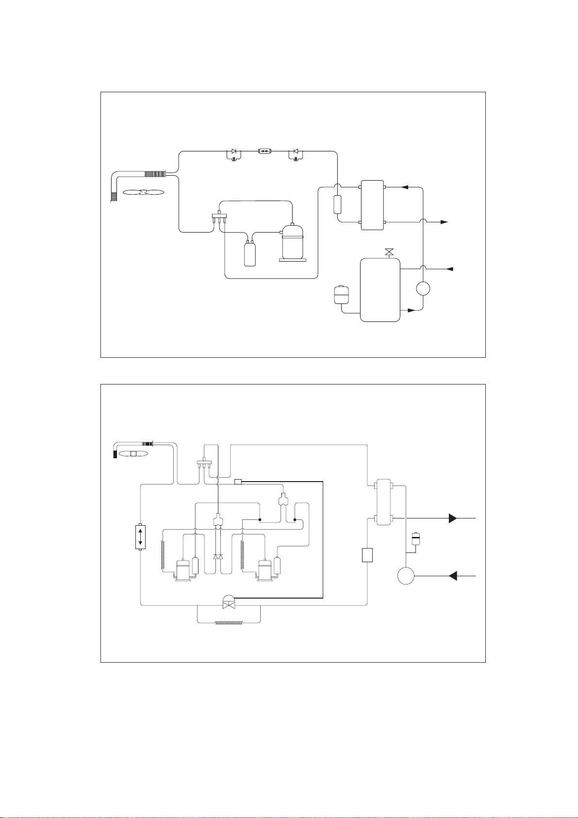
REFRIGERANT CIRCUIT DIAGRAM
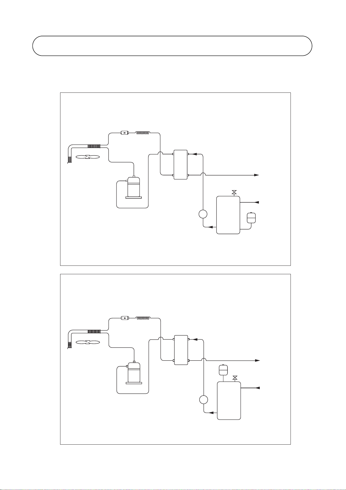
A4AC / AMAC 20C / 25C / 30C
Water / Refrigerant Circuit Diagram
FIL TER
DRIER
CAP TUBE
BPHE
AUT O PRESS RELIEF V ALVE
WATER
OUT
COMPRESSOR
WATER PUMP
P
WATER ST ORAGE
TANK
A4AC / AMAC 40C / 50C / 60C
Water / Refrigerant Circuit Diagram
FIL TER
DRIER
CAP TUBE
BPHE
EXP ANSION
COMPRESSOR
WATER
IN
EXP ANSION
TANK
PART NO : 70-03-4-067460
WATER
OUT
TANK
AUT O PRESS RELIEF V ALVE
WATER
IN
WATER PUMP
7
P
WATER ST ORAGE
TANK
PART NO : 70-03-4-087461
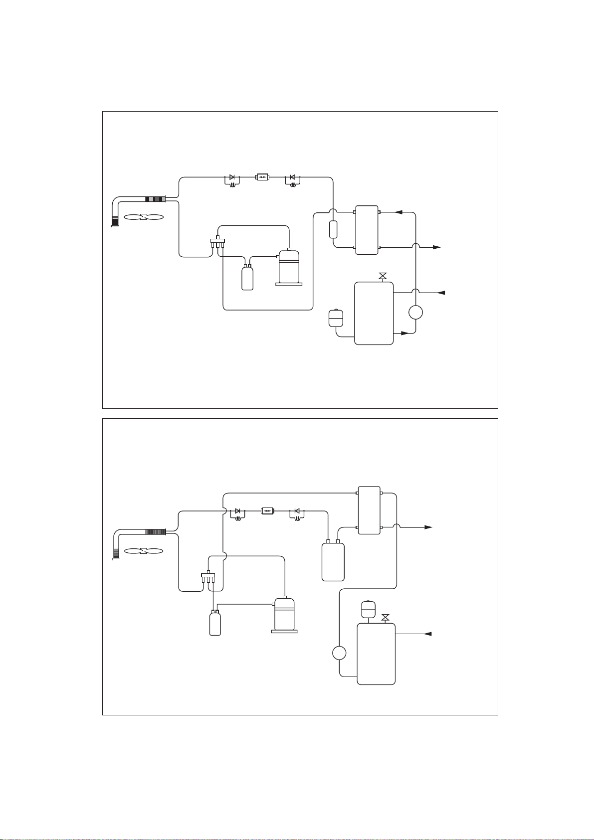
A4AC / AMAC 20CR / 25CR / 30CR
Water / Refrigerant Circuit Diagram
CHECK
VALV E
HEATING
CAP
TUBE
SUCTION
ACCUMULATOR
FILTER
DRIER
CHECK
VALV E
COOLING
CAP
TUBE
COMPRESSOR
EXPANSION
TANK
BPHE
CHARGE
COMPENSATOR
AUTO PRESS RELIEF VALVE
WATER STORAGE
TANK
PART NO : 70-03-4-067458
AMAC 40CR / 50CR, A4AC/ AMAC 60CR
Water / Refrigerant Circuit Diagram
WATER
OUT
WATER
IN
P
HEATING
SUCTION
ACCUMULATOR
CHECK
VALV E
CAP
TUBE
FILTER
DRIER
COOLING
COMPRESSOR
CHECK
VALV E
CAP
TUBE
WATER PUMP
LIQUID
RECEIVER
P
WATER STORAGE
BPHE
TANK
EXPANSION
TANK
AUTO PRESS RELIEF VALVE
PART NO : 70-03-4-067459
WATER
OUT
WATER
IN
8

A4AC / AMAC 80C / 100C / 120C / 150C
Water / Refrigerant Circuit Diagram
FIN TUBE
HEA T EXCHANGER
(SYSTEM 1)
FIL TER DRIER FIL TER DRIER
COMPRESSOR COMPRESSOR
A4AC / AMAC 80CR / 100CR / 120CR / 150CR
THERMOST ATIC
EXP ANSION
VA L V E
BRAZED PLA TE
HEA T EXCHANGER
WATER
OUTLET
WATER
INLET
THERMOST ATIC
EXP ANSION
VA L V E
FIN TUBE
HEA T EXCHANGER
(SYSTEM 1)
Water / Refrigerant Circuit Diagram
FIN TUBE
HEA T EXCHANGER
(SYSTEM 1)
HEA TING
FIL TER
DRIER
COOLING
WATER
OUT
CAP
TUBE
CAP
TUBE
HEA TING
TUBE
COOLING
TUBE
CHECK
4-WAY VAL VE
COMPRESSOR COMPRESSOR
SUCTION
ACCUMULA TOR
VA L V E
CHECK
VA L V E
LIQUID
RECEIVER
CAP
CAP
WATER
FIL TER
DRIER
IN
LIQUID
RECEIVER
CHECK
VA L V E
CHECK
VA L V E
HEA T EXCHANGER
SUCTION
ACCUMULA TO R
FIN TUBE
(SYSTEM 2)
4-WAY VA LVE
PAR T NO : 70-03-4-056764
9
A5AC 20CR / 25CR
Water / Refrigerant Circuit Diagram
CHECK
VALV E
FILTER
DRIER
CHECK
VALV E
WATER / REFRIGERANT
HEATING
CAP
TUBE
SUCTION
ACCUMULATOR
COOLING
CAP
TUBE
COMPRESSOR
EXPANSION
CHARGE
COMPENSATOR
TANK
BPHE
AUTO AIR VENT
WATER STORAGE
TANK
A5AC 30CR
Water / Refrigerant Circuit Diagram
WATER
OUT
WATER
IN
WATER PUMP
P
PART NO : 70-03-4-080547
FILTER
DRIER
OIL
RETURN
TUBE
4WV
COMPRESSOR 1
CHECK
VALV E
TXV
OIL
RETURN
TUBE
COMPRESSOR 2
TWIN TUBE
JOINT
CHARGE
COMPENSATOR
BPHE
WATER OUT
EXPANSION TANK
WATER IN
PUMP
10

W
A5AC 40 / 50CR
Water / Refrigerant Circuit Diagram
4WV
SUB ACCUMULATOR
TWIN TUBE
JOINT
BPHE
WATER
OUT
FILTER
DRIER
RETURN
TUBE
WATER / REFRI
OIL
COMPRESSOR 1
4WV
CHECK
VALV E
TXV
OIL
RETURN
TUBE
COMPRESSOR 2
A5AC 55CR
LIQUID RECEIVER
Water / Refrigerant Circuit Diagram
BPHE
SUB ACCUMULA TO R
TWIN TUBE
JOINT
PUMP
EXPANSION
TTANK
WATER
WATER
OUT
IN
FIL TER
DRIER
OIL
RETURN
TUBE
COMPRESSOR 1
CHECK
VA LV E
TXV
OIL
RETURN
TUBE
COMPRESSOR 2
11
LIQUID RECEIVER
PUMP
EXP ANSION
TANK
WATER
IN

CHILLER PANEL CONTROLLER
1. SAFETY CONSIDERATION
Only specially trained and technicians and installers are authorized to install and service this
equipment..
1.1 General Installation Recommendations
• Only supply DC voltage (9-17V, typically 12V, maximum current 200mA) as a power source
to the device.
• Input contact voltage supply should limit to 12VDC or 24VAC.
• Isolated all the low voltage wiring (communication bus, etc) from high voltage power supply
wiring.
2. GENERAL DESCRIPTION
2.1 General
The chiller panel controller is designed to control the chiller operation. This device allows the
user to have customized control for each connected unit.
2.2 Features
The requirements of user friendly and easy to use have been taken into account in designing
this chiller panel controller. It can do the task as follow:
• Whole system configuration
• Unique parameter settings
• Operation status display
• Tracing fault record (easy in hardware troubleshooting)
The display is shown in an 8-lines graphical LCD display. There are 8 dedicated keys available
in the panel,
• Menu selection
• Navigation on the screen
• Modification of the selected value
During first start-up, the panel will have a default configuration (timer schedule, set point,
miscellaneous settings, etc) User can do the changes on that particular configuration later.
2.3 Panel Position
The chiller panel controller can be installed anywhere, as long as it is easy to accessed by
authorized personnel.
The requirements of installation are:
• Avoid exposure to shocks
• Avoid any source of electromagnetic pollution
• Avoid installation on uneven vertical surface
2.4 Operation Environmental Condition
• Temperature:
-10°C to 65°C operating temperature
-20°C to 85°C storage temperature
• Relative Humidity:
0 to 95% non-condensing
12
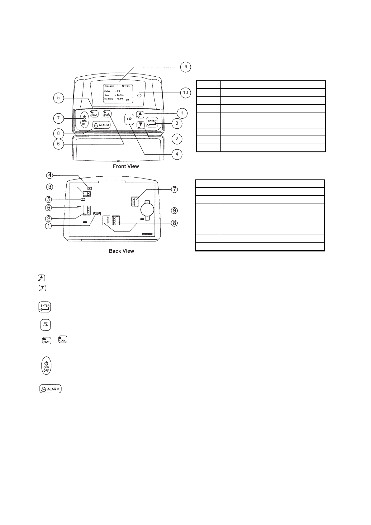
3. HARDWARE DESCRIPTION
Legend
3.1 Key Explanation
1 & 2
Navigation key
3 Execute instruction key
4 Cancel instruction key
5 Switching to heat mode shortcut key
6 Switching to cool mode shortcut key
7 Toggle ON/OFF shortcut key
8 Show alarm k ey
9 Graphical LCD display
10 ON/OFF indicator
Legend
1 & 2
Chiller terminal unit connection
3 Not avai lab le
4 CMOS rset jumper (JH2)
5 Chiller bus resist or configuration (JH3)
6 Not avai lab le
7 Not avai lab le
8 Not avai lab le
9 Not avai lab le
10 Bac kup battery
The 2 navigation keys permit item selection and modifying the selected value.
ENTER key is used to execute the navigation instruction
ESC key is used to cancel the navigation instruction
Shortcut key to switch the operation mode in the summary pages
Shortcut key to trigger ON/OFF in the summary pages
Shortcut key to show fault / alarm in the summary pages
13

4. INSTALLATION
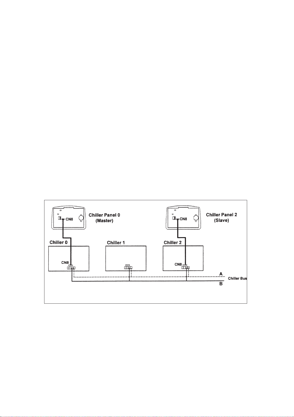
4.1 Chiller Bus
Supported up to 50 units of Chiller
Chiller 0 Chiller 1 Chiller 2
5 way wire (CM8)
Chiller
Communication bus
Chiller Panel 0 Chiller Panel 1
(Master) (Slave)
Chiller Network
Chiller panel needs to be energized with +12Vdc. The 5 way wires that provided is once on the easiest
solution to establish a communication between the panel and chiller main board (CN8-CN8). If the 5-way
wires socket has been occupied in main board, just using 2 insulation wired are needed to establish a
communication between panel and chiller main board.
Chiller panel can support maximum up to 50 units of chiller. In the chiller network, duplication of main board
unit address is not allowed. Each chiller main board should have their unique unit address (0-50).
For first time running, user need to assign a unique unit address to each main board in the chiller network.
User should follow the procedure below:
• Only power ON one main board at once time. Make sure not others main boards are energize.
• By using the panel connected to the main board.
<ENT ER> <ENT ER>
Summary Pages Main Menu Setting Menu
<ENTER>
G7 Unit No 1. General Set Paraameter
<ENT ER> <ENT ER>
key in "0001" as p assw ord
• Key in unique unit address and press ENTER to execute.
• De-energized the main board and repeat the procedures again all the main boards have been
assigned a unique unit address.
IMPORTANT : Do not assign a same unit address to more than one chiller main board.
RECOMMENDATION : Please select a coherant model (G1 Model) to all the chiller main boards in
the same network.
14
4.2 Others Configuration
• JH2 in chiller panel should let it open (put the jumper header on one pin only) all the time
unless user need to do CMOS reset to that particular panel.
• JH3 should let it open (put the jumper header on one pin only) all the time as well.
• Remember to put in the coin cell battery on the panel. Without the backup battery, the panel will
always reset the time to 12:00am, 1st Jan 2000.
4.3 Installation of the Chiller Panel Controller
• Disconnect the unit and ensure no others unit energy source that supplies the panel.
• Open the rear panel of the Chiller Panel (insert a ‘flat-head’ screwdriver in the top joint of main
casing with rear panel to open the real panel).
• Pass the necessary wires of the panel across the large opening in the rear panel. Place the rear
panel flat support against the wall and make marks on the wall through the four installation holes
(inner and outer).
• Drill four appropriate holes in the marked places.
• Attach the rear panel to the wall and put on the screws on it. Ensure that all cables are passed
through the hole of the rear panel.
• Connect the wires to the corresponding terminal according to the wiring bus network. The
power supply and communication wires must be correctly connected to ensure that the
panel works.
• Close the chiller panel (ensure the bottom joint is aligned for the casing, then complete others joint
part. Ensure that the contacts at the back of the panel are aligned with each others).
Bus Wiring Diagram
15

5. SOFTWARE DESCRIPTION
5.1 Introduction
The Chiller Panel Controller can be used to control / display the status of Chiller.
Status viewing:
• ON/OFF status
• Mode (Cooling / Heating/ Boiling)
• Mode set temperature
• Compressor status (ON/OFF/ DEFROST)
• Water in, Water Out, Outdoor air and Panel temperature
• Chiller model (Chiller, Heat Pump, Chiller/ Boiler, Chiller+Boiler, Heat Pump/Boiler, Heat Pump+
Boiler
• Advance parameter settings
• Defrost sensor temperatures
• Compressor discharge sensor temperatures
• Compressor run times
• Incoming alarm/ fault/ error
Status settings:
• ON/OFF switching
• Mode setting (Cooling / Heating/ Boiling)
• Mode set temperature
• Manual entering defrost
• Advance parameter settings
• Password changing
• Panel option setting (Backlight, Alarm Buzzer, Screen saver, Contrast, Brightness, temperature
unit)
• Time and date settings
• Clearing compressor run time
16
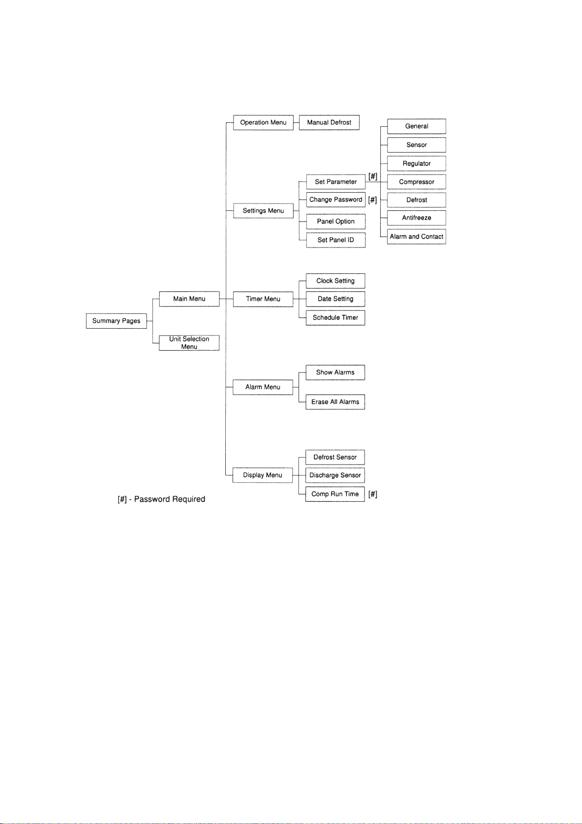
5.2 Menu Structures
Menu Structure Diagram for Chiller
17

5.3 Chiller Menu Structure
5.31 Summary Pages
There are 4 pages in [Summary Pages]. Press UP or DOWN for page scrolling. Press ENTER to go to
[Main Menu]. Time and date are shown on top of each page. Beside that, the bottom of each page shows
current control unit of the Chiller.
For example: [00] - Chiller Panel controls Chiller ID 0 currently
[03] - Chiller Panel controls Chiller ID 3 currently
[All] - Chiller Panel controls all Chiller currently
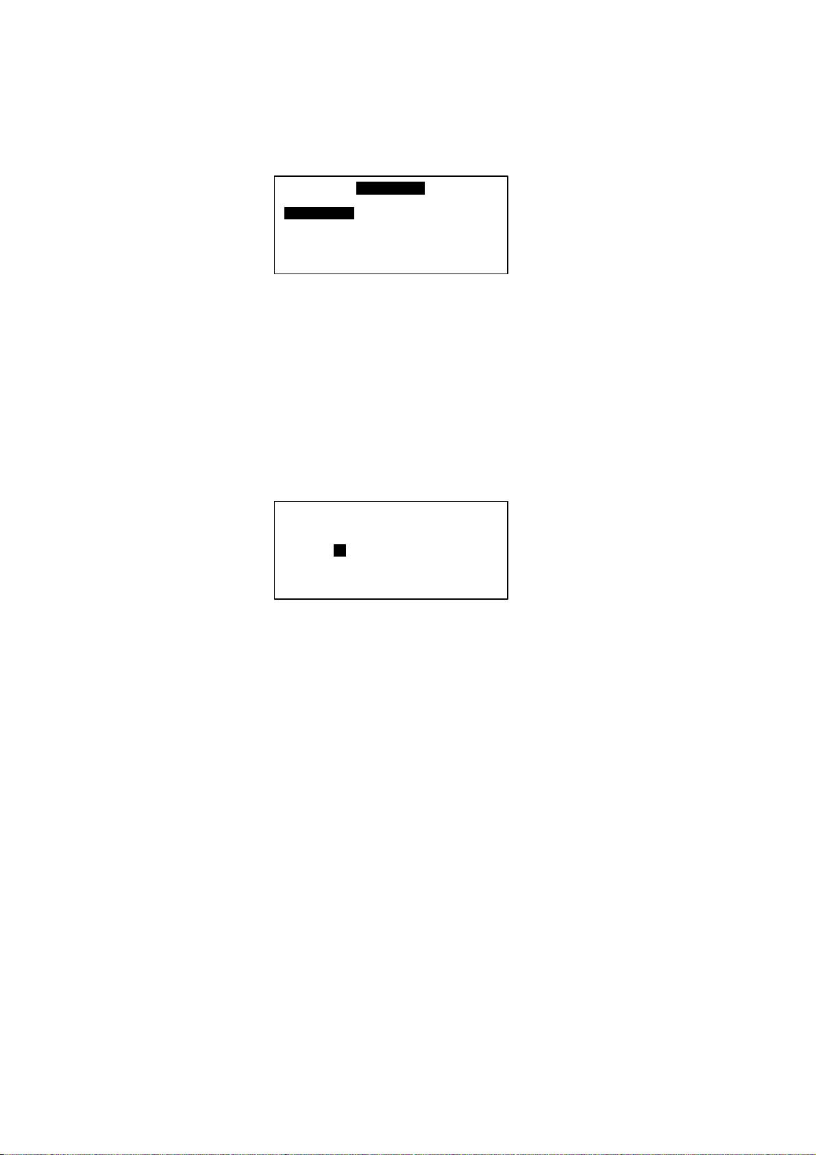
1st page: Display ON/OFF status, Mode settings and Temperature settings.
01/01/2000 12:00am
Status : ON
Mode : Cooling
Cool Temp : 12.0°C
[00]
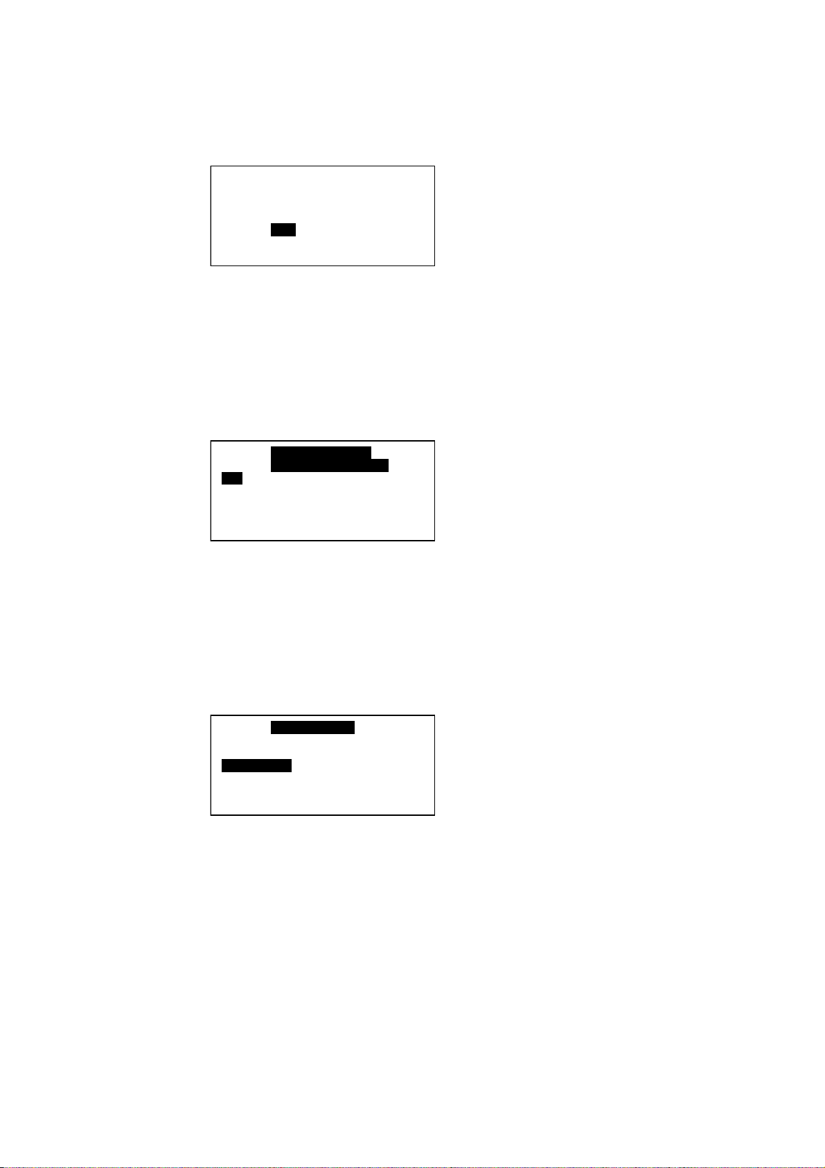
2nd page: Display Compressor status.
01/01/2000 12:00am
Compressor : ON
[00]
3rd page: Display Water In, Water Out, Outdoor air and Panel temperature
01/01/2000 12:00am
Water In :19.8°C
Water Out : 25.6°C
Outdoor Air : 32.2°C
Panel : 20.5°C
[00]
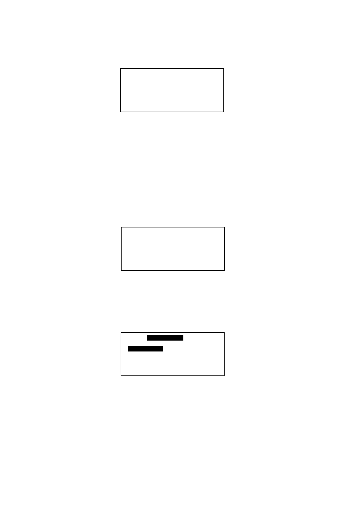
4th page: DisplayChiller model, Compressor No. and Chiller ID.
01/01/2000 12:00am
Model : Chiller
No. Comp : 1 Comp
Unit No : 0
18

5.3.2 Main Menu
Press ENTER in [Summary Pages] to go into this menu
MA I N MENU
Operating Menu
Setting Menu
Ti me r Me nu
A larm Men u
Dis play Menu
There are 5 sub menus in [Main Menu]. Press UP or DOWN to select sub menus, ENTER to enter into
the sub menu or press ESC to exit to [Summary Pages]
5.3.2.1 Operation Menu
Select [Operation Menu] in [Main Menu] and press ENTER to go into this menu.
OPERAT ION MENU
Status : ON
Mode : Cooling
Cool Te mperature : 12.0° C
Heat Te mperature : 40.0° C
Some normal settings can be found here. Press UP or DOWN to select each settings, ENTER to start the
setting or press ESC here to exit to [Main Menu]
Settings : -ON/OFF unit
- Mode changing (Cooling/ Heating/ Boiling)
- Cooling temperature setting
- Manual Defrost Selection
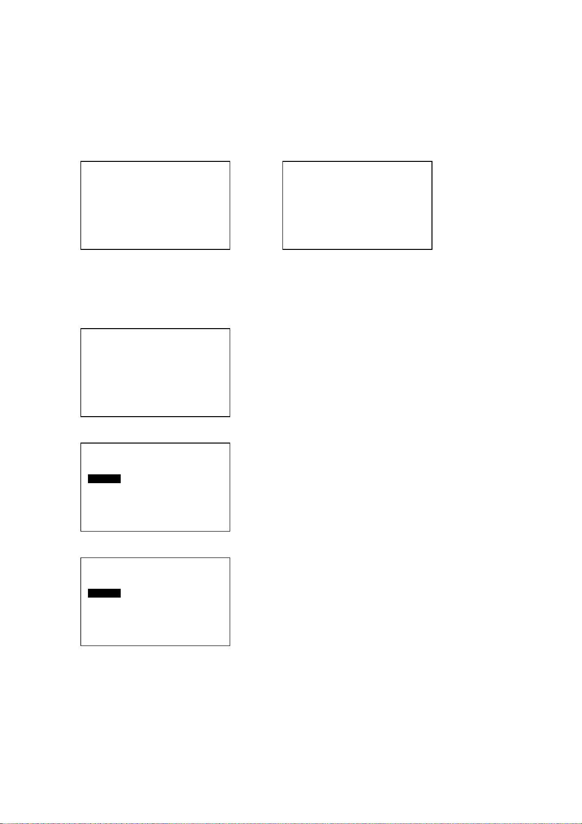
5.3.2.1.1 Manual Defrost
Select [Manual Defrost] in [Operation Menu] and press ENTER to go into this menu.
This menu lets user select one compressor to enter into defrost cycle manually, as long as the
environment fulfill the defrost requirement.
Def r ost Compres s or
Co mp 1
19

5.3.2.2 Settings Menu
Select [Settings Menu] in [Main Menu] and press ENTER to go into this menu.
SETTINGS MENU
Set Parameter
Change Passw ord
Panel Option
Set Panel ID
Some advance settings can be found here. Press UP or DOWN to select settings, ENTER to start the
setting or press ESC here to exit to [Main Menu].
Settings - Set Parameter
- Password Changing
- Panel Option
- Set Panel ID
5.3.2.2.1 Set Parameter
Select [Set Parameter] in [Settings Menu] and press ENTER to go into this menu.
1.General
2. Sensor
3. Regulator
4. Compressor
5. Def rost
6. Antif reeze
7. Alarm and Contact
There are 7 groups of advance parameters for user to set in this menu, Press UP or DOWN to
select the group, ENTER to go into the group or ESC to exit to [Setting Menu].
Settings:- General
- Sensor
- Regulator
- Compressor
- Defrost
- Antifreeze
- Alarm and Contact
5.3.2.2.2 Password Changing
Select [Password Changing] in [Setting Menu] and Press ENTER to go into this menu.
Please enter the
Old password ………..
0
- - - -
User can change the old password in this menu.
Press ESC to exit to [Settings Menu].
20

5.3.2.2.3 Panel Option
Select [Panel Option] in [Setting Menu] and Press ENTER to go into this menu.
Back light :
Buzzer : On
Scree n Saver : Disable
Timeout : 5m
Contrast : 50%
Br ig ht ness : Me dium
Temp Unit : ° C
: Nor m a l
User can do some miscellaneous for the panel. These settings would not affect whole system performance.
Settings - Toggle Backlight
- Alarm Buzzer
- Enable / Disable Screen Saver
- Screen Saver timeout
- Contrast display
- Backlight brightness
- Temperature unit
Press ESC to exit to [Settings Menu]
5.3.2.2.4 Set Panel ID
Select [Set Panel ID] in [Settings Menu] and press ENTER to go into this menu.
Ple ase enter the
Panel ID……
=> Unit 0
User can assign the ID no, to the panel.
Example: If ID no. 0 has been assigned, the panel acts like Master Panel Unit. It can choose to control
each Chiller in the network.
If other ID no. (1-50) has been assigned, the panel acts like Slave Panel Unit. It is dedicated to
one particular Chiller. It can only control the Chiller with same ID in the network.
Press [ESC] to exit to [Settings Menu]
21
5.3.2.3 Time Menu
Select [Time Menu] in [Main Menu] and press ENTER to go into this menu.
Cl o ck Se tting :
Dat e Setting
Time Schedule
Timer : Dis able
TIMER MENU
All the timer/ schedule settings are included in this menu. Press UP or DOWN to select each settings.
ENTER to start the setting or press ESC here to exit to [Main Menu].
Settings: - Set Clock
- Set Date
- Set Schedule ( 7 days Programmable Timer)
- Enable/ Disable Timer Schedule
5.3.2.3.1 Set Clock
Select [Clock Setting] in [Timer Menu] and press ENTER to go into this menu.
Se t Time :
hh: mm
00: 00
User can set the time in this menu. The time setting is in 24-hour format.
Pres [ESC] to exit to [Timer Menu].
22
5.3.2.3.2 Set Date
Select [Date Setting] in [Timer Menu] and press ENTER to go into this menu.
Set Time :
yyyy hh mm
2000 /01 / 01
User can set the date in this menu. The date is set according to sequence below:
(year) / (month) / (day)
Press [ESC] to exit to [Timer Menu].
5.3.2.3.3 Set Schedule
Select [Schedule Timer] in [Timer Menu] and press ENTER to go into this menu.
Timer 1 Timer2
Sun 0800 1600 _ _ _ _ _ _ _ _
Mon 0800 1600 _ _ _ _ _ _ _ _
Tue 0800 1600 _ _ _ _ _ _ _ _
Wed 0800 1600 _ _ _ _ _ _ _ _
ON OFF ON OFF
This is the 7 days programmable timer schedule menu. There are 2 ON/OFF events in one day. User can
choose to set each day of week (Sunday - Saturday) ON/OFF timer. Before this schedule carry their
effect to the Chiller, user need to set the [Timer] in [Timer Menu] to enable.
Press [ESC] to exit to [Timer Menu].
5.3.2.4 Alarm Menu
Select [Alarm Menu] in [Main Menu] and press ENTER to go into this menu.
ALARAM MENU
Show Alarms
Erase All Alarm
This place keeps records for all previous occurred fault/ alarms. User can view the alarm history and
clear
that record (alarm history) as well. The panel can keep up to 20 fault/ alarm records.
Press ESC to exit to [Main Menu]
23
5.3.2.4.1 Show Alarms
Select [Show Alarms] in [Alarm Menu] and press ENTER to go into this menu.
[Ch 0]
Alarm 1
Comp 1 over load
01/ 01/ 00 12:00am
User can view all the fault/ alarm records in this menu.
The record shows - Alarm type
- Alarm occurred date
- Alarm occurred time
- Alarm occurred unit (Chiller ID)
Beside that, user can erase the alarm record in this menu.
Press [ESC] to exit to [Alarm Menu].
5.3.2.4.2 Erase All Alarms
Select [Erase All Alarms] in [Alarm Menu] and press ENTER to go into this menu.
Are you sure ?
Press Enter to er ase,
or ESC to exit.
User can rase all the alarm / fault records at once in this menu.
Press [ESC] to exit to [Alarm Menu].
5.3.2.5 Dispaly Menu
Select [Display Menu] in [Main Menu] and press ENTER to go into this menu.
DISPL AY M ENU
De fr ost Se nsor
Dis char ge Sens or
Comp Run Time
This menu display Defrost Sensor temperature, Compressor Discharge sensor temperature and
Compressor Run Time. Beside that, user can clear each Compressor Run Time for Chiller.
Press [ESC] to exit to [Main Menu]
24

5.3.2.5.1 Defrost Sensor
Select [Defrost Sensor] in [Display Menu] and press ENTER to go into this menu.
De fr os t Se nsor
Comp 1 : 12.8° C
User can view the defrost sensor temperature for each compressor in the Chiller.
Press [ESC] to exit to [Display Menu]
5.3.2.5.2 Discharge Sensor
Select [Discharge Sensor] in [Display Menu] and press ENTER to go into this menu.
Dis ch arges Sens or
Comp 1 : 36.5° C
User can view the discharge sensor temperature for each compressor in the Chiller.
Press [ESC] to exit to [Display Menu].
5.3.2.5.3 Comp Run Time
Select [Comp Run Time] in [Display Menu] and press ENTER to go into this menu.
Comp Run Time
Comp 1 : 13579h
User can view the compressor run time for each compressor in the Chiller. Beside that, user can
clear each compressor run time in this menu. User needs to key in the correct password before
clearing the compressor run time.
Press [ESC] to exit to [Display Menu].
25

6. OPERATION USER MANUAL
6.1 Starting
Chiller panel can be set as Master or Slave panel unit. When the Panel ID is set to ‘0’, it acts like a Master
panel, whereas it is Slave panel if Panel ID is set to others number (1-50).
Chiller panel can control the Chiller if both ID no. (Panel ID and Chiller ID) are same.
For example: Panel ID 1 can only control Chiller ID 1
Master Panel can choose to control each Chiller or control all Chiller at once in the network.
For example : Panel ID 0 (master) can control Chiller ID 0 / ID 1/ ID 32 .... or all Chillers at once.
Panel ID can be set in Set Panel ID in Settings Menu.
Ple ase enter the
Panel ID ……
=> Unit 0
26
6.2 Chiller Operation Control
[00]
[00]
[00]
6.2.1 Starting
During power on for the Chiller Panel, it needs to take several times to collect information from the Chiller.
At this time, all the status will show “--”. Please ensure the particular Chiller exists in the network. When
the process is completed, user can start to control the Chiller using the panel.
01/ 01/ 2000 12:00am
Status : --
Mode : --
Cool Temp : --
01/ 01/ 2000 12:00am
Status : ON
Mode : Cooling
Cool Temp : 12° C
In gathering information process Gathering information completed
6.2.2 Changing Display Unit
Chiller Panel (Master) can choose to choose to control / display each Chiller status. This can be done in
[Summary Pages] only.
01/ 01/ 2000 12:00am
Status : ON
Mode : Cooling
Cool Temp : 12° C
Unit Selection :
Select All
Select One : 0
In [Summary Pages], press and hold ENTER buttom
(1 second) to go into [Unit Selection] menu.
Select “Select All” and press ENTER if user want to
control all Chilelr in the network, or select “Select One”
to control a particular Chiller. Press ESC to exit to
[Summary Pages].
Unit Selection :
Select All
Select One : 0
Select a Chiller ID via UP or DOWN and press ENTER
to confirm or ESC to cancel.
27
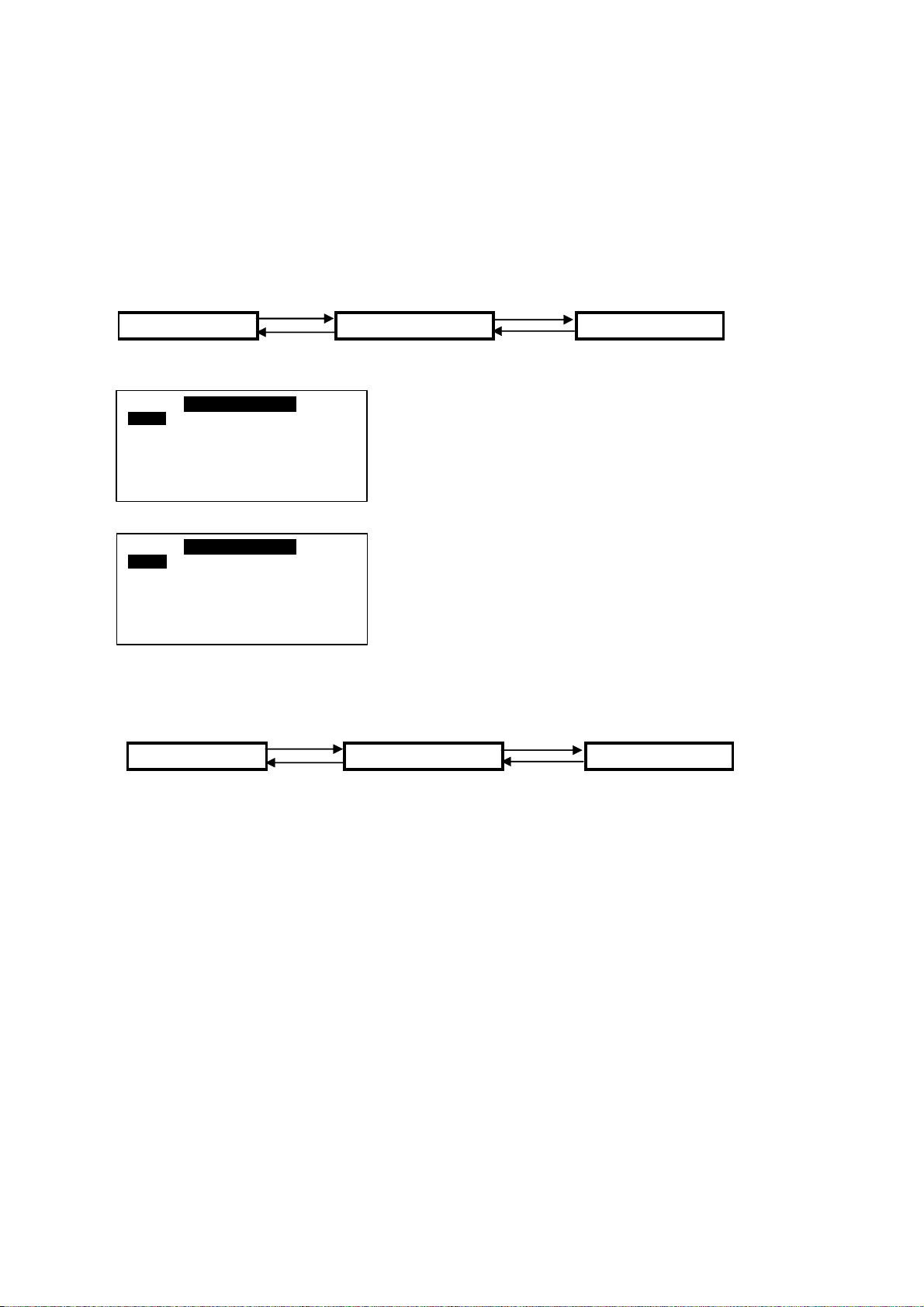
6.2.3 Switching ON/OFF
There are several ways to switch ON/OFF for the Chiller.
i) [Summary Pages]
Press and hold ON/OFF button (hold 1 second). Please note that the ON/OFF button will only function
in
[Summary Pages].
ii) [Operation Menu]
<ENTER> <ENTER>
Summary Pages Main Menu Operation Menu
<ESC> <ESC>
OPERATION M ENU
Stat us : O N
Mode : Cooling
Cool Temperature : 12.0° C
Heat Temperature : 40.0° C
OPERATION M ENU
Stat us : O N
Mode : Cooling
Cool Temperature : 12.0° C
Heat Temperature : 40.0° C
In [Operation Menu], select “Status” and press
ENTER.
Toggle ON/OFF via UP or DOWN button, and then
press ENTER to confirm the change or ESC to cancel.
iii) [Timer Menu]
<ENTER> <ENTER>
Summary Pages Main Menu Timer Menu
<ESC> <ESC>
7 days programmable time can turn chiller ON/OFF. User can set the schedule in this
[Timer Menu]. Please refer 6.2.11 (page 27) for schedule settings.
28
 Loading...