

Acson international A5DB125H-FMBNA, A5DB80H-AMBHA, A5DB200H2-FMBNA, A5DB250H2-FMBRA, A5DB150H-FMBNA Technical Manual
...
Technical Manual
SPLIT SYSTEMS
AIR CONDITIONER
DUCTED BLOWER
H SERIES
A5DB-H series
Cooling only [50Hz]
R410A
TM-5SB-H-AM-A4
SPLIT SYSTEMS AIR CONDITIONER
DUCTED BLOWER H SERIES
CONTENTS
1.
NOMENCLATURE
• Indoor
• Outdoor
• Product Line-Up
2. APPLICATION INFORMATION
• Operating Range
• Refrigerant Circuit Diagram
• Installation Guideline
3.
4.
5.
6.
7.
SOUND DATA
• Sound Pressure Level
• Sound Power Level
• NC Curv
SELECTION PROCESS
ENGINEERING & PHYSICAL DATA
PERFORMANCE DATA
• Calculation Steps
• Performance Tables
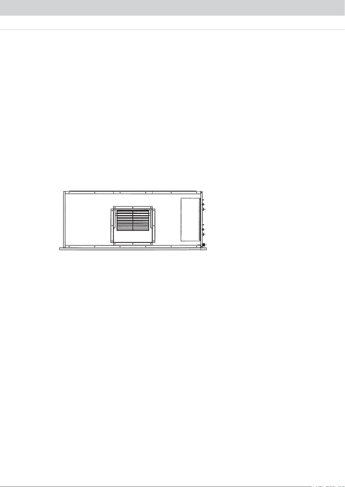
OUTLINE AND DIMENSION
8. WIRING DIAGRAMS
P.1
P.5
P.15
P.24
P.42
P.46
P.62
P.86
9. SERVICING AND MAINTENANCE
10. TROUBLESHOOTING
* All specifications stated in this technical manual are for Cooling Only unit.
Please contact us for more information about Heat Pump unit.
P.88
P.90
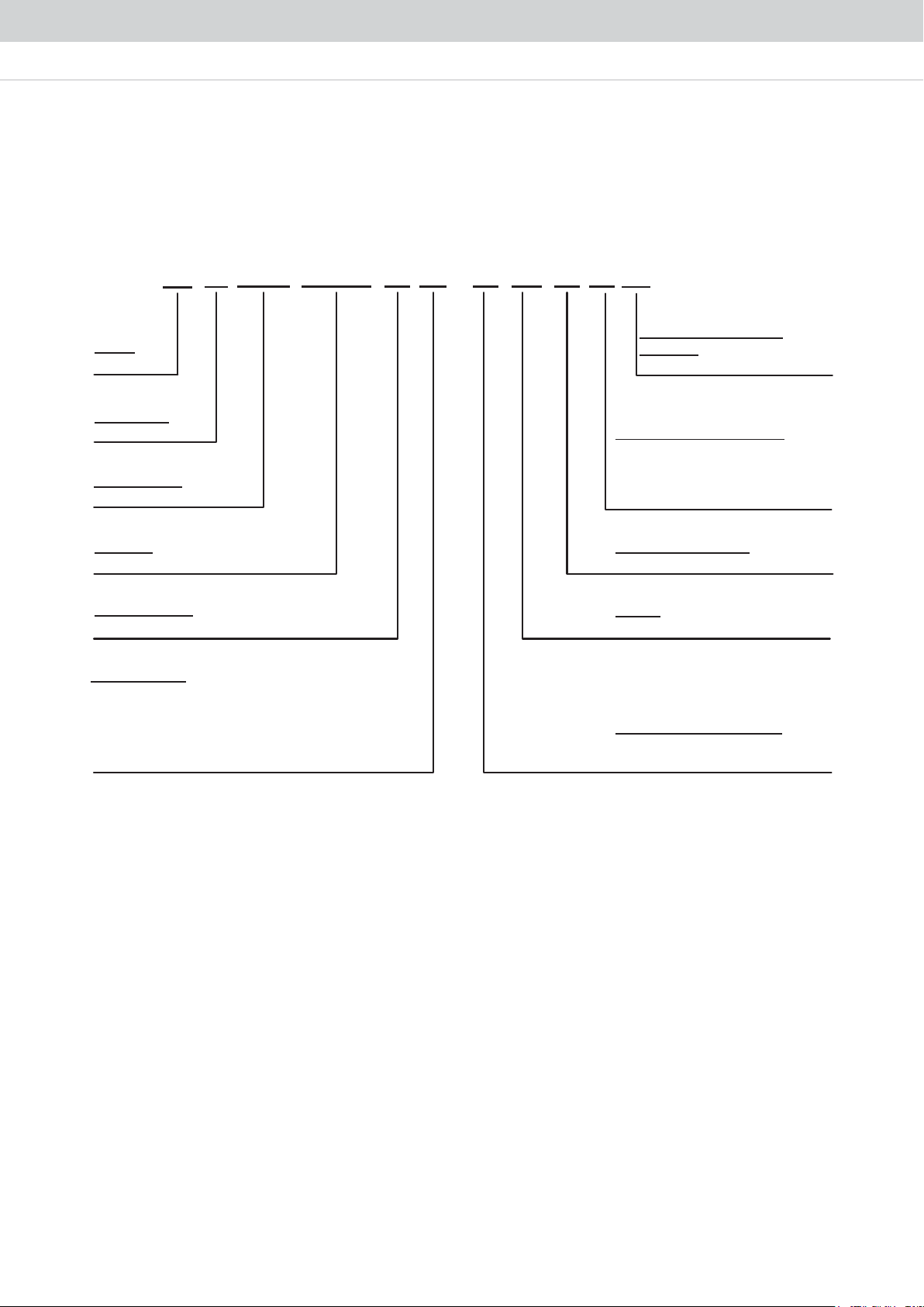
NOMENCLATURE
Indoor
A
Brand
A: Acson
Refrigerant
5: R410A
Product Type
DB: Ducted Blower
Capacity
250: 250,000 Btu/hr
Product Series
H: H series
No. of Circuits
“ ” : 1 Circuit
“2” : 2 Circuits
“3” : 3 Circuits
“4” : 4 Circuits
“5” : 5 Circuits
DB 250 H
5
2
-
F
M
B R
A
Product Specifi cation
Variation
A: Revision
Air Discharge Orientation
H: Horizontal and Not Convertible
N: Horizontal and Convertible
R: Vertical and Convertible
V: Vertical and Not Convertible
Evaporator Fin Type
B: Hydrophilic Blue
Market
M: Malaysia
Electrical Characteristics
A: 1 Phase 50Hz 220-240V
F: 3 Phase 50Hz 380-415V
1
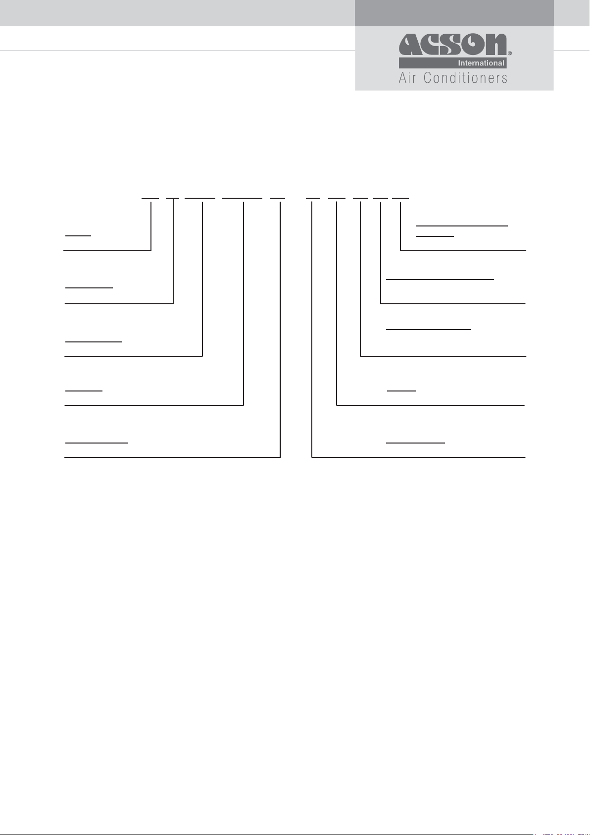
Outdoor
A
5
Brand
A: Acson
Refrigerant
5: R410A
Product Type
MC: Modular Condensing Unit
Capacity
125: 125,000 Btu/hr
Product Series
H: H series
MC 125 H
-
F
M
G R
A
Product Specifi cation
Variation
A: Revision
Air Discharge Orientation
H: Horizontal and Not Convertible
R: Vertical and Convertible
Condenser Fin Type
G: Microchannel
F: E-coating Microchannel
Market
M: Malaysia
Power Supply
Y1: 3 Phase 50Hz 380-415V
2
Product Line-Up
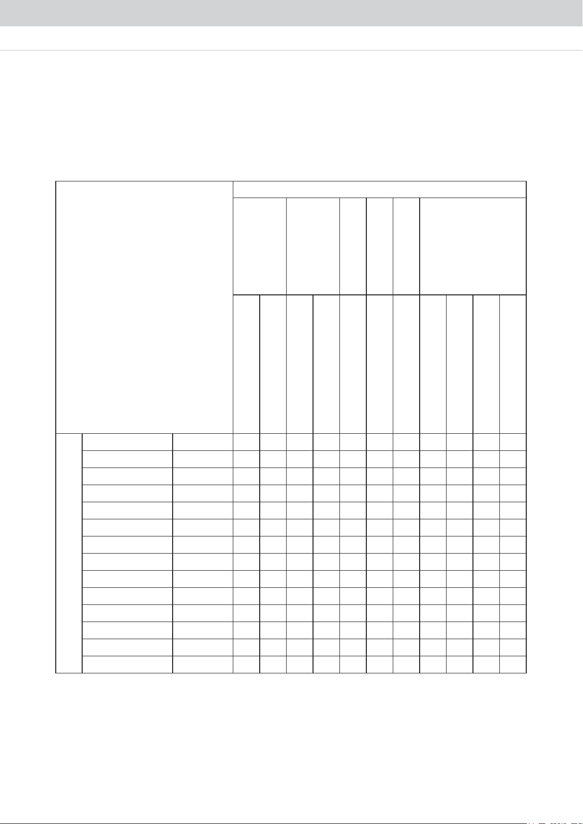
Indoor Unit
A5DB-H
Classifi cation
Control
Nomenclature
W/out Control Module
W/out Contactor
A5DB80H AMBHA X X XXX X X
A5DB100H AMBHA X X XXX X X
A5DB125H FMBNA X X XXXX X
A5DB150H FMBNA X X XXXX X
A5DB200H2 FMBNA X X XXXX X
A5DB250H2 FMBRA X X XXX X X
A5DB300H2 FMBRA X X XXX X X
A5DB300H3 FMBRA X X XXX X X
COOLING
A5DB350B3 FMBRA X X XXX X X
Fin
Bare Aluminium
Hydrophilic Coated
Handset
Refrigerant Control
Air Filter
W/out Handset
TXV
W/out Air Filter
Air Discharge
Horizontal & Convertible
Horizontal & Not Convertible
Vertical & Convertible
Vertical & Not Convertible
A5DB400H4 FMBRA X X XXX X X
A5DB450H3 FMBRA X X XXX X X
A5DB500H4 FMBRA X X XXX X X
XXXXXXXAVBMF4H006BD5A
XXXXXXXAVBMF5H057BD5A
3
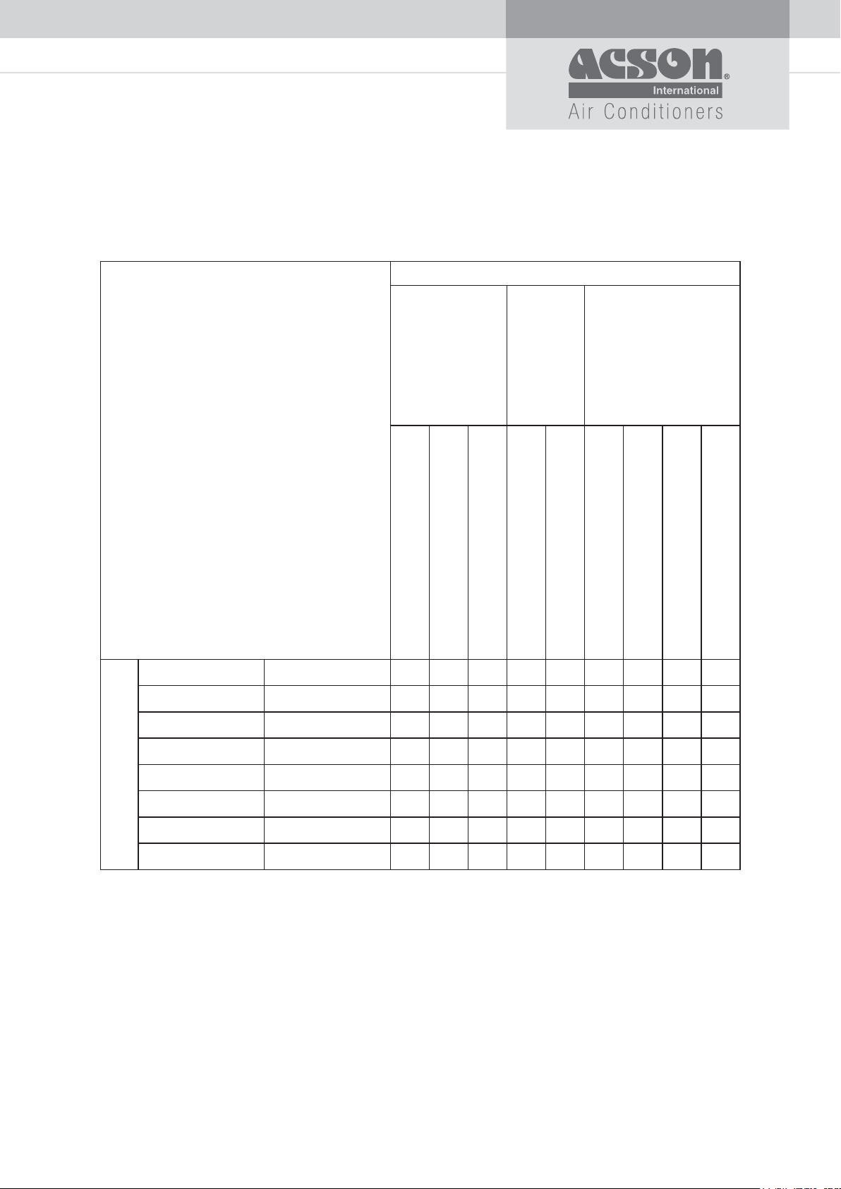
Outdoor Unit
A5MC-H
Classifi cation
Control
Nomenclature
W/out Contactor
With HP/LP Switch/Sensor
With Phase Sequential Protector
A5MC80H FMGHA XXX X X
A5MC80H FMFHA X X X X X
COOLING
A5MC100H FMFRA X X X X X
Fin
Microchannel
E-coating Microchannel
Air Discharge
Horizontal & Convertible
Horizontal & Not Convertible
Vertical & Convertible
Vertical & Not Convertible
XXXXXARGMFH001CM5A
XXXXXARGMFH521CM5A
XXXXXARGMFH051CM5A
A5MC125H FMFRA X X X X X
A5MC150H FMFRA X X X X X
4
APPLICATION INFORMATION
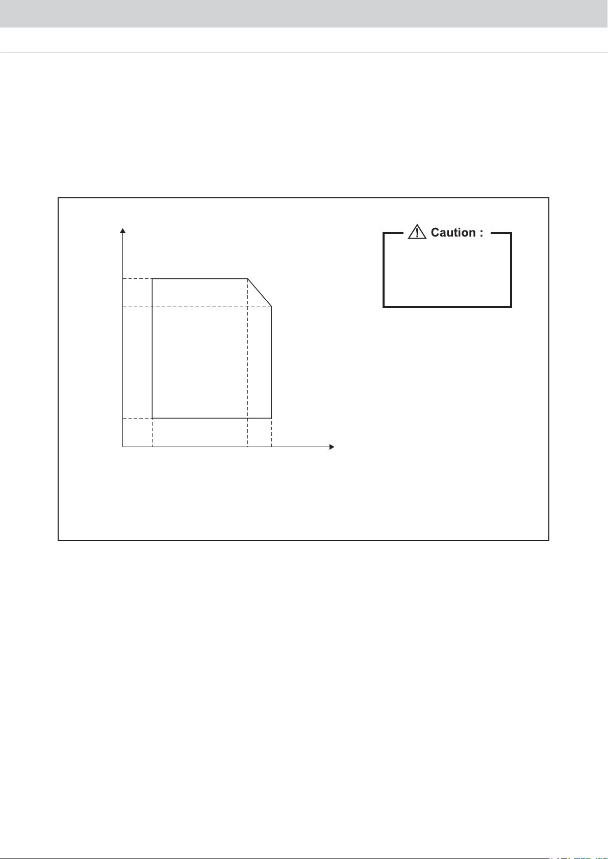
Operating Range
Ensure the operating temperature is in allowance range.
Cooling
Outdoor
DB (°C)
46
43
The use of your air conditioner
outside the range of working
temperature and humidity can
result in serious failure.
19
Cooling Operation Range
DB: Dry Bulb
WB: Wet Bulb
23 )C°( BW roodnI41
5
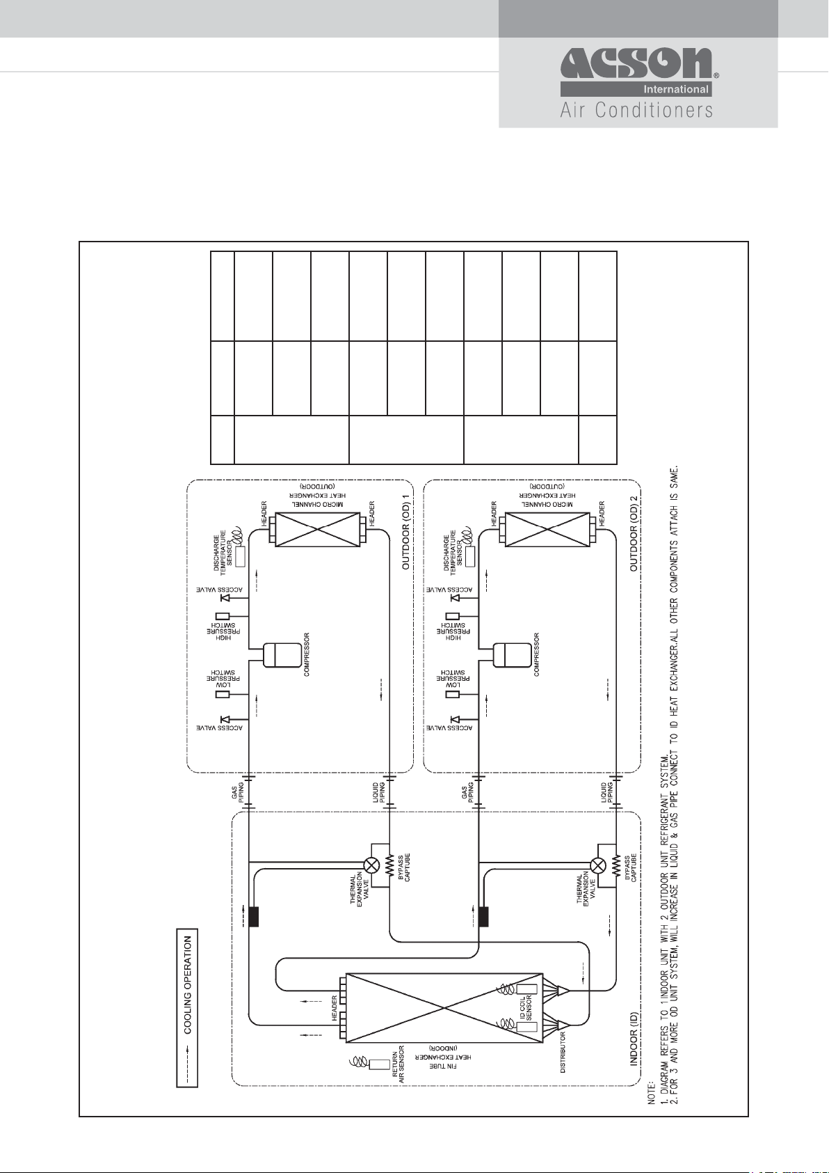
Refrigerant Circuit Diagram
Cooling Only
Outdoor
A5MC100H x 2
Indoor
A5DB200H2
A5MC125H x 2
A5MC150H x 2
A5DB250H2
A5DB300H2
A5MC100H x 3
A5MC100H x 1
A5MC125H x 2
A5DB300H3
A5DB350H3
A5MC150H x 3
A5MC100H x 4
A5DB450H3
A5DB400H4
A5MC125H x 4
A5MC150H x 4
A5DB500H4
A5DB600H4
A5MC150H x 5
A5DB750H5
System
1 IDU
2 ODU
1 IDU
3 ODU
1 IDU
4 ODU
1 IDU
5 ODU
6
Installation Guideline
INDOOR
PRELIMINARY SITE SURVEY
a) Electrical supply and installation is to conform to local authority’s (e.g. National Electricity Board) codes
and regulations.
b) Voltage supply fluctuation must not exceed +/- 10% of rated voltage. Electricity supply line must be
independent of welding transformers which can cause supply fluctuation.
c) Ensure that the location is convenient for wiring and piping.
MOUNTING
a) For ceiling mounted models, locate a position where piping and ducting work can be kept to a minimum.
Ensure that overhead supports are strong enough to hold the unit’s weight. Position hanger rods and
check for alignment with the unit. Check that hangers are secure and that the base of fan-coil unit is level
in two horizontal directions.
DRAINAGE PIPE SIDE
PIPINGS
Do not use contaminated or damaged copper tubings. If pipings, evaporator or condenser are exposed or
had been opened for 15 seconds or more, vacuum and purge with field supplied refrigerant. Generally, do
not remove plastic/rubber plugs/caps from fittings, tubings and coils until ready to connect suction or liquid
line into fittings.
OPERATIONAL CHECK
After all electrical wiring is completed and the system is charged with refrigerant, make sure unit is operating
properly. Check that:
a) Condenser fans are running, with warm air blowing off the condenser coil.
b) Evaporator blowers are running and discharging cool air.
c) Suction line inside condensing unit feels cool.
d) Liquid line inside condensing unit feels warm.
ELECTRICAL CONNECTION
As wiring regulations differ from country to country, please refer to your LOCAL ELECTRICAL CODES for
eld wiring regulations and ensure that these are complied with. Besides, observe the following general
precautions:
a) Ensure that the rated voltage of the unit corresponds to that of the name plate before commencing wiring
work.
b) Provide a power outlet to be used exclusively for each unit. A power supply disconnect and a circuit
breaker for over-current protection should be provided in the exclusive line.
c) The unit must be GROUNDED to prevent possible hazard due to insulation failure.
d) All wiring must be firmly connected.
e) Electrical wiring must not touch the refrigerant piping, compressor and any moving parts of the fan
motors.
7
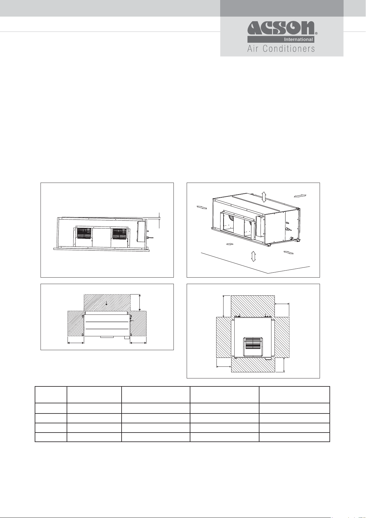
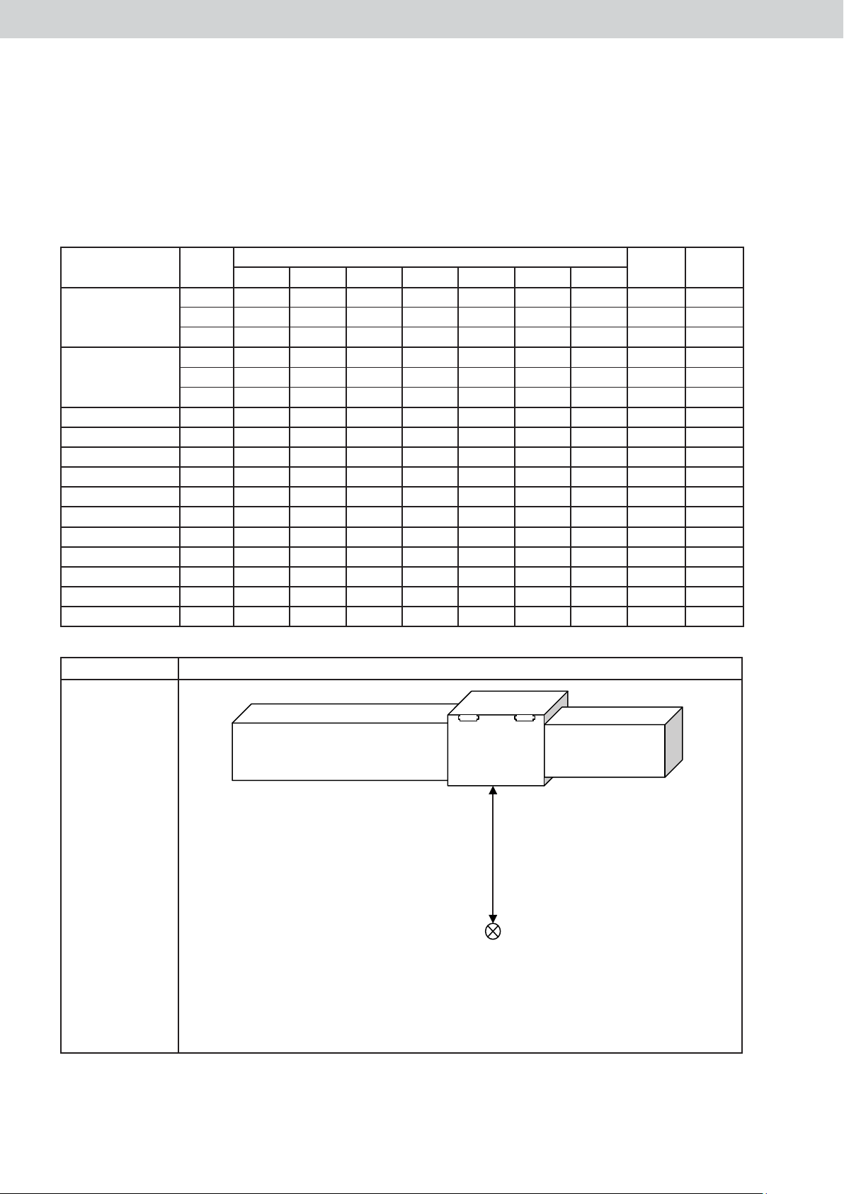
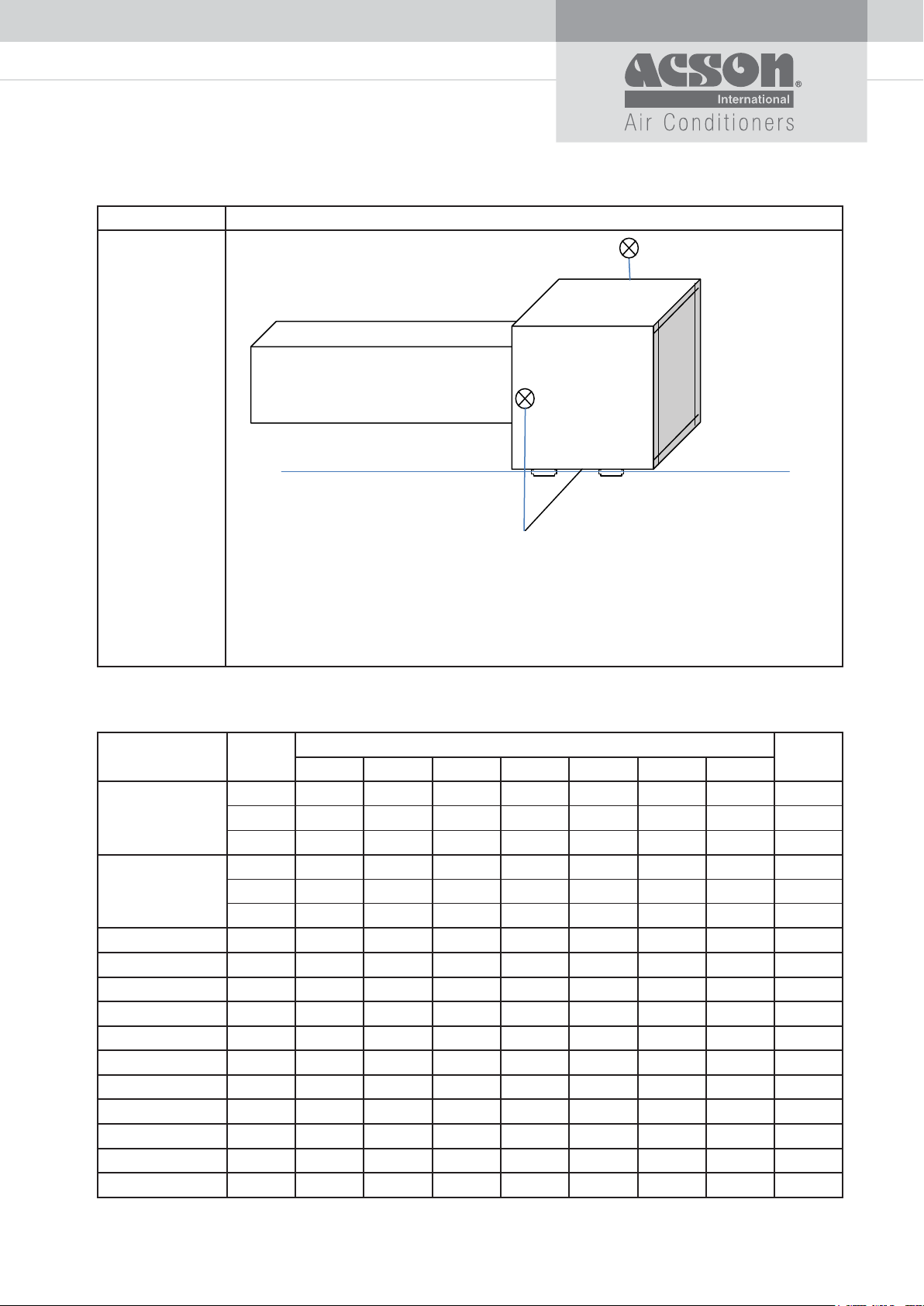
INDOOR CLEARANCE
Mounting
Ensure that the overhead supports are strong enough to hold the unit’s weight. Position hanger rods and
check for alignment with the unit. Check that hangers are secure and that the base of fan-coil unit is level in
the two horizontal directions, taking into account the gradient recommended for drainage flow as shown.
Check the gradient recommended for drainage flow as follow.
Provide clearance for servicing and optimal air flow as shown in the diagram.
The indoor unit must be installed such that there is no short circuit of cool discharge with air discharge.
Respect the installation clearance.
Do not put the indoor unit where there is direct sunlight on unit. The location is suitable for piping and
drainage and it must be have a large distance between a door and unit.
50mm
300mm
10.0
300mm
300mm*
500mm
* for free return of air
Horizontal air discharge
A
All dimensions in mm
B
A
Vertical air discharge
B
A
D
C
Model A5DB80/100H A5DB125/150/200H A5DB250/300/350H A5DB400/450/500H
A5DB600/750H
A (mm) 800 800 800 800
B (mm) 800 800 800 800
008008--)mm( C
D (mm) - - 1000 1500
8
OUTDOOR
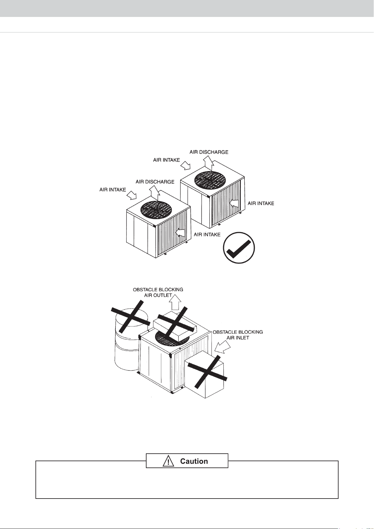
LOCATION FOR INSTALLATION OF THE CONDENSING UNITS
As condensing temperature rises, evaporating temperature rises and cooling capacity drops. In order to
achieve maximum cooling capacity, the location selected should ful fill the following requirements:-
a) Install the condensing (outdoor) unit in a way such that hot air distributed by the outdoor condensing unit
cannot be drawn in again (as in the case of short circuit of hot discharge air). Allow sufficient space for
maintenance around the unit.
b) Ensure that there is no obstruction of air
intake or discharge.
c) The location must be well ventilated, so that the unit can draw and distribute plenty of air thus lowering
the condensing temperature.
d) A place capable of bearing the weight of the outdoor unit and isolating noise and vibration.
e) A place protected from direct sunlight. Otherwise use an awning for protection, if necessary.
f) A place where the hot air discharge and operating sound level will not annoy the neighbours.
g) The location must not be susceptible to dust or oil mist.
flow into or out of the unit. Remove obstacle which block air
If the condensing unit is operated in an atmosphere containing oils (including machine
oils), salt (coastal area), sulphide gas (near hot spring, oil refinery plant), such as
substances may lead to failure of the unit.
9
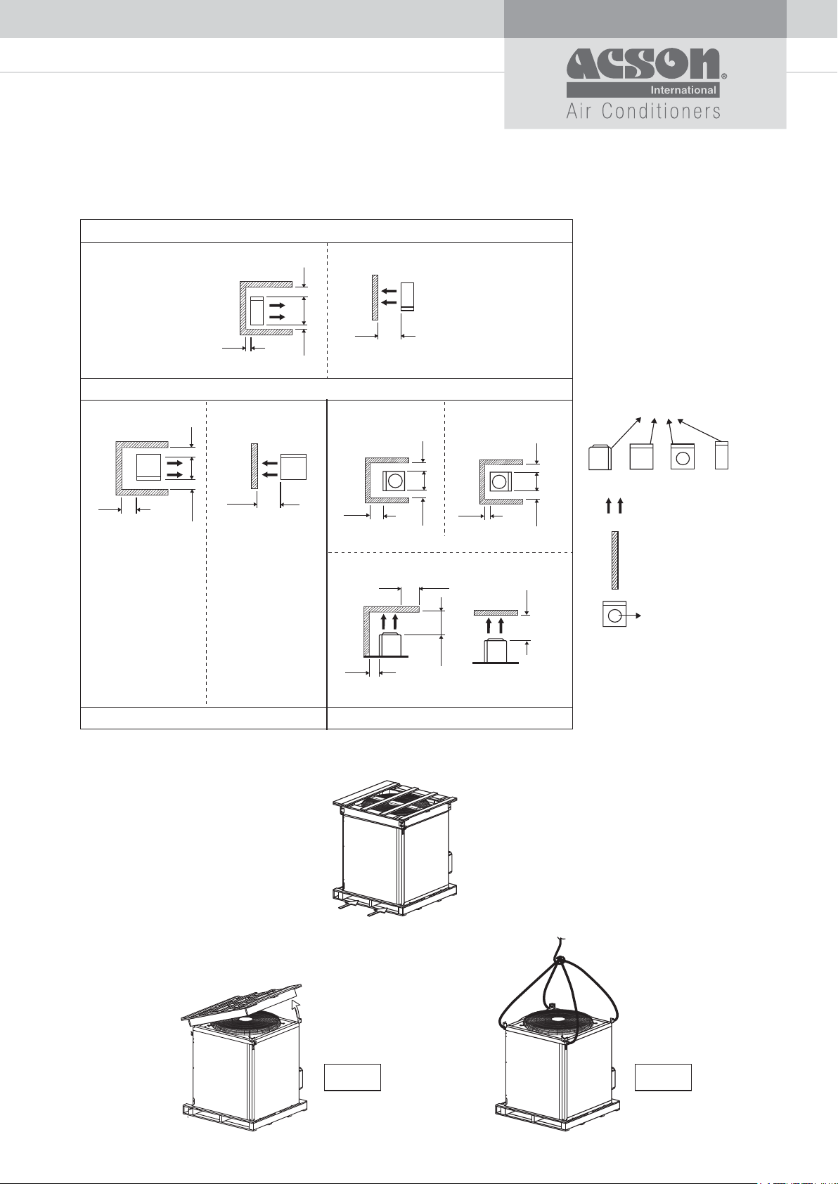
OUTDOOR CLEARANCE
SINGLE UNIT
300
PATTERN 1
300
600
300
1500
PATTERN 1
TOP VIEW
PATTERN 2
TOP VIEWTOP VIEW
300 600
A5MC80H
PATTERN 2
1200
TOP VIEW
PATTERN 1
300100
600
TOP VIEW TOP VIEW
600
SIDE VIEW
300
PATTERN 3
<1500
1500
PATTERN 2
FRONT VIEW
A5MC100/125/150H VERTICAL A5MC100/125/150H HORIZONTAL
1500
100
300
SERVICE PANEL
AIR DISCHARGE
DIRECTION
WALL / CEILING
AIR DISCHARGE GRILL
NOTE :
1) ALL DIMENSION ARE IN MM.
2) ALL DIMENSION MENTIONED ARE
MINIMUM DISTANCE REQUIRED.
UNLESS OTHERWISE SPECIFIED.
Unit Lifting
a) By pallet truck / fork lift
b) By crane
LEFT BY PALLET TRUCK/FOKLIFT
LEFT BY CRANE USING BELT
CONNECT TO 4 CORNER HOIST BRACKET
REMOVE THE TOP CRATE
Step 1 Step 2
10
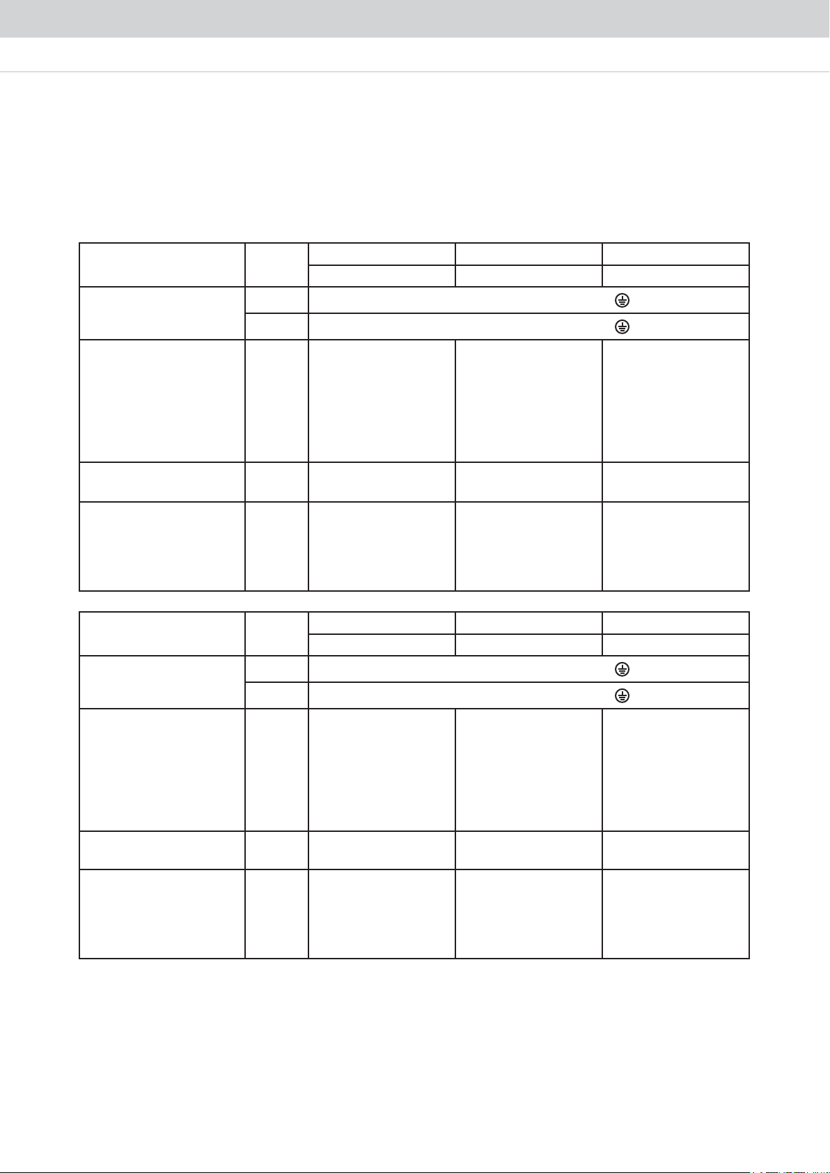
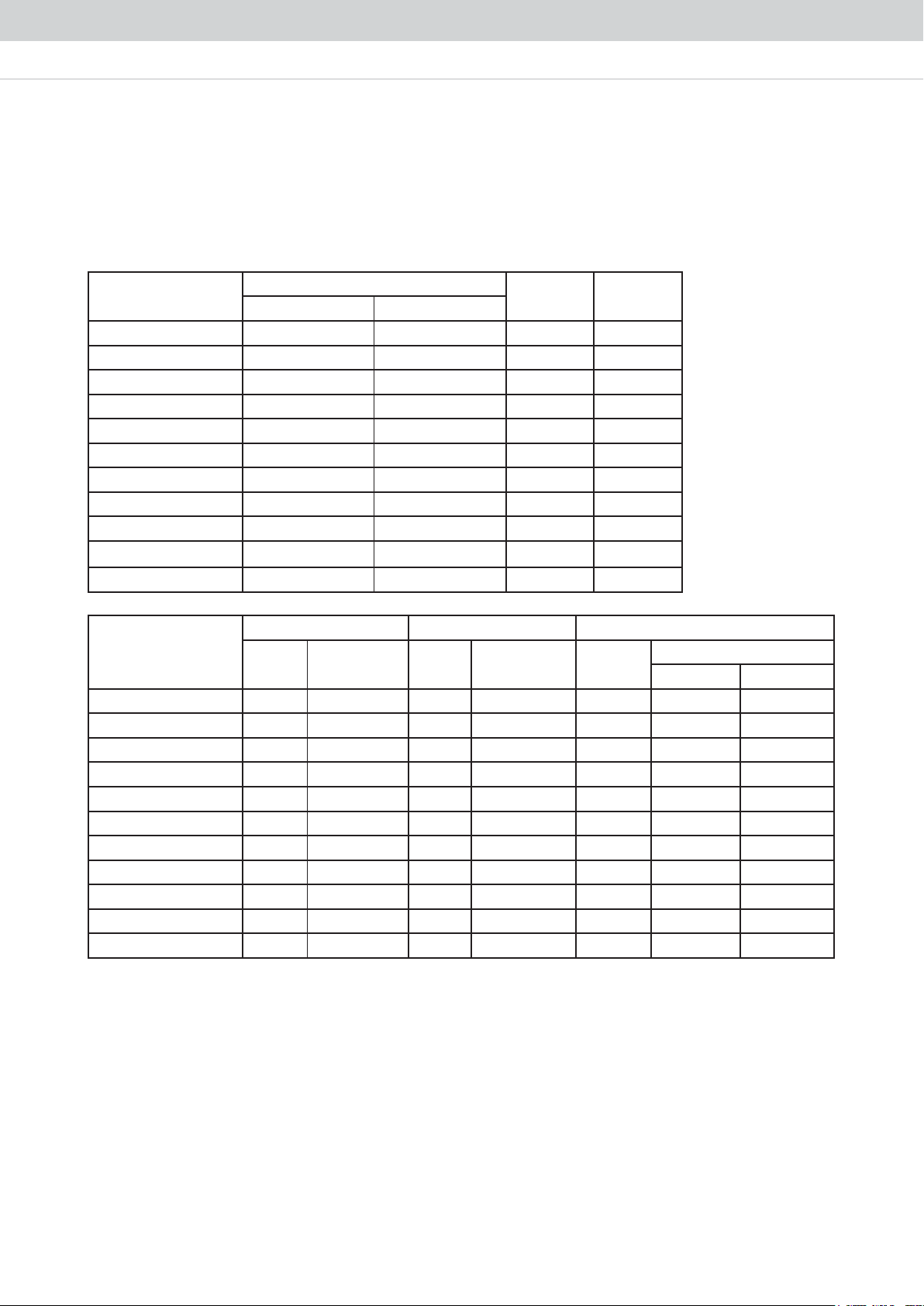
CABLE SIZE
Cooling only
Model Unit
Voltage range**
Power supply cable size*
a) Indoor Unit
b) Outdoor Unit
c) Total
Number of conductors
a) Indoor Unit
b) Outdoor Unit
Interconnection cable size*
Number of conductors
Recommended fuse/
circuit breaker rating*
a) Indoor Unit
b) Outdoor Unit
c) Total
Model Unit
Voltage range**
Power supply cable size*
a) Indoor Unit
b) Outdoor Unit
c) Total
Number of conductors
a) Indoor Unit
b) Outdoor Unit
Interconnection cable size*
Number of conductors
Recommended fuse/
circuit breaker rating*
a) Indoor Unit
b) Outdoor Unit
c) Total
Indoor
Outdoor
2
mm
2
mm
2
mm
2
mm
A
A
A
Indoor
Outdoor
2
mm
2
mm
2
mm
2
mm
A
A
A
A5DB80H A5DB100H A5DB125H
A5MC80H A5MC100H A5MC125H
380 - 415V / 3Ph /50Hz + N +
380 - 415V / 3Ph /50Hz + N +
1.0
2.5
2.5
-
5
1
4
6
32
32
1.0
2.5
2.5
-
5
1
4
16
32
40
1.0
2.5
2.5
5
5
-
-
4
40
40
A5DB150H A5DB200H2 A5DB250H2
A5MC150H
A5MC100H x 2 A5MC125H x 2
380 - 415V / 3Ph /50Hz + N +
380 - 415V / 3Ph /50Hz + N +
1.0
4.0
4.0
5
5
-
-
6
50
50
1.0
2.5
6.0
5
5
-
-
10
32
50
1.0
2.5
10.0
5
5
-
-
16
40
63
11
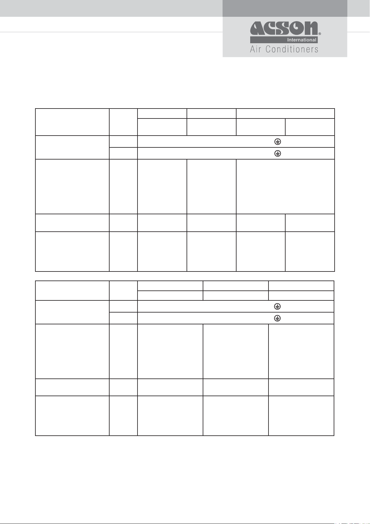
Model Unit
Voltage range**
Power supply cable size*
a) Indoor Unit
b) Outdoor Unit
c) Total
Number of conductors
a) Indoor Unit
b) Outdoor Unit
Interconnection cable size*
Number of conductors
Recommended fuse/
circuit breaker rating*
a) Indoor Unit
b) Outdoor Unit
c) Total
Indoor
Outdoor
2
mm
2
mm
2
mm
2
mm
A
A
A
A5DB300H2 A5DB300H3 A5DB350H3
A5MC150H
x 2
A5MC100H
x 3
A5MC100H
380 - 415V / 3Ph /50Hz + N +
A5MC125H
380 - 415V / 3Ph /50Hz + N +
1.0
4.0
16.0
5
5
-
-
16
50
80
1.0
2.5
16.0
5
5
-
-
16
40
63
1.0
2.5
16.0
5
5
-
-
16
32
80
x 2
-
-
16
40
80
Model Unit
Voltage range**
Power supply cable size*
a) Indoor Unit
b) Outdoor Unit
c) Total
Number of conductors
a) Indoor Unit
b) Outdoor Unit
Interconnection cable size*
Number of conductors
Recommended fuse/
circuit breaker rating*
a) Indoor Unit
b) Outdoor Unit
c) Total
Indoor
Outdoor
2
mm
2
mm
2
mm
2
mm
A
A
A
A5DB400H4 A5DB450H3 A5DB500H4
A5MC100H x 4
380 - 415V / 3Ph /50Hz + N +
A5MC150H x 3 A5MC125H x 4
380 - 415V / 3Ph /50Hz + N +
1.0
2.5
25.0
5
5
-
-
20
32
80
1.0
4.0
25.0
5
5
-
-
20
50
100
2.5
2.5
25.0
5
5
-
-
32
40
100
12
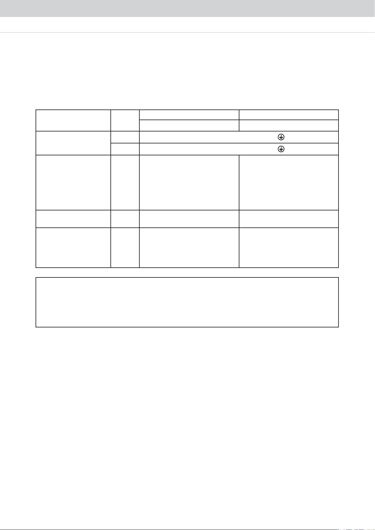
Model Unit
Voltage range**
Indoor
Outdoor
A5MC150H x 4 A5MC150H x 5
380 - 415V / 3Ph /50Hz + N +
380 - 415V / 3Ph /50Hz + N +
Power supply cable size*
a) Indoor Unit
b) Outdoor Unit
c) Total
mm
mm
mm
2
2
2
2.5
4.0
35.0
2.5
4.0
50.0
Number of conductors
a) Indoor Unit
b) Outdoor Unit
Interconnection cable size*
Number of conductors
mm
5
5
2
-
-
5
5
-
-
Recommended fuse/
circuit breaker rating*
a) Indoor Unit
b) Outdoor Unit
c) Total
A
A
A
32
50
125
50
50
175
IMPORTANT:
* These values are for information only. They should be checked and selected to
comply with local and/or national codes and regulations.
They are also subject to the type of installation and size of conductors.
** The appropriate voltage range should be checked with label data on the unit.
5H057BD5A4H006BD5A
13
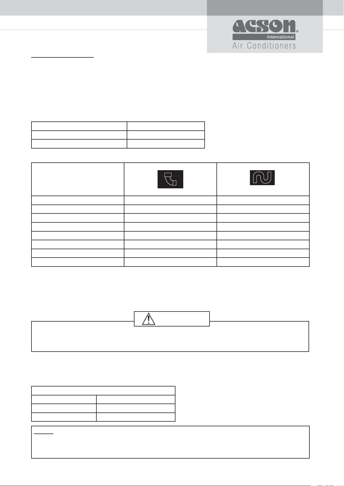
REFRIGERANT PIPING
Maximum Piping Length and Maximum Number of Bends
When the pipe length becomes too long, both the capacity and reliability will drop and as the number of
bends increases, system piping resistance to the refrigerant flow increases, thus lowering the cooling
capacity. As a result the compressor may become defective. Always choose the shortest path and follow the
recommendation as tabulated below:
Cooling Only Model
Outdoor A5MC80/100/125/150H
Maximum Allowable Length, m 75
Maximum Allowable Elevation, m 30
Equivalent length for various fitting (meter)
tnioj LeziS epiP Trap bend
03.181.0)mm25.9 DO( ”8/3
05.102.0 )mm07.21 DO( ”2/1
00.252.0)mm88.51 DO( ”8/5
01.253.0 )mm50.91 DO( ”4/3
00.304.0 )mm32.22 DO( ”8/7
04.354.0 )mm04.52 DO( ”1
07.305.0 )mm85.82 DO( ”8/1 1
04.406.0 )mm29.43 DO( ”8/3 1
Notes:
1. Equivalent piping length is obtained with actual length of gas piping.
2. 90° bend of piping is equivalent to L joint.
Bending must be carefully made so as not to crush the pipe.
Use a pipe bender to bend a pipe where possible.
CAUTION
Our guarantee on the performance of our air-conditioners is strictly revoked if the height
and/or length of the refrigerant piping system installed is beyond the limit above.
Additional Charge
For Brazed type, if the piping is less than 7.5m, follow the charge level on serial number sticker. When the
piping is more than 7.5m, use the table below.
R410A
Liquid Pipe OD (in) Additional Charge (kg/m)
80.0’’2/1
41.0’’8/5
NOTE:
The additional refrigerant charge amount recommended is a guideline for long piping
application. The actual charge required may be different from the guideline due to different
application and variation in site condition.
14
SOUND DATA
SOUND PRESSURE LEVEL
Indoor
Model Speed
High 57 48 50 45 46 40 29 52 47
A5DB80H
A5DB100H
A5DB125H High 53 52 53 46 43 39 28 53 49
A5DB150H High 54 54 56 48 45 41 32 56 53
A5DB200H2 High 58 60 60 55 54 48 42 61 57
A5DB250H2 High 62 57 59 59 57 52 43 63 58
A5DB300H2/H3 High 66 60 62 61 59 54 44 66 60
A5DB350H3 High 67 60 62 62 59 54 44 66 61
A5DB400H4 High 67 64 63 63 59 54 45 66 62
A5DB450H3 High 68 64 65 63 60 55 46 68 62
A5DB500H4 High 69 66 66 64 61 56 47 68 63
A5DB600H4 High 70 68 68 66 62 57 48 70 65
A5DB750H5 High 71 69 69 67 63 57 48 71 66
Med 55 48 51 45 46 39 28 52 47
Low 60 47 50 44 45 38 27 52 46
High 64 54 52 48 48 42 34 55 50
Med 64 53 51 47 48 42 33 54 50
Low 64 52 50 45 48 41 32 54 50
125Hz 250Hz 500Hz 1kHz 2kHz 4kHz 8kHz
1/1 Octave Sound Pressure (dB, ref 20μPa)
Overall
(dBA)
Criteria
Noise
A5DB80H
A5DB100H
A5DB125H
A5DB150H
A5DB200H2
noitacoL gnirusaeM ledoM roodnI
2m discharge duct length
UNIT
1.5m
1m return duct length
Microphone position:
1.5m below centre of the unit.
(Tested with 2m length duct at the air discharge outlet and 1m length air return inlet)
Standard: JIS B 8615
15
A5DB250H2
A5DB300H2/H3
A5DB350H3
A5DB400H4
A5DB450H3
A5DB500H4
A5DB600H4
A5DB750H5
noitacoL gnirusaeM ledoM roodnI
UNIT
2m discharge duct length
1m
1m
Microphone position:
1m away from every side panel of the unit and 1m above the fl oor level.
(Tested with 2m length duct at the air discharge outlet only)
Standard: JIS B 8615
Free return duct
Sound Power Level
Model Speed
*A5DB80H
*A5DB100H
High
Med
Low
High
Med
Low
125Hz 250Hz 500Hz 1kHz 2kHz 4kHz 8kHz
68 67 70 69 64 62 54 73
69 64 68 68 61 59 60 70
66 62 66 63 58 56 46 67
74 72 74 73 66 65 59 77
73 70 73 71 64 62 55 75
70 68 71 68 60 59 49 72
1/1 Octave Sound Power Level (dB) ref 1pW
*A5DB125H High 75 76 78 70 69 62 58 78
*A5DB150H High 74 77 78 75 72 69 63 80
*A5DB200H2 High 83 84 83 81 77 73 68 85
A5DB250H2 High 85 86 85 83 79 75 70 87
A5DB300H2/H3 High 87 88 87 85 81 77 72 89
A5DB350H3 High 90 91 90 87 84 80 75 92
A5DB400H4 High 88 89 88 86 82 78 73 90
A5DB450H3 High 91 92 91 89 85 81 76 93
A5DB500H4 High 94 95 94 92 88 84 79 96
A5DB600H4 High 87 88 87 85 81 77 72 89
A5DB750H5 High 91 92 91 89 85 81 76 93
Overall
(dBA)
*Remarks: Test with 5ft length discharge duct, terminated flush with the internal wall of reverberation room.
16
NC Curve
80
A5DB80H
70
Pa)
μ
60
H
M
L
50
40
30
Sound pressure level (dB, ref 20
20
10
NC70
NC65
NC60
NC55
NC50
NC45
NC40
NC35
NC30
NC25
NC20
0008000400020001005052521
Octave-band frequency (Hz)
A5DB100H
17
Sound pressure level (dB, ref 20μPa)
80
70
60
NC70
NC65
NC60
50
40
H
M
L
NC55
NC50
NC45
NC40
30
NC35
NC30
20
NC25
NC20
10
0008000400020001005052521
Octave-band frequency (Hz)
A5DB125H
80
Sound pressure level (dB, ref 20μPa)
70
60
NC70
NC65
NC60
50
40
H
NC55
NC50
NC45
NC40
30
NC35
NC30
20
NC25
NC20
10
0008000400020001005052521
Octave-band frequency (Hz)
A5DB150H
80
70
μPa)
60
50
40
30
Sound pressure level (dB, ref 20
20
10
H
Octave-band frequency (Hz)
NC70
NC65
NC60
NC55
NC50
NC45
NC40
NC35
NC30
NC25
NC20
0008000400020001005052521
18
A5DB200H2
80
Sound pressure level (dB, ref 20μPa)
70
70
60
H
50
40
30
20
10
NC70
NC65
NC60
NC55
NC50
NC45
NC40
NC35
NC30
NC25
NC20
0008000400020001005052521
Octave-band frequency (Hz)
A5DB250H2
19
60
H
NC-55
50
NC-50
NC-45
40
NC-40
NC-35
30
NC-30
NC-25
20
Sound pressure level (dB, ref 20μPa)
10
0
125 250 500 1000 2000 4000 8000
NC-20
Octave-band frequency (Hz)

A5DB300H2
70
60
NC-55
50
40
30
20
Sound pressure level (dB, ref 20μPa)
10
0
125 250 500 1000 2000 4000 8000
NC-50
NC-45
NC-40
NC-35
NC-30
NC-25
NC-20
Octave-band frequency (Hz)
H
A5DB300H3
70
60
50
40
30
20
10
Sound pressure level (dB, ref 20μPa)
0
125 250 500 1000 2000 4000 8000
H
NC-45
NC-35
Octave-band frequency (Hz)
NC-55
NC-50
NC-40
NC-30
NC-25
NC-20
20
A5DB350H3
70
H
60
NC-55
50
40
30
20
Sound pressure level (dB, ref 20μPa)
10
0
125 250 500 1000 2000 4000 8000
Octave-band frequency (Hz)
NC-50
NC-45
NC-40
NC-35
NC-30
NC-25
NC-20
21
A5DB400H4
70
H
60
NC-55
50
40
30
20
Sound pressure level (dB, ref 20μPa)
10
0
125 250 500 1000 2000 4000 8000
Octave-band frequency (Hz)
NC-50
NC-45
NC-40
NC-35
NC-30
NC-25
NC-20
A5DB450H3
70
H
60
NC-55
50
40
30
20
Sound pressure level (dB, ref 20μPa)
10
0
125 250 500 1000 2000 4000 8000
Octave-band frequency (Hz)
NC-50
NC-45
NC-40
NC-35
NC-30
NC-25
NC-20
A5DB500H4
70
60
50
40
30
20
Sound pressure level (dB, ref 20μPa)
10
0
125 250 500 1000 2000 4000 8000
H
Octave-band frequency (Hz)
NC-55
NC-50
NC-45
NC-40
NC-35
NC-30
NC-25
NC-20
22
A5DB600H4
70
H
60
NC-55
50
40
30
20
Sound pressure level (dB, ref 20μPa)
10
0
125 250 500 1000 2000 4000 8000
Octave-band frequency (Hz)
NC-50
NC-45
NC-40
NC-35
NC-30
NC-25
NC-20
A5DB750H5
90
80
70
60
50
40
30
20
Sound Pressure Level (dB, ref 20
10
0
125 250 500 1000 2000 4000 8000
H
NC-50
Octave-band Freque ncy (Hz)
NC-70
NC-65
NC-60
NC-55
NC-45
NC-40
NC-35
NC-30
NC-25
NC-20
23

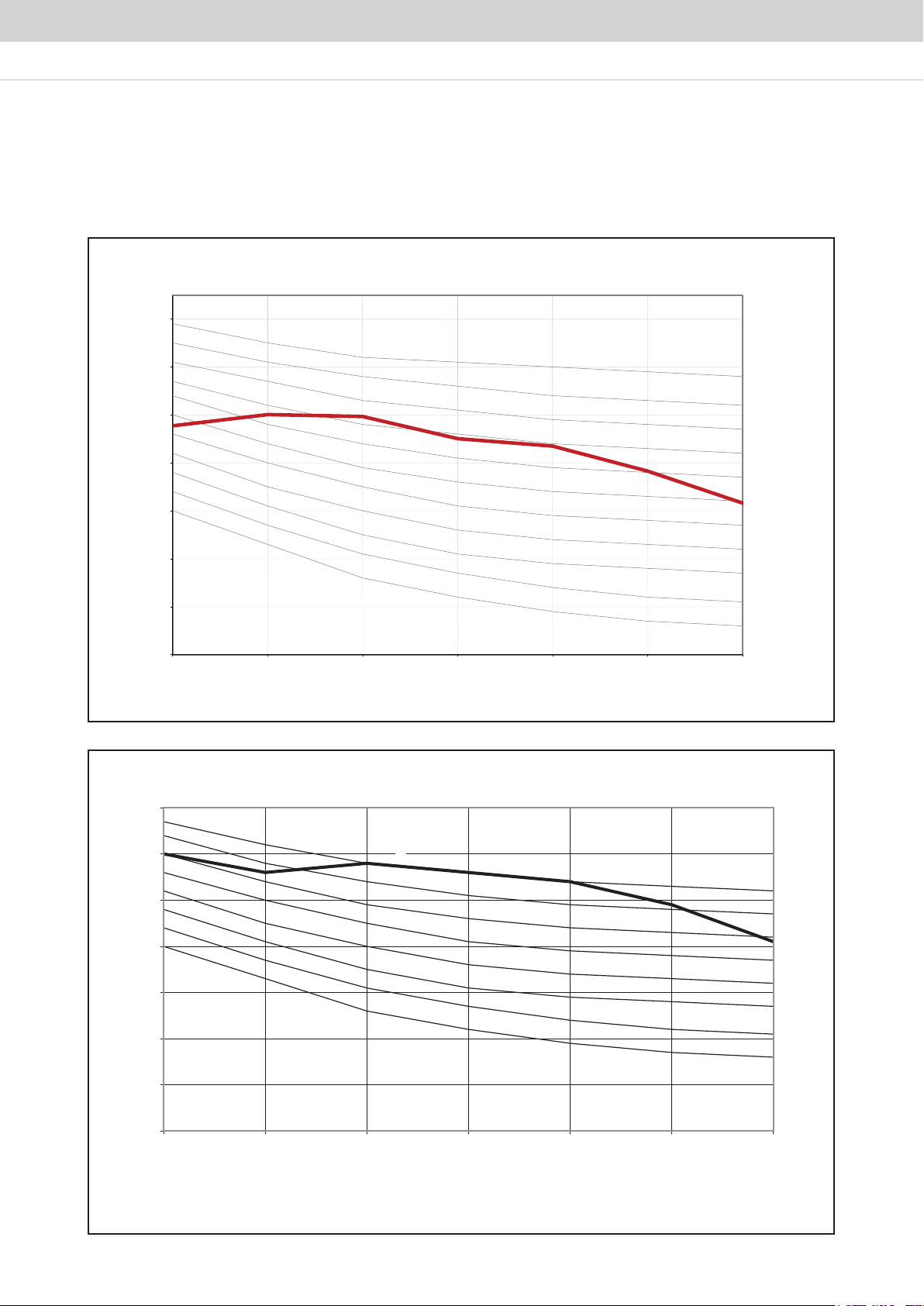
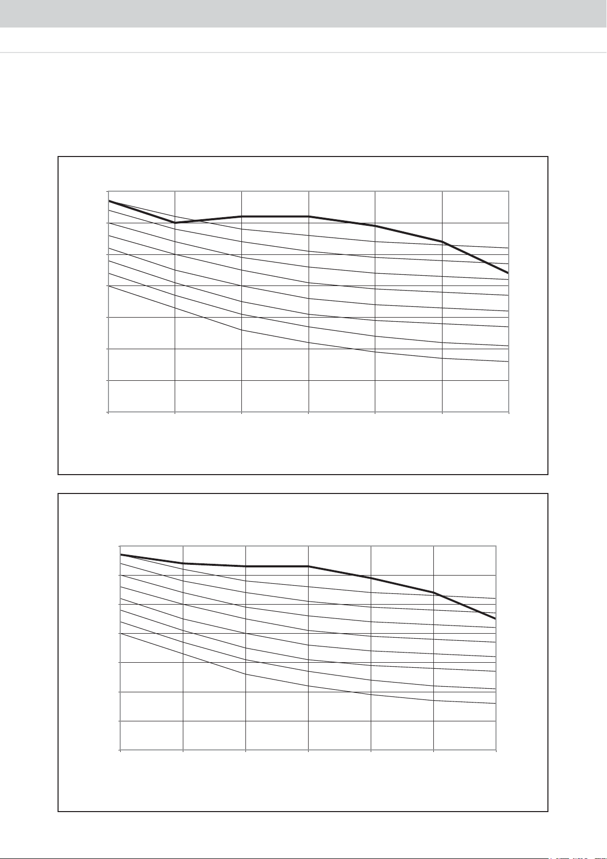
SELECTION PROCESS
Fan Performance Chart
Example 1 :
The following are the design requirements for A5DB250H2 unit:
Model: A5DB250H2
Supply Air Quantity = 9000 CFM
External Static Pressure = 350 Pa
Step 1: From the fan curve (at 9000 CFM),
Standard operating system;
Total Static Pressure = 410 Pa
Internal Static Pressure, ISP = 110 Pa
External Static Pressure, ESP = 300 Pa
External Static Pressure of 300 Pa did not fulfil the design requirements.
Step 2: Therefore at 9000 CFM and 350 Pa external static pressure,
Total Static Pressure = ISP + ESP Pa
= 140 + 350 Pa
= 490 Pa
Step 3: From the fan curve, the design requirement calls for RPM about 810, whereas the unit can only deliver
RPM about 715 under the same CFM. Therefore, it is necessary to RPM about 810 under the same CFM.
Therefore, it is necessary to resize the pulley sizes.
From the table:
Motor pulley = 90 mm
Blower pulley = 200 mm
Motor RPM = 1440
In order to obtain 810 RPM, we recalculate the new blower pulley as:
(while maintaining the motor pulley)
)018/0441( x 09 = bD
mm 0.061 =
The nearest pulley size will be a diameter of 160mm
Recheck, with Db = 160mm
Blower pulley = 1440 x (90/160)
= 810
We thus need to change the blower pulley from 200mm to 160mm in order to obtain the higher operating
static pressure.
Step 4: When the pulley is changed, the V-belt length must be rechecked. We have for horizontal air throw
con guration:
V-belt length, L = 2C + 1.57 (Db + Dm) + (Db - Dm)2 / 4C
99.1 + )09 + 061( 75.1 + )516 x 2( =
mm94.4261 =
We thus can use a belt with a length of 1637mm
where, C = distance between the centres of the two pulleys
Db = diameter of blower pulley
Dm = diameter of motor pulley
Step 5: From the fan curve, we can also notice that the motor power input has increased, which is now higher than
the standard 4.0 kW. At the new operating point, the power is approximately 4.2 kW.
Thus, the existing motor is not sufficient to drive the blower with the smaller 180mm pulley.
Summary:
i) Fan motor kW = 5.5 kW
ii) Blower pulley diameter = 160 mm
iii) V-belt size = 1637 mm
24
The following table summarizes the pulley data, motor size used for the A5DB-H series, as manufactured:
Model
A5DB125H 265 240 1.5 1500
A5DB150H 265 260 1.5 1500
A5DB200H2 360 325 3.0 1420
A5DB250H2 620 615 4.0 1440
A5DB300H2/H3 635 610 4.0 1440
A5DB350H3 870 850 5.5 1440
A5DB400H4 805 750 5.5 1440
A5DB450H3 795 745 7.5 1440
A5DB500H4 770 725 11.0 1460
A5DB600H4 515 335 11.0 1460
A5DB750H5 510 330 15.0 1460
Model
A5DB125H SPZ 85 / 1210 SPZ 180 / 1610 SPZ 900 1060
A5DB150H SPZ 71 / 1108 SPZ 140 / 1610 SPZ 800 962
A5DB200H2 SPZ 75 / 1210 SPZ 2 140 / 1610 SPZ 1010 1060
A5DB250H2 SPZ 2 90 / 1610 SPZ 2 180 / 2012 SPZ 1700 1700
A5DB300H2/H3 SPZ 2 95 / 1610 SPZ 2 180 / 2012 SPZ 1650 1700
A5DB350H3 SPZ 2 85 / 1610 SPZ 2 150 / 2012 SPZ 2060 2120
A5DB400H4 SPA 2 100 / 1610 SPA 2 250 / 2517 SPA 2060 2160
A5DB450H3 SPA 2 112 / 1610 SPA 2 250 / 2517 SPA 2060 2160
A5DB500H4 SPA 3 125 / 2012 SPA 3 250 / 2517 SPA 2032 2132
A5DB600H4 SPA 3 125 / 2012 SPA 3 400 / 3020 SPA 1532 1850
A5DB750H5 SPA 3 132 / 2012 SPA 3 400 / 3020 SPA 1500 1850
Pulley Centre Distance, C
Horizontal (mm) Vertical (mm)
Motor Pulley, Dm Blower Pulley, Db V-Belt
Type
Diameter
(mm)
Type
Motor
(kW)
Diameter
(mm)
Motor
Type
RPM
Length (mm)
Horizontal Vertical
25
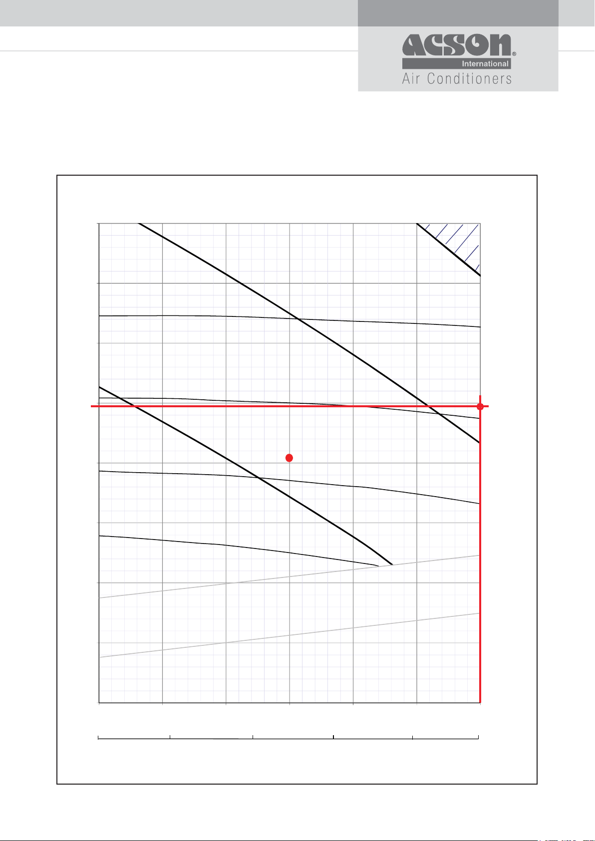
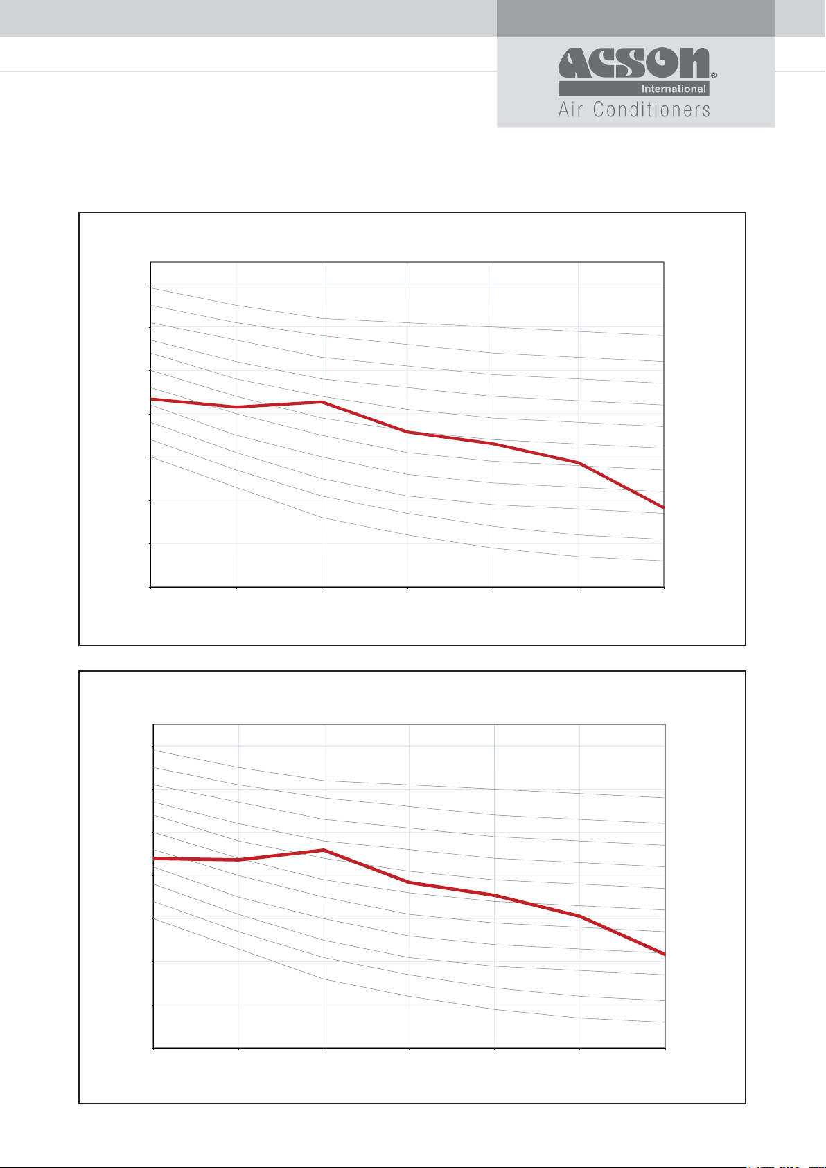
Example 1:
A5DB250H2 Blower Curve
800
700
4.0 kW
5.5 kW
RPM
900
600
Selected
500
490
3.0 kW
Point
800
Standard
Point
400
700
Total Static Pressure (Pa)
300
200
100
0
6000 6500 7000 7500 8000 8500 9000
2830
3100
3300
3700
600
Internal Static
Pressure with
filter
Internal Static
Pressure w/o
filter
4100
Air Flow
9000
4250
CFM
L/s
26
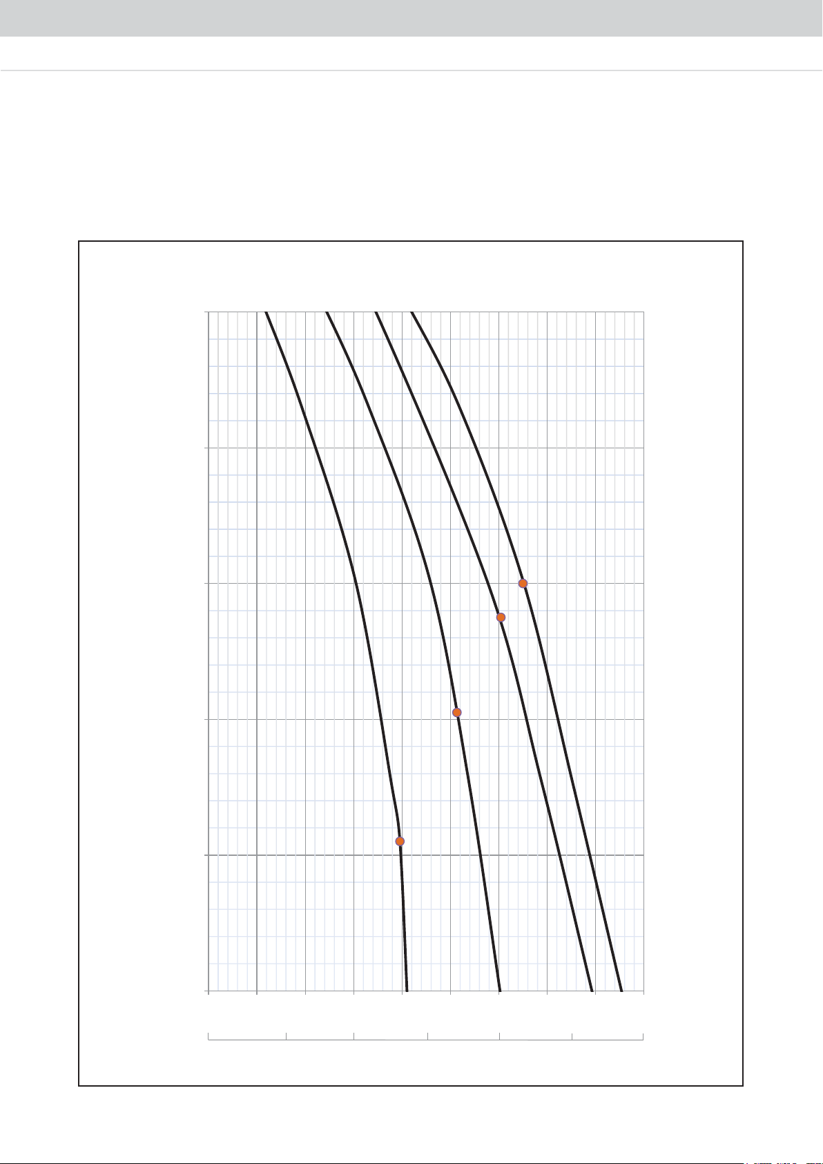
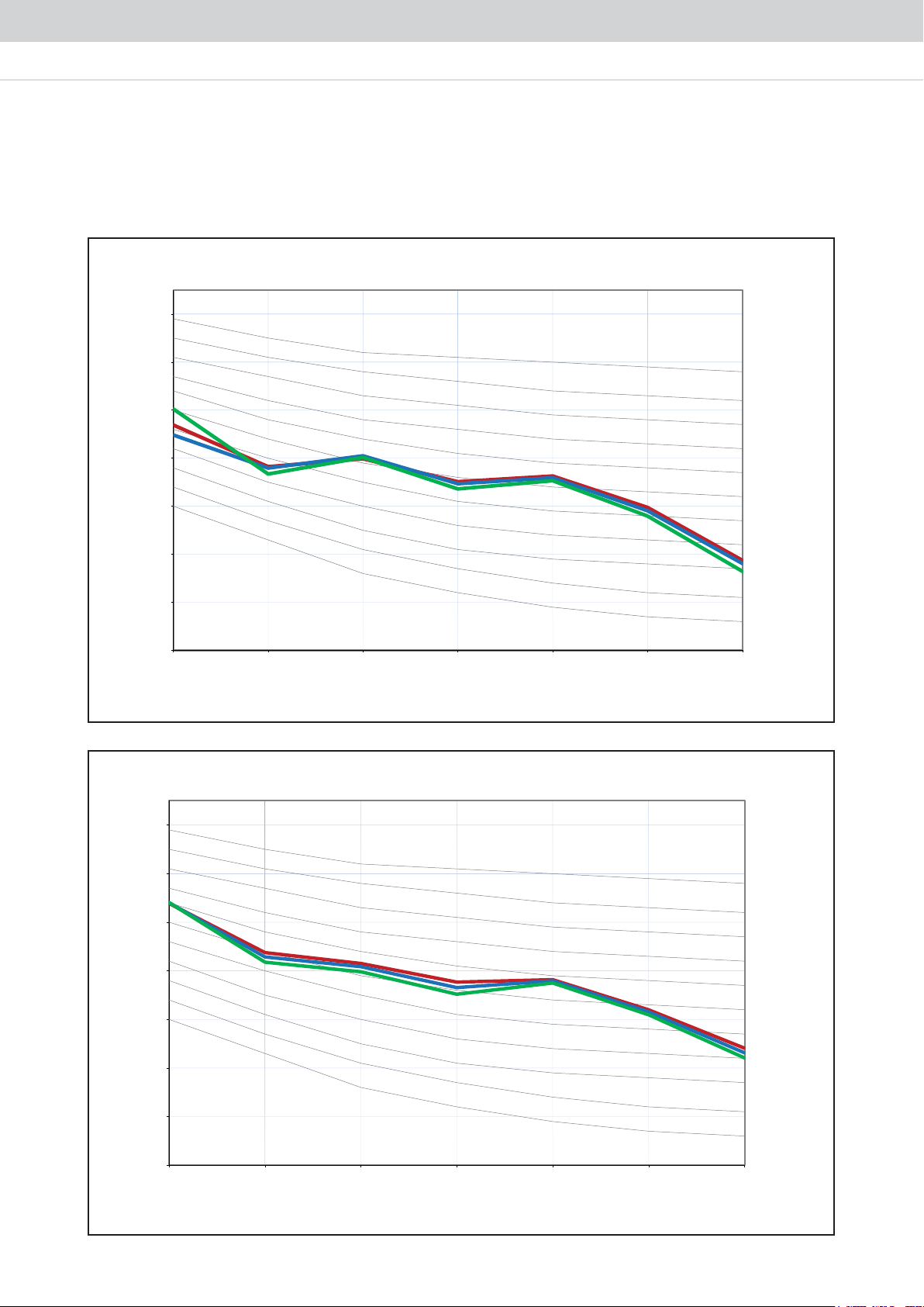
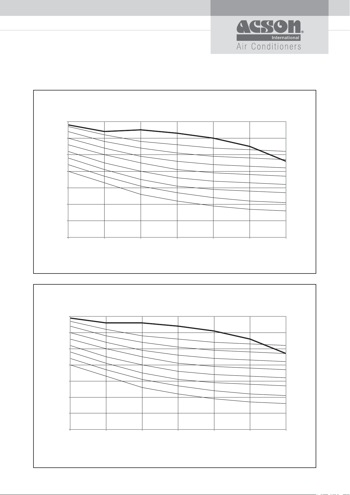
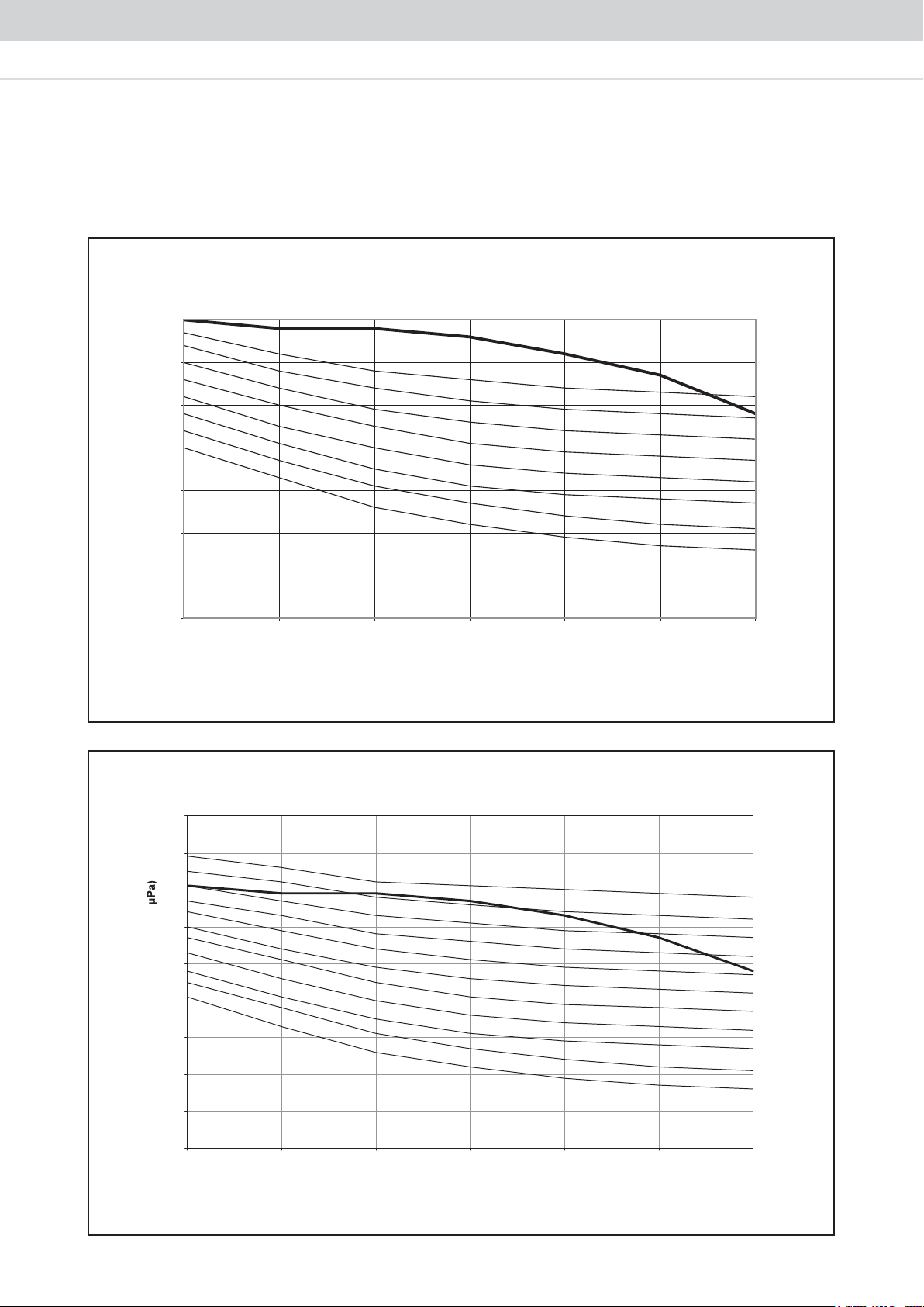
FAN PERFORMANCE CURVE
760
900
1320
1040
1180
SUPER HIGH
140
LOW
120
100
A5DB80H (with filter)
MEDIUM
SUPER HIGH
HIGH
27
80
External Static Pressure (Pa)
60
40
1000 1200 1400 1600 1800 2000 2200 2400 2600 2800
470
620
CFM
L/s
Air Flow
 Loading...