

Page 1
Technical Manual
AIR-COOLED
MINI CHILLER
AMAC 20-150 C/CR
A4AC 20-150 C
A4AC 60-150 CR
A5AC 20-55 CR
Page 2

1. NOMENCLATURE .................................................................................................. 1
- PRODUCT LINE UP
2. FEATURES ............................................................................................................. 5
3. APPLICATION INFORMATION............................................................................... 7
- REFRIGERANT CIRCUIT DIAGRAM
- CHILLER PANEL CONTROLLER
- PRECAUTIONS AND INSTALLATION
4. SOUND DATA........................................................................................................57
5. SELECTION PROCESS ........................................................................................64
- WATER PRESSURE DROP VS FLOW RATE
- GLYCOL
6. ENGINEERING AND PHYSICAL DATA ................................................................. 67
- SPECIFICATIONS
TABLE OF CONTENTS
7. PERFORMANCE DATA ....................................................................................... 114
8. OUTLINE AND DIMENSION ............................................................................... 126
9. ELECTRICAL DATA ............................................................................................. 130
10. WIRING DIAGRAMS .........................................................................................138
11. SERVICING AND MAINTENANCE ....................................................................154
12. TROUBLESHOOTING ...................................................................................... 155
13. EXPLODED VIEW AND PART LIST .................................................................. 156
Page 3

1. NOMENCLATURE
A 4 AC 20 C R
Brand
A :Acson
Refrigerant
“ “ : Omitted if R22
4 : R407C
5 : R410A
Model Name
AC : Air-Cooled Mini Chiller
Capacity Index
020 : 20,000 Btu/h
Chasis
C : C Series
Model Type
“ “ : Omitted if cooling only
R : Heat pump
1
Page 4
PRODUCT LINE UP
AMAC-C/CR
AMAC
20C
25C
30C
40C
50C
60C
COOLING ONLY
HEATPUMP
80C
100C
120C
150C
20CR AXAB X X
25CR AXAB X X
30CR AXAB X X
40CR
50CR FXAC X X
60CR FXAC X X
80CR
100CR
120CR FXAC X X
150CR FXAC X X
Nomenclature
AXAC
AXAD
AXAC
AXAD
AXAC
AXAD
FXAC
FXAD
FXAC
FXAD
FXAC
FXAD
FXAE
FXAF
FXAE
FXAF
FXAC
FXAD
FXAC
FXAD
FXAC X X
FXAD X X
FXAE X X
FXAF X X
FXAE X X
FXAF X X
PCB-MC01
XX
XX
XX
XX
XX
XX
XX
XX
XX
XX
XX
XX
XX
XX
XX
XX
XX
XX
XX
XX
LCD Panel - Chiller Panel
CE Mark
Scroll Compressor
Rotary Compressor
CCH (Crank Case Heater)
Terminal Block
Magnetic Contactor
Water Tank + Pump
Without Tank / Pump Only
Expansion tank
Gold Fin
Antifreeze & Auto pump on
Phase Protector
XXXX
XXXX
XX XXX
XX XXX
XX XXX
XX XXX
XX XXX
XX XXX
XX XXX
XX XXX
XX XXX
XX XXX
XX XXXXXXXX X
XX XXXXXXX X
XX XXXXXXXX X
XX XXXXXXX X
XX XXXXXXXX X
XX XXXXXXX X
XX XXXXXXXX X
XX XXXXXXX X
XXXXX
XX XXXX
XX XXXX
XX XXXX
XX XXXX
XX XXXX
XX XXXX
XX XXXXXXXX X
XX XXXXXXXX X
XX XXXXXXXX X
XX XXXXXXXX X
XX XXXXXXXX X
XX XXXXXXXX X
XX
XX
XX
XX
XX
XX
XX
XX
XX
XX
XX
XX
X
X
X
X
X
X
X
XX
XX X
XX
XX X
XX
XX X
XX X
XXX X
XX X
XXX X
XX X
XXX X
XX X
XX X
XX X
XXX X
XXX X
XXX X
XXX X
Three Phase Fan Motor
Capillary Tube
TXV
2
Page 5

A4AC-C/CR
A4AC
20C
25C
30C
40C
50C
60C
COOLING ONLY
HEATPUMP
80C
100C
120C
150C
20CR
25CR
30CR
40CR
50CR
60CR FXAB X X
80CR
100CR
120CR FXAD X X
150CR FXAD X X
Nomenclature
AXAC
AXAD
AXAC
AXAD
AXAC
AXAD
FXAC
FXAD
FXAC
FXAD
FXAC
FXAD
FXAI
FXAJ
FXAI
FXAJ
FXAG
FXAH
FXAG
FXAH
FXAE X X
FXAF X X
FXAE X X
FXAF X X
PCB-MC01
XX
XX
XX
XX
XX
XX
XX
XX
XX
XX
XX
XX
XX
XX
XX
XX
XX
XX
XX
XX
Classification
LCD Panel - Chiller Panel
CE Mark
Scroll Compressor
Rotary Compressor
CCH (Crank Case Heater)
Terminal Block
Isolator Switch
Magnetic Contactor
Water Tank + Pump
Pump Only
Expansion tank
Gold Fin
Antifreeze & Auto pump on
Phase Protector
XX
XX
XX X
XX X
XX X
XX X
XX X
XX X
XX X
XX X
XX X
XX X
XXXXXXXXXX X
XXXXXXXXX X
XXXXXXXXXX X
XXXXXXXXX X
XXXXXXXXXX X
XXXXXXXXX X
XXXXXXXXXX X
XXXXXXXXX X
XX X
XX X
XXXXXXXXXX X
XX X
XXXXXXXXXX X
XXXXXXXXXX X
XX
X
X
X
X
X
X
X
X
X
X
X
X
X
X
X
X
XX
X
XX
X
XX
X
XX
X
XX
X
XX
X
XX
X
XX
X
XX
X
XX
X
XX
X
XX
XX
XXXXXX X
XXXXXX X
XXXXXX X
X
X
XX
XX X
XX
XX X
XX
XX X
XX X
XXX X
XX X
XXX X
XX X
XXX X
XXX X
Three Phase Fan Motor
Capillary Tube
TXV
3
Page 6

A5AC-CR
A5AC
20CR AXAA X X
25CR AXAA X X
30CR EXAB X X
40CR EXAC X X
50CR EXAC X X
HEATPUMP
55CR EXAC X X
Classification
Nomenclature
PCB - TC01
PCB - TC1.1r4
LCD Panel - Chiller Panel
CE Mark
Scroll Compressor
Rotary Compressor
CCH (Crank Case Heater)
Terminal Block
Isolator Switch
Magnetic Contactor
Water Tank + Pump
Pump Only
Expansion tank
Gold Fin
Antifreeze & Auto pump on
Phase Protector
Single Phase Fan Motor
Capillary Tube
XX
XX
XX
XX
XX
XX
X
X
X
X
X
X
XX
XX
X
X
X
X
XX X
X
XX X
X
XX XX
X
XX XX
X
XX XX
X
XX XX
X
TXV
4
Page 7

2. FEATURES
REFRIGERANT CIRCUIT
Models AMAC/A4AC80~150C/CR has been designed with two separate refrigerant circuits, i.e. it has two
compressors. By doing so, the unit has part loading capabilities, i.e. 0-50-100% of rated capacity. This will
improve the reliability and energy efficiency of the unit, especially during low loading operations. Each circuit
is factory brazed and evacuated before accurately charged with refrigerant to ensure optimum performance.
Because each circuit is separated, there is no danger of cross-contamination should either one of the
compressor experiences a burnt-up. Each circuit is also equipped with a carefully sized thermostatic expansion
valve (for cooling only units) to give optimum performance characteristic. For the heatpump version, the
expansion process is done with capillary tubes.
SCROLL COMPRESSOR
Scroll Compressors are used (for model which is available) for the units (AMAC/A4AC20C/CR using rotary
compressor) to give quiet and reliable performance over a wide operating temperature range. However, in
order to protect the compressors from damage, a phase protector (for model which is available) is provided to
prevent the compressors from rotating in the wrong directions.
TANDEM COMPRESSOR
A5AC models are using R410A rotary compressors in tandem configuration. Tandem compressors are highly
efficient and cost saving. It reduces mechanical losses, minimize gas flow losses and turbulence. There are 3
steps capacity loading (0-40-60-100%) for A5AC40/50CR and 2 steps capacity loading (0-50-100%) for A5AC30/
55CR.
CONDENSER FAN MOTOR
Models AMAC/A4AC80~150C/CR is equipped with two high air flow propeller fan blades which are made of
metal. The fans are driven vertically by weather proof motors which are single phase type.
EVAPORATOR
The heat exchanger is made of stainless steel plates closely arranged and brazed together (BPHE) to ensure
high heat exchange efficiency. For models AMAC/A4AC80~150C/CR, the water flow through the BPHE in a
channel on its own, while because of the two compressors, the refrigerant flows through another two separate
channels. The refrigeran t will either be in a counter-flow or parallel-flow with respect to the water, depending
on the mode of operation (cooling or heating).
SAFETY PROCETECTION
The safety protections provided for the mini chiller are:
a) High and low pressure switches
b) Differential water flow switch
c) Compressor, water pump and fan motor overload protectors
d) Anti-freeze protection sensor
During abnormal condition, chiller panel controller will turn off the unit and then display the faults of operation.
WATER TANK AND PIPING CONNECTION
The models A4AC/AMAC80~150C/CR does not come with a water buffer tank. However, the unit does come
with an 8 liters expansion tank. Besides that, an optional 135L hydraulic tank is also available.
The external water piping connection can be made either from the left or right side of the unit. Connection is
done with Ø1-1/4 “ female thread couplings for both supply and return pipes.
Meanwhile, AMAC/A4AC20~60C/CR does come with a 22 L or 40 L (refer to specification) water buffer tank.
5
Page 8

ANTIFREEZE PROTECTION
The chiller unit has several anti-freeze protection features:
1. Brazed plate heat exchanger anti-freeze
The BPHE has a strip heater around it to prevent water freezing inside
2. Auto mode
The chiller controller will force on the unit to the heat mode if the outdoor ambient air temperature
becomes too cold.
MAINTENANCE
In order to facilitate of the controller, a rocker switch is provided to power-off the supply to the PCB. However,
switching off the switch will not disconnect the main incoming power supply to the chiller unit.
6
Page 9
3. APPLICATION INFORMATION
REFRIGERANT CIRCUIT DIAGRAM
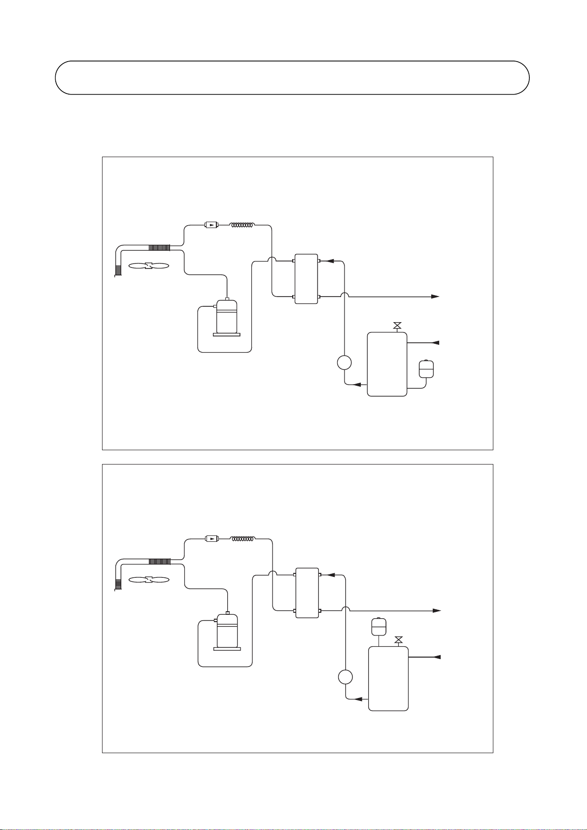
A4AC / AMAC 20C / 25C / 30C
Water / Refrigerant Circuit Diagram
FIL TER
DRIER
CAP TUBE
BPHE
AUT O PRESS RELIEF V ALVE
WATER
OUT
COMPRESSOR
WATER PUMP
P
WATER ST ORAGE
TANK
A4AC / AMAC 40C / 50C / 60C
Water / Refrigerant Circuit Diagram
FIL TER
DRIER
CAP TUBE
BPHE
EXP ANSION
COMPRESSOR
WATER
IN
EXP ANSION
TANK
PART NO : 70-03-4-067460
WATER
OUT
TANK
AUT O PRESS RELIEF V ALVE
WATER
IN
WATER PUMP
7
P
WATER ST ORAGE
TANK
PART NO : 70-03-4-087461
Page 10
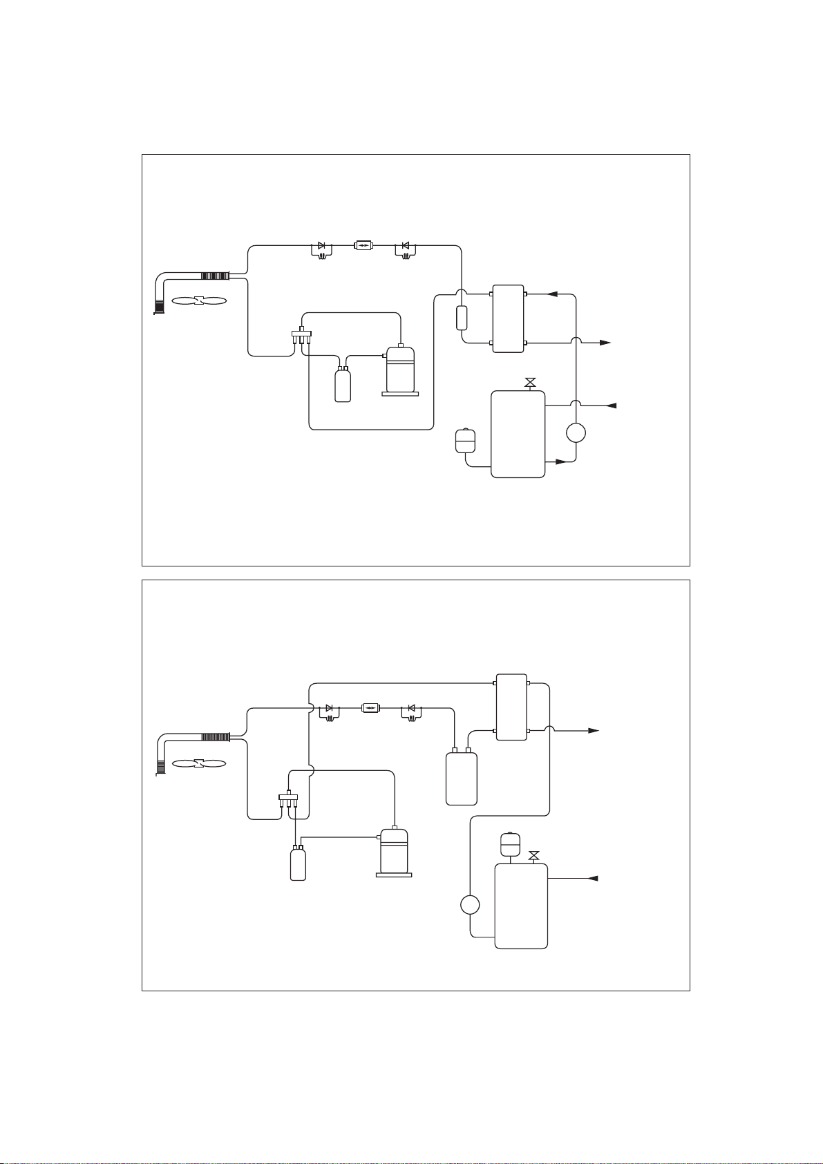
A4AC / AMAC 20CR / 25CR / 30CR
Water / Refrigerant Circuit Diagram
CHECK
VALV E
HEATING
CAP
TUBE
SUCTION
ACCUMULATOR
FILTER
DRIER
CHECK
VALV E
COOLING
CAP
TUBE
COMPRESSOR
EXPANSION
TANK
BPHE
CHARGE
COMPENSATOR
AUTO PRESS RELIEF VALVE
WATER STORAGE
TANK
PART NO : 70-03-4-067458
AMAC 40CR / 50CR, A4AC/ AMAC 60CR
Water / Refrigerant Circuit Diagram
WATER
OUT
WATER
IN
P
HEATING
SUCTION
ACCUMULATOR
CHECK
VALV E
CAP
TUBE
FILTER
DRIER
COOLING
COMPRESSOR
CHECK
VALV E
CAP
TUBE
WATER PUMP
LIQUID
RECEIVER
P
WATER STORAGE
BPHE
TANK
EXPANSION
TANK
AUTO PRESS RELIEF VALVE
PART NO : 70-03-4-067459
WATER
OUT
WATER
IN
8
Page 11

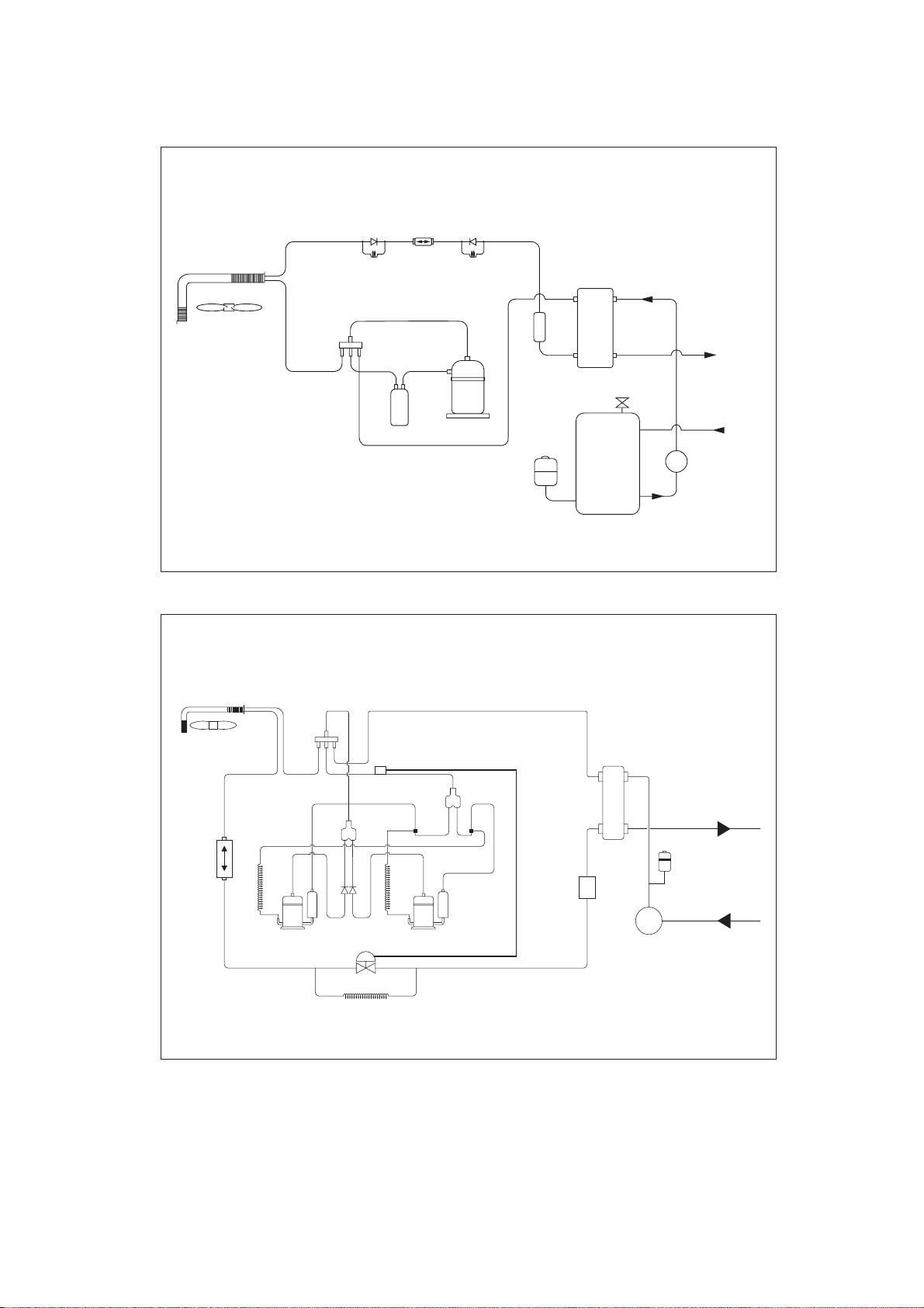
A4AC / AMAC 80C / 100C / 120C / 150C
Water / Refrigerant Circuit Diagram
FIN TUBE
HEA T EXCHANGER
(SYSTEM 1)
FIL TER DRIER FIL TER DRIER
COMPRESSOR COMPRESSOR
A4AC / AMAC 80CR / 100CR / 120CR / 150CR
THERMOST ATIC
EXP ANSION
VA L V E
BRAZED PLA TE
HEA T EXCHANGER
WATER
OUTLET
WATER
INLET
THERMOST ATIC
EXP ANSION
VA L V E
FIN TUBE
HEA T EXCHANGER
(SYSTEM 1)
Water / Refrigerant Circuit Diagram
FIN TUBE
HEA T EXCHANGER
(SYSTEM 1)
HEA TING
FIL TER
DRIER
COOLING
WATER
OUT
CAP
TUBE
CAP
TUBE
HEA TING
TUBE
COOLING
TUBE
CHECK
4-WAY VAL VE
COMPRESSOR COMPRESSOR
SUCTION
ACCUMULA TOR
VA L V E
CHECK
VA L V E
LIQUID
RECEIVER
CAP
CAP
WATER
FIL TER
DRIER
IN
LIQUID
RECEIVER
CHECK
VA L V E
CHECK
VA L V E
HEA T EXCHANGER
SUCTION
ACCUMULA TO R
FIN TUBE
(SYSTEM 2)
4-WAY VA LVE
PAR T NO : 70-03-4-056764
9
Page 12
A5AC 20CR / 25CR
Water / Refrigerant Circuit Diagram
CHECK
VALV E
FILTER
DRIER
CHECK
VALV E
WATER / REFRIGERANT
HEATING
CAP
TUBE
SUCTION
ACCUMULATOR
COOLING
CAP
TUBE
COMPRESSOR
EXPANSION
CHARGE
COMPENSATOR
TANK
BPHE
AUTO AIR VENT
WATER STORAGE
TANK
A5AC 30CR
Water / Refrigerant Circuit Diagram
WATER
OUT
WATER
IN
WATER PUMP
P
PART NO : 70-03-4-080547
FILTER
DRIER
OIL
RETURN
TUBE
4WV
COMPRESSOR 1
CHECK
VALV E
TXV
OIL
RETURN
TUBE
COMPRESSOR 2
TWIN TUBE
JOINT
CHARGE
COMPENSATOR
BPHE
WATER OUT
EXPANSION TANK
WATER IN
PUMP
10
Page 13

W
A5AC 40 / 50CR
Water / Refrigerant Circuit Diagram
4WV
SUB ACCUMULATOR
TWIN TUBE
JOINT
BPHE
WATER
OUT
FILTER
DRIER
RETURN
TUBE
WATER / REFRI
OIL
COMPRESSOR 1
4WV
CHECK
VALV E
TXV
OIL
RETURN
TUBE
COMPRESSOR 2
A5AC 55CR
LIQUID RECEIVER
Water / Refrigerant Circuit Diagram
BPHE
SUB ACCUMULA TO R
TWIN TUBE
JOINT
PUMP
EXPANSION
TTANK
WATER
WATER
OUT
IN
FIL TER
DRIER
OIL
RETURN
TUBE
COMPRESSOR 1
CHECK
VA LV E
TXV
OIL
RETURN
TUBE
COMPRESSOR 2
11
LIQUID RECEIVER
PUMP
EXP ANSION
TANK
WATER
IN
Page 14

CHILLER PANEL CONTROLLER
1. SAFETY CONSIDERATION
Only specially trained and technicians and installers are authorized to install and service this
equipment..
1.1 General Installation Recommendations
• Only supply DC voltage (9-17V, typically 12V, maximum current 200mA) as a power source
to the device.
• Input contact voltage supply should limit to 12VDC or 24VAC.
• Isolated all the low voltage wiring (communication bus, etc) from high voltage power supply
wiring.
2. GENERAL DESCRIPTION
2.1 General
The chiller panel controller is designed to control the chiller operation. This device allows the
user to have customized control for each connected unit.
2.2 Features
The requirements of user friendly and easy to use have been taken into account in designing
this chiller panel controller. It can do the task as follow:
• Whole system configuration
• Unique parameter settings
• Operation status display
• Tracing fault record (easy in hardware troubleshooting)
The display is shown in an 8-lines graphical LCD display. There are 8 dedicated keys available
in the panel,
• Menu selection
• Navigation on the screen
• Modification of the selected value
During first start-up, the panel will have a default configuration (timer schedule, set point,
miscellaneous settings, etc) User can do the changes on that particular configuration later.
2.3 Panel Position
The chiller panel controller can be installed anywhere, as long as it is easy to accessed by
authorized personnel.
The requirements of installation are:
• Avoid exposure to shocks
• Avoid any source of electromagnetic pollution
• Avoid installation on uneven vertical surface
2.4 Operation Environmental Condition
• Temperature:
-10°C to 65°C operating temperature
-20°C to 85°C storage temperature
• Relative Humidity:
0 to 95% non-condensing
12
Page 15
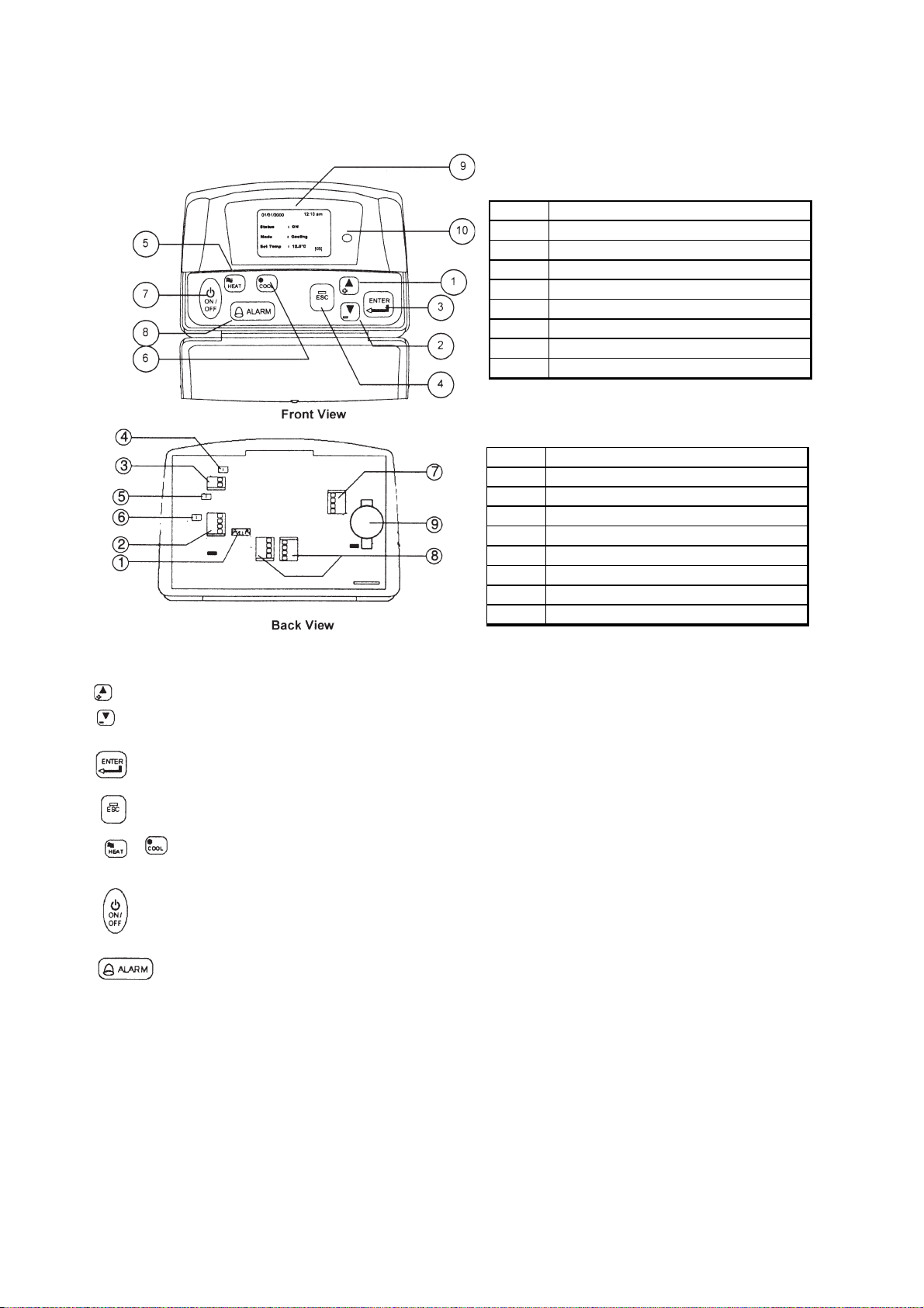
3. HARDWARE DESCRIPTION
Legend
3.1 Key Explanation
1 & 2
Navigation key
3 Execute instruction key
4 Cancel instruction key
5 Switching to heat mode shortcut key
6 Switching to cool mode shortcut key
7 Toggle ON/OFF shortcut key
8 Show alarm k ey
9 Graphical LCD display
10 ON/OFF indicator
Legend
1 & 2
Chiller terminal unit connection
3 Not avai lab le
4 CMOS rset jumper (JH2)
5 Chiller bus resist or configuration (JH3)
6 Not avai lab le
7 Not avai lab le
8 Not avai lab le
9 Not avai lab le
10 Bac kup battery
The 2 navigation keys permit item selection and modifying the selected value.
ENTER key is used to execute the navigation instruction
ESC key is used to cancel the navigation instruction
Shortcut key to switch the operation mode in the summary pages
Shortcut key to trigger ON/OFF in the summary pages
Shortcut key to show fault / alarm in the summary pages
13
Page 16

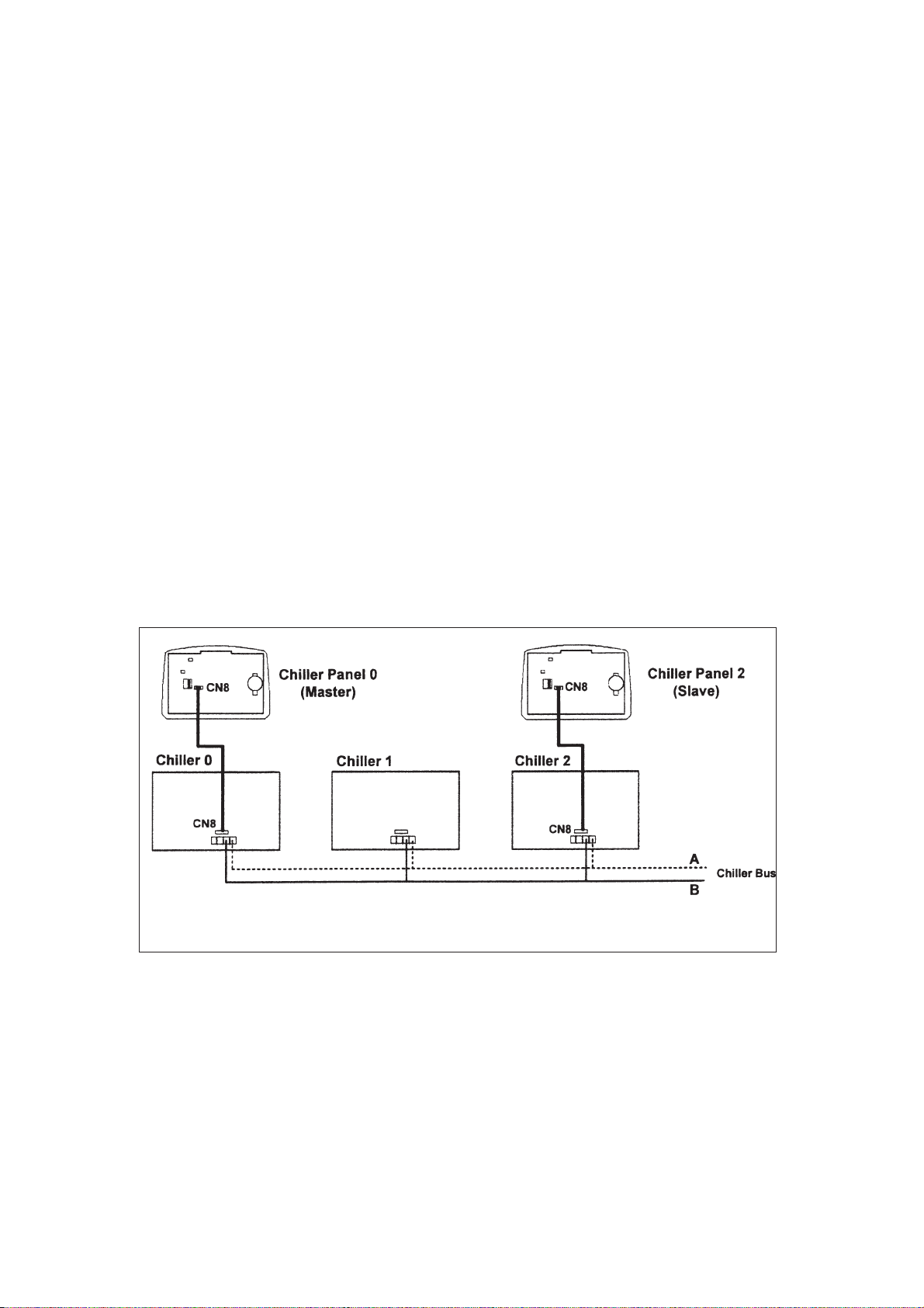
4. INSTALLATION
4.1 Chiller Bus
Supported up to 50 units of Chiller
Chiller 0 Chiller 1 Chiller 2
5 way wire (CM8)
Chiller
Communication bus
Chiller Panel 0 Chiller Panel 1
(Master) (Slave)
Chiller Network
Chiller panel needs to be energized with +12Vdc. The 5 way wires that provided is once on the easiest
solution to establish a communication between the panel and chiller main board (CN8-CN8). If the 5-way
wires socket has been occupied in main board, just using 2 insulation wired are needed to establish a
communication between panel and chiller main board.
Chiller panel can support maximum up to 50 units of chiller. In the chiller network, duplication of main board
unit address is not allowed. Each chiller main board should have their unique unit address (0-50).
For first time running, user need to assign a unique unit address to each main board in the chiller network.
User should follow the procedure below:
• Only power ON one main board at once time. Make sure not others main boards are energize.
• By using the panel connected to the main board.
<ENT ER> <ENT ER>
Summary Pages Main Menu Setting Menu
<ENTER>
G7 Unit No 1. General Set Paraameter
<ENT ER> <ENT ER>
key in "0001" as p assw ord
• Key in unique unit address and press ENTER to execute.
• De-energized the main board and repeat the procedures again all the main boards have been
assigned a unique unit address.
IMPORTANT : Do not assign a same unit address to more than one chiller main board.
RECOMMENDATION : Please select a coherant model (G1 Model) to all the chiller main boards in
the same network.
14
Page 17
4.2 Others Configuration
• JH2 in chiller panel should let it open (put the jumper header on one pin only) all the time
unless user need to do CMOS reset to that particular panel.
• JH3 should let it open (put the jumper header on one pin only) all the time as well.
• Remember to put in the coin cell battery on the panel. Without the backup battery, the panel will
always reset the time to 12:00am, 1st Jan 2000.
4.3 Installation of the Chiller Panel Controller
• Disconnect the unit and ensure no others unit energy source that supplies the panel.
• Open the rear panel of the Chiller Panel (insert a ‘flat-head’ screwdriver in the top joint of main
casing with rear panel to open the real panel).
• Pass the necessary wires of the panel across the large opening in the rear panel. Place the rear
panel flat support against the wall and make marks on the wall through the four installation holes
(inner and outer).
• Drill four appropriate holes in the marked places.
• Attach the rear panel to the wall and put on the screws on it. Ensure that all cables are passed
through the hole of the rear panel.
• Connect the wires to the corresponding terminal according to the wiring bus network. The
power supply and communication wires must be correctly connected to ensure that the
panel works.
• Close the chiller panel (ensure the bottom joint is aligned for the casing, then complete others joint
part. Ensure that the contacts at the back of the panel are aligned with each others).
Bus Wiring Diagram
15
Page 18

5. SOFTWARE DESCRIPTION
5.1 Introduction
The Chiller Panel Controller can be used to control / display the status of Chiller.
Status viewing:
• ON/OFF status
• Mode (Cooling / Heating/ Boiling)
• Mode set temperature
• Compressor status (ON/OFF/ DEFROST)
• Water in, Water Out, Outdoor air and Panel temperature
• Chiller model (Chiller, Heat Pump, Chiller/ Boiler, Chiller+Boiler, Heat Pump/Boiler, Heat Pump+
Boiler
• Advance parameter settings
• Defrost sensor temperatures
• Compressor discharge sensor temperatures
• Compressor run times
• Incoming alarm/ fault/ error
Status settings:
• ON/OFF switching
• Mode setting (Cooling / Heating/ Boiling)
• Mode set temperature
• Manual entering defrost
• Advance parameter settings
• Password changing
• Panel option setting (Backlight, Alarm Buzzer, Screen saver, Contrast, Brightness, temperature
unit)
• Time and date settings
• Clearing compressor run time
16
Page 19
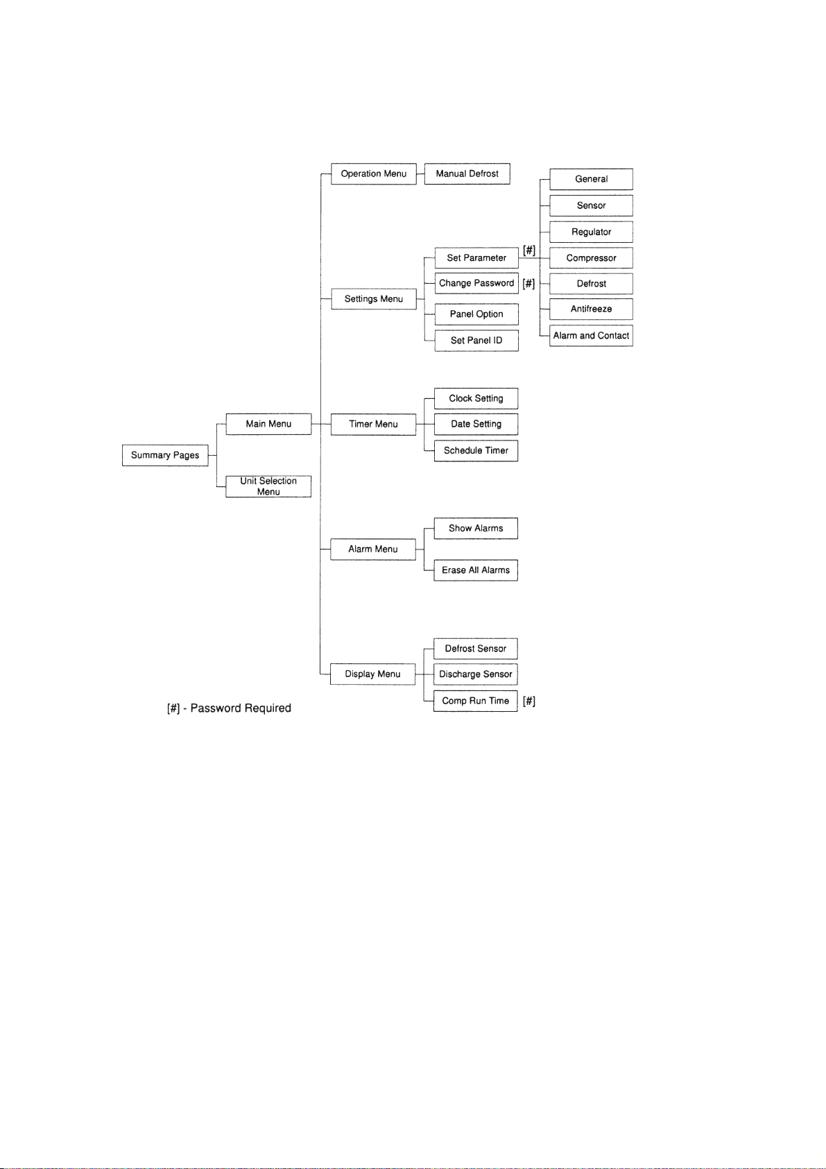
5.2 Menu Structures
Menu Structure Diagram for Chiller
17
Page 20

5.3 Chiller Menu Structure
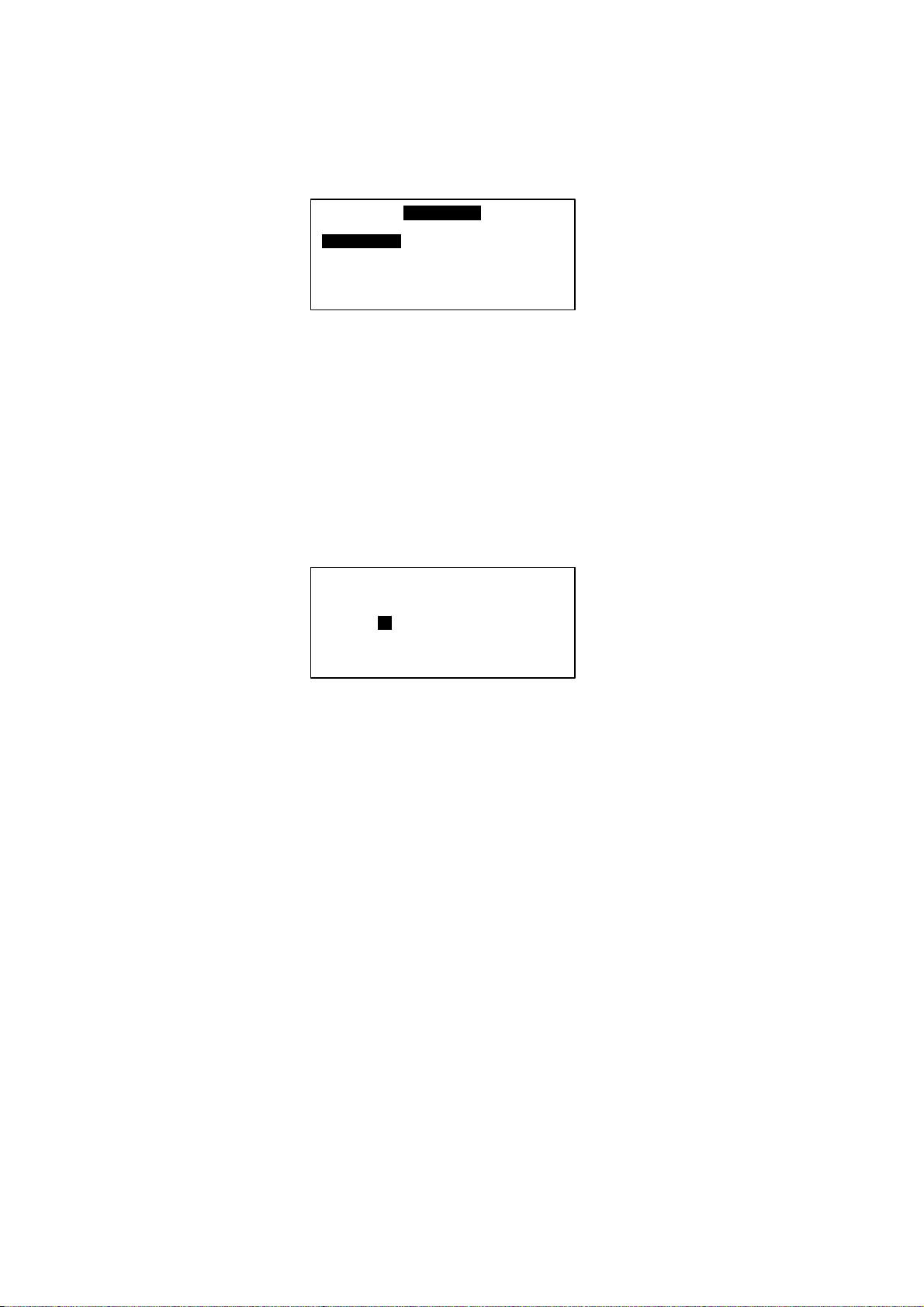
5.31 Summary Pages
There are 4 pages in [Summary Pages]. Press UP or DOWN for page scrolling. Press ENTER to go to
[Main Menu]. Time and date are shown on top of each page. Beside that, the bottom of each page shows
current control unit of the Chiller.
For example: [00] - Chiller Panel controls Chiller ID 0 currently
[03] - Chiller Panel controls Chiller ID 3 currently
[All] - Chiller Panel controls all Chiller currently
1st page: Display ON/OFF status, Mode settings and Temperature settings.
01/01/2000 12:00am
Status : ON
Mode : Cooling
Cool Temp : 12.0°C
[00]
2nd page: Display Compressor status.
01/01/2000 12:00am
Compressor : ON
[00]
3rd page: Display Water In, Water Out, Outdoor air and Panel temperature
01/01/2000 12:00am
Water In :19.8°C
Water Out : 25.6°C
Outdoor Air : 32.2°C
Panel : 20.5°C
[00]
4th page: DisplayChiller model, Compressor No. and Chiller ID.
01/01/2000 12:00am
Model : Chiller
No. Comp : 1 Comp
Unit No : 0
18
Page 21

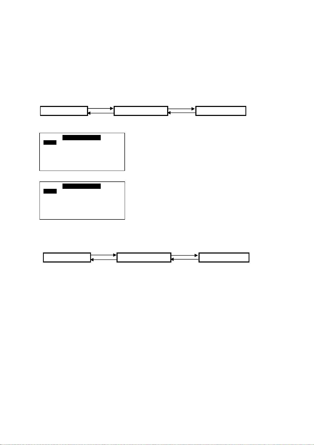
5.3.2 Main Menu
Press ENTER in [Summary Pages] to go into this menu
MA I N MENU
Operating Menu
Setting Menu
Ti me r Me nu
A larm Men u
Dis play Menu
There are 5 sub menus in [Main Menu]. Press UP or DOWN to select sub menus, ENTER to enter into
the sub menu or press ESC to exit to [Summary Pages]
5.3.2.1 Operation Menu
Select [Operation Menu] in [Main Menu] and press ENTER to go into this menu.
OPERAT ION MENU
Status : ON
Mode : Cooling
Cool Te mperature : 12.0° C
Heat Te mperature : 40.0° C
Some normal settings can be found here. Press UP or DOWN to select each settings, ENTER to start the
setting or press ESC here to exit to [Main Menu]
Settings : -ON/OFF unit
- Mode changing (Cooling/ Heating/ Boiling)
- Cooling temperature setting
- Manual Defrost Selection
5.3.2.1.1 Manual Defrost
Select [Manual Defrost] in [Operation Menu] and press ENTER to go into this menu.
This menu lets user select one compressor to enter into defrost cycle manually, as long as the
environment fulfill the defrost requirement.
Def r ost Compres s or
Co mp 1
19
Page 22

5.3.2.2 Settings Menu
Select [Settings Menu] in [Main Menu] and press ENTER to go into this menu.
SETTINGS MENU
Set Parameter
Change Passw ord
Panel Option
Set Panel ID
Some advance settings can be found here. Press UP or DOWN to select settings, ENTER to start the
setting or press ESC here to exit to [Main Menu].
Settings - Set Parameter
- Password Changing
- Panel Option
- Set Panel ID
5.3.2.2.1 Set Parameter
Select [Set Parameter] in [Settings Menu] and press ENTER to go into this menu.
1.General
2. Sensor
3. Regulator
4. Compressor
5. Def rost
6. Antif reeze
7. Alarm and Contact
There are 7 groups of advance parameters for user to set in this menu, Press UP or DOWN to
select the group, ENTER to go into the group or ESC to exit to [Setting Menu].
Settings:- General
- Sensor
- Regulator
- Compressor
- Defrost
- Antifreeze
- Alarm and Contact
5.3.2.2.2 Password Changing
Select [Password Changing] in [Setting Menu] and Press ENTER to go into this menu.
Please enter the
Old password ………..
0
- - - -
User can change the old password in this menu.
Press ESC to exit to [Settings Menu].
20
Page 23

5.3.2.2.3 Panel Option
Select [Panel Option] in [Setting Menu] and Press ENTER to go into this menu.
Back light :
Buzzer : On
Scree n Saver : Disable
Timeout : 5m
Contrast : 50%
Br ig ht ness : Me dium
Temp Unit : ° C
: Nor m a l
User can do some miscellaneous for the panel. These settings would not affect whole system performance.
Settings - Toggle Backlight
- Alarm Buzzer
- Enable / Disable Screen Saver
- Screen Saver timeout
- Contrast display
- Backlight brightness
- Temperature unit
Press ESC to exit to [Settings Menu]
5.3.2.2.4 Set Panel ID
Select [Set Panel ID] in [Settings Menu] and press ENTER to go into this menu.
Ple ase enter the
Panel ID……
=> Unit 0
User can assign the ID no, to the panel.
Example: If ID no. 0 has been assigned, the panel acts like Master Panel Unit. It can choose to control
each Chiller in the network.
If other ID no. (1-50) has been assigned, the panel acts like Slave Panel Unit. It is dedicated to
one particular Chiller. It can only control the Chiller with same ID in the network.
Press [ESC] to exit to [Settings Menu]
21
Page 24
5.3.2.3 Time Menu
Select [Time Menu] in [Main Menu] and press ENTER to go into this menu.
Cl o ck Se tting :
Dat e Setting
Time Schedule
Timer : Dis able
TIMER MENU
All the timer/ schedule settings are included in this menu. Press UP or DOWN to select each settings.
ENTER to start the setting or press ESC here to exit to [Main Menu].
Settings: - Set Clock
- Set Date
- Set Schedule ( 7 days Programmable Timer)
- Enable/ Disable Timer Schedule
5.3.2.3.1 Set Clock
Select [Clock Setting] in [Timer Menu] and press ENTER to go into this menu.
Se t Time :
hh: mm
00: 00
User can set the time in this menu. The time setting is in 24-hour format.
Pres [ESC] to exit to [Timer Menu].
22
Page 25

5.3.2.3.2 Set Date
Select [Date Setting] in [Timer Menu] and press ENTER to go into this menu.
Set Time :
yyyy hh mm
2000 /01 / 01
User can set the date in this menu. The date is set according to sequence below:
(year) / (month) / (day)
Press [ESC] to exit to [Timer Menu].
5.3.2.3.3 Set Schedule
Select [Schedule Timer] in [Timer Menu] and press ENTER to go into this menu.
Timer 1 Timer2
Sun 0800 1600 _ _ _ _ _ _ _ _
Mon 0800 1600 _ _ _ _ _ _ _ _
Tue 0800 1600 _ _ _ _ _ _ _ _
Wed 0800 1600 _ _ _ _ _ _ _ _
ON OFF ON OFF
This is the 7 days programmable timer schedule menu. There are 2 ON/OFF events in one day. User can
choose to set each day of week (Sunday - Saturday) ON/OFF timer. Before this schedule carry their
effect to the Chiller, user need to set the [Timer] in [Timer Menu] to enable.
Press [ESC] to exit to [Timer Menu].
5.3.2.4 Alarm Menu
Select [Alarm Menu] in [Main Menu] and press ENTER to go into this menu.
ALARAM MENU
Show Alarms
Erase All Alarm
This place keeps records for all previous occurred fault/ alarms. User can view the alarm history and
clear
that record (alarm history) as well. The panel can keep up to 20 fault/ alarm records.
Press ESC to exit to [Main Menu]
23
Page 26

5.3.2.4.1 Show Alarms
Select [Show Alarms] in [Alarm Menu] and press ENTER to go into this menu.
[Ch 0]
Alarm 1
Comp 1 over load
01/ 01/ 00 12:00am
User can view all the fault/ alarm records in this menu.
The record shows - Alarm type
- Alarm occurred date
- Alarm occurred time
- Alarm occurred unit (Chiller ID)
Beside that, user can erase the alarm record in this menu.
Press [ESC] to exit to [Alarm Menu].
5.3.2.4.2 Erase All Alarms
Select [Erase All Alarms] in [Alarm Menu] and press ENTER to go into this menu.
Are you sure ?
Press Enter to er ase,
or ESC to exit.
User can rase all the alarm / fault records at once in this menu.
Press [ESC] to exit to [Alarm Menu].
5.3.2.5 Dispaly Menu
Select [Display Menu] in [Main Menu] and press ENTER to go into this menu.
DISPL AY M ENU
De fr ost Se nsor
Dis char ge Sens or
Comp Run Time
This menu display Defrost Sensor temperature, Compressor Discharge sensor temperature and
Compressor Run Time. Beside that, user can clear each Compressor Run Time for Chiller.
Press [ESC] to exit to [Main Menu]
24
Page 27

5.3.2.5.1 Defrost Sensor
Select [Defrost Sensor] in [Display Menu] and press ENTER to go into this menu.
De fr os t Se nsor
Comp 1 : 12.8° C
User can view the defrost sensor temperature for each compressor in the Chiller.
Press [ESC] to exit to [Display Menu]
5.3.2.5.2 Discharge Sensor
Select [Discharge Sensor] in [Display Menu] and press ENTER to go into this menu.
Dis ch arges Sens or
Comp 1 : 36.5° C
User can view the discharge sensor temperature for each compressor in the Chiller.
Press [ESC] to exit to [Display Menu].
5.3.2.5.3 Comp Run Time
Select [Comp Run Time] in [Display Menu] and press ENTER to go into this menu.
Comp Run Time
Comp 1 : 13579h
User can view the compressor run time for each compressor in the Chiller. Beside that, user can
clear each compressor run time in this menu. User needs to key in the correct password before
clearing the compressor run time.
Press [ESC] to exit to [Display Menu].
25
Page 28

6. OPERATION USER MANUAL
6.1 Starting
Chiller panel can be set as Master or Slave panel unit. When the Panel ID is set to ‘0’, it acts like a Master
panel, whereas it is Slave panel if Panel ID is set to others number (1-50).
Chiller panel can control the Chiller if both ID no. (Panel ID and Chiller ID) are same.
For example: Panel ID 1 can only control Chiller ID 1
Master Panel can choose to control each Chiller or control all Chiller at once in the network.
For example : Panel ID 0 (master) can control Chiller ID 0 / ID 1/ ID 32 .... or all Chillers at once.
Panel ID can be set in Set Panel ID in Settings Menu.
Ple ase enter the
Panel ID ……
=> Unit 0
26
Page 29

6.2 Chiller Operation Control
[00]
[00]
[00]
6.2.1 Starting
During power on for the Chiller Panel, it needs to take several times to collect information from the Chiller.
At this time, all the status will show “--”. Please ensure the particular Chiller exists in the network. When
the process is completed, user can start to control the Chiller using the panel.
01/ 01/ 2000 12:00am
Status : --
Mode : --
Cool Temp : --
01/ 01/ 2000 12:00am
Status : ON
Mode : Cooling
Cool Temp : 12° C
In gathering information process Gathering information completed
6.2.2 Changing Display Unit
Chiller Panel (Master) can choose to choose to control / display each Chiller status. This can be done in
[Summary Pages] only.
01/ 01/ 2000 12:00am
Status : ON
Mode : Cooling
Cool Temp : 12° C
Unit Selection :
Select All
Select One : 0
In [Summary Pages], press and hold ENTER buttom
(1 second) to go into [Unit Selection] menu.
Select “Select All” and press ENTER if user want to
control all Chilelr in the network, or select “Select One”
to control a particular Chiller. Press ESC to exit to
[Summary Pages].
Unit Selection :
Select All
Select One : 0
Select a Chiller ID via UP or DOWN and press ENTER
to confirm or ESC to cancel.
27
Page 30
6.2.3 Switching ON/OFF
There are several ways to switch ON/OFF for the Chiller.
i) [Summary Pages]
Press and hold ON/OFF button (hold 1 second). Please note that the ON/OFF button will only function
in
[Summary Pages].
ii) [Operation Menu]
<ENTER> <ENTER>
Summary Pages Main Menu Operation Menu
<ESC> <ESC>
OPERATION M ENU
Stat us : O N
Mode : Cooling
Cool Temperature : 12.0° C
Heat Temperature : 40.0° C
OPERATION M ENU
Stat us : O N
Mode : Cooling
Cool Temperature : 12.0° C
Heat Temperature : 40.0° C
In [Operation Menu], select “Status” and press
ENTER.
Toggle ON/OFF via UP or DOWN button, and then
press ENTER to confirm the change or ESC to cancel.
iii) [Timer Menu]
<ENTER> <ENTER>
Summary Pages Main Menu Timer Menu
<ESC> <ESC>
7 days programmable time can turn chiller ON/OFF. User can set the schedule in this
[Timer Menu]. Please refer 6.2.11 (page 27) for schedule settings.
28
Page 31

6.2.4 Switching Mode
There are several ways to switch the mode for the Chiller. Please take note that some mode cannot be set
due to current Chiller model settings.
Mode
Chiller Model
Chiller √ ×× √ - Allow to set
Heat Pump √√× × - Not Allow to set
Chiller / Boiler √ × √ Auto - Turn ON automatically
Heat Pump /Boiler √√√
Chiller + Boiler √ ×Auto
Heat Pump + Boiler √√Auto
Cooling Heating Boiling
i) [Summary Pages]
Cooling - Press and hold COOL button.
Heating - Press and hold HEAT button (if it allows to set).
Boiling - Press and hold HEAT button again (if it allows to set).
ii) [Operation Menu]
<ENTER> <ENTER>
Summary Pages Main Menu Operation Menu
<ESC> <ESC>
OPERATION MENU
Status : O N
Mode : Cooling
Cool Temperature : 12.0° C
Heat Temperature : 40.0° C
OPERATION M ENU
Stat us : O N
Mode : Cooling
Cool Temperature : 12.0° C
Heat Temperature : 40.0° C
In [Operation Menu], select “Mode” and press
ENTER to start setting or ESC to exit to [Main
Menu]
Toggle ON/OFF via UP or DOWN button, and then
press ENTER to confirm the change or ESC to
cancel.
29
Page 32

6.2.5 Changing Mode Set Temperature
There are 2 ways to change the mode set temperature for the Chiller.
i) [Operation Menu]
OPERATION MENU
Status : ON
Mode : Cooling
Cool Temperature : 12.0°C
Heat Temperature : 40.0°C
In [Operation Menu], select “Cool Temp” / “Heat
Temp”and press ENTER start setting or ESC to exit
to [Main Menu].
OPERATION MENU
Status : ON
Mode : Cooling
Cool Temperature : 12.0°C
Heat Temperature : 40.0°C
Change value via UP or DOWN button, and then
press
ENTER to confirm the change or ESC to cancel.
ii) [Set Parameter]
<ENTER> <ENTER>
Summary Pages Main Menu Settings Menu
<ESC> <ESC>
<ENTER> <ESC>
Key in Password
Set Parameter
1. General
2. Sensor
3. Regulator
4. Compressor
5. Defrost
6. Antifreeze
7. Alarm and Contact
R1 Cool SP : 12.0° C
R2 Cool Diff : 3.0° C
R3 Heat SP : 40.0° C
R4 Heat Diff : 3.0° C
R5 Min Cool SP : -20° C
R6 Max Cool SP : 40° C
R7 Min Heat SP : -20° C
In [Set Parameter], select “Regulator” and press
ENTER. Press ESC tp exit to [Main Menu].
Select “R3”/ “R5” and press ENTER to start setting or ESC to exit to [Set Parameter] menu.
R1 Cool SP : 12.0° C
R2 Cool Diff : 3.0° C
R3 Heat SP : 40.0° C
R4 Heat Diff : 3.0° C
R5 Min Cool SP : -20° C
R6 Max Cool SP : 40° C
R7 Min Heat SP : -20° C
Change value via UP or DOWN button. The
boarderline is limited by R5&R6 (cool),
R7&R8(heat).
Press ENTER to confirm or ESC to cancel.
30
Page 33

6.2.6 Manual Defrost
User can choose which compressor will go into manual defrost cycle by using the Chiller Panel, as long
as the condition is fulfilled with defrost condition. This can be done in [Operation Menu].
<ENTER> <ENTER>
Summary Pages Main Menu Operation Menu
<ESC> <ESC>
Please take note that “Manual Defrost” option will only available in HEATING mode. It will disappear in
COOLING/ BOILING mode.
OPERATION M ENU
Stat us : O N
Mode : Cooling
Cool Temperature : 12.0° C
Heat Temperature : 40.0° C
OPERATION MENU
Status : O N
Mode : He at in g
Coo l Tem per ature : 12.0° C
Heat Temperature : 40.0° C
“Manual Defrost” disappear when Chiller not in HEATING mode
OPERATION M ENU
Status : O N
Mode : He ating
Cool Temperature : 12.0° C
Heat Temperature : 40.0° C
Manual Defrost
Defrost Compressor
Comp 1
In [Operation Menu], select [Manual Defrost], press
ENTER to go into it, or ESC to exit to [Main Menu].
Select which compressor to go into defrost cycle via
UP or DOWN button. Press ENTER to confirm or ESC
to exit to [Operation Menu].
31
Page 34

6.2.7 Advance Parameter Settings
The Chiller Panel provide user a lot of advance parameter settings for the Chiller. The parameters are
divided into 7 groups. There all are stored in [Set Parameter] menu and it is password-procteted layer
in the panel.
* CAUTION : INPROPER SETTINGS WILL CAUSE PERMANENT DAMAGE TO THE CHILLER !!!
<ENTER> <ENTER>
Summary Pages Main Menu Settings Menu
<ESC> <ESC>
<ENTER> <ESC>
Key in Password
Set Parameter
7 groups of Advance Parameter:
1) General
G1 Model : Chiller
G2 No. Comp : 1 Comp
G3 On/Off in : Disable
G4 Col/ Heat In : Disable
G5 Ext Alarm in : Disable
G6 Water Sys : Isolated
G7 Unit No : 0
2) Sensor
S1 Water Enter : 0.0° C
S2 Water Leave : 0.0° C
S3 Air Sensor : 0.0° C
S4 Defrost 1 : 0.0° C
S5 Defrost 2 : 0.0° C
S6 Defrost 3 : 0.0° C
S7 Defrost 4 : 0.0° C
3) Regulator
R1 Cool SP : 12.0° C
R2 Cool Diff : 3.0° C
R3 Heat SP : 40.0° C
R4 Heat Diff : 3.0° C
R5 Mix Cool SP : -20° C
R6 Max Cool SP : 40° C
R7 Min Heat SP : -20° C
S8 Cp Dish 1 : 0.0° C
S9 Cp Dish 2 : 0.0° C
S10 Cp Dish 3 : 0.0° C
S11 Cp Dish 4 : 0.0° C
R8 Max Heat SP : 90° C
R9 Ax Heat SP : 5.0° C
R10 Ax Heat Diff : 2.0° C
R11 Au Bo SP : 5.0° C
R12 Au Bo Diff : 2.0° C
R13 Au Bo Start : 30m
32
Page 35

4) Compressor
A
C1 Min Run : 12s
C2 Min Stop : 240s
C3 2On Interval : 360s
C4 2Cp ON Dly : 15s
C5 P-Cp ON Dly : 60s
C6 Cp-P OFF Dly : 60s
C7 Cp Cut Off : 120° C
5) Condenser Defrost
D1 Start Temp : -3° C
D2 End Temp : 14° C
D3 Max Dura : 10m
D4 Interval : 45m
D5 Dly Bfr Def : 0s
D6 Dly Aft Def : 0s
6) Cool Mode Antifreeze
1 Heater SP : 5° C
A2 Heater Diff : 2.0° C
A3 Sensor : Leave
A4 Alarm SP : 3° C
A5 Alarm Diff : 2.0° C
7) Alarm and Contact
P1 FS Confirm : 5s
P2 FS Delay : 180s
P3 LP Delay : 30s
P4 CO Reset : Manual
P5 HP Rest : Auto
P6 LP Reset : Auto
P7 FO Reset : Manual
P8 RO Reset : Manual
P9 FS Reset : Manual
P10 Aux Reset : Manual
P11 A/F Reset : Manual
P12 CO Contact : Normal
P13 HP Contact : Normal
P14 LP Contact : Normal
Please refer to 8. APPENDIX for detail desciption.
P15 FO Contact : Normal
P16 PO Contact : Normal
P17 FS Contact : Normal
P18 EA Contact : Normal
P19 DE Contact : Normal
33
Page 36

6.2.8 Changing Password
For security purpose, some places in the panel are password-proctected. User can change the password
at anytime.
<ENTER> <ENTER>
Summary Pages Main Menu Settings Menu
<ESC> <ESC>
<ENTER> <ESC>
Change Password
Please enter the
Old password -----------
0
----
Password accepted . . .
Access granted !
User needs to enter the old password in order to change
the password.
Change the 1st digit value via UP or DOWN. Press
ENTER to start enter 2nd digit and the rest, or ESC to
exit at anytime.
If password correct, this message will be
shown and proceed to new password
settings.
Please enter the
New password -----------
0
----
Password error . . .
Access denied !
If password not correct, this message will be
shown and exit to [settings Menu]
Same as previous, UP DOWN to change value, ENTER
to go to next digit, ESC to exit.
User is not allowed to set the password to 0000.
New password
Has been set …….
If new password is accepted, this message
will be shown and then exit to [Settings Menu].
New password
‘0 0 0 0’
Is not accepted ………
If new password is ‘0000’, this message
will be shown and then exit to [Settings Menu].
The password remains as previous.
34
Page 37

6.2.9 Clock Setting
User can set the clock for the panel.
<ENTER> <ENTER>
Summary Pages Main Menu Timer Menu
<ESC> <ESC>
<ENTER> <ESC>
Se t Time :
hh mm
00 : 00
UP or DOWN to change ‘hour’. ENTER to set ‘minute’
or ESC to exit to [Timer Menu].
UP or DOWN to change ‘minute’. ENTER to confirm
or ESC to set ‘hour’again.
6.4.10 Date Setting
User can set the date for the panel.
<ENTER> <ENTER>
Summary Pages Main Menu Timer Menu
<ESC> <ESC>
<ENTER> <ESC>
Set Time
Se t Time :
yyyy hh mm
2000 /01 / 01
Set Time
UP or DOWN to change ‘year’. ENTER to set ‘month’ or
ESC to exit to [Timer Menu].
UP or DOWN to change ‘month’. ENTER to set ‘day’ or
ESC to set ‘year’ again.
UP or DOWN to change ‘day’. ENTER to confirm or
ESC to set ‘month’ again.
35
Page 38

6.2.11 7 days Programmable Setting
_ _ _ _
_ _ _ _
The are 2 ON/OFF events in one day for the schedule. This schedule is applicable to all the chillers in
the network.
Timer 1 Timer 2
ON OFF ON OFF
Sun 0800 1600 _ _ _ _ _ _ _ _
Mon 0800 1600 _ _ _ _ _ _ _ _
Tue 0800 1600 _ _ _ _ _ _ _ _
Wed 0800 1600
_ _ _ _
UP or DOWN select day of week, ENTER
to select event or ESC to exit to [Timer Menu].
Timer 1 Timer 2
ON OFF ON OFF
Sun 0800 1600 _ _ _ _ _ _ _ _
Mon 0800 1600 _ _ _ _ _ _ _ _
Tue 0800 1600 _ _ _ _ _ _ _ _
Wed 0800 1600
_ _ _ _
UP or DOWN select event. ENTER to start
setting or ESC to back to select day of week.
Event setting is same like time setting. User can
disable the event by set it to ‘- - - -’
Before the schedule will carry the effect, user need to set ENABLE for “TIMER” in [Timer Menu].
TIMER MENU
Set Time
Set Date
Set Schedule
Timer : Disable
Select “Timer” and press ENTER to start the
settings. UP or DOWN to toggle Enable/ Disable,
ENTER to confirm or ESC to cancel.
36
Page 39

6.2.12 Viewing Alarm / Erase Alarm Record
Whenever a new fault/ alarm is occurred, there will be a message pop up to show the fault/ alarm.
Backlight will blinking with beeping sound (if “Alarm Buzzer” is set ON). If the fault/ alarm has not been
dissolved from the Chiller, a sign [A] will be shown in the [Summary Pages].(from pop up menu)
automatically if the fault/ alarms have been dissolved.
While the fault/ alarms have not been dissolved (sign [A]), user can check that fault/ alarm by to into
[Alarm Menu]. If all the fault/ alarm have been dissolved, user can view the fault/alarm historty records
in [Alarm Menu] as well. Screen saver will be deactivated while all the alarms have not been dissolved.
If panel ID is set 0 (Master panel), it can receive and view all the fault / alarms from all chillers in the
network.
[Ch 0]
New Alarm 1
Comp 1 over load
12:00am 01/ 01/ 2000
[Ch 0] show alarm occurred unit.
Press any button to stop backlight blinking and beeping.
Press ESC again to exit to normal page.
[Ch 0]
New A l arm 1
Comp 1 overload
01 / 01/ 00 12:00am
Er a s e Al ar m ?
Please Enter to Er ase,
Or ESC to e xit
Press UP or DOWN to scroll the record.
Press ENTER if user want to erase the reocrd, or ESC
to exit to [Alarm Menu].
Press ENTER to erase the alarm, or ESC to cancel.
User can erase all the fault/ alarm record at once time through [Erase All Alarm] in [Alarm Menu].
37
Page 40

6.2.13 Viewing Defrost Sensor Temperature
The Chiller Panel displays defrost sensor temperature for each compressor in [Defrost Sensor]
in [Display Menu].
De fr ost Senso r
Comp 1 : 12.8° C
Press ESC to exit to [Display Menu]
6.2.14 Viewing Compressor Discharge Temperature
The Chiller Panel displays compressor discharge temperature for each compressor in [Discharge Sensor]
in [Display Menu].
Discharge Sensor
Comp 1 : 36.5° C
Press ESC to exit to [Display Menu]
38
Page 41

6.2.15 Viewing/ Clear Compressor Run Time
User can view/ clear the compressor run time for the Chiller in [Comp Run Time] in [Display Menu].
Comp Run Time
Comp 1 : 13579h
Clear Run Time ?
Press Enter to Clear
Or ESC to exit.
Press UP or DOWN to select teh compressor. ENTER
to start clear the run time, or ESC to exit to [Display
Menu].
Press ENTER and key in the password to confirm or
ESC to cancel
6.2.16 Miscellaneous Settings
User can do some miscellaneous settings to the panel.
Backlight : Normal :
Buzzer : On
Screen Saver : Disable
Timeout : 5m
Contrast : 50%
Brightness : Medium
Temp Unit : ° C
Press UP or DOWN to select the item. ENTER to set,
or ESC to exit to [Settings Menu].
Press UP or DOWN to toggle the value. ENTER to confirm,
or ESC to cancel.
39
Page 42

Parameter Value Description
Backlight
Normal Turn ON backlight for 30s via key press
Always Always ON backlight
Buzzer
*Screen Saver
ON Enable beeping sound when fault/ alarm occurred
OFF Disable beeping sound when fault/ alarm occurred
Enable Show screen saver when timeout
Disable No screen save
*Timeout 1-30m Timeout for showing screen saver
Contrast 0-100% Adjust the contrast setting for the LCD panel
Brightness
Tem p Unit
OFF No backlight
Low, Medium, High Adjust the backlight intensity
°C Display temperature in degree Celsius
°F Display temperature in degree Fahrenheit
* This product must be branded. Screen saver will be deactivated for brand less panel
6.3 CMOS Reset
• CMOS reset allows user to reset some settings to default value such as:
Password -> 0001
Backlight -> Normal
Buzzer -> ON
Screen Saver -> Disable
Timeout -> 5m
Contrast -> 50%
Brightness -> Medium
Temp Unit -> C
• Procedures
1. Power OFF the panel
2. Close the jumper JH2 with the provided jumper header
3. Power ON the panel and the LCD panel should display as follow:
CM OS is re setting ……… …
4. Remove the jumper header (put the jumper header on 1 pin only), power OFF and then
power ON the panel.
CMOS reset complete d !
Ple ase remove JUM PER
and res tart the panel
40
Page 43

0
7. PROBLEM AND TROUBLESHOOTING
Symptom s Poss ible Caus e Troubles hooting
1 Panel gets hot - Wiring fault in 12VDC s upply - Change a new panel m odule and turn ON the unit again
abnormally after the verification
2 The LCD no display - Wiring fault in 12VDC supply - Correct the wiring problem
(blank screen) - No power supply - Check the wiring and supply 12VDC to panel
- Voltage supply too low - Check the power source
- Module defective - Change a new panel module
3 - -' for all status -Panel cannot/ not yet - Ensure the selected unit exits in the network
(quite a long time) received the information - Ensure the wiring is correct
from chiller or FCU completely - Ensure the wiring is not defective
-Ensure the wiring has been isolated from high power cable
- That particular unit addres s - Select a coherent unit address on the panel (refer to
is not recognized by the panel 6.2.2)
- Module defective - Change a new module
4 ON/ OFF, COOL or - Software limitation - Ensure it is pressed (hold 1s) in [Summary Pages]
HEAT button not not in other menu.
function - Module defective - Change a new module
5 Cannot switch to - Software limitation - Ensure this mode is available in current "Model" of
HEATING mode Chiller, please refer to 6.2.4
6 Cannot switch to - Software limitation - Ensure this mode is available in current "Model" of
BOILING mode Chiller, please refer to 6.2.4
7 No "Manual Defrost" - Software limitation - Ensure current running mode is HEATING
item
8 Cannot step ins ide - Software limitation. Panel has - Refer to symptoms 3
[Set Parameter] not received all the information
from chille r completely
9 7 Days Programmable - Software limitation. User Control of Chiller:
Timer not function did not activate the schedule - Ensure the "Timer" in [Timer Menu] is set ENABLE
Control of Chiller:
- Ensure the 'Timer" in [Operation Menu] is set ENABLE
10 No beeping sound - Software lim itation. User - Ensure "Buzzer" in [Panel Option] is set ON
when new alarm did not set ON to the alarm
occurred buzzer
11 No screen s aver after - Software limitation. User did - Ens ure "Screen Saver" in [Panel Option] I set ENABLE
timeout not set ENABLE to the screen
s ave r
12 Time always reset to - No backup battery - Replace coin cell battery
12:00am, 1st Jan 200
13 Panel stop operation. - Uns table power s upply - Power off the panel. Take out the backup battery as well.
Whole operation - Energy of the backup battery is Replace with a new 3V coil cell battery if necessary. Put
freezing (hang) low back the backup battery into the panel and power on again
- Energy of the backup battery is
low
41
Page 44

8. APPENDIX
G1
G2
G3
G4
G5
G6
G7 Unit number F Flag 0 0 50 1
Gene ral Type Unit Def ault Min M ax Reso lution
Model F Flag 4 0 2 1
0=Chiller (Chille r+Boiler)
1=He at pump,
2=Chiller / Boiler ,
3=He at pu mp / Boiler, 4=Chiller +Boile r
5=He at pump+Boiller
Number of compressor F Flag 1 1 4 1
1=1 compressor,
2=2 compressor,
3=3 compressor,
4=4 compressor
On/Off input F Flag 0 (dis able) 0 1 1
0=disable, 1=enable
Coo/ Heat input F Flag 0 (dis able) 0 1 1
0=disable, 1=enable
External alarm input F Flag 0 (disable) 0 1 1
0=disable, 1=enable
Water sys tem for chille r ne twork F Flag 0 (dis able) 0 1 1
0=independent, 1=modular
S1 Enter ing w ater sens or calibr ation U °C (F) 0 (0) -12 (21.6) - 12 (21.6) 0.1
S2 Le avin g w ate r s en sor calibr ation U °C (F) 0 (0) -12 (21.6) -12 (21.6) 0.1
S3 Air se ns or calibration U °C (F) 0 (0) -12 (21.6) - 12 (21.6) 0.1
S4 De frost(condenser) sensor 1 calibr ation U °C (F) 0 (0) -12 (21.6) -12 (21.6) 0.1
S5 De frost(condenser) sensor 2 calibr ation U °C (F) 0 (0) -12 (21.6) -12 (21.6) 0.1
S6 De frost(condenser) sensor 3 calibr ation U °C (F) 0 (0) -12 (21.6) -12 (21.6) 0.1
S7 De frost(condenser) sensor 4 calibr ation U °C (F) 0 (0) -12 (21.6) -12 (21.6) 0.1
S8 Compressor discharge sensor 1 calibration U °C (F) 0 (0) -12 (21.6) -12 (21.6) 0.1
S9 Compressor discharge sensor 2 calibration U °C (F) 0 (0) -12 (21.6) -12 (21.6) 0.1
S10 Com pressor discharge sensor 3 calibration U °C (F) 0 (0) -12 (21.6) -12 (21.6) 0.1
S11 Com pressor discharge sensor 4 calibration U °C (F) 0 (0) -12 (21.6) -12 (21.6) 0.1
R1 Cooling se t-point D °C (F) 12 (53.6) R5 R6 0.1
R2 Cooling differ ent ial U °C (F) 1.5* (2.7) 0.4 (0.7) 10 (18) 0.1
R3 Heating se t-point D °C (F) 40 (104) R7 R8 0.1
R4 Heating d iffe re ntial U °C (F) 1.5* ( 2.7) 0.4 (0.7) 10 (18) 0.1
R5 Minimum Cooling s et-point U °C (F) 7 (44.6) -20 (-4) R6 1
R6 Maxim um Co oling s et-point U °C (F) 20 (68) R5 40 (104) 1
R7 Minimu m He ating set- point U °C (F) 30 (68) -20 (-4) R8 1
R8 Maxim um Heat ing s et -point U °C (F) 50 ( 122) R7 90 (194) 1
R9 Auxiliary h eater se t-p oint(thre shold below U °C (F) 5 (9) 0 (0) 40 (72) 0.1
R10 Auxiliar y he ater dif fere ntial U °C (F) 2 (3.6) 0.4 (0.7) 10 (18) 0.1
R11 Auto boiler se t-point(threshold below U °C (F) 5 (9) 0 (0) 40 (72) 0.1
R12 Aut o boile r d iffe re ntial U °C (F) 2 (3.6) 0.4 (0.7) 10 (18) 0.1
R13 Auto boiler start tim e thre shold U min 30 0 199 1
C1 Compressor minimum run time U sec 120 0 1990 10
C2 Compressor minimum stop time U sec 180 0 1990 10
C3 Tim e in terval be tw een tw o star ts U sec 450 0 1990 10
C4 Start delay betw een tw o compressors U sec 15 0 199 1
C5 Pump on ? compressor on delay U sec 180 0 1990 10
C6 Com p off ? pum p off delay U se c 60 0 199 10
C7 Discharge cu t-off-s e t-po int U °C (F) 120(248) 0 (32) 150 (302) 1
SENSOR Type Unit Default Min Max Resolution
REGULATOR Type Unit Default Min Max Resolution
below heating set-point)
He ating set-point)
COMPRESSOR Type Unit Def ault Max M in Res olution
D1 Star t defros t temperature U °C (F) 0 (32) -20 (-4) D2 1
D2 En d de fro st temp er atur e U °C (F) 14 (57) D1 40 (104) 1
D3 Maxim um duration of def ros t cycle U m in 10 1 40 1
D4 Defrost inte rval time U min 45 0 199 1
D5 Delay be for e defr osting U se c 0 0 1990 10
D6 Delay afte r defrostin g U se c 120 0 1990 10
CONDENSSOR Type Unit Def ault Max M in Res olution
42
Page 45

A1 Antifreeze heater set-point °C (F) 5 (41) -40 (-40) 40 (104) 1
V
V
V
V
V
A2 Antifreeze heater differential °C (F) 2 (3.6) 0.4 (0.7) 10 (18) 0.1
A3 Antifreeze sens or select Flag 0 0 1 1
A4 Antifreeze alarm set-point °C (F) 3 (37) -40 (-40) 40(104) 1
A5 Antifreeze alarm differential °C (F) 2 (3.6) 0.4 (0.7) 10 (18) 0.1
COOL MODE ANTIFREEZ E Unit Default Min Max Resolution
0=Leaving water, 1=Entering water (leaving)
P1 Flow switch confirmation time sec 5 0 199 1
P2 Flow switch alarm delay at pump start sec 120 0 199 1
P3 Low pressure alarm delay at compressor start up sec 30 0 199 1
P4 Comp overload alarm reset type Flag 0 0 1 1
P5 High pressure alarm reset type Flag 1 0 1 1
P6 Low pressure alarm reset Flag 1 0 1 1
P7 Fan overload alarm reset type Flag 1 0 1 1
P8 Pump overload alarm reset type Flag 0 0 1 1
P9 Flow switch alarm reset type Flag 0 0 1 1
P10 Auxiliary alarm reset type Flag 1 0 1 1
P11 Antifreeze alarm reset type Flag 0 0 1 1
P12 Comp overload contact type Flag 0 0 1 1
P13 High pressure contact type Flag 0 0 1 1
P14 Low pressure contact type Flag 0 0 1 1
P15 Fan overload contact type Flag 0 0 1 1
P16 Pump overload contact type Flag 0 0 1 1
P17 Flow switch contact type Flag 0 0 1 1
P18 External alarm contact type Flag 0 0 1 1
P19 Defrost end contact type Flag 0 0 1 1
1 Compressor frequency Hz Auto 0 120 1
2 EXV Opening Flag Auto 0 480 1
3 Compressor manual setting
4 EXV Manual setting
5 Defrost Mode
ALARM AND CONTACT Unit Default Min Max Resolution
0=Manual reset, 1=Auto reset (manual)
0=Manual reset, 1=Auto reset (auto)
0=Manual reset, 1=Auto reset (auto)
0=Manual reset, 1=Auto reset (auto)
0=Manual reset, 1=Auto reset (manual)
0=Manual reset, 1=Auto reset (manual)
0=Manual reset, 1=Auto reset (auto)
0=Manual reset, 1=Auto reset (manual)
0=Normally close(NC) 1=Normally open(NO) (NC)
0=Normally close(NC) 1=Normally open(NO) (NC)
0=Normally close(NC) 1=Normally open(NO) (NC)
0=Normally close(NC) 1=Normally open(NO) (NC)
0=Normally close(NC) 1=Normally open(NO) (NC)
0=Normally close(NC) 1=Normally open(NO) (NC)
0=Normally close(NC) 1=Normally open(NO) (NC)
0=Normally close(NC) 1=Normally open(NO) (NC)
INVERTER Unit Default Min Max Resolution
0= disable 1= enable
0=disable 1= enable
0= disable 1= enable
Flag 0(disable)
Flag 0(disable) 0 1 1
011
1Flag 0(disable) 0 1
43
Page 46

PRECAUTIONS AND INSTALLATION
SPECIAL PRECAUTIONS WHEN DEALING WITH REFRIGERANT R407C UNIT
1) WHAT IS NEW REFRIGERANT R407C?
R407C is a zeotropic refrigerant mixture which has Zero Ozone Depletion Potential (ODP = 0) and thus
conformed to the Montreal Protocol regulation. It requires Polyol-ester oil (POE) oil for its compressor’s
lubricant. Its refrigerant capacity and performance are about the same as the refrigerant R22.
2) COMPONENTS
Mixture weight compositionR32(23%), R125(25%), R134a(52%)
3) CHARACTERISTIC
• R407C liquid and vapor components have different compositions when the fluid evaporates or condenses.
Hence, when leak occurs and only vapor leaks out, the composition of the refrigerant mixture left in the
system will change and subsequently affect the system performance. DO NOT add new refrigerant to
leaked system. It is recommended that the system should be evacuated thoroughly before recharging
with R407C.
• When refrigerant R407C is used, the composition will differ depending on whether it is in gaseous or
liquid phase. Hence when charging R407C, ensure that only liquid is being withdrawn from the cylinder
or can. This is to make certain that only original composition of R407C is being charged into the system.
• POE oil is used as lubricant for R407C compressor, which is different from the mineral oil used for R22
compressor. Extra precaution must be taken not to expose the R407C system too long to moist air.
4) CHECK LIST BEFORE INSTALLATION/SERVICING
• Tubing
Refrigerant R407C is more easily affected by dust of moisture compared with R22, make sure to temporarily
cover the ends of the tubing prior to installation
• Compressor oil
No additional charge of compressor oil is permitted.
• Refrigerant
No other refrigerant other that R407C
• Tools
Tools specifically for R407C only (must not be used for R22 or other refrigerant)
i) Manifold gauge and charging hose
ii) Gas leak detector
iii) Refrigerant cylinder/charging cylinder
iv) Vacuum pump c/w adapter
v) Flare tools
vi) Refrigerant recovery machine
5) HANDLING AND INSTALLATION GUIDELINES
Like R22 system, the handling and installation of R407C system are closely similar. All precautionary measures;
such as ensuring no moisture, no dirt or chips in the system, clean brazing using nitrogen, and thorough leak
check and vacuuming are equally important requirements. However, due to zeotropic nature of R407C and its
hydroscopic POE oil, additional precautions must be taken to ensure optimum and trouble free system operation.
a) Filter dryer must be installed along the liquid line for all R407C air conditioners. This is to minimise the
contamination of moisture and dirt in the refrigerant system. Filter dryer must be of molecular sieve type.
For a heat pump system, install a two--way flow filter dryer along the liquid line.
b) During installation or servicing, avoid prolong exposure of the internal part of the refrigerant system to
moist air. Residual POE oil in the piping and components can absorb moisture from the air.
44
Page 47

c) Ensure that the compressor is not expose to open air for more than the recommended time specified by
its manufacturer (typically less than 10 minutes). Removed the seal plugs only when the compressor is
about to be brazed.
d) The system should be thoroughly vacuumed to 1.0 Pa ( 700mmHg) or lower. This vacuuming level is
more stringent than R22 system so as to ensure no incompressible gas and moisture in the system.
e) When charging R407C, ensure that only liquid is being withdrawn from the cylinder or can. This is to
ensure that only the original composition of R407C is being delivered into the system. The liquid
composition can be different from the vapor composition.
R32 / R125 / R134
23% / 25% / 52%
33% / 33% / 34%
Composition of R407C in vapour phase
is different from liquid phase.
f) Normally, the R407C cylinder or can is being equipped with a dip pipe for liquid withdrawal. However, if
the dip pipe is not available, invert the cylinder or can so as to withdraw liquid from the valve at the
bottom.
Dip-pipe Invert cylinder
without dip-pipe
Liquid
withdrawal
g) When servicing leak, the top up method, commonly practiced for R22 system, is not recommended for
R407C system. Unlike R22 where the refrigerant is of a single component, the composition of R407C,
which made up of three different components, may have changed during the leak. Consequently, a top
up may not ensure that the R407C in the system is of original composition. This composition shift may
adversely affect the system performance. It is recommended that the system should be evacuated
thoroughly before recharging with R407C.
45
Page 48

SPECIAL PRECAUTIONS WHEN DEALING WITH REFRIGERANT R410A UNIT
1) WHAT IS NEW REFRIGERANT R410A?
R410A is a new HFC refrigerant which does not damage the ozone layer. The working pressure of this new
refrigerant is 1.6 times higher than conventional refrigerant (R22), thus proper installation / servicing is
essential.
2) COMPONENTS
Mixture of composition by weight : R32(50%) and R125(50%)
3) CHARACTERISTIC
• R410A liquid and vapor components have different compositions when the fluid evaporates or
condenses. Hence, when leak occurs and only vapor leaks out, the composition of the refrigerant
mixture left in the system will change and subsequently affect the system performance. DO NOT
add new refrigerant to leaked system. It is recommended that the system be
evacuated thoroughly before recharging with R410A.
• When refrigerant R410A is used, the composition will differ depending on whether it is in gaseous or
liquid phase.
Hence when charging R410A, ensure that only liquid is being withdrawn from the cylinder or can. This is
to make certain that only original composition of R410A is being charged into the system.
• POE oil is used as lubricant for R410A compressor, which is different from the mineral oil used for R22
compressor.
Extra precaution must be taken to avoid exposing the R410A system to moist air.
4) CHECK LIST BEFORE INSTALLATION / SERVICING
• Tubing
Refrigerant R410A is more easily affected by dust or moisture compared with R22, make sure to
temporarily cover the ends of the tubing prior to installation
• Compressor oil
No additional charge of compressor oil is permitted.
• Refrigerant
No other refrigerant other that R410A
• Tools (size of service port is different from R22 system)
Tools specifically for R410A only (must not be used for R22 or other refrigerant)
i) Gauge manifold and charging hose
ii) Gas leak detector
iii) Refrigerant cylinder/charging cylinder
iv) Vacuum pump c/w adapter
v) Flare tools
vi) Refrigerant recovery machine
5) HANDLING AND INSTALLATION GUIDELINES
Like R22 systems, the handling and installation of R410A system are closely similar. All precautionary
measures; such as ensuring no moisture, no dirt or chips in the system, clean brazing using nitrogen, and
thorough leak check and vacuuming are equally important requirements. However, due to its hydroscopic
POE oil, additional precautions must be taken to ensure optimum and trouble-free system operation.
a) During installation or servicing, avoid prolong exposure of the internal part of the refrigerant system to
moist air. Residual POE oil in the piping and components can absorb moisture from the air.
b) Ensure that the compressor is not expose to open air for more than the recommended time specified by
its manufacturer (typically less than 10 minutes). Removed the seal-plugs only when the compressor is
about to be brazed.
c) The system should be thoroughly vacuumed to 1.0 Pa ( 700mmHg) or lower. This vacuuming level is
more stringent than R22 system so as to ensure no incompressible gas and moisture in the system.
46
Page 49

d) When charging R410A, ensure that only liquid is being withdrawn from the cylinder or can. This is to
ensure that only the original composition of R410A is being delivered into the system. The liquid
composition can be different from the vapor composition.
Dip-pipe Invert cylinder
without dip-pipe
Liquid
withdrawal
e) Normally, the R410A cylinder or can is being equipped with a dip-pipe for liquid withdrawal. However, if
the dip-pipe is not available, invert the cylinder or can so as to withdraw liquid from the valve at the
bottom.
47
Page 50

INSTALLATIONS
AMAC 20/ 25/ 30 C/CR, A4AC 20/25/30 C, A5AC 20 / 25 / 30CR
AMAC 40/ 50/60 C/CR, A4AC 40/50 C, A4AC 60 C/CR, A5AC 40 / 50 / 55 CR
48
Page 51

A4AC/ AMAC 80/ 100/ 120/ 150 C/CR
500
O
A
A
N
500
AMAC 20 / 25 / 30 / 40 / 50 / 60 C/CR, A4AC 20 / 25 / 30 / 40 / 50 C, A4AC60 C/CR,
A5AC 20 / 25 / 30 / 40 / 50 / 55CR
500 500
W
IR FL
1
IR FLOW
IR FLOW
I
500
For single unit installation
49
Page 52

0
O
O
O
A
A
A
A
MIN
0
AMAC 20 / 25 / 30 / 40 / 50 / 60 C/CR, A4AC 20 / 25 / 30 C, A4AC 60 C/CR,
A5AC 20 / 25 / 30 / 40 / 50 / 55 CR
500
W
IR FL
1000
50
W
IR FL
For multiple unit installation (mm)
1000 500
W
IR FL
IR FLOW
IR FLOW
IR FLOW
IR FLOW
50
50 50
For floor installation (mm)
SAFETY PRECAUTIONS
Before installing the air conditioner unit, please read the following safety precautions carefully
Warning
!
• Installation and maintenance should be performed by qualified persons who are familiar
with local code and regulation, and experienced with this type of appliance.
• All field wiring must be installed in accordance with the national wiring regulation.
• Ensure that the rated voltage of the unit corresponds to that of the name plate before
commencing wiring work according to the wiring diagram.
• The unit must be GROUNDED to prevent possible hazards due to installation failure.
• All electrical wiring must not touch the refrigerant piping, compressor or any moving
parts of the fan motors.
• Confirm that the unit has been switched OFF before installing or servicing the unit.
• Do not touch the compressor or refrigerant piping without wearing gloves.
IMPORTANT
DO NOT INSTALL OR USE THE AIR CONDITIONER UNIT IN A LAUNDRY ROOM
50
Page 53

Caution
!
Please take note of the following important points when installing.
• Do not install the unit where leakage of flammable gas may occur.
If gas leaks and accumulates around the unit, it may cause fire ignition.
• Ensure that the drainage piping is connected properly.
If the drainage piping is not connected properly, it may cause water leakage which will dampen the
furniture.
!
• Do not overcharge the unit.
This unit is factory pre-charged. Overcharge will cause over-current or damage to the compressor.
• Ensure that the units panel is closed after service or installation.
Unsecured panels will cause unit to operate noisily.
!
INSTALLATION LOCATION
• Installation work should be done by the authorized dealer or qualified contractor. Never install the unit
yourself.
• Make sure there is sufficient airflow around the unit.
• Vibration isolator should be provided to reduce the vibration and noise of the unit.
• There should be sufficient space allocated for servicing and maintenance when installing the unit.
TRANSPORTATION
• The unit should be lifted using a crane. Ensure that the hanger belts
are not touching the coil, top panel and front panel (use protective panel)
as shown in Figure 1.
• The bolt of the base and channel support can be removed after
putting the unit on the fixed location. Figure 1
WATER PIPING AND FITTING
• All water pipe must be insulated to prevent capacity losses and condensation.
• Install a 40-60 mesh strainer to ensure water quality is good.
• Water pipe recommended are black steel pipe and copper pipe.
• During installation, the piping of the unit should be clamp before rotating the installation pipe to reduce the
moment induce on the unit piping.
• Users are recommended to install the pipe and accessories as shown in Figure 2 & 3.
• An air vent must be installed at the highest position, while a drainage plug at the lowest position of
the water circuit. Open the air vent to release any air trap in the water circuit.
• Run the clean water through the water inlet and operate the pump to drain out the dirty water. Clean
the strainer after running the pump for 30 minutes.
• Fill up the water circuit after connecting the pipes and equipment. Check water leakage at all
connections and joints. Do not start the unit when the system is leaking.
• To optimize the capacity of the system, ensure that the system is free of air bubbles. The air trapped
in the system would make the system unbalanced.
51
Page 54

PRESSU
UGE
GA
GA
G
R
GA
VE (LOWER
)
AIR
VENT (INST
ALL
)
L
UNIT/AIR HANDLING UNIT
GA
R
GA
GA
S
R
CHEC
M
P
(DIFFER ENT
PRESSU
UGE
GA
GA
H
R
VE (LOWER
(INST
)
AN COIL
UNIT/AIR HANDLING UNIT
GA
R
S
R
M
UP
(DIFFER ENT
)
AMAC 20 / 25 / 30 C/CR, A4AC 20 / 25 / 30 C, A5AC 20 / 25 / 30 CR
HIGHEST POSITION
RE GA
HERMOMETE
HERMOMETE
BALANCIN
TRAINE
AN COI
K
POSITION FOR DRAINAGE
AKE U
AMAC 40 / 50 / 60 C/CR, A4AC 40 / 50 C, A4AC 60 CR, A5AC 40 / 50 / 55 CR
RE GA
ERMOMETE
HERMOMETE
TRAINE
HIGHEST POSITION
TYPE
AKE
Figure 2
A4AC / AMAC 80 / 100 / 120 / 150 C/CR
AIRVENT (INSTALL
HIGHEST POSITION)
PRESSURE GAUGE
FLEXIBLE
FLEXIBLE
!
GATE
VALVE
THERMOMETER
THERMOMETER
GATE
VALV E
GATE
BALANCING
VALVE
VALVE
GATE
VALV E
CAUTION
BALANCING
VALVE
STRAINER
CHECK
VALVE
GATE
VALV E
PRESSURE
DIFFERENTIAL
VALV E
MAKE UP
VALVE
GATE VALVE
(LOWER POSITION
FOR DRAINAGE)
FAN COIL UNIT/AIR HANDLING UNIT
Figure 3
• Do not allow water to remain in the water pipes if the unit is not operating for a long period.
Water must be drained out if the unit is not running during winter. Failing to do so would cause the pipe
to crack.
• Do not drink the chilled water in the unit.
52
Page 55

ELECTRICAL AND WIRING
Remove this
e
g
n
sp
r
W
sp
(
F
O
O
3
3
O
O
OUT_F
O
1
CAP
ACIT
O
z
3
3
z
e
g
d
olle
8
n
r
3
1
2
m
z
d
ese
es
n
• Refer to the wiring diagram provided on the unit when making electrical wiring.
• Install an isolator (optional) to prevent electrical shock.
• Do not ground any electrical equipment to the water piping.
• Operation of the mini chiller without any fan speed controller (Field supply) is limited to an ambient
temperature of 20C. With the fan speed controller (Field supply), the unit is able to operate down
to -5C.
All mini chillers will have a 1/4” access valve provided for along the liquid
line of the refrigerant circuit.This valve is for direct pressure connection
to the fan speed controller. To install the fan speed controller, screw in
the female adaptor to the 1/4” access valve. Use a pair of spanners to
tighten properly(max. torque 15Nm). See Fig. 8. Ensure there is no leakage at
the joint. Wire the fan speed controller to the terminal blocks.
(PC B)
UT_F
F IN
T
B
move this wir
when doing wirin
for fan spee
ntr
r
F OUT
(A) OUT _FAN
R
F IN
T
B
L/L1N/L
ower supply 230V / 1Ph-N / 50H
F OUT
15 N
Figur e
iring for fa
eed controlle
FSC)
(PC B)
T
B
when doin
wiring for fa
when do wiring for fa
speed controller
wir
eed controlle
12 VDC or 230V A C
move th
wir
N
F INOF OUT
iring for fan
eed controller
FSC)
FM2 OF1
SC
(A) OUT _FAN
R
T
B
F IN
SC
H
C
OF2
C / H ON/
FM1 FM2 OF1 OF2
A4AC / AMAC 20 / 25 / 30C/CR
A5AC 20 / 25CR
1
ower supply 400V / 3Ph-N / 50H
F OUT
A4AC / AMAC 40 / 50 / 60C/CR
A5AC 30 / 40 / 50 / 55CR
OFF ON
OFF
ower supply 415V / 3Ph-N / 50H
L
iring for fan spee
controller (F SC )
FSC1
FSC2
A4AC / AMAC 80 / 100 / 120 / 150C/CR
53
Page 56

RECOMMENDED FUSE ADN CABLE SIZES
A4AC20C
AMAC20C/CR
10
3
Model
Voltage range **
Recommended fuse * A 27 38 45 22
Power supply cabl e size * mm
Numbers of conductor
Interconnection cable size * mm2 1.5 1.5 1.5 1.5
2
A4AC25C
AMAC25C/CR
220-240V/1Ph/50Hz + N +
10
3
A4AC30C
AMAC30C/CR
10
3
A4AC40C
AMAC40C/CR
380-415V/3Ph/50Hz
+ N +
5
5
2
A4AC50C
AMAC50C/CR
380-415V/3Ph/50Hz + N +
5
5
Model
Voltage range **
Recommended fuse * A 24 29
Power supply cabl e size * mm
Numbers of conductor
Interconnection cable size * mm2 1.5 1.5
A4AC60C/CR
AMAC60C/CR
5
5
2
A4AC80C/CR
AMAC80C/CR
10
5
Model
Voltage range **
Recommended fuse * A 35 40 50 60
Power supply cable size * mm
Numbers of conductor
Interconnection cable size * mm2 1.5 1.5 1.5 1.5
A4AC100C/CR
AMAC100C/CR
380-415V/3Ph/50Hz + N +
10
5
A4AC120C/CR
AMAC120C/CR
10
5
A4AC150C/CR
AMAC150C/CR
10
5
Model A5AC20CR A5AC25CR A5AC30CR A5AC40CR
Voltage range **
Recommended fuse * A 27 38 25 29
Power supply cable size * mm
Numbers of conductor
Interconnection cable size * mm2 1.5 1.5 1.5 1.5
2
10
3
220-240V/1Ph/50Hz + N +
10
3
10
3
10
3
Model A5AC50CR A5AC55CR
Voltage range **
Recommended fuse * A 33 36
Power supply cable size * mm
Numbers of conductor
Interconnection cable size * mm2 1.5 1.5
IMPORTANT :
* The figures shown in the table are for information purpose only. They should be checked and selected to comply with the
local/national codes of regulations. This is also subjected to the type of installation and conductors used.
** The appropriate voltage range should be checked with label data on the unit.
2
220-240V/1Ph/50Hz + N +
10
3
10
3
t All field wiring must be installed in accordance with the national wiring regulation.
t All the terminals and connections must be tightened. Improper connection and fastenings could cause electric
shock, short circuit and fire.
t Ensure that the rated voltage of the unit corresponds to that of the name plate before commencing wiring work
according to the wiring diagram.
t The unit mus be GROUNDED to prevent possible hazards due to insulation failure.
t All electrical wiring must not touch the refrigerant piping, compressor, pump, fan motor or any moving parts of the
fan motors.
t Do not operate the chiller with wet hands. It would result in electric shock.
t Do not use fuse of different amperage than stated. Using wire etc. to replace a fuse could cause equipment
damage or fire.
!
CAUTION
54
Page 57

!
• All terminals and connection must be tightened.
• Avoid any wires from touching the refrigerant pipe. Apply insulation if necessary.
• Avoid any wires from touching the moving components such as, fan motor, pump & compressor.
WARNING
WATER PIPING SYSTEM SETUP
• Fill up the water circuit after connecing all the pipes and equipment. Perform leak checks for all
connections and joints. Do not start the unit when the system is leaking.
• To optimize the capacity of the system, ensure that the system is free of air bubbles.
The air trapped in the system would make the system unbalanced.
• Ensure that the water tank (optional) is not full. This is to ensure optimal performance of the mini chiller.
If the pressure is too high, release the air trapped from the auto air vent (on the tank) and manual
air vent (installed on the water system).
REFRIGERANT CIRCUIT
• All mini chillers units are pre-charged with R22, R407C or R410A refrigerant. The only piping that needs
to be done is the water piping from mini chiller (outdoor) to the fan coil unit (indoor).
SAFETY AND CAUTION
It is advisable to read through all the safety precautions before installing and commissioning of the unit.
• Contact your dealer for installation, reinstallation or dismantling of unit. Improper handling of unit could
result in leaks, electrical shock or unit malfunction.
• Use the controller handset to switch on/off the unit. Do not plug off the main power supply directly, it
would cause the unit to breakdown.
• Improper connections and fastening could cause electric shock, short circuit and fire.
• Do not introduce foreign objects such as fingers, sticks etc. into the air inlet and outlet.
• Do not spray any chemical agents or flammable agents to the unit. It would cause fire or explosion.
• Do not climb or place objects on top of the mini chiller.
• Do not operate the chiller with wet hands. It would result in electric shock.
• Do not use fuse of different amperage than stated. Using wire, etc. to replace a fuse could cause
equipment damage or fire.
• Provide proper grounding for the mini chiller. Do not connect the ground wire to gas piping, water piping,
lighting rods or telephone ground wire. Improper grounding could cause electrical shock.
• Do not attempt to do any service or maintenance when unit is operating.
• Do not change the settings of the safety devices.
• Do not consume the chilled water in the unit.
• Do not allow water to remain in the water pipes if the unit is not operating for a long period. Water must
be drained out if the unit is not running during winter. Failing to do so would cause the pipe to crack.
• Do not touch the aluminum fin coil. It would damage the coil or cause injury.
!
• R407C / R410A must be charged as liquid. Usually R407C / R410A cylinder is equipped with a
dip-pipe for liquid withdrawal. If there is no dip-pipe, the cylinder should be inverted so as to
withdraw liquid R407C / R410A from the valve.
• Do not top-up when servicing leak, as this will reduce the unit performance. Vacuum the unit
thoroughly and then charge the unit with fresh R407C / R410A according to the amount
recommended in the specification.
Caution
55
Page 58

CONTROL OPERATION GUIDE
The unit is equipped with a microprocessor controller board. The microprocessor contorller is provided to
give temperature control for the system by accurately measuring the ambient temperature, and controlling
the water entering and water leaving temperature. The temperature setting in teh unit is preset in the
factory. It is not recommended to chage the setting unless necessary. A wired contoller handset is connected to the microprocessor board. Every parameter setting and reading can be observed from the LCD of
the handset.
1. Handset location
The handset is located on a metal bracket behind the right door panel.
2. LED Display (microprocessor board)
The keypad LED will light up when the unit is turned on.
3. LCD display (contoller handset)
During normal operations, the LCD can display the entering water temperature, the leaving water
temperatur, the entering water setpoint temperature, compressor on or off status and outdoor air
temperature. When malfunctioning occurred, the LCD would blink. The display would show the faulty
parameter and the date and time of the occurance.
4. Controller functioning specification
There is a 3 minute delay for the compressor and fan motor to restart (default setting). During defrosting,
fan motor is not running.
56
Page 59

5
4. SOUND DATA
AMAC20C/CR , A4AC20C, A5AC20CR
NC CURVE
80
70
60
50
40
30
20
NC-60
NC-55
NC-50
NC-4
NC-40
NC-35
NC-30
10
Sound Pressure level (dB, ref 20µPa)
0
125 250 500 1000 2000 4000 8000
Octave-band frequency (Hz)
AMAC25C/CR, A4AC25C, A5AC25CR
NC CURVE
80
70
60
50
40
30
NC -60
NC -55
NC -50
NC -45
NC -40
NC -35
NC-30
20
Sound Pressure level (dB, ref 20µPa)
10
0
125 250 500 1000 2000 4000 8000
Octave-band frequency (Hz)
57
Page 60

AMAC30C/CR,A4AC30C NC CURVE
80
70
60
50
40
30
20
10
Sound Pressure level (dB, ref 20µPa)
0
125 250 500 1000 2000 4000 8000
AMAC30C/CR,A4AC40C NC CURVE
80
70
60
50
40
30
20
Sound Pressure level (dB, ref 20µPa)
10
0
125 2 50 500 1000 2000 4000 8000
Octave-band frequency (Hz)
Octave-band frequency (Hz)
NC -60
NC- 55
NC -50
NC -45
NC- 40
NC- 35
NC -30
NC -60
NC -55
NC -50
NC -45
NC -40
NC -35
NC -30
58
Page 61

AMAC50C/CR,A4AC50C NC CURVE
80
70
60
50
40
30
20
10
Sound Pressure level (dB, ref 20µPa)
0
125 250 50 0 1000 2000 4000 8000
AMAC/A4AC60C/CR NC CURVE
80
70
60
50
40
30
20
Sound Pressure level (dB, ref 20µPa)
10
0
125 250 500 1000 2000 4000 8000
Octave-band frequency (Hz)
NC-45
NC-35
Octave-band frequency (Hz)
NC -60
NC -55
NC -50
NC -45
NC -40
NC -35
NC -30
NC -60
NC -55
NC -50
N C- 45
NC-40
NC -35
NC -30
59
Page 62

AMAC/A4AC80C/CR NC CURVE
90
80
70
60
50
40
30
20
10
Sound Pressure level (dB, ref 20µPa)
0
125 250 500 1000 2000 4000 8000
AMAC/A4AC 100C/CR NC CURVE
90
80
70
60
50
40
30
20
Sound Pressure level (dB, ref 20µPa)
10
0
125 250 500 1000 2000 4000 8000
Octave-band frequency (Hz)
Octave-band frequency (Hz)
NC -70
NC -65
NC -60
NC -55
NC -50
NC -45
NC -40
NC-70
NC-65
NC-60
NC-55
NC-50
NC-45
NC- 40
60
Page 63

AMAC/A4AC 120C/CR NC CURVE
90
80
70
60
50
40
30
20
10
Sound Pressure level (dB, ref 20µPa)
0
125 250 500 1000 2000 4000 8000
AMAC/A4AC 150C/CR NC CURVE
Octave-band frequency (Hz)
NC -70
NC -65
NC -60
NC-55
NC -50
NC -45
NC-40
90
80
70
60
50
40
NC -60
NC -55
NC -50
NC -45
NC -40
30
20
10
Sound Pressure level (dB, ref 20µPa)
0
125 250 500 1000 2000 4000 8000
Octave-band frequency (Hz)
NC-70
NC -65
61
Page 64

NC-30
5
NC-40
5
NC-30
5
NC-40
NC-45
A5AC30CR NC CURVE
80
70
60
50
40
30
NC-60
NC-55
NC-50
NC-4
NC-3
20
Sound pressure level (dB, ref 20µPa)
10
0
125 250 50 0 1000 2000 4000 8000
Octave-band frequency (Hz)
A5AC40CR NC CURVE
80
70
60
50
40
30
20
Sound pressure level (dB, ref 20µPa)
10
0
125 250 50 0 1000 2000 4000 8000
Octave-band frequency (Hz)
NC-60
NC-55
NC-50
NC-3
62
Page 65

5
5
5
A5AC50CR NC CURVE
80
70
60
50
40
30
20
Sound pressure level (dB, ref 20µPa)
10
NC-60
NC-55
NC-50
NC-4
NC-40
NC-3
NC-30
0
125 250 500 1000 2000 4000 8000
Octave-band frequency (Hz)
A5AC55CR NC CURVE
80
70
60
50
40
30
20
Sound pressure level (dB, ref 20µPa)
10
0
125 250 500 1000 2000 4000 8000
Octave-band frequency (Hz)
NC-60
NC-55
NC-50
NC-4
-4
N
NC-35
NC-30
63
Page 66

5. SELECTION PROCESS
WATER PRESSURE DROP VS FLOW RATE
MODEL : AMAC20C/CR, A4AC20C
Water Flow
3
m
/hr
0.6 117.0 12.0 105.0
0.8 115.0 25.0 90.0
1.0 114.0 34.0 80.0
1.2 112.0 50.0 62.0
1.4 108.0 59.9 48.1
MODEL : AMAC25C/CR, A4AC25C
Water Flow
3
m
/hr
0.7 116.0 10.4 105.6
0.8 116.0 10.8 105.2
1.0 114.0 15.2 98.8
1.3 110.0 20.9 89.1
1.5 105.0 27.9 77.1
1.8 100.0 35.2 64.8
Pump Head kPa System Head kPa
Pump Head kPa System Head kPa
Available Head Presure
kPa
Available Head Presure
kPa
MODEL : AMAC30C/CR, A4AC30C, A5AC30CR
Water Flow
3
m
/hr
0.9 115.0 7.4 107.6
1.2 112.0 12.3 99.7
1.5 105.0 19.6 85.4
1.8 98.0 29.4 68.6
2.1 90.0 36.8 53.2
Pump Head kPa System Head kPa
MODEL : AMAC40C/CR, A4AC40C, A5AC40CR
Water Flow
3
m
/hr
1.2 168.0 26.3 141.7
1.6 162.0 26.5 135.5
2.0 144.0 34.3 109.7
2.4 137.0 49.5 87.5
2.8 113.0 62.5 50.5
Pump Head kPa System Head kPa
MODEL : AMAC50C/CR, A4AC50C, A5AC50CR
Water Flow
3
m
/hr
1.5 163.0 15.0 148.0
2.0 144.0 25.7 118.3
2.5 126.0 39.4 86.6
3.0 107.0 52.6 54.4
Pump Head kPa System Head kPa
Available Head Presure
kPa
Available Head Presure
kPa
Available Head Presure
kPa
64
Page 67

MODEL : AMAC/A4AC60C/CR, A5AC55CR
Water Flow
3
m
/hr
1.8 150.0 10.5 139.5
2.4 137.0 22.8 114.2
3.0 107.0 39.0 68.0
3.2 69.0 41.8 27.2
Pump Head kPa System Head kPa
MODEL : AMAC/A4AC80C/CR
Water Flow
3
m
/hr
2.4 300.0 18.7 281.3
3.2 270.0 32.6 237.4
4.0 260.0 49.3 210.7
4.8 230.0 69.6 160.4
5.6 200.0 93.5 106.5
6.4 175.0 121.0 54.0
Pump Head kPa System Head kPa
MODEL : AMAC/A4AC100C/CR
Water Flow
3
m
/hr
3.0 280.0 22.9 257.1
4.0 260.0 39.3 220.7
5.0 220.0 59.8 160.2
6.0 180.0 84.2 95.8
7.0 150.0 112.6 37.4
Pump Head kPa System Head kPa
Available Head Presure
kPa
Available Head Presure
kPa
Available Head Presure
kPa
MODEL : AMAC/A4AC120C/CR
Water Flow
3
m
/hr
3.0 280.0 16.6 263.4
4.0 270.0 28.6 241.4
5.0 260.0 43.6 216.4
6.0 250.0 61.5 188.5
7.0 230.0 82.4 147.6
Pump Head kPa System Head kPa
MODEL : AMAC/A4AC150C/CR
Water Flow
3
m
/hr
3.0 280.0 13.8 266.2
4.0 270.0 23.7 246.3
5.0 260.0 36.0 224.0
6.0 250.0 50.7 199.3
7.0 230.0 67.8 162.2
8.0 210.0 87.1 122.9
Pump Head kPa System Head kPa
Available Head Presure
kPa
Available Head Presure
kPa
65
Page 68

CORRECTION FACTORS WITH GLYCOL USE
CAPACITY FACTOR
GLYCOL
LWT/ deg C 10 20 30 40
-5 0.89 0.87 0.77
-3.9 0.9 0.876 0.781
-1.1 0.925 0.925 0.892 0.796
1.7 0.945 0.938 0.906 0.809
4.4 0.956 0.949 0.918 0.82
7.2 0.965 0.959 0.927 0.829
10 0.962 0.957 0.926 0.828
GYLCOL % WATER FLOW
10 1.015 1.06
20 1.04 1.12
30 1.08 1.18
40 1.135 1.24
PRESSURE
DROP
66
Page 69

6. ENGINEERING AND PHYSICAL DATA
GENERAL DATA - R22 COOLING ONLY
MODEL
NOMINAL COOLING CAPACITY
NOMINAL TOTAL INPUT POW ER
NOMINAL RUNNING CURRENT
POWER SOURCE
REFRIGERANT TYPE
CONTROL
HEIGHT mm/in
UNIT DIMENSION
PACKING DIMENSION
UNIT WEIGHT
SOUND PRESSURE LEVEL
EV APORAT OR
NOMINAL WATER FLOW
CONDENSER FAN
TYPE/DRIVE
QUANTITY
HYDRAULIC KIT
TYPE
PUMP
MAX. WATER OPER. PRESSURE kPa / psi
WATER FLOW RATE
INSTALLATION PIPE CONNECITON mm/in
PIPING
HEAD
TANK
COMPRESSOR
TYPE
STAGE OF CAPACITY CONTROL (Btu/h)
REFRIGERANT
CHARGING MASS
1) ALL SPECIFICATIONS ARE SUBJECTED TO CHANGE BY THE MANUFACTURER WITHOUT PRIOR NOTICE.
2) ALL UNITS ARE BEING TESTED AND COMPLY TO ISO 5151 & ISO13253.
3) NOMINAL COOLING CAPACITY ARE BASED ON THE CONDITIONS BELOW :
4) SOUND PRESSURE LEVEL ARE ACCORDING TO JIS B 8615 STANDARD. POSITION OF THE MEASUREMENT POINT IS 1m IN FRONT AND 1m BELOW THE UNIT.
MATERIAL
CAPACITY/VOLUME
a) COOLING - 12°C / 7°C ENTERING / LEAVING EVAPORATOR WATER TEMPERATURE, 35°C AIR AMBIENT TEMPERATURE.
WIDTH mm/in
DEPTH mm/in
HEIGHT mm/in
WIDTH mm/in
DEPTH mm/in
Btu/h
W 5275 6887
W 2669 2730
A 12.6 12.6
V/Ph/Hz
kg/lb 116 / 256 123 / 271
dBA
3
l/s / m
/hr
3
l/s / m
/hr
m 9.2 9.5
3
L / ft
kg/lb
AMAC20C AMAC25C
18000 23500
220-240 / 1 / 50
R22
CAPILLARY TUBE
800 / 31.5
1160 / 45.7
460 / 18.1
958 / 37.7
1309 / 51.5
574 / 22.6
57 57
0.25 / 0.9 0.33 / 1.2
PROPELLER / DIRECT
11
HIGH HEAD CIRCULATOR
1000 / 145
0.25 / 0.9 0.33 / 1.2
25.4 / 1
MILD STEEL COATED WITH ZING
22 / 0.78
ROTARY SCROLL
0 - 100% 0 - 100%
1.1 / 2.4 1.8 / 4.0
67
Page 70

GENERAL DATA - R22 COOLING ONLY
MODEL
NOMINAL COOLING CAPACITY
NOMINAL TOTAL INPUT POW ER
NOMINAL RUNNING CURRENT
POWER SOURCE
REFRIGERANT TYPE
CONTROL
HEIGHT mm/in
UNIT DIMENSION
WIDTH mm/in
DEPTH mm/in
HEIGHT mm/in
PACKING DIMENSION
WIDTH mm/in
DEPTH mm/in
UNIT WEIGHT
SOUND PRESSURE LEVEL
EV APORAT OR
NOMINAL WATER FLOW
CONDENSER FAN
TYPE/DRIVE
QUANTITY
HYDRAULIC KIT
TYPE
PUMP
MAX. WATER OPER. PRESSURE kPa / psi
WATER FLOW RATE
INSTALLATION PIPE CONNECITON mm/in
PIPING
HEAD
TANK
MATERIAL
CAPACITY/VOLUME
COMPRESSOR
TYPE
STAGE OF CAPACITY CONTROL (Btu/h)
REFRIGERANT
CHARGING MASS
AMAC30C AMAC40C
Btu/h
27500 40000
W 8059 11723
W 3491 4470
A 16.6 8.8
V/Ph/Hz
220-240 / 1 / 50 380-415 / 3 / 50
R22
CAPILLARY TUBE
800 / 31.5 1410 / 55.5
1160 / 45.7 1160 / 45.7
460 / 18.1 460 / 18.1
958 / 37.7 1578 / 62.1
1309 / 51.5 1309 / 51.5
574 / 22.6 574 / 22.6
kg/lb 128 / 282 195 / 430
dBA
l/s / m
3
/hr
58 60
0.39 / 1.4 0.56 / 2.0
PROPELLER / DIRECT
12
HIGH HEAD CIRCULATOR
HORIZONTAL MULTISTAGE END-SUCTION
1000 / 145
l/s / m
3
/hr
0.39 / 1.4 0.56 / 2.0
25.4 / 1
m 9.6 9.7
MILD STEEL COATED WITH ZING
L / ft
3
22 / 0.78 40 / 1.41
SCROLL SCROLL
0 - 100% 0 - 100%
kg/lb
1.6 / 3.5 2.7 / 6.0
1) ALL SPECIFICATIONS ARE SUBJECTED TO CHANGE BY THE MANUFACTURER WITHOUT PRIOR NOTICE.
2) ALL UNITS ARE BEING TESTED AND COMPLY TO ISO 5151 & ISO13253.
3) NOMINAL COOLING CAPACITY ARE BASED ON THE CONDITIONS BELOW :
4) SOUND PRESSURE LEVEL ARE ACCORDING TO JIS B 8615 STANDARD. POSITION OF THE MEASUREMENT POINT IS 1m IN FRONT AND 1m BELOW THE UNIT.
a) COOLING - 12°C / 7°C ENTERING / LEAVING EVAPORATOR WATER TEMPERATURE, 35°C AIR AMBIENT TEMPERATURE.
68
Page 71

GENERAL DATA - R22 COOLING ONLY
MODEL
NOMINAL COOLING CAPACITY
NOMINAL TOTAL INPUT POW ER
NOMINAL RUNNING CURRENT
POWER SOURCE
REFRIGERANT TYPE
CONTROL
HEIGHT mm/in
UNIT DIMENSION
WIDTH mm/in
DEPTH mm/in
HEIGHT mm/in
PACKING DIMENSION
WIDTH mm/in
DEPTH mm/in
UNIT WEIGHT
SOUND PRESSURE LEVEL
EV APORAT OR
NOMINAL WATER FLOW
CONDENSER FAN
TYPE/DRIVE
QUANTITY
HYDRAULIC KIT
TYPE
PUMP
MAX. WATER OPER. PRESSURE kPa / psi
WATER FLOW RATE
INSTALLATION PIPE CONNECITON mm/in
PIPING
HEAD
TANK
MATERIAL
CAPACITY/VOLUME
COMPRESSOR
TYPE
STAGE OF CAPACITY CONTROL (Btu/h)
REFRIGERANT
CHARGING MASS
AMAC50C AMAC60C
Btu/h
50000 53000
W 14654 15533
W 5245 6361
A 9.3 12.3
V/Ph/Hz
380-415 / 3 / 50
R22
CAPILLARY TUBE
1410 / 55.5
1160 / 45.7
460 / 18.1
1578 / 62.1
1309 / 51.5
574 / 22.6
kg/lb 196 / 432 203 / 448
dBA
l/s / m
3
/hr
60 61
0.70 / 2.5 0.74 / 2.7
PROPELLER / DIRECT
22
HORIZONTAL MULTISTAGE END-SUCTION
1000 / 145
l/s / m
3
/hr
0.70 / 2.5 0.74 / 2.7
25.4 / 1
m 7.5 8.3
MILD STEEL COATED WITH ZINC
L / ft
3
40 / 1.41
SCROLL SCROLL
0 - 100% 0 - 100%
kg/lb
3.1 / 6.8 3.1 / 6.8
1) ALL SPECIFICATIONS ARE SUBJECTED TO CHANGE BY THE MANUFACTURER WITHOUT PRIOR NOTICE.
2) ALL UNITS ARE BEING TESTED AND COMPLY TO ISO 5151 & ISO13253.
3) NOMINAL COOLING CAPACITY ARE BASED ON THE CONDITIONS BELOW :
4) SOUND PRESSURE LEVEL ARE ACCORDING TO JIS B 8615 STANDARD. POSITION OF THE MEASUREMENT POINT IS 1m IN FRONT AND 1m BELOW THE UNIT.
a) COOLING - 12°C / 7°C ENTERING / LEAVING EVAPORATOR WATER TEMPERATURE, 35°C AIR AMBIENT TEMPERATURE.
69
Page 72

GENERAL DATA - R22 COOLING ONLY
MODEL
NOMINAL COOLING CAPACITY
NOMINAL TOTAL INPUT POW ER
NOMINAL RUNNING CURRENT
POWER SOURCE
REFRIGERANT TYPE
CONTROL
HEIGHT mm/in
UNIT DIMENSION
WIDTH mm/in
DEPTH mm/in
HEIGHT mm/in
PACKING DIMENSION
WIDTH mm/in
DEPTH mm/in
UNIT WEIGHT
SOUND PRESSURE LEVEL
EV APORAT OR
NOMINAL WATER FLOW
CONDENSER FAN
TYPE/DRIVE
QUANTITY
HYDRAULIC KIT
TYPE
PUMP
MAX. WATER OPER. PRESSURE kPa / psi
WATER FLOW RATE
INSTALLATION PIPE CONNECITON mm/in
PIPING
HEAD
TANK
MATERIAL
CAPACITY/VOLUME
COMPRESSOR
TYPE
STAGE OF CAPACITY CONTROL (Btu/h)
REFRIGERANT
CHARGING MASS
AMAC80C AMAC100C
Btu/h
78000 93000
W 22860 27257
W 8667 10175
A 16.3 17.0
V/Ph/Hz
380-415 / 3 / 50
R22
TXV
1245 / 49.0
1500 / 59.1
900 / 35.4
1452 / 57.2
1732 / 68.2
1032 / 40.6
kg/lb 340 / 750 350 / 772
dBA
l/s / m
3
/hr
65 66
1.08 / 3.9 1.31 / 4.7
PROPELLER / DIRECT
22
HORIZONTAL MULTISTAGE END-SUCTION
1000 / 145
l/s / m
3
/hr
1.08 / 3.9 1.31 / 4.7
42 / 1 1/4"
m 21.6 18.7
NA
L / ft
3
NA
SCROLL SCROLL
0 - 50 - 100% 0 - 50 - 100%
kg/lb
4.5 x2 / 9.9 x2 3.9 x2 / 8.6 x2
1) ALL SPECIFICATIONS ARE SUBJECTED TO CHANGE BY THE MANUFACTURER WITHOUT PRIOR NOTICE.
2) ALL UNITS ARE BEING TESTED AND COMPLY TO ISO 5151 & ISO13253.
3) NOMINAL COOLING CAPACITY ARE BASED ON THE CONDITIONS BELOW :
4) SOUND PRESSURE LEVEL ARE ACCORDING TO JIS B 8615 STANDARD. POSITION OF THE MEASUREMENT POINT IS 1m IN FRONT AND 1m BELOW THE UNIT.
a) COOLING - 12°C / 7°C ENTERING / LEAVING EVAPORATOR WATER TEMPERATURE, 35°C AIR AMBIENT TEMPERATURE.
70
Page 73

GENERAL DATA - R22 COOLING ONLY
MODEL
NOMINAL COOLING CAPACITY
NOMINAL TOTAL INPUT POW ER
NOMINAL RUNNING CURRENT
POWER SOURCE
REFRIGERANT TYPE
CONTROL
HEIGHT mm/in
UNIT DIMENSION
WIDTH mm/in
DEPTH mm/in
HEIGHT mm/in
PACKING DIMENSION
WIDTH mm/in
DEPTH mm/in
UNIT WEIGHT
SOUND PRESSURE LEVEL
EV APORAT OR
NOMINAL WATER FLOW
CONDENSER FAN
TYPE/DRIVE
QUANTITY
HYDRAULIC KIT
TYPE
PUMP
MAX. WATER OPER. PRESSURE kPa / psi
WATER FLOW RATE
INSTALLATION PIPE CONNECITON mm/in
PIPING
HEAD
TANK
MATERIAL
CAPACITY/VOLUME
COMPRESSOR
TYPE
STAGE OF CAPACITY CONTROL (Btu/h)
REFRIGERANT
CHARGING MASS
AMAC120C AMAC150C
Btu/h
116000 138000
W 33998 40445
W 11005 13779
A 22.9 26.7
V/Ph/Hz
380-415 / 3 / 50
R22
TXV
1245 / 49.0
1800 / 70.9
1150 / 45.3
1452 / 57.2
2032 / 80.0
1282 / 50.5
kg/lb 460 / 1014 540 / 1190
dBA
l/s / m
3
/hr
67 69
1.67 / 6.0 2.00 / 7.2
PROPELLER / DIRECT
22
HORIZONTAL MULTISTAGE END-SUCTION
1000 / 145
l/s / m
3
/hr
1.67 / 6.0 2.00 / 7.2
42 / 1 1/4"
m 19.2 16.5
NA
L / ft
3
NA
SCROLL SCROLL
0 - 50 - 100% 0 - 50 - 100%
kg/lb
6.0 x2 / 13.2 x2 7.1 x2 / 15.7 x2
1) ALL SPECIFICATIONS ARE SUBJECTED TO CHANGE BY THE MANUFACTURER WITHOUT PRIOR NOTICE.
2) ALL UNITS ARE BEING TESTED AND COMPLY TO ISO 5151 & ISO13253.
3) NOMINAL COOLING CAPACITY ARE BASED ON THE CONDITIONS BELOW :
4) SOUND PRESSURE LEVEL ARE ACCORDING TO JIS B 8615 STANDARD. POSITION OF THE MEASUREMENT POINT IS 1m IN FRONT AND 1m BELOW THE UNIT.
a) COOLING - 12°C / 7°C ENTERING / LEAVING EVAPORATOR WATER TEMPERATURE, 35°C AIR AMBIENT TEMPERATURE.
71
Page 74

GENERAL DATA - R22 HEAT PUMP
MODEL
NOMINAL COOLING CAPACITY
NOMINAL HEATING CAPACITY
NOMINAL TOTAL INPUT POW ER
NOMINAL RUNNING CURRENT
COOLING W
HEATING W 2770 2614
COOLING A 12.3 12.7
HEATING A
POWER SOURCE
REFRIGERANT TYPE
CONTROL
HEIGHT mm/in
UNIT DIMENSION
WIDTH mm/in
DEPTH mm/in
HEIGHT mm/in
PACKING DIMENSION
WIDTH mm/in
DEPTH mm/in
UNIT WEIGHT
SOUND PRESSURE LEVEL
EV APORAT OR
NOMINAL WATER FLOW
COOLING
HEATING
CONDENSER FAN
TYPE/DRIVE
QUANTITY
HYDRAULIC KIT
TYPE
PUMP
MAX. WATER OPER. PRESSURE kPa / psi
WATER FLOW RATE
COOLING
HEATING
INSTALLATION PIPE CONNECITON mm/in
PIPING
TANK
HEAD
MATERIAL
CAPACITY/VOLUME
COOLING m 9.2 9.6
HEATING m
COMPRESSOR
TYPE
STAGE OF CAPACITY CONTROL (Btu/h)
REFRIGERANT
CHARGING MASS
AMAC20CR AMAC25CR
Btu/h
18000 23000
W 5275 6740
Btu/h 22000 25000
W 6448 7327
2599 2779
12.7 12.0
V/Ph/Hz
220-240 / 1 / 50
R22
CAPILLARY TUBE
800 / 31.5
1160 / 45.7
460 / 18.1
958 / 37.7
1309 / 51.5
574 / 22.6
kg/lb 116 / 256 123 / 271
dBA
l/s / m
l/s / m
3
/hr
3
/hr
57 57
0.25 / 0.9 0.32 / 1.2
0.31 / 1.1 0.35 / 1.3
PROPELLER / DIRECT
11
HIGH HEAD CIRCULATOR
1000 / 145
l/s / m
l/s / m
3
/hr
3
/hr
0.25 / 0.9 0.32 / 1.2
0.31 / 1.1 0.35 / 1.3
25.4 / 1
7.2 9.1
MILD STEEL COATED WITH ZINC
L / ft
3
22 / 0.78
ROTARY SCROLL
0 - 100% 0 - 100%
kg/lb 1.6 / 3.5 1.9 / 4.2
1) ALL SPECIFICATIONS ARE SUBJECTED TO CHANGE BY THE MANUFACTURER WITHOUT PRIOR NOTICE.
2) ALL UNITS ARE BEING TESTED AND COMPLY TO ISO 5151 & ISO13253.
3) NOMINAL COOLING AND HEATING CAPACITY ARE BASED ON THE CONDITIONS BELOW :
4) SOUND PRESSURE LEVEL ARE ACCORDING TO JIS B 8615 STANDARD. POSITION OF THE MEASUREMENT POINT IS 1m IN FRONT AND 1m BELOW THE UNIT.
a) COOLING - 12°C / 7°C ENTERING / LEAVING EVAPORATOR WATER TEMPERATURE, 35°C AIR AMBIENT TEMPERATURE.
b) HEATING - 40°C / 45°C ENTERING / LEAVING EVAPORATOR WATER TEMPERATURE, 7°C AIR AMBIENT TEMPERATURE.
72
Page 75

GENERAL DATA - R22 HEAT PUMP
MODEL
NOMINAL COOLING CAPACITY
NOMINAL HEATING CAPACITY
NOMINAL TOTAL INPUT POW ER
NOMINAL RUNNING CURRENT
POWER SOURCE
REFRIGERANT TYPE
Btu/h
W 8060 11723
Btu/h 31500 43000
W 9232 12602
COOLING W
HEATING W 3561 4629
COOLING A 18.3 8.6
HEATING A
V/Ph/Hz 220-240 / 1 / 50 380-415 / 3 / 50
AMAC30CR AMAC40CR
27500 40000
3541 4560
18.4 8.8
R22
CONTROL CAPILLARY TUBE
UNIT DIMENSION
PACKING DIMENSION
UNIT WEIGHT
SOUND PRESSURE LEVEL
HEIGHT mm/in
WIDTH mm/in
DEPTH mm/in
HEIGHT mm/in
WIDTH mm/in
DEPTH mm/in
kg/lb 128 / 282 195 / 430
dBA
800 / 31.5 1410 / 55.5
1160 / 45.7 1160 / 45.7
460 / 18.1 460 / 18.1
958 / 37.7 1578 / 62.1
1309 / 51.5 1309 / 51.5
574 / 22.6 574 / 22.6
58 60
EV APORAT OR
NOMINAL WATER FLOW
COOLING
HEATING
l/s / m
l/s / m
3
/hr
3
/hr
0.39 / 1.4 0.56 / 2.0
0.44 / 1.6 0.60 / 2.2
CONDENSER FAN
TYPE/DRIVE
QUANTITY
PROPELLER / DIRECT
22
HYDRAULIC KIT
HORIZONTAL MULTISTAGE END-SUCTION
1000 / 145
25.4 / 1
PUMP
PIPING
TANK
TYPE
MAX. WATER OPER. PRESSURE kPa / psi
WATER FLOW RATE
COOLING
HEATING
l/s / m
l/s / m
3
3
INSTALLATION PIPE CONNECITON mm/in
HEAD
COOLING m 9.5 9.7
HEATING m
MATERIAL
CAPACITY/VOLUME
L / ft
3
/hr
/hr
HIGH HEAD CIRCULATOR
0.39 / 1.4 0.56 / 2.0
0.44 / 1.6 0.60 / 2.2
8.2 8.8
MILD STEEL COATED WITH ZINC
22 / 0.78 40 / 1.41
COMPRESSOR
TYPE
STAGE OF CAPACITY CONTROL (Btu/h)
ROTARY SCROLL
0 - 100% 0 - 100%
REFRIGERANT
CHARGING MASS
kg/lb 1.8 / 4.0 3.0 / 6.6
1) ALL SPECIFICATIONS ARE SUBJECTED TO CHANGE BY THE MANUFACTURER WITHOUT PRIOR NOTICE.
2) ALL UNITS ARE BEING TESTED AND COMPLY TO ISO 5151 & ISO13253.
3) NOMINAL COOLING AND HEATING CAPACITY ARE BASED ON THE CONDITIONS BELOW :
4) SOUND PRESSURE LEVEL ARE ACCORDING TO JIS B 8615 STANDARD. POSITION OF THE MEASUREMENT POINT IS 1m IN FRONT AND 1m BELOW THE UNIT.
a) COOLING - 12°C / 7°C ENTERING / LEAVING EVAPORATOR WATER TEMPERATURE, 35°C AIR AMBIENT TEMPERATURE.
b) HEATING - 40°C / 45°C ENTERING / LEAVING EVAPORATOR WATER TEMPERATURE, 7°C AIR AMBIENT TEMPERATURE.
73
Page 76

GENERAL DATA - R22 HEAT PUMP
MODEL
NOMINAL COOLING CAPACITY
NOMINAL HEATING CAPACITY
NOMINAL TOTAL INPUT POW ER
NOMINAL RUNNING CURRENT
POWER SOURCE
REFRIGERANT TYPE
Btu/h
W 13481 15533
Btu/h 52000 59000
W 15240 17292
COOLING W
HEATING W 4999 6247
COOLING A 8.9 13.4
HEATING A 8.9 13.0
V/Ph/Hz
AMAC50CR AMAC60CR
46000 53000
5046 6551
380-415 / 3 / 50
R22
CONTROL CAPILLARY TUBE
UNIT DIMENSION
PACKING DIMENSION
UNIT WEIGHT
SOUND PRESSURE LEVEL
HEIGHT mm/in
WIDTH mm/in
DEPTH mm/in
HEIGHT mm/in
WIDTH mm/in
DEPTH mm/in
kg/lb 196 / 432 203 / 448
dBA 60 61
1410 / 55.5
1160 / 45.7
460 / 18.1
1578 / 62.1
1309 / 51.5
574 / 22.6
EV APORAT OR
NOMINAL WATER FLOW
COOLING
HEATING
l/s / m
l/s / m
3
/hr
3
/hr
0.64 / 2.3 0.74 / 2.7
0.73 / 2.6 0.83 / 3.0
CONDENSER FAN
TYPE/DRIVE
QUANTITY
PROPELLER / DIRECT
22
HYDRAULIC KIT
PUMP
PIPING
TANK
TYPE
MAX. WATER OPER. PRESSURE kPa / psi
WATER FLOW RATE
COOLING
HEATING
l/s / m
l/s / m
3
3
INSTALLATION PIPE CONNECITON mm/in
HEAD
COOLING m
HEATING m 6.3 5.1
MATERIAL
CAPACITY/VOLUME
L / ft
3
/hr
/hr
HORIZONTAL MULTISTAGE END-SUCTION
1000 / 145
0.64 / 2.3 0.74 / 2.7
0.73 / 2.6 0.83 / 3.0
25.4 / 1
9.0 8.4
MILD STEEL COATED WITH ZINC
40 / 1.41
COMPRESSOR
TYPE
STAGE OF CAPACITY CONTROL (Btu/h)
SCROLL SCROLL
0 - 100% 0 - 100%
REFRIGERANT
CHARGING MASS
1) ALL SPECIFICATIONS ARE SUBJECTED TO CHANGE BY THE MANUFACTURER WITHOUT PRIOR NOTICE.
2) ALL UNITS ARE BEING TESTED AND COMPLY TO ISO 5151 & ISO13253.
3) NOMINAL COOLING AND HEATING CAPACITY ARE BASED ON THE CONDITIONS BELOW :
4) SOUND PRESSURE LEVEL ARE ACCORDING TO JIS B 8615 STANDARD. POSITION OF THE MEASUREMENT POINT IS 1m IN FRONT AND 1m BELOW THE UNIT.
a) COOLING - 12°C / 7°C ENTERING / LEAVING EVAPORATOR WATER TEMPERATURE, 35°C AIR AMBIENT TEMPERATURE.
b) HEATING - 40°C / 45°C ENTERING / LEAVING EVAPORATOR WATER TEMPERATURE, 7°C AIR AMBIENT TEMPERATURE.
kg/lb 3.7 / 8.2 4.0 / 8.8
74
Page 77

GENERAL DATA - R22 HEAT PUMP
MODEL
NOMINAL COOLING CAPACITY
NOMINAL HEATING CAPACITY
NOMINAL TOTAL INPUT POW ER
NOMINAL RUNNING CURRENT
POWER SOURCE
REFRIGERANT TYPE
Btu/h
W 22567 27549
Btu/h 90000 110000
W 26376 32239
COOLING W
HEATING W 9329 10759
COOLING A 16.3 18.3
HEATING A
V/Ph/Hz
AMAC80CR AMAC100CR
77000 94000
9577 11255
15.7 17.4
380-415 / 3 / 50
R22
CONTROL CAPILLARY TUBE
UNIT DIMENSION
PACKING DIMENSION
UNIT WEIGHT
SOUND PRESSURE LEVEL
HEIGHT mm/in
WIDTH mm/in
DEPTH mm/in
HEIGHT mm/in
WIDTH mm/in
DEPTH mm/in
kg/lb 350 / 772 360 / 794
dBA
65 66
1245 / 49.0
1500 / 59.1
900 / 35.4
1452 / 57.2
1732 / 68.2
1032 / 40.6
EV APORAT OR
NOMINAL WATER FLOW
COOLING
HEATING
l/s / m
l/s / m
3
/hr
3
/hr
1.08 / 3.9 1.31 / 4.7
1.14 / 4.1 1.37 / 4.9
CONDENSER FAN
TYPE/DRIVE
QUANTITY
PROPELLER / DIRECT
22
HYDRAULIC KIT
HORIZONTAL MULTISTAGE END-SUCTION
1000 / 145
1.08 / 3.9 1.31 / 4.7
1.14 / 4.1 1.37 / 4.9
42 / 1 1/4"
18.0 13.4
NA
NA
PUMP
PIPING
TANK
TYPE
MAX. WATER OPER. PRESSURE kPa / psi
WATER FLOW RATE
COOLING
HEATING
l/s / m
l/s / m
3
/hr
3
/hr
INSTALLATION PIPE CONNECITON mm/in
HEAD
COOLING m 21.8 18.3
HEATING m
MATERIAL
CAPACITY/VOLUME
L / ft
3
COMPRESSOR
TYPE
STAGE OF CAPACITY CONTROL (Btu/h)
SCROLL SCROLL
0 - 50 - 100% 0 - 50 - 100%
REFRIGERANT
CHARGING MASS
kg/lb 4.3 x2 / 9.5 x2 4.5 x2 / 9.9 x2
1) ALL SPECIFICATIONS ARE SUBJECTED TO CHANGE BY THE MANUFACTURER WITHOUT PRIOR NOTICE.
2) ALL UNITS ARE BEING TESTED AND COMPLY TO ISO 5151 & ISO13253.
3) NOMINAL COOLING AND HEATING CAPACITY ARE BASED ON THE CONDITIONS BELOW :
4) SOUND PRESSURE LEVEL ARE ACCORDING TO JIS B 8615 STANDARD. POSITION OF THE MEASUREMENT POINT IS 1m IN FRONT AND 1m BELOW THE UNIT.
a) COOLING - 12°C / 7°C ENTERING / LEAVING EVAPORATOR WATER TEMPERATURE, 35°C AIR AMBIENT TEMPERATURE.
b) HEATING - 40°C / 45°C ENTERING / LEAVING EVAPORATOR WATER TEMPERATURE, 7°C AIR AMBIENT TEMPERATURE.
75
Page 78

GENERAL DATA - R22 HEAT PUMP
MODEL
NOMINAL COOLING CAPACITY
NOMINAL HEATING CAPACITY
NOMINAL TOTAL INPUT POW ER
NOMINAL RUNNING CURRENT
POWER SOURCE
REFRIGERANT TYPE
Btu/h
W 33118 40445
Btu/h 120000 132000
W 35169 38686
COOLING W
HEATING W 11948 14572
COOLING A 23.7 26.3
HEATING A
V/Ph/Hz
AMAC120CR AMAC150CR
113000 138000
11714 13881
23.8 27.3
380-415 / 3 / 50
R22
CONTROL CAPILLARY TUBE
UNIT DIMENSION
PACKING DIMENSION
UNIT WEIGHT
SOUND PRESSURE LEVEL
HEIGHT mm/in
WIDTH mm/in
DEPTH mm/in
HEIGHT mm/in
WIDTH mm/in
DEPTH mm/in
kg/lb 480 / 1058 560 / 1235
dBA
67 69
1245 / 49.0
1800 / 70.9
1150 / 45.3
1452 / 57.2
2032 / 80.0
1282 / 50.5
EV APORAT OR
NOMINAL WATER FLOW
COOLING
HEATING
l/s / m
l/s / m
3
/hr
3
/hr
1.67 / 6.0 2.00 / 7.2
1.79 / 6.4 2.10 / 7.6
CONDENSER FAN
TYPE/DRIVE
QUANTITY
PROPELLER / DIRECT
22
HYDRAULIC KIT
HORIZONTAL MULTISTAGE END-SUCTION
1000 / 145
1.67 / 6.0 2.00 / 7.2
1.79 / 6.4 2.10 / 7.6
42 / 1 1/4"
18.4 17.4
NA
NA
PUMP
PIPING
TANK
TYPE
MAX. WATER OPER. PRESSURE kPa / psi
WATER FLOW RATE
COOLING
HEATING
l/s / m
l/s / m
3
3
INSTALLATION PIPE CONNECITON mm/in
HEAD
COOLING m 19.7 16.5
HEATING m
MATERIAL
CAPACITY/VOLUME
L / ft
3
/hr
/hr
COMPRESSOR
TYPE
STAGE OF CAPACITY CONTROL (Btu/h)
SCROLL SCROLL
0 - 50 - 100% 0 - 50 - 100%
REFRIGERANT
CHARGING MASS
kg/lb 7.6 x2 / 16.8 x2 6.5 x2 / 14.3 x2
1) ALL SPECIFICATIONS ARE SUBJECTED TO CHANGE BY THE MANUFACTURER WITHOUT PRIOR NOTICE.
2) ALL UNITS ARE BEING TESTED AND COMPLY TO ISO 5151 & ISO13253.
3) NOMINAL COOLING AND HEATING CAPACITY ARE BASED ON THE CONDITIONS BELOW :
4) SOUND PRESSURE LEVEL ARE ACCORDING TO JIS B 8615 STANDARD. POSITION OF THE MEASUREMENT POINT IS 1m IN FRONT AND 1m BELOW THE UNIT.
a) COOLING - 12°C / 7°C ENTERING / LEAVING EVAPORATOR WATER TEMPERATURE, 35°C AIR AMBIENT TEMPERATURE.
b) HEATING - 40°C / 45°C ENTERING / LEAVING EVAPORATOR WATER TEMPERATURE, 7°C AIR AMBIENT TEMPERATURE.
76
Page 79

GENERAL DATA - R407C COOLING ONLY
MODEL
NOMINAL COOLING CAPACITY
NOMINAL TOTAL INPUT POW ER
NOMINAL RUNNING CURRENT
POWER SOURCE
REFRIGERANT TYPE
CONTROL
HEIGHT mm/in
UNIT DIMENSION
WIDTH mm/in
DEPTH mm/in
HEIGHT mm/in
PACKING DIMENSION
WIDTH mm/in
DEPTH mm/in
UNIT WEIGHT
SOUND PRESSURE LEVEL
EV APORAT OR
NOMINAL WATER FLOW
CONDENSER FAN
TYPE/DRIVE
QUANTITY
HYDRAULIC KIT
TYPE
PUMP
MAX. WATER OPER. PRESSURE kPa / psi
WATER FLOW RATE
INSTALLATION PIPE CONNECITON mm/in
PIPING
HEAD
TANK
MATERIAL
CAPACITY/VOLUME
COMPRESSOR
TYPE
STAGE OF CAPACITY CONTROL (Btu/h)
REFRIGERANT
CHARGING MASS
A4AC20C A4AC25C
Btu/h
21000 23000
W 6154 6740
W 2617 2949
A 12.5 13.6
V/Ph/Hz
220-240 / 1 / 50
R407C
CAPILLARY TUBE
800 / 31.5
1160 / 45.7
460 / 18.1
958 / 37.7
1309 / 51.5
574 / 22.6
kg/lb 116 / 256 123 / 271
dBA
l/s / m
3
/hr
57 57
0.29 / 1.0 0.32 / 1.2
PROPELLER / DIRECT
11
HIGH HEAD CIRCULATOR
1000 / 145
l/s / m
3
/hr
0.29 / 1.0 0.32 / 1.2
25.4 / 1
m 7.8 9.6
MILD STEEL COATED WITH ZINC
L / ft
3
22 / 0.78
ROTARY SCROLL
0 - 100% 0 - 100%
kg/lb
1.1 / 2.4 1.9 / 4.2
1) ALL SPECIFICATIONS ARE SUBJECTED TO CHANGE BY THE MANUFACTURER WITHOUT PRIOR NOTICE.
2) ALL UNITS ARE BEING TESTED AND COMPLY TO ISO 5151 & ISO13253.
3) NOMINAL COOLING CAPACITY ARE BASED ON THE CONDITIONS BELOW :
4) SOUND PRESSURE LEVEL ARE ACCORDING TO JIS B 8615 STANDARD. POSITION OF THE MEASUREMENT POINT IS 1m IN FRONT AND 1m BELOW THE UNIT.
a) COOLING - 12°C / 7°C ENTERING / LEAVING EVAPORATOR WATER TEMPERATURE, 35°C AIR AMBIENT TEMPERATURE.
77
Page 80

GENERAL DATA - R407C COOLING ONLY
MODEL
NOMINAL COOLING CAPACITY
NOMINAL TOTAL INPUT POW ER
NOMINAL RUNNING CURRENT
POWER SOURCE
REFRIGERANT TYPE
CONTROL
HEIGHT mm/in
UNIT DIMENSION
WIDTH mm/in
DEPTH mm/in
HEIGHT mm/in
PACKING DIMENSION
WIDTH mm/in
DEPTH mm/in
UNIT WEIGHT
SOUND PRESSURE LEVEL
EV APORAT OR
NOMINAL WATER FLOW
CONDENSER FAN
TYPE/DRIVE
QUANTITY
HYDRAULIC KIT
TYPE
PUMP
MAX. WATER OPER. PRESSURE kPa / psi
WATER FLOW RATE
INSTALLATION PIPE CONNECITON mm/in
PIPING
HEAD
TANK
MATERIAL
CAPACITY/VOLUME
COMPRESSOR
TYPE
STAGE OF CAPACITY CONTROL (Btu/h)
REFRIGERANT
CHARGING MASS
A4AC30C A4AC40C
Btu/h
27000 40000
W 7912 11723
W 3679 4910
A 17.4 9.3
V/Ph/Hz
220-240 / 1 / 50 380-415 / 3 / 50
R407C
CAPILLARY TUBE
800 / 31.5 1410 / 55.5
1160 / 45.7 1160 / 45.7
460 / 18.1 460 / 18.1
958 / 37.7 1578 / 62.1
1309 / 51.5 1309 / 51.5
574 / 22.6 574 / 22.6
kg/lb 128 / 282 195 / 430
dBA
l/s / m
3
/hr
58 60
0.38 / 1.4 0.56 / 2.0
PROPELLER / DIRECT
12
HIGH HEAD CIRCULATOR
HORIZONTAL MULTISTAGE END-SUCTION
1000 / 145
l/s / m
3
/hr
0.38 / 1.4 0.56 / 2.0
25.4 / 1
m 9.8 9.7
MILD STEEL COATED WITH ZINC
L / ft
3
22 / 0.78 40 / 1.41
SCROLL SCROLL
0 - 100% 0 - 100%
kg/lb
1.7 / 3.7 3.4 / 7.5
1) ALL SPECIFICATIONS ARE SUBJECTED TO CHANGE BY THE MANUFACTURER WITHOUT PRIOR NOTICE.
2) ALL UNITS ARE BEING TESTED AND COMPLY TO ISO 5151 & ISO13253.
3) NOMINAL COOLING CAPACITY ARE BASED ON THE CONDITIONS BELOW :
4) SOUND PRESSURE LEVEL ARE ACCORDING TO JIS B 8615 STANDARD. POSITION OF THE MEASUREMENT POINT IS 1m IN FRONT AND 1m BELOW THE UNIT.
a) COOLING - 12°C / 7°C ENTERING / LEAVING EVAPORATOR WATER TEMPERATURE, 35°C AIR AMBIENT TEMPERATURE.
78
Page 81

GENERAL DATA - R407C COOLING ONLY
MODEL
NOMINAL COOLING CAPACITY
NOMINAL TOTAL INPUT POW ER
NOMINAL RUNNING CURRENT
POWER SOURCE
REFRIGERANT TYPE
CONTROL
HEIGHT mm/in
UNIT DIMENSION
WIDTH mm/in
DEPTH mm/in
HEIGHT mm/in
PACKING DIMENSION
WIDTH mm/in
DEPTH mm/in
UNIT WEIGHT
SOUND PRESSURE LEVEL
EV APORAT OR
NOMINAL WATER FLOW
CONDENSER FAN
TYPE/DRIVE
QUANTITY
HYDRAULIC KIT
TYPE
PUMP
MAX. WATER OPER. PRESSURE kPa / psi
WATER FLOW RATE
INSTALLATION PIPE CONNECITON mm/in
PIPING
HEAD
TANK
MATERIAL
CAPACITY/VOLUME
COMPRESSOR
TYPE
STAGE OF CAPACITY CONTROL (Btu/h)
REFRIGERANT
CHARGING MASS
A4AC50C A4AC60C
Btu/h
50000 52000
W 14654 15240
W 5955 6859
A 10.2 12.9
V/Ph/Hz
380-415 / 3 / 50
R407C
CAPILLARY TUBE
1410 / 55.5
1160 / 45.7
460 / 18.1
1578 / 62.1
1309 / 51.5
574 / 22.6
kg/lb 196 / 432 203 / 448
dBA
l/s / m
3
/hr
60 61
0.70 / 2.5 0.73 / 2.6
PROPELLER / DIRECT
22
HORIZONTAL MULTISTAGE END-SUCTION
1000 / 145
l/s / m
3
/hr
0.70 / 2.5 0.73 / 2.6
25.4 / 1
m 7.5 8.7
MILD STEEL COATED WITH ZINC
L / ft
3
40 / 1.41
SCROLL SCROLL
0 - 100% 0 - 100%
kg/lb
3.4 / 7.5 3.5 / 7.6
1) ALL SPECIFICATIONS ARE SUBJECTED TO CHANGE BY THE MANUFACTURER WITHOUT PRIOR NOTICE.
2) ALL UNITS ARE BEING TESTED AND COMPLY TO ISO 5151 & ISO13253.
3) NOMINAL COOLING CAPACITY ARE BASED ON THE CONDITIONS BELOW :
4) SOUND PRESSURE LEVEL ARE ACCORDING TO JIS B 8615 STANDARD. POSITION OF THE MEASUREMENT POINT IS 1m IN FRONT AND 1m BELOW THE UNIT.
a) COOLING - 12°C / 7°C ENTERING / LEAVING EVAPORATOR WATER TEMPERATURE, 35°C AIR AMBIENT TEMPERATURE.
79
Page 82

GENERAL DATA - R407C COOLING ONLY
MODEL
NOMINAL COOLING CAPACITY
NOMINAL TOTAL INPUT POW ER
NOMINAL RUNNING CURRENT
POWER SOURCE
REFRIGERANT TYPE
CONTROL
HEIGHT mm/in
UNIT DIMENSION
WIDTH mm/in
DEPTH mm/in
HEIGHT mm/in
PACKING DIMENSION
WIDTH mm/in
DEPTH mm/in
UNIT WEIGHT
SOUND PRESSURE LEVEL
EV APORAT OR
NOMINAL WATER FLOW
CONDENSER FAN
TYPE/DRIVE
QUANTITY
HYDRAULIC KIT
TYPE
PUMP
MAX. WATER OPER. PRESSURE kPa / psi
WATER FLOW RATE
INSTALLATION PIPE CONNECITON mm/in
PIPING
HEAD
TANK
MATERIAL
CAPACITY/VOLUME
COMPRESSOR
TYPE
STAGE OF CAPACITY CONTROL (Btu/h)
REFRIGERANT
CHARGING MASS
A4AC80C A4AC100C
Btu/h
74000 88000
W 21688 25791
W 9463 10771
A 17.3 18.0
V/Ph/Hz
380-415 / 3 / 50
R407C
TXV
1245 / 49.0
1500 / 59.1
900 / 35.4
1452 / 57.2
1732 / 68.2
1032 / 40.6
kg/lb 340 / 750 350 / 772
dBA
l/s / m
3
/hr
65 66
1.08 / 3.9 1.31 / 4.7
PROPELLER / DIRECT
22
HORIZONTAL MULTISTAGE END-SUCTION
1000 / 145
l/s / m
3
/hr
1.08 / 3.9 1.31 / 4.7
42 / 1 1/4"
m 22.6 20.0
NA
L / ft
3
NA
SCROLL SCROLL
0 - 50 - 100% 0 - 50 - 100%
kg/lb
4.0 x2 / 8.8 x2 3.9 x2 / 8.6 x2
1) ALL SPECIFICATIONS ARE SUBJECTED TO CHANGE BY THE MANUFACTURER WITHOUT PRIOR NOTICE.
2) ALL UNITS ARE BEING TESTED AND COMPLY TO ISO 5151 & ISO13253.
3) NOMINAL COOLING CAPACITY ARE BASED ON THE CONDITIONS BELOW :
4) SOUND PRESSURE LEVEL ARE ACCORDING TO JIS B 8615 STANDARD. POSITION OF THE MEASUREMENT POINT IS 1m IN FRONT AND 1m BELOW THE UNIT.
a) COOLING - 12°C / 7°C ENTERING / LEAVING EVAPORATOR WATER TEMPERATURE, 35°C AIR AMBIENT TEMPERATURE.
80
Page 83

GENERAL DATA - R407C COOLING ONLY
MODEL
NOMINAL COOLING CAPACITY
NOMINAL TOTAL INPUT POW ER
NOMINAL RUNNING CURRENT
POWER SOURCE
REFRIGERANT TYPE
CONTROL
HEIGHT mm/in
UNIT DIMENSION
WIDTH mm/in
DEPTH mm/in
HEIGHT mm/in
PACKING DIMENSION
WIDTH mm/in
DEPTH mm/in
UNIT WEIGHT
SOUND PRESSURE LEVEL
EV APORAT OR
NOMINAL WATER FLOW
CONDENSER FAN
TYPE/DRIVE
QUANTITY
HYDRAULIC KIT
TYPE
PUMP
MAX. WATER OPER. PRESSURE kPa / psi
WATER FLOW RATE
INSTALLATION PIPE CONNECITON mm/in
PIPING
HEAD
TANK
MATERIAL
CAPACITY/VOLUME
COMPRESSOR
TYPE
STAGE OF CAPACITY CONTROL (Btu/h)
REFRIGERANT
CHARGING MASS
A4AC120C A4AC150C
Btu/h
115000 13700
W 33705 40152
W 11805 14531
A 23.6 27.9
V/Ph/Hz
380-415 / 3 / 50
R407C
TXV
1245 / 49.0
1800 / 70.9
1150 / 45.3
1452 / 57.2
2032 / 80.0
1282 / 50.5
kg/lb 460 / 1014 540 / 1190
dBA
l/s / m
3
/hr
67 69
1.67 / 6.0 2.00 / 7.2
PROPELLER / DIRECT
22
HORIZONTAL MULTISTAGE END-SUCTION
1000 / 145
l/s / m
3
/hr
1.67 / 6.0 2.00 / 7.2
42 / 1 1/4"
m 19.4 16.7
NA
L / ft
3
NA
SCROLL SCROLL
0 - 50 - 100% 0 - 50 - 100%
kg/lb
5.6 x2 / 12.3 x2 6.0 x2 / 13.2 x2
1) ALL SPECIFICATIONS ARE SUBJECTED TO CHANGE BY THE MANUFACTURER WITHOUT PRIOR NOTICE.
2) ALL UNITS ARE BEING TESTED AND COMPLY TO ISO 5151 & ISO13253.
3) NOMINAL COOLING CAPACITY ARE BASED ON THE CONDITIONS BELOW :
4) SOUND PRESSURE LEVEL ARE ACCORDING TO JIS B 8615 STANDARD. POSITION OF THE MEASUREMENT POINT IS 1m IN FRONT AND 1m BELOW THE UNIT.
a) COOLING - 12°C / 7°C ENTERING / LEAVING EVAPORATOR WATER TEMPERATURE, 35°C AIR AMBIENT TEMPERATURE.
81
Page 84

GENERAL DATA - R407C HEAT PUMP
MOD EL
NOMINAL COOLING CAPACITY
NOMINAL HEATING CAPACIT Y
NOMINAL TOT AL INPUT POWER
NOMINAL RUNNING CURRENT
POWER SOURCE
REFRIGERANT TYPE
CONTROL
UNIT DIMENSION
PACKING DIMENSION
UNIT WEIGHT
SOUND PRESSURE LEVEL
Btu/h
W
Btu/h
W
COOLING W
HEATING W
COOLING A
HEATING A
V/Ph/Hz
HEIGHT mm/in
WIDTH mm/in
DEPTH mm/in
HEIGHT mm/in
WIDTH mm/in
DEPTH mm/in
kg/lb
dBA
A4AC60CR
51000
14947
60000
17584
6507
6268
12.7
12.6
380-415 / 3 / 50
R407C
CAPILLARY TUBE
1410 / 55.5
1160 / 45.7
460 / 18.1
1578 / 62.1
1309 / 51.5
574 / 22.6
203 / 448
61
EV APORAT OR
NOMINAL WATER FLOW
COOLING
HEATING
l/s / m
l/s / m
3
/hr
3
/hr
0.71 / 2.6
0.84 / 3.0
CONDENSER FAN
TYPE/DRIVE
QUANTITY
PROPELLER / DIRECT
2
HYDRAULIC KIT
HORIZONTAL MULTISTAGE END-SUCTION
1000 / 145
0.71 / 2.6
0.84 / 3.0
25.4 / 1
9.1
4.7
MILD STEEL COATED WITH ZINC
40 / 1.41
PUMP
PIPING
TANK
TYPE
MAX. WATER OPER. PRESSURE kPa / psi
WATER FLOW RATE
COOLING
HEATING
l/s / m
l/s / m
3
3
INSTALLAT ION PIPE CONNECIT ON mm/in
HEAD
COOLING m
HEATING m
MAT ERIAL
CAPACIT Y/VOLUME
L / ft
3
/hr
/hr
COMPRESSOR
TYPE
STAGE OF CAPACIT Y CONTROL (Btu/h)
SCROLL
0 - 100%
REFRIGERANT
CHARGING MASS
1) ALL SPECIFICATIONS ARE SUBJECTED TO CHANGE BY THE MANUFACTURER WITHOUT PRIOR NOTICE.
2) ALL UNITS ARE BEING TESTED AND COMPLY TO ISO 5151 & ISO13253.
3) NOMINAL COOLING AND HEATING CAPACITY ARE BASED ON THE CONDITIONS BELOW :
4) SOUND PRESSURE LEVEL ARE ACCORDING TO JIS B 8615 STANDARD. POSITION OF THE MEASUREMENT POINT IS 1m IN FRONT AND 1m BELOW THE UNIT.
a) COOLING - 12°C / 7°C ENTERING / LEAVING EVAPORATOR WATER TEMPERATURE, 35°C AIR AMBIENT TEMPERATURE.
b) HEATING - 40°C / 45°C ENTERING / LEAVING EVAPORATOR WATER TEMPERATURE, 7°C AIR AMBIENT TEMPERATURE.
kg/lb
4.0 / 8.8
82
Page 85

GENERAL DATA - R407C HEAT PUMP
MOD EL
NOMINAL COOLING CAPACITY
NOMINAL HEATING CAPACIT Y
NOMINAL TOT AL INPUT POWER
NOMINAL RUNNING CURRENT
POWER SOURCE
REFRIGERANT TYPE
CONTROL
UNIT DIMENSION
PACKING DIMENSION
UNIT WEIGHT
SOUND PRESSURE LEVEL
Btu/h
W
Btu/h
W
COOLING W
HEATING W
COOLING A
HEATING A
V/Ph/Hz
HEIGHT mm/in
WIDTH mm/in
DEPTH mm/in
HEIGHT mm/in
WIDTH mm/in
DEPTH mm/in
kg/lb
dBA
A4AC80C R A4AC 100CR
74000 88000
21688 25791
90000 98000
26377 28722
9946 11028
9975 11134
16.4 18.5
16.8 18.5
380-415 / 3 / 50
R407C
CAPILLARY TUBE
1245 / 49.0
1500 / 59.1
900 / 35.4
1452 / 57.2
1732 / 68.2
1032 / 40.6
350 / 772 360 / 794
65 66
EV APORAT OR
NOMINAL WATE R FLOW
COOLING
HEATING
l/s / m
l/s / m
3
/hr
3
/hr
1.08 / 3.9 1.31 / 4.7
1.14 / 4.1 1.37 / 4.9
CONDENSER FAN
TYPE/DRIVE
QUANTITY
PROPELLER / DIRECT
22
HYDRAULIC KIT
HORIZONTAL MULTISTAGE END-SUCTION
1000 / 145
1.08 / 3.9 1.31 / 4.7
1.14 / 4.1 1.37 / 4.9
42 / 1 1/4"
22.5 20.0
18.0 17.1
NA
NA
PUMP
PIPING
TANK
TYPE
MAX. WATER OPER. PRESSURE kPa / psi
WATER FLOW RATE
COOLING
HEATING
l/s / m
l/s / m
3
3
INSTALLAT ION PIPE CONNECIT ON mm/in
HEAD
COOLING m
HEATING m
MAT ERIAL
CAPACIT Y/VOLUME
L / ft
3
/hr
/hr
COMPRESSOR
TYPE
STAGE OF CAPACIT Y CONTROL (Btu/h)
SCROLL SCROLL
0 - 50 - 100% 0 - 50 - 100%
REFRIGERANT
CHARGING MASS
1) ALL SPECIFICATIONS ARE SUBJECTED TO CHANGE BY THE MANUFACTURER WITHOUT PRIOR NOTICE.
2) ALL UNITS ARE BEING TESTED AND COMPLY TO ISO 5151 & ISO13253.
3) NOMINAL COOLING AND HEATING CAPACITY ARE BASED ON THE CONDITIONS BELOW :
4) SOUND PRESSURE LEVEL ARE ACCORDING TO JIS B 8615 STANDARD. POSITION OF THE MEASUREMENT POINT IS 1m IN FRONT AND 1m BELOW THE UNIT.
a) COOLING - 12°C / 7°C ENTERING / LEAVING EVAPORATOR WATER TEMPERATURE, 35°C AIR AMBIENT TEMPERATURE.
b) HEATING - 40°C / 45°C ENTERING / LEAVING EVAPORATOR WATER TEMPERATURE, 7°C AIR AMBIENT TEMPERATURE.
kg/lb 4.0 x2 / 8.8 x2 3.3 x2 / 7.3 x2
83
Page 86

GENERAL DATA - R407C HEAT PUMP
MODEL
NOMINAL COOLING CAPACITY
NOMINAL HEATING CAPACITY
NOMINAL TOTAL INPUT POW ER
NOMINAL RUNNING CURRENT
POWER SOURCE
REFRIGERANT TYPE
Btu/h
W 32239 38101
Btu/h 118000 144000
W 34583 42204
COOLING W
HEATING W 12386 15824
COOLING A 24.2 27.8
HEATING A
V/Ph/Hz
A4AC120CR A4AC150CR
110000 130000
12273 15151
23.8 29.0
380-415 / 3 / 50
R407C
CONTROL CAPILLARY TUBE
UNIT DIMENSION
PACKING DIMENSION
UNIT WEIGHT
SOUND PRESSURE LEVEL
HEIGHT mm/in
WIDTH mm/in
DEPTH mm/in
HEIGHT mm/in
WIDTH mm/in
DEPTH mm/in
kg/lb 480 / 1058 560 / 1235
dBA
67 69
1245 / 49.0
1800 / 70.9
1150 / 45.3
1452 / 57.2
2032 / 80.0
1282 / 50.5
EV APORAT OR
NOMINAL WATER FLOW
COOLING
HEATING
l/s / m
l/s / m
3
/hr
3
/hr
1.67 / 6.0 2.00 / 7.2
1.79 / 6.4 2.10 / 7.6
CONDENSER FAN
TYPE/DRIVE
QUANTITY
PROPELLER / DIRECT
22
HYDRAULIC KIT
HORIZONTAL MULTISTAGE END-SUCTION
1000 / 145
1.67 / 6.0 2.00 / 7.2
1.79 / 6.4 2.10 / 7.6
42 / 1 1/4"
18.8 15.2
NA
NA
PUMP
PIPING
TANK
TYPE
MAX. WATER OPER. PRESSURE kPa / psi
WATER FLOW RATE
COOLING
HEATING
l/s / m
l/s / m
3
3
INSTALLATION PIPE CONNECITON mm/in
HEAD
COOLING m 20.2 17.9
HEATING m
MATERIAL
CAPACITY/VOLUME
L / ft
3
/hr
/hr
COMPRESSOR
TYPE
STAGE OF CAPACITY CONTROL (Btu/h)
SCROLL SCROLL
0 - 50 - 100% 0 - 50 - 100%
REFRIGERANT
CHARGING MASS
kg/lb 5.8 x2 / 12.8 x2 6.1 x2 / 13.4 x2
1) ALL SPECIFICATIONS ARE SUBJECTED TO CHANGE BY THE MANUFACTURER WITHOUT PRIOR NOTICE.
2) ALL UNITS ARE BEING TESTED AND COMPLY TO ISO 5151 & ISO13253.
3) NOMINAL COOLING AND HEATING CAPACITY ARE BASED ON THE CONDITIONS BELOW :
4) SOUND PRESSURE LEVEL ARE ACCORDING TO JIS B 8615 STANDARD. POSITION OF THE MEASUREMENT POINT IS 1m IN FRONT AND 1m BELOW THE UNIT.
a) COOLING - 12°C / 7°C ENTERING / LEAVING EVAPORATOR WATER TEMPERATURE, 35°C AIR AMBIENT TEMPERATURE.
b) HEATING - 40°C / 45°C ENTERING / LEAVING EVAPORATOR WATER TEMPERATURE, 7°C AIR AMBIENT TEMPERATURE.
84
Page 87

GENERAL DATA - R410A HEAT PUMP
MOD EL
NOMINAL COOLING CAPACITY
NOMINAL HEATING CAPACIT Y
NOMINAL TOT AL INPUT POWER
NOMINAL RUNNING CURRENT
POWER SOURCE
REFRIGERANT TYPE
CONTROL
UNIT DIMENSION
PACKING DIMENSION
UNIT WEIGHT
SOUND PRESSURE LEVEL
EV APORAT OR
NOMINAL WATER FLOW
CONDENSER FAN
TYPE/DRIVE
QUANTITY
HYDRAULIC KIT
TYPE
PUMP
MAX. WATER OPER. PRESSURE kPa / psi
WATER FLOW RATE
INSTALLAT ION PIPE CONNECIT ON mm/in
PIPING
TANK
HEAD
MAT ERIAL
CAPACIT Y/VOLUME
COMPRESSOR
TYPE
STAGE OF CAPACIT Y CONTROL (Btu/h)
REFRIGERANT
CHARGING MASS
Btu/h
W
Btu/h
W
COOLING W
HEATING W
COOLING A
HEATING A
V/Ph/Hz
HEIGHT mm/in
WIDTH mm/in
DEPTH mm/in
HEIGHT mm/in
WIDTH mm/in
DEPTH mm/in
kg/lb
dBA
COOLING
HEATING
COOLING
HEATING
l/s / m
l/s / m
l/s / m
l/s / m
COOLING m
HEATING m
L / ft
kg/lb 1.2 / 2.7 1.7 / 3.8
A5AC20C R A5AC25CR
15,700 19,400
4610 5690
21500 25000
6300 7330
2620 2830
2590 2790
11.9 12.7
12.1 12.9
220-240 / 1 / 50
R410A
CAPILLARY TUBE
791 / 31.1
1160 / 45.7
460 / 18.1
920 / 36.2
1270 / 50
570 / 22.4
128 / 282 128 / 282
58 59
3
/hr
3
/hr
0.24 / 0.86 0.28 / 1.00
0.32 / 1.16 0.35 / 1.25
PROPELLER / DIRECT
11
HIGH HEAD CIRCULATOR
1000 / 145
3
/hr
3
/hr
0.24 / 0.86 0.28 / 1.00
0.32 / 1.16 0.35 / 1.25
25.4 / 1
9.0 9.8
7.3 9.0
MILD STEEL COATED WITH ZINC
3
22 / 0.78
ROTARY ROTARY
0 - 100% 0 - 100%
1) ALL SPECIFICATIONS ARE SUBJECTED TO CHANGE BY THE MANUFACTURER WITHOUT PRIOR NOTICE.
2) ALL UNITS ARE BEING TESTED AND COMPLY TO ISO 5151 & ISO13253.
3) NOMINAL COOLING AND HEATING CAPACITY ARE BASED ON THE CONDITIONS BELOW :
4) SOUND PRESSURE LEVEL ARE ACCORDING TO JIS B 8615 STANDARD. POSITION OF THE MEASUREMENT POINT IS 1m IN FRONT AND 1m BELOW THE UNIT.
a) COOLING - 12°C / 7°C ENTERING / LEAVING EVAPORATOR WATER TEMPERATURE, 35°C AIR AMBIENT TEMPERATURE.
b) HEATING - 40°C / 45°C ENTERING / LEAVING EVAPORATOR WATER TEMPERATURE, 7°C AIR AMBIENT TEMPERATURE.
85
Page 88

GENERAL DATA - R410A HEAT PUMP
MOD EL
NOMINAL COOLING CAPACITY
NOMINAL HEATING CAPACIT Y
NOMINAL TOT AL INPUT POWER
NOMINAL RUNNING CURRENT
POWER SOURCE
REFRIGERANT TYPE
CONTROL
UNIT DIMENSION
PACKING DIMENSION
UNIT WEIGHT
SOUND PRESSURE LEVEL
Btu/h
W
Btu/h
W
COOLING W
HEATING W
COOLING A
HEATING A
V/Ph/Hz
HEIGHT mm/in
WIDTH mm/in
DEPTH mm/in
HEIGHT mm/in
WIDTH mm/in
DEPTH mm/in
kg/lb
dBA
A5AC30C R A5AC40CR
24,800 34,100
7270 10,000
32500 43,000
9530 12,600
3830 5000
3630 4650
16.7 7.44
16.3 7.20
220-240 / 1 / 50 380-415 / 3 / 50
R410A
CAPILLARY TUBE & TXV
791 / 31.1 1409 / 55.5
1059 / 41.7 1059 / 41.7
460 / 18.1 460 / 18.1
920 / 36.2 1551 / 61.1
1120 / 44.1 1120 / 44.1
570 / 22.4 570 / 22.4
128 / 282 195 / 430
57 59
EV APORAT OR
NOMINAL WATER FLOW
COOLING
HEATING
l/s / m
l/s / m
3
/hr
3
/hr
0.42 / 1.5 0.5 / 1.8
0.42 / 1.5 0.5 / 1.8
CONDENSER FAN
TYPE/DRIVE
QUANTITY
PROPELLER / DIRECT
12
HYDRAULIC KIT
HORI ZONTAL MULTI STAGE END -S UCTI ON
1000 / 145
25.4 / 1
NA
NA
PUMP
PIPING
TANK
TYPE
MAX. WATER OPER. PRESSURE kPa / psi
WATER FLOW RATE
COOLING
HEATING
l/s / m
l/s / m
3
3
INSTALLAT ION PIPE CONNECIT ON mm/in
HEAD
COOLING m
HEATING m
MAT ERIAL
CAPACIT Y/VOLUME
L / ft
3
HIGH HEAD CIRCULATOR
/hr
/hr
0.42 / 1.5 0.5 / 1.8
0.42 / 1.5 0.5 / 1.8
9.3 9.0
8.0 7.1
COMPRESSOR
TYPE
STAGE OF CAPACIT Y CONTROL (Btu/h)
TANDEM ROTARY TANDEM ROTARY
0 - 50 - 100% 0 - 40 - 60 - 100%
REFRIGERANT
CHARGING MASS
1) ALL SPECIFICATIONS ARE SUBJECTED TO CHANGE BY THE MANUFACTURER WITHOUT PRIOR NOTICE.
2) ALL UNITS ARE BEING TESTED AND COMPLY TO ISO 5151 & ISO13253.
3) NOMINAL COOLING AND HEATING CAPACITY ARE BASED ON THE CONDITIONS BELOW :
4) SOUND PRESSURE LEVEL ARE ACCORDING TO JIS B 8615 STANDARD. POSITION OF THE MEASUREMENT POINT IS 1m IN FRONT AND 1m BELOW THE UNIT.
a) COOLING - 12°C / 7°C ENTERING / LEAVING EVAPORATOR WATER TEMPERATURE, 35°C AIR AMBIENT TEMPERATURE.
b) HEATING - 40°C / 45°C ENTERING / LEAVING EVAPORATOR WATER TEMPERATURE, 7°C AIR AMBIENT TEMPERATURE.
kg/lb 2.2 / 4.9 4.3 / 9.48
86
Page 89

GENERAL DATA - R410A HEAT PUMP
MOD EL
NOMINAL COOLING CAPACITY
NOMINAL HEATING CAPACIT Y
NOMINAL TOT AL INPUT POWER
NOMINAL RUNNING CURRENT
POWER SOURCE
REFRIGERANT TYPE
CONTROL
UNIT DIMENSION
PACKING DIMENSION
UNIT WEIGHT
SOUND PRESSURE LEVEL
EV APORAT OR
NOMINAL WATER FLOW
CONDENSER FAN
TYPE/DRIVE
QUANTITY
HYDRAULIC KIT
TYPE
PUMP
MAX. WATER OPER. PRESSURE kPa / psi
WATER FLOW RATE
INSTALLAT ION PIPE CONNECIT ON mm/in
PIPING
TANK
HEAD
MAT ERIAL
CAPACIT Y/VOLUME
COMPRESSOR
TYPE
STAGE OF CAPACIT Y CONTROL (Btu/h)
REFRIGERANT
CHARGING MASS
Btu/h
W
Btu/h
W
COOLING W
HEATING W
COOLING A
HEATING A
V/Ph/Hz
HEIGHT mm/in
WIDTH mm/in
DEPTH mm/in
HEIGHT mm/in
WIDTH mm/in
DEPTH mm/in
kg/lb
dBA
COOLING
HEATING
COOLING
HEATING
l/s / m
l/s / m
l/s / m
l/s / m
COOLING m
HEATING m
L / ft
kg/lb 4.2 / 9.3 4.3 / 9.5
A5AC50C R A5AC55CR
41,600 45,000
12,200 13,200
48,000 55000
14,070 16,120
5,310 5,490
5,150 5,440
7.90 24.80
7.83 25.40
380-415 / 3 / 50
R410A
CAPILLARY TUBE & TXV
1409 / 55.5
1059 / 41.7
460 / 18.1
1551 / 61.1
1120 / 44.1
570 / 22.4
195 / 430 195 / 430
59 61
3
/hr
3
/hr
0.6 / 2.15 0.75 / 2.7
0.6 / 2.15 0.75 / 2.7
PROPELLER / DIRECT
22
HORIZONTAL MULTISTAGE END-SUCTION
1000 / 145
3
/hr
3
/hr
0.6 / 2.15 0.75 / 2.7
0.6 / 2.15 0.75 / 2.7
25.4 / 1
7.4 7.0
6.4 5.3
NA
3
NA
TANDEM ROTARY TANDEM ROTARY
0 - 40 - 60 - 100% 0 - 50 - 100%
1) ALL SPECIFICATIONS ARE SUBJECTED TO CHANGE BY THE MANUFACTURER WITHOUT PRIOR NOTICE.
2) ALL UNITS ARE BEING TESTED AND COMPLY TO ISO 5151 & ISO13253.
3) NOMINAL COOLING AND HEATING CAPACITY ARE BASED ON THE CONDITIONS BELOW :
4) SOUND PRESSURE LEVEL ARE ACCORDING TO JIS B 8615 STANDARD. POSITION OF THE MEASUREMENT POINT IS 1m IN FRONT AND 1m BELOW THE UNIT.
a) COOLING - 12°C / 7°C ENTERING / LEAVING EVAPORATOR WATER TEMPERATURE, 35°C AIR AMBIENT TEMPERATURE.
b) HEATING - 40°C / 45°C ENTERING / LEAVING EVAPORATOR WATER TEMPERATURE, 7°C AIR AMBIENT TEMPERATURE.
87
Page 90

COMPONENTS DATA - R22 COOLING ONLY
MOD EL
CONDENSER
FAN
CONDENSER
FAN MOTOR
COMPRESSOR
CONDENSER
COIL
BPHE
PUMP
CASING
TYPE
Q'TY
MAT ERIAL
DRIVE
DIAMETER
TYPE
Q'TY
INDEX OF PROTECTION (IP)
TYPE
OIL TYPE
OIL AMOUNT
TYPE
MAT ERIAL
TUBE
DIAMET ER mm/in
THICKNESS mm/in
MAT ERIAL
THICKNESS mm/in
FIN
FACE AREA
ROW
FIN PER INCH
TYPE
MAT ERIAL
TYPE
MAT ERIAL
MAT ERIAL
FINISH
COLOUR
cm
mm/in
3
/ fl.oz.
2
/ ft
m
AMAC20C AMAC25C
PROPELLER
11
STEEL PLATE
DIRECT
457.2 / 18
INDUCTION
11
NA NA
ROTARY SCROLL
MINERAL OIL MINERAL OIL
1130 / 38 1240 / 42
CROSS FINNED TUBES
SEAMLESS COPPER
9.52 / 3/8
0.33 / 0.013 0.35 / 0.014
ALUMINIUM
0.11 / 0.0043
2
0.66 / 7.1 0.65 / 7.0
12
20 16
BRAZED PLATE HEAT EXCHANGER
STAINLESS STEEL
HIGH HEAD CIRCULATOR
CAST IRON & STAINLESS STEEL
ELECTRO-GALVANIZED MILD STEEL
POLYESTER POWDER
LIGHT GREY
1) ALL SPECIFICATIONS ARE SUBJECTED TO CHANGE BY THE MANUFACTURER WITHOUT PRIOR NOTICE.
88
Page 91

COMPONENTS DATA - R22 COOLING ONLY
MODEL
CONDENSER
FAN
CONDENSER
FAN MOTOR
COMPRESSOR
CONDENSER
COIL
BPHE
PUMP
CASING
AMAC30C AMAC40C
TYPE
Q'TY
MATERIAL
DRIVE
DIAMETER
TYPE
Q'TY
INDEX OF PROTECTION (IP)
TYPE
OIL TYPE
OIL AMOUNT
TYPE
MATERIAL
TUBE
DIAMETER mm/in
THICKNESS mm/in
MATERIAL
THICKNESS mm/in
FIN
FACE AREA
ROW
FIN PER INCH
mm/in
cm
m
3
/ fl.oz.
2
/ ft
12
12
NA NA
SCROLL SCROLL
MINERAL OIL MINERAL OIL
1240 / 42 1950 / 66
2
0.65 / 7.0 1.17 / 12.6
22
16 16
PROPELLER
STEEL PLATE
DIRECT
457.2 / 18
INDUCTION
CROSS FINNED TUBES
SEAMLESS COPPER
9.52 / 3/8
0.35 / 0.014
ALUMINIUM
0.11 / 0.0043
TYPE BRAZED PLATE HEAT EXCHANGER
MATERIAL
TYPE
MATERIAL
MATERIAL
HIGH HEAD CIRCULATOR
ELECTRO-GALVANIZED MILD STEEL
STAINLESS STEEL
HORIZONTAL MUL TISTAGE END-SUCTI ON
CAST IRON & STAINLESS STEEL
FINISH POLYESTER POWDER
COLOUR
LIGHT GREY
1) ALL SPECIFICATIONS ARE SUBJECTED TO CHANGE BY THE MANUFACTURER WITHOUT PRIOR NOTICE.
89
Page 92

COMPONENTS DATA - R22 COOLING ONLY
MODEL
CONDENSER
FAN
CONDENSER
FAN MOTOR
COMPRESSOR
CONDENSER
COIL
BPHE
PUMP
CASING
AMAC50C AMAC60C
TYPE
Q'TY
MATERIAL
DRIVE
DIAMETER
TYPE
Q'TY
INDEX OF PROTECTION (IP)
TYPE
OIL TYPE
OIL AMOUNT
TYPE
MATERIAL
TUBE
DIAMETER mm/ in
mm/in
cm
3
/ fl.oz.
22
22
NA NA
SCROLL SCROLL
MINERAL OIL MINERAL OIL
1770 / 60 1770 / 60
PROPELLER
STEEL PLATE
DIRECT
457.2 / 18
INDUCTION
CROSS FINNED TUBES
SEAMLESS COPPER
9.52 / 3/8
THICKNESS mm/in 0.35 / 0.014 0.33 / 0.013
FIN
TYPE
MATERIAL
TYPE
MATERIAL
MATERIAL
MATERIAL
THICKNESS mm/in
FACE AREA
2
/ ft
m
ROW
FIN PER INCH
2
1.17 / 12.6 1.17 / 12.6
22
16 16
BRAZED PLATE HEAT EXCHANGER
HORIZONTAL MULTISTAGE END-SUCTION
CAST IRON & STAINLESS STEEL
ELECTRO-GALVANIZED MILD STEEL
ALUMINIUM
0.11 / 0.0043
STAINLESS STEEL
FINISH POLYESTER POWDER
COLOUR
LIGHT GREY
1) ALL SPECIFICATIONS ARE SUBJECTED TO CHANGE BY THE MANUFACTURER WITHOUT PRIOR NOTICE.
90
Page 93

COMPONENTS DATA - R22 COOLING ONLY
MOD EL
CONDENSER
FAN
CONDENSER
FAN MOTOR
COMPRESSOR
CONDENSER
COIL
BPHE
PUMP
CASING
TYPE
Q'TY
MAT ERIAL
DRIVE
DIAMETER
TYPE
Q'TY
INDEX OF PROTECTION (IP)
TYPE
OIL TYPE
OIL
AMOUNT
COMP1
COMP2
TYPE
MAT ERIAL
TUBE
DIAMETER mm/in
THICKNESS mm/in
MAT ERIAL
THICKNESS mm/in
FIN
FACE AREA
ROW
FIN PER INCH
TYPE
MAT ERIAL
TYPE
MAT ERIAL
MAT ERIAL
FINISH
COLOUR
cm
cm
mm/in
3
/ fl.oz.
3
/ fl.oz.
2
m
/ ft
AMAC80C AMAC100C
PROPELLER
22
ALUMINIUM
DIRECT
609.6 / 24
INDUCTION
22
NA NA
SCROLL SCROLL
MINERAL OIL MINERAL OIL
1950 / 66 1770 / 60
1950 / 66 1770 / 60
CROSS FINNED TUBES
SEAMLESS COPPER
9.52 / 3/8
0.33 / 0.013
ALUMINIUM (HYDROPHILIC)
0.11 / 0.0043
2
1.37 / 14.7 1.37 / 14.7
22
14 14
BRAZED PLATE HEAT EXCHANGER
STAINLESS STEEL
HORIZONTAL MULTISTAGE END-SUCTION
CAST IRON & STAINLESS STEEL
ELECTRO-GALVANIZED MILD STEEL
POLYESTER POWDER
LIGHT GREY
1) ALL SPECIFICATIONS ARE SUBJECTED TO CHANGE BY THE MANUFACTURER WITHOUT PRIOR NOTICE.
91
Page 94

COMPONENTS DATA - R22 COOLING ONLY
MODEL
CONDENSER
FAN
CONDENSER
FAN MOTOR
COMPRESSOR
CONDENSER
COIL
BPHE
PUMP
CASING
AMAC 120C AM AC150C
TYPE
Q'TY
22
MATERIAL
DRIVE
DIAMETER
mm/in
TYPE
Q'TY
INDEX OF PROTECTION (IP)
TYPE
OIL TYPE
OIL
AMOUNT
COMP1
COMP2
cm
cm
3
/ fl.oz.
3
/ fl.oz.
22
NA NA
SCROLL SCROLL
MINERAL OIL MINERAL OIL
1770 / 60 2510 / 85
1770 / 60 2510 / 85
TYPE
MATERIAL
TUBE 9.52 / 3/8
DIAMETER mm/in
THICKNESS mm/in
MATERIAL
THICKNESS mm/in
2
FIN
TYPE
FACE AREA
ROW
FIN PER INCH
2
/ ft
m
1.79 / 19.3 1.79 / 19.3
22
14 14
BRAZED PLATE HEAT EXCHANGER
MATERIAL
TYPE
MATERIAL
MATERIAL
HORIZONTAL MULTISTAGE END-SUCTION
CAST IRON & STAINLESS STEEL
ELECTRO-GALVANIZED MILD STEEL
PROPELLER
ALUMINIUM
DIRECT
609.6 / 24
INDUCTION
CROSS FINNED TUBES
SEAMLESS COPPER
0.33 / 0.013
ALUMINIUM (HYDROPHILIC)
0.11 / 0.0043
STAINLESS STEEL
FINISH POLYESTER POWDER
COLOUR
LIGHT GREY
1) ALL SPECIFICATIONS ARE SUBJECTED TO CHANGE BY THE MANUFACTURER WITHOUT PRIOR NOTICE.
92
Page 95

COMPONENTS DATA - R22 HEAT PUMP
MODEL
CONDENSER
FAN
CONDENSER
FAN MOTOR
COMPRESSOR
CONDENSER
COIL
BPHE
PUMP
CASING
AMAC20CR AMAC25CR
TYPE
Q'TY
MATERIAL
DRIVE
DIAMETER
TYPE
Q'TY
INDEX OF PROTECTION (IP)
TYPE
OIL TYPE
OIL AMOUNT
TYPE
MATERIAL
TUBE
DIAMETER mm/in
mm/in
cm
3
/ fl.oz.
11
11
NA NA
ROTARY SCROLL
MINERAL OIL MINERAL OIL
1130 / 38 1240 / 42
PROPELLER
STEEL PLATE
DIRECT
457.2 / 18
INDUCTION
CROSS FINNED TUBES
SEAMLESS COPPER
9.52 / 3/8
THICKNESS mm/in 0.33 / 0.013 0.35 / 0.014
ALUMINIUM (HYDROPHILIC GOLD)
0.11 / 0.0043
0.66 / 7.1 0.65 / 7.0
12
20 16
FIN
MATERIAL
THICKNESS mm/in
FACE AREA
2
/ ft
m
ROW
FIN PER INCH
2
TYPE BRAZED PLATE HEAT EXCHANGER
MATERIAL
TYPE
MATERIAL
MATERIAL
ELECTRO-GALVANIZED MILD STEEL
STAINLESS STEEL
HIGH HEAD CIRCULATOR
CAST IRON & STAINLESS STEEL
FINISH POLYESTER POWDER
COLOUR
LIGHT GREY
1) ALL SPECIFICATIONS ARE SUBJECTED TO CHANGE BY THE MANUFACTURER WITHOUT PRIOR NOTICE.
93
Page 96

COMPONENTS DATA - R22 HEAT PUMP
MODEL
CONDENSER
FAN
CONDENSER
FAN MOTOR
COMPRESSOR
CONDENSER
COIL
BPHE
PUMP
CASING
AMAC30CR AMAC40CR
TYPE
Q'TY
MATERIAL
DRIVE
DIAMETER
TYPE
Q'TY
INDEX OF PROTECTION (IP)
TYPE
OIL TYPE
OIL AMOUNT
TYPE
MATERIAL
TUBE
DIAMETER mm/in
THICKNESS mm/in
MATERIAL
THICKNESS mm/in
FIN
FACE AREA
ROW
FIN PER INCH
cm
mm/in
3
/ fl.oz.
2
/ ft
m
12
12
NA NA
SCROLL SCROLL
MINERAL OIL MINERAL OIL
1240 / 42 1950 / 66
2
0.65 / 7.0 1.17 / 12.6
22
16 16
PROPELLER
STEEL PLATE
DIRECT
457.2 / 18
INDUCTION
CROSS FINNED TUBES
SEAMLESS COPPER
9.52 / 3/8
0.35 / 0.014
ALUMINIUM
0.11 / 0.0043
TYPE BRAZED PLATE HEAT EXCHANGER
MATERIAL
TYPE
MATERIAL
MATERIAL
HIGH HEAD CIRCULATOR
ELECTRO-GALVANIZED MILD STEEL
STAINLESS STEEL
HORIZONTAL MUL TISTAGE END-SUCTI ON
CAST IRON & STAINLESS STEEL
FINISH POLYESTER POWDER
COLOUR
LIGHT GREY
1) ALL SPECIFICATIONS ARE SUBJECTED TO CHANGE BY THE MANUFACTURER WITHOUT PRIOR NOTICE.
94
Page 97

COMPONENTS DATA - R22 HEAT PUMP
MODEL
CONDENSER
FAN
CONDENSER
FAN MOTOR
COMPRESSOR
CONDENSER
COIL
BPHE
PUMP
CASING
AMAC50CR AMAC60CR
TYPE
Q'TY
22
MATERIAL
DRIVE
DIAMETER
mm/in
TYPE
Q'TY
INDEX OF PROTECTION (IP)
TYPE
OIL TYPE
OIL AMOUNT
cm
3
/ fl.oz.
22
NA NA
SCROLL SCROLL
MINERAL OIL MINERAL OIL
1770 / 60 1770 / 60
TYPE
MATERIAL
TUBE 9.52 / 3/8
DIAMETER mm/ in
PROPELLER
STEEL PLATE
DIRECT
457.2 / 18
INDUCTION
CROSS FINNED TUBES
SEAMLESS COPPER
THICKNESS mm/in 0.35 / 0.014 0.33 / 0.013
ALUMINIUM (HYDROPHILIC GOLD)
0.11 / 0.0043
1.17 / 12.6 1.17 / 12.6
22
16 16
FIN
MATERIAL
THICKNESS mm/in
FACE AREA
2
/ ft
m
ROW
FIN PER INCH
2
TYPE BRAZED PLATE HEAT EXCHANGER
MATERIAL
TYPE
MATERIAL
MATERIAL
HORIZONTAL MULTISTAGE END-SUCTION
ELECTRO-GALVANIZED MILD STEEL
STAINLESS STEEL
CAST IRON & STAINLESS STEEL
FINISH POLYESTER POWDER
COLOUR
LIGHT GREY
1) ALL SPECIFICATIONS ARE SUBJECTED TO CHANGE BY THE MANUFACTURER WITHOUT PRIOR NOTICE.
95
Page 98

COMPONENTS DATA - R22 HEAT PUMP
MODEL
CONDENSER
FAN
CONDENSER
FAN MOTOR
COMPRESSOR
CONDENSER
COIL
BPHE
PUMP
CASING
AMAC80CR AMAC100CR
TYPE
Q'TY
22
MATERIAL
DRIVE
DIAMETER
mm/in
TYPE
Q'TY
INDEX OF PROTECTION (IP)
TYPE
OIL TYPE
OIL
AMOUNT
COMP1
COMP2
cm
cm
3
/ fl.oz.
3
/ fl.oz.
22
NA NA
SCROLL SCROLL
MINERAL OIL MINERAL OIL
1950 / 66 1770 / 60
1950 / 66 1770 / 60
TYPE
MATERIAL
TUBE 9.52 / 3/8
DIAMETER mm/in
THICKNESS mm/in
MATERIAL
THICKNESS mm/in
2
FIN
TYPE
FACE AREA
ROW
FIN PER INCH
2
/ ft
m
1.37 / 14.7 1.37 / 14.7
22
14 14
BRAZED PLATE HEAT EXCHANGER
MATERIAL
TYPE
MATERIAL
MATERIAL
HORIZONTAL MULTISTAGE END-SUCTION
CAST IRON & STAINLESS STEEL
ELECTRO-GALVANIZED MILD STEEL
PROPELLER
ALUMINIUM
DIRECT
609.6 / 24
INDUCTION
CROSS FINNED TUBES
SEAMLESS COPPER
0.33 / 0.013
ALUMINIUM (HYDROPHILIC)
0.11 / 0.0043
STAINLESS STEEL
FINISH POLYESTER POWDER
COLOUR
LIGHT GREY
1) ALL SPECIFICATIONS ARE SUBJECTED TO CHANGE BY THE MANUFACTURER WITHOUT PRIOR NOTICE.
96
Page 99

COMPONENTS DATA - R22 HEAT PUMP
MODEL
CONDENSER
FAN
CONDENSER
FAN MOTOR
COMPRESSOR
CONDENSER
COIL
BPHE
PUMP
CASING
AMAC120CR AMAC150CR
TYPE
Q'TY
22
MATERIAL
DRIVE
DIAMETER
mm/in
TYPE
Q'TY
INDEX OF PROTECTION (IP)
TYPE
OIL TYPE
OIL
AMOUNT
COMP1
COMP2
cm
cm
3
/ fl.oz.
3
/ fl.oz.
22
NA NA
SCROLL SCROLL
MINERAL OIL MINERAL OIL
1770 / 60 2510 / 85
1770 / 60 2510 / 85
TYPE
MATERIAL
TUBE 9.52 / 3/8
DIAMETER mm/in
THICKNESS mm/in
MATERIAL
THICKNESS mm/in
2
FIN
TYPE
FACE AREA
ROW
FIN PER INCH
2
/ ft
m
1.79 / 19.3 1.79 / 19.3
22
14 14
BRAZED PLATE HEAT EXCHANGER
MATERIAL
TYPE
MATERIAL
MATERIAL
HORIZONTAL MULTISTAGE END-SUCTION
CAST IRON & STAINLESS STEEL
ELECTRO-GALVANIZED MILD STEEL
PROPELLER
ALUMINIUM
DIRECT
609.6 / 24
INDUCTION
CROSS FINNED TUBES
SEAMLESS COPPER
0.33 / 0.013
ALUMINIUM (HYDROPHILIC)
0.11 / 0.0043
STAINLESS STEEL
FINISH POLYESTER POWDER
COLOUR
LIGHT GREY
1) ALL SPECIFICATIONS ARE SUBJECTED TO CHANGE BY THE MANUFACTURER WITHOUT PRIOR NOTICE.
97
Page 100

COMPONENTS DATA - R407C COOLING ONLY
MODEL
CONDENSER
FAN
CONDENSER
FAN MOTOR
COMPRESSOR
CONDENSER
COIL
BPHE
PUMP
CASING
A4AC20C A4AC25C
TYPE
Q'TY
MATERIAL
DRIVE
DIAMETER
TYPE
Q'TY
INDEX OF PROTECTION (IP)
TYPE
OIL TYPE
OIL AMOUNT
TYPE
MATERIAL
TUBE
DIAMETER mm/in
cm
mm/in
3
/ fl.oz.
11
11
NA NA
ROTARY SCROLL
POE OIL POE OIL
700 / 24 1240 / 42
PROPELLER
STEEL PLATE
DIRECT
457.2 / 18
INDUCTION
CROSS FINNED TUBES
SEAMLESS COPPER
9.52 / 3/8
THICKNESS mm/in 0.33 / 0.013 0.35 / 0.014
ALUMINIUM
0.11 / 0.0043
FIN
MATERIAL
THICKNESS mm/in
FACE AREA
2
/ ft
m
ROW
FIN PER INCH
2
0.66 / 7.1 0.65 / 7.0
12
20 16
TYPE BRAZED PLATE HEAT EXCHANGER
MATERIAL
TYPE
MATERIAL
MATERIAL
ELECTRO-GALVANIZED MILD STEEL
STAINLESS STEEL
HIGH HEAD CIRCULATOR
CAST IRON & STAINLESS STEEL
FINISH POLYESTER POWDER
COLOUR
LIGHT GREY
1) ALL SPECIFICATIONS ARE SUBJECTED TO CHANGE BY THE MANUFACTURER WITHOUT PRIOR NOTICE.
98
 Loading...