

Page 1
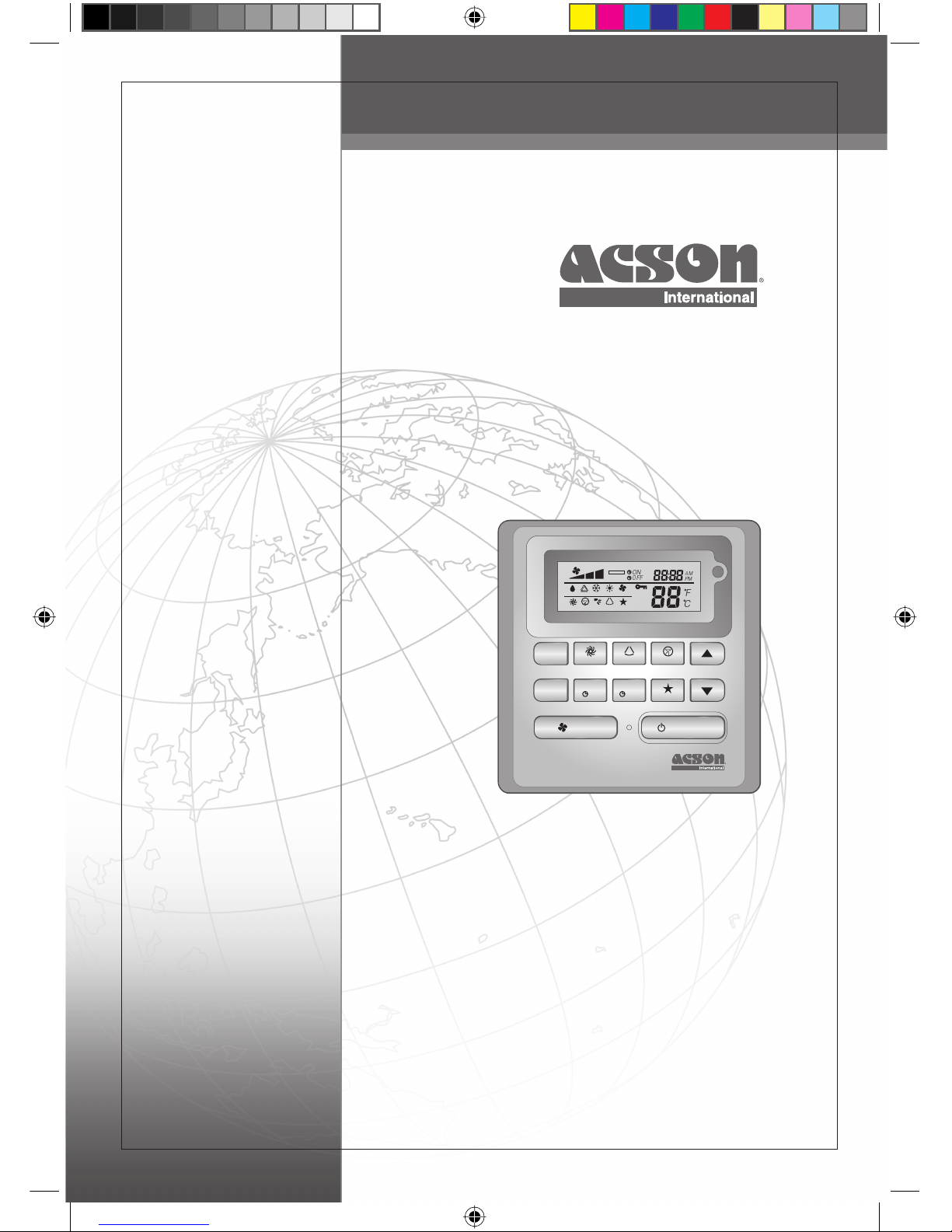
OPERATION MANUAL
Before using your air conditioner, please read this operating
manual carefully and keep it for future reference.
OM-SLM9-0211(0)-Acson
Part No.: R08019036117
MODE
TURBO
DELAY
TIMER
TIMER
ON OFF
TIMER
FAN ON / OFF
SWING QUIET
SLEEP
MON
AUTO
OVERRIDE
TUE WED THU
ROOM
TEMP.
SET
TEMP.
FRI SAT SUN ALL
12
12
12
DRY
TURBO QUIET
SWING
SLEEP
AUTO COOL HEAT FAN
AM
ON
OFF
PM
F
C
CVR-OM-SLM9-0211(0)AC.indd 1CVR-OM-SLM9-0211(0)AC.indd 1 10/20/11 8:33:31 AM10/20/11 8:33:31 AM
Page 2
i
MODE
TURBO
DELAY
TIMER
TIMER
ON OFF
TIMER
FAN ON / OFF
SWING QUIET
SLEEP
MON
AUTO
OVERRIDE
TUE WED THU
ROOM
TEMP.
SET
TEMP.
FRI SAT SUN ALL
12
12
12
DRY
TURBO QUIET
SWING
SLEEP
AUTO COOL HEAT FAN
AM
ON
OFF
PM
F
C
1
4
5
6
7
2
3
12
13
10
9
11
8
NO KEY FUNCTION
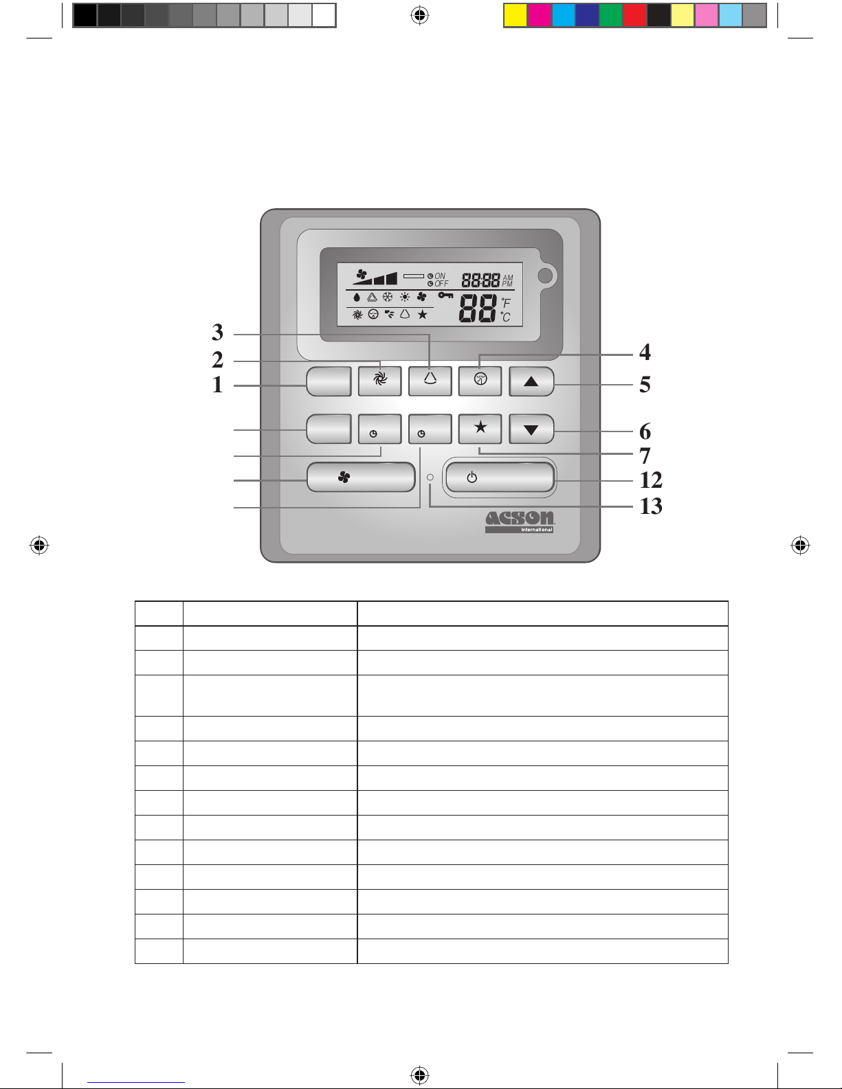
1. MODE Select operating Modes control (Cool/ Heat/ Auto/ Dry/ Fan)
2. TURBO Activate/deactivate Turbo function
3. SWING Activate/deactivate Swing control
Hold Key to change Swing Mode
4. QUIET Activate/deactivate Quiet function
5. SET TEMP UP Increase set temperature in °C or °F
6. SET TEMP DOWN Decrease set temperature in °C or °F
7. SLEEP Activate/deactivate Sleep function
8. OFF TIMER Enable/disable the Event 1 and 2 OFF TIMER setting mode
9. ON TIMER Enable/disable the Event 1 and 2 ON TIMER setting mode
10. DELAY TIMER Activate/deactivate delay timer
11. FAN Select Fan speeds control (Auto/ High/ Med/ Low)
12. ON/OFF On/Off the unit with overriding all the timer settings
13. REAL TIME CLOCK (RTC) Enable/disable the Real Time Clock (RTC) setting mode
NOTE:
Turbo and quiet function are for selected models only.
SLM9 Controller Indication
INDD-OM-SLM9-0211(0)AC.indd iINDD-OM-SLM9-0211(0)AC.indd i 10/20/11 8:33:46 AM10/20/11 8:33:46 AM
Page 3
ENGLISH
1
1.1 MODE Button
Press the MODE button to switch operation from COOL, HEAT*, AUTO*, DRY*, FAN. Check the
display to see in which mode the control is set. *HEAT, AUTO and DRY are available for selected
models only.
1.2 TURBO Fan Speed
Press the TURBO key once to activate Turbo fan speed. Turbo symbol will be shown. To disable Turbo
fan speed and back to previous fan speed, press the Turbo key once again. If user presses the FAN
button or QUIET button or turn off the unit, the turbo speed will be disabled. This speed is only valid
during COOL and HEAT mode for selected models.
1.3 Automatic air swing
Press the SWING button to activate the automatic air swing function.
To distribute the air to a specific direction, press the SWING button and wait until the louver
move to the desired direction and press the button once again.
Swing mode selection method (for CK-E model)
Press SWING ( ) button for 4 seconds to enter field setting mode. While in field setting mode, it
will only show SWING MODE ( ).
Press temperature and button to select SWING MODE ( ) rotation from Swing Mode 1 to
Swing Mode 3.
There are 3 different SWING MODE, which are:
Swing mode 1 Swing mode 2 Swing mode 3
SWING MODE will not activate unless SWING is activated.
Swing is indicated by the logo:
If no mode changes within 4 seconds, unit will operate according to the selected SWING MODE ( ).
1.4 QUIET Fan Speed
Press the QUIET key once to activate Quiet fan speed. QUIET symbol will be shown. To disable Quiet
fan speed and back to previous fan speed, press the QUIET key again. If user presses the FAN button
or TURBO button or turn off the unit, the quiet speed will be disabled. This speed is only valid during
COOL and HEAT mode for selected models.
1.5 “ ” or “ ” Set Temperature Button
Press the temperature button and set the temperature of your choice by pressing “ ” or “ ” button
once, temperature changes by 1°C or 1°F. The default temperature setting range is from 16°C to 30°C
(60°F to 86°F). When the Option 20 - 30ºC is set, the temperature range limit is set to 20ºC to 30ºC
(68°F to 86°F). Pressing both keys simultaneously will toggle the temperature setting between ºC
and ºF. No temperature setting is allowed during FAN mode (No set temp display). There is no room
temperature display.
1.6 SLEEP Function
Press the SLEEP button to activate the sleep mode. SLEEP function is not available in DRY mode
and FAN mode.
1.7 “ON TIMER” and “OFF TIMER”
The unit has 2-event timer, namely Timer 1 and Timer 2, each event has an ON TIMER and an OFF
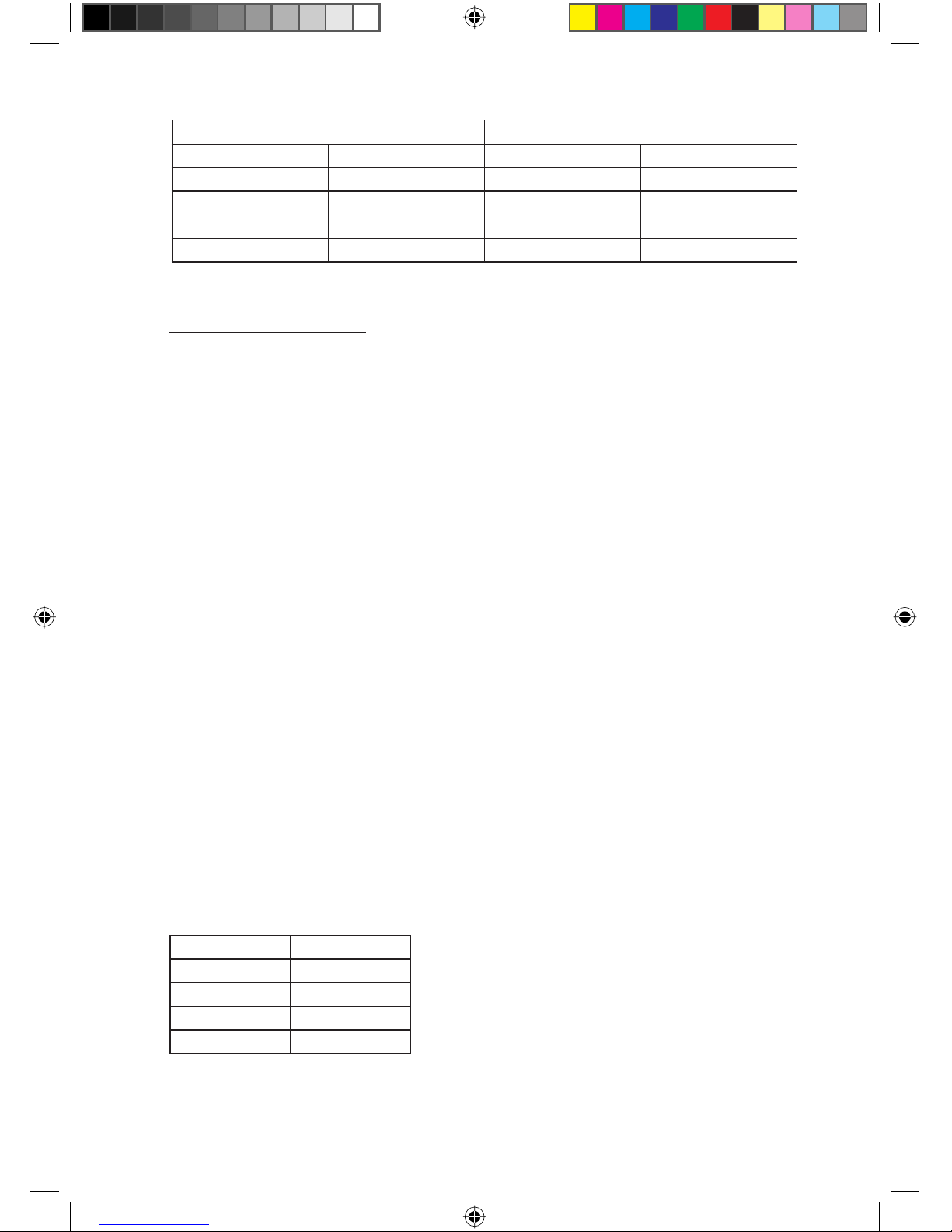
TIMER. The key press activity for Timer ON and Timer OFF is shown on Table 1.1
•
•
•
•
•
•
OPERATING INSTRUCTION
Original Instruction
INDD-OM-SLM9-0211(0)AC.indd 1INDD-OM-SLM9-0211(0)AC.indd 1 10/20/11 8:33:47 AM10/20/11 8:33:47 AM
Page 4
2
Table 1.1: Timer ON and Timer OFF key press and event sequence.
TIMER ON KEY TIMER OFF KEY
ON Timer 1 ON Timer 2 OFF Timer 1 OFF Timer 2
Deactivated Deactivated Deactivated Deactivated
Activated Deactivated Activated Deactivated
Deactivated Activated Deactivated Activated
Activated Activated Activated Activated
All timers are event-triggered timers and can be overridden by the ON/OFF button and Override
function.
Set Event 1 and Event 2 Timers
Process for Timer ON and Timer OFF is the same.
Press and hold Timer ON/OFF key for 3 seconds to go into timer setting mode.
(Icon ON 1 or OFF 1 will blink)
Press UP or DOWN to select Timer 1 or Timer 2 to set.
(‘1’ blinking indicate that Timer 1 is currently selected, ‘2’ blinking indicate that Timer 2 is currently
selected)
Press Timer ON/OFF key again to confirm. (Day will blink next)
Press UP or DOWN to select the day.
Press Timer ON/OFF key again to confirm the day. (Hour will blink next)
Press UP or DOWN to change the hour.
Press Timer ON/OFF key again to confirm the hour. (Minute will blink next)
Press UP or DOWN to change the minute.
Press Timer ON/OFF key again to confirm the minute.
Each timer (Timer 1 ON or Timer 1 OFF or Timer 2 ON or Timer 2 OFF) will only be set separately
after all 7 steps, if there is no key operation for 5 seconds during setting the timer, it will automatically
exits from setting mode and no changes will be made.
ON/OFF timer will be checked every 1 minute.
It is not advisable to set ON TIMER and OFF TIMER to have same values. Shall these occur, the
effective timer will be treated with priority as stated in Table 1.2.
Example:
ON TMR 2 settings: DAY – TUE, TIMER – 5.00pm
OFF TMR 1 settings: DAY – TUE, TIMER – 5.00pm
Outcome when RTC reaches 5.00pm on TUE:
when unit is on, no respond.
when unit is off, unit will trigger to on.
Table 1.2: Timer Priority
Priority Timer
1 (Highest) ONTMR2
2 OFFTMR2
3 ONTMR1
4 (Lowest) OFFTMR1
Upon IR reception, IR wireless remote controller will override ON TIMER 2 and OFF TIMER 2
settings.
1.
2.
3.
4.
5.
6.
7.
8.
9.
–
–
INDD-OM-SLM9-0211(0)AC.indd 2INDD-OM-SLM9-0211(0)AC.indd 2 10/20/11 8:33:47 AM10/20/11 8:33:47 AM
Page 5

ENGLISH
3
1.8 DELAY TIMER Function
Press the D
ELAY TIMER key once will activate the delay timer function for 1 hour. An indicator
“OVERRIDE” will show on the LCD. Press the same key again will increase the setting to 2 hours.
An indicator “OVERRIDE” will be shown. Subsequent press will deactivate the delay timer function.
After the delay timer is completed, the delay timer function is deactivated and the logo is OFF. All
other timers will be r
esumed.
1.9 FAN Speed Function
Fan speed can be changed via pressing the FAN key:
Low > Med > High > Auto >
*FAN speed is not available in DRY mode.
1.10 ON/OFF Button
Starting Operation:
Press the ON/OFF button, the LCD will show full display and the unit is turned on.
Stopping Operation:
Press the ON/OFF button, the LCD will show real time clock only and the unit is turn off.
1.11 Power up Settings
The unit will start up with main board’s last state setting during power up. If last state information is
not available, the unit will use the default settings. The default settings are as below:
Unit: Off
Mode: Cool
Fan Speed: High
RTC: 12:00AM, MONDAY
Swing: Off
Swing Mode: Standard
Timers: Disable
Turbo: Disable
Quiet: Off
Sleep: Off
Override: Disable
1.12 Real-time Clock (RTC) Display
RTC is shown on screen during the unit ON or OFF except for power failure or error code.
Set RTC Setting
Press RTC key one time will activate RTC setting mode. (Day will blink)
Press UP or DOWN to select the day.
Press RTC again to confirm the day. (Hour will blink next)
Press UP or DOWN to change the hour.
Press RTC again to confirm the hour. (Minute will blink next)
Press UP or DOWN to change the minute.
Press RTC again to confirm the minute.
RTC will only be set after all 7 steps, if there is no key operation for 5 seconds during setting the RTC,
it will automatically exits from setting mode and no changes will be made on the setting.
1.13 Key Lock
These key lock function inhibits any setting change. Press and hold both TURBO and QUIET keys
for 5 seconds will activate/deactivate the key lock function; “KEYLOCK” will be shown/disappear on
LCD. Upon all the keys are locked, only ON/OFF, TURBO and QUIET (to unlock) can be pressed.
–
–
1.
2.
3.
4.
5.
6.
7.
INDD-OM-SLM9-0211(0)AC.indd 3INDD-OM-SLM9-0211(0)AC.indd 3 10/20/11 8:33:48 AM10/20/11 8:33:48 AM
Page 6
4
1.14 Battery Backup
Battery backup is used to retain the RTC and 7-days programmable timer settings during power down
for a minimum of 1 month continuous for every new set of battery installed. For unit without battery
backup, the default setting will be 12:00am on Monday and timer clear during power up.
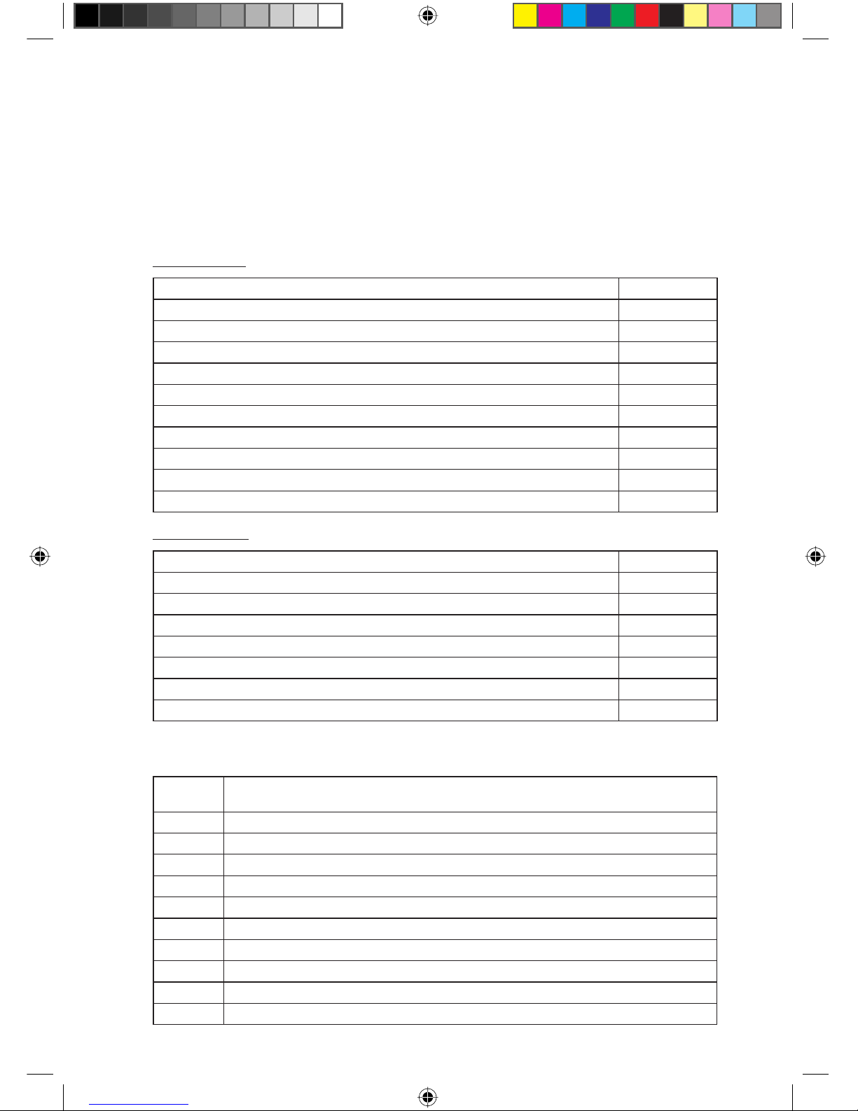
1.15 Error Indicator
If any abnormal condition detected, an error code will be shown. Error code is displayed by using RTC
segments (blink), which mean whenever there is error occur, RTC will not be shown instead of the error
code. The format for the error code will be as following:
DX Error Code
Error Description
Room Sensor Open or Short E1
Indoor Coil Sensor Open E2
Outdoor Coil Sensor Open E3
Compressor Overload/Indoor Coil Sensor Short/Outdoor Coil Sensor Short E4
Gas Leak E5
Water Pump Fault E6
Outdoor Coil Sensor Exist (MS model) E7
Hardware Error (Tact Switch Pin Short) E8
Indoor Fan Feedback Error E9
EEPROM Error EE
CW Error Code
Error Description
Room Sensor Open or Short E1
Pipe Water Sensor Open or Short E2
Pipe Water Temperature Poor E4
Pipe Water Temperature Bad/Fault E5
Water Pump Error E6
Hardware Error (Tact Switch Pin Short) E8
Indoor Fan Feedback Error E9
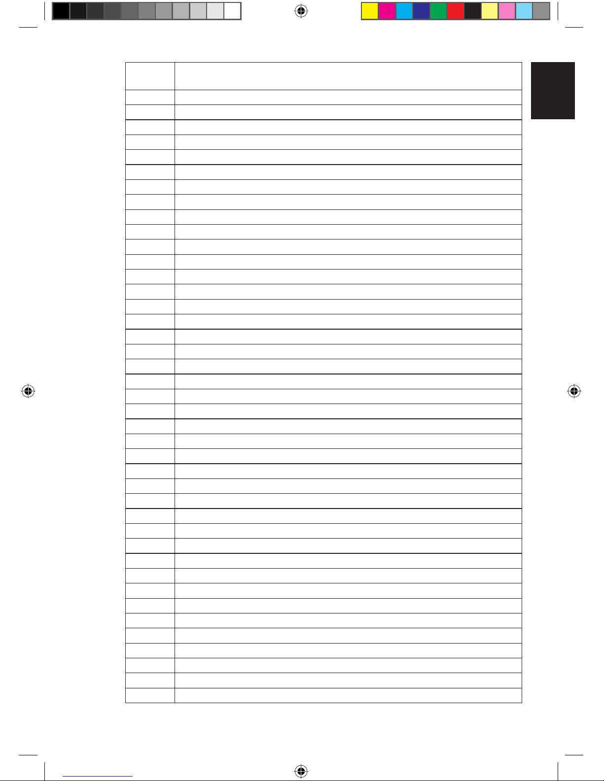
Fault Diagnosis (for inverter only)
If there is any abnormal condition detected, SLM9 wired controller will blink the error code
ERROR
CODE
MEANING
00 NORMAL
A1 INDOOR PCB ERROR
A3 DRAIN PUMP ABNORMAL
A5 ANTIFREEZE (COOLING)/HEAT EXCHANGER OVERHEAT (HEATING)
A6 INDOOR FAN MOTOR ABNORMAL
AH ELECTRICAL AIR CLEANER ABNORMAL
C4 INDOOR HEAT EXCHANGER (1) THERMISTOR SHORT/OPEN
C5 INDOOR HEAT EXCHANGER (2) THERMISTOR SHORT/OPEN
C7 LOUVER LIMIT SWITCH ERROR
C9 INDOOR ROOM THERMISTOR SHORT/OPEN
INDD-OM-SLM9-0211(0)AC.indd 4INDD-OM-SLM9-0211(0)AC.indd 4 10/20/11 8:33:48 AM10/20/11 8:33:48 AM
Page 7
ENGLISH
5
ERROR
CODE
MEANING
E1 OUTDOOR PCB ERROR
E3 HIGH PRESSURE PROTECTION
E4 LOW PRESSURE PROTECTION
E5 COMPRESSOR MOTOR LOCK/COMPRESSOR OVERLOADED
E6 COMPRESSOR START-UP ERROR
E7 OUTDOOR DC FAN MOTOR LOCK
E8 AC INPUT OVER CURRENT
E9 EXV ERROR
EA 4 WAY VALVE ERROR
F3 DISCHARGE PIPE OVERHEAT
F6 HEAT EXCHANGER OVERHEAT
HO COMPRESSOR SENSOR SYSTEM ERROR
H3 HIGH PRESSURE SWITCH ERROR
H6 COMPRESSOR FEEDBACK DETECTION ERROR
H7 FAN MOTOR OVERLOADED/OVERCURRENT/SENSOR ABNORMAL
H8 AC CURRENT SENSOR ERROR
H9 OUTDOOR AIR THERMISTOR SHORT/OPEN
J1 PRESSURE SENSOR ERROR
J3
COMPRESSOR DISCHARGE PIPE THERMISTOR SHORT/OPEN/MISPLACED
J5 SUCTION PIPE THERMISTOR SHORT/OPEN
J6 OUTDOOR HEAT EXCHANGER THERMISTOR SHORT/OPEN
J7 SUBCOOLING HEAT EXCHANGER THERMISTOR SHORT/OPEN
J8 LIQUID PIPE THERMISTOR SHORT/OPEN
J9 GAS PIPE THERMISTOR SHORT/OPEN
L1 INVERTER OUTDOOR PCB ERROR
L3 OUTDOOR CONTROL BOX OVERHEAT
L4 HEAT SINK OVERHEAT
L5 IPM ERROR/IGBT ERROR
L8 INVERTER COMPRESSOR OVERCURRENT
L9 COMPRESSOR OVERCURRENT PREVENTION
LC
COMMUNICATION ERROR (OUTDOOR CONTROL PCB AND INVERTER PCB)
P1 OPEN PHASE OR VOLTAGE UNBALANCE
P4 HEAT SINK THERMISTOR SHORT/OPEN
PJ CAPACITY SETTING ERROR
U0 INSUFFICIENT GAS
U2 DC VOLTAGE OUT OF RANGE
U4 COMMUNICATION ERROR
U7 COMMUNICATION ERROR (OUTDOOR CONTROL PCB AND IPM PCB)
UA INSTALLATION ERROR
UF
PIPING & WIRING INSTALLATION MISMATCH/WRONG WIRING/INSUFFICIENT GAS
UH ANTIFREEZE (OTHER ROOMS)
INDD-OM-SLM9-0211(0)AC.indd 5INDD-OM-SLM9-0211(0)AC.indd 5 10/20/11 8:33:48 AM10/20/11 8:33:48 AM
Page 8
6
2. HARDWARE SETTING
The unit has 2 jumpers option to control the board function.
Table 2.0: Summary of Hardware Settings
OPTION With Jumper Without Jumper
Set Temp. Range Set temp. range from 20°C – 30°C
Set temp. range from 16°C – 30°C
(Default)
TURBO_QUIET
Disable turbo and quiet fan speed
(Default)
Enable turbo and quiet fan speed
* Only applicable to model with built in Turbo or Quiet features.
3.0 INSTALLATION
3.1 Accessories
The following accessories are included together with this manual. If any part is missing, contact your
dealer immediately.
Remote controller
Wooden screw (2 pieces) & machine screw (2 pieces)
Instruction manual
Battery
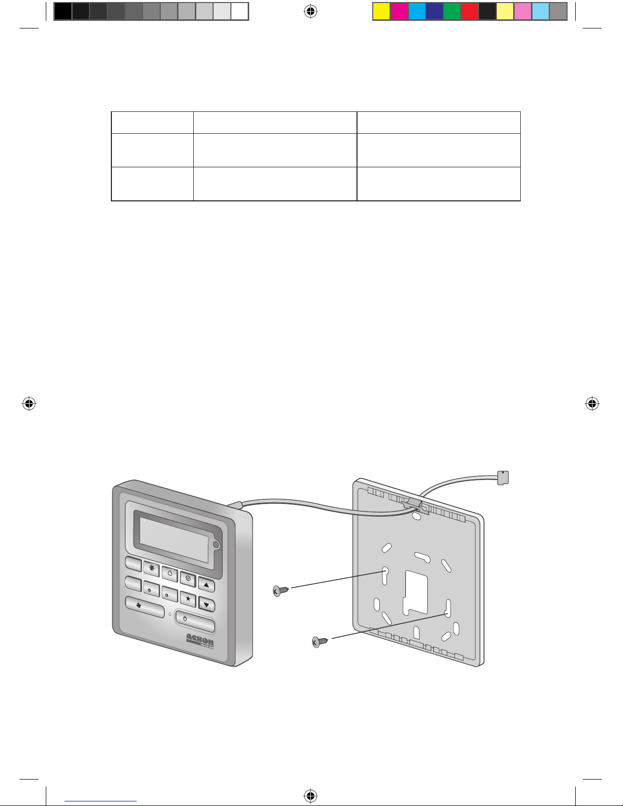
3.2 Step-by-step guide
Open the clip on the top of the controller first follow by the bottom clip. Remove the top case of
the controller from the bottom case.
Fix the bottom case to the wall with the 2 screw provided. Then insert the connection wire through
the slot on the upper center case as shown.
Insert back the bottom clip first then snap the upper part shut.
MO
DE
TURBO
D
ELAY
T
IMER
T
IMER
ON OFF
TIMER
F
A
N ON / OFF
S
W
I
N
GQU
I
E
T
S
LEE
P
LCD Remote
(Top case)
Connection
wires
2 x Wooden
screw
LCD Remote
(Bottom case)
1.
2.
3.
4.
I.
II.
III.
INDD-OM-SLM9-0211(0)AC.indd 6INDD-OM-SLM9-0211(0)AC.indd 6 10/20/11 8:33:48 AM10/20/11 8:33:48 AM
Page 9

MEMO
INDD-OM-SLM9-0211(0)AC.indd 7INDD-OM-SLM9-0211(0)AC.indd 7 10/20/11 8:33:48 AM10/20/11 8:33:48 AM
Page 10

MEMO
INDD-OM-SLM9-0211(0)AC.indd 8INDD-OM-SLM9-0211(0)AC.indd 8 10/20/11 8:33:48 AM10/20/11 8:33:48 AM
Page 11

CVR-OM-SLM9-0211(0)AC.indd 2CVR-OM-SLM9-0211(0)AC.indd 2 10/20/11 8:33:31 AM10/20/11 8:33:31 AM
Page 12

• In the event that there is any confl ict in the interpretation of this manual and any translation of the same in any language,
the English version of this manual shall prevail.
• The manufacturer reserves the right to revise any of the specifi cation and design contain herein at any time without prior
notifi cation.
• En cas de désaccord sur l’interprétation de ce manuel ou une de ses traductions, la version anglaise fera autorité.
• Le fabriquant se réserve le droit de modifi er à tout moment et sans préavis la conception et les caractéristiques techniques
des appareils présentés dans ce manuel.
• Im Falle einer widersprüchlichen Auslegung der vorliegenden Anleitung bzw. einer ihrer Übersetzungen gilt die Ausführung
in Englisch.
• Änderungen von Design und technischen Merkmalen der in dieser Anleitung beschriebenen Geräte bleiben dem Hersteller
jederzeit vorbehalten.
• Nel caso ci fossero confl itti nell’interpretazione di questo manuale o delle sue stesse traduzioni in altre lingue, la versione
in lingua inglese prevale.
• Il fabbricante mantiene il diritto di cambiare qualsiasi specifi cazione e disegno contenuti qui senza precedente notifi ca.
• En caso de confl icto en la interpretación de este manual, y en su traducción a cualquier idioma, prevalecerá la versión
inglesa.
• El fabricante se reserva el derecho a modifi car cualquiera de las especifi caciones y diseños contenidos en el presente
manual en cualquier momento y sin notifi cación previa.
• В случае противоречия перевода данного руководства с другими переводами одного и того же текста,
английский вариант рассматривается как приоритетный.
• Завод-изготовитель оставляет за собой право изменять характеристики и конструкцию в любое время
без предварительного уведомления.
• Bu k›lavuzun anlafl›lmas›nda bir çat›flma oldu¤unda ve farkl› dillerdeki tercümeler farkl›l›k gösterdi¤inde, bu
k›lavuzun ‹ngilizce sürümü üstün tutulacakt›r.
• Üretici burada bulunan herhangi teknik özellikleri ve tasar›mlar› herhangi bir zamanda ve önceden haber
vermeden de¤ifltirme hakk›n› sakl› tutar.
OYL MANUFACTURING COMPANY SDN. BHD.
LOT 60334, PERSIARAN BUKIT RAHMAN PUTRA 3, TAMAN PERINDUSTRIAN BUKIT RAHMAN PUTRA,
47000 SUNGAI BULOH, SELANGOR DARUL EHSAN, MALAYSIA.
CVR-OM-SLM9-0211(0)AC.indd 3CVR-OM-SLM9-0211(0)AC.indd 3 10/20/11 8:33:31 AM10/20/11 8:33:31 AM
 Loading...