


Wall Mounted Split Systems
AWM - G - 2007
AWM 07G/GR
AWM 09G/GR
AWM 10G/GR
AWM 15G/GR
AWM 20G/GR
AWM 25G/GR
AWM 301/301R
A5WM 07G/GR
A5WM 09G/GR
A5WM 10G/GR
A5WM 15G/GR
A5WM 20G/GR
A5WM 25G/GR
A5WM 311/301R
Models:
Downloaded from AC-Manual.com Manuals

TABLE OF CONTENTS
1. NOMENECLATURE ................................................................................................... 1
- PRODUCT LINE-UP ............................................................................................ 3
2. FEATURES ................................................................................................................ 7
3. APPLICATION INFORMATION
- OPERATING RANGE .......................................................................................... 9
- REFRIGERANT CIRCUIT DIAGRAMS .............................................................. 10
- CONTROLLERS ................................................................................................. 17
- INSTALLATION .................................................................................................. 25
4. SOUND DATA ........................................................................................................... 39
5. ENGINEERING AND PHYSICAL DATA
- GENERAL DATA ................................................................................................ 43
- COMPONENTS DATA ........................................................................................ 59
6. PERFORMANCE DATA ............................................................................................ 75
- PERFORMANCE TABLES ................................................................................. 79
7. DIMENSIONAL DATA............................................................................................... 106
8. ELECTRICAL DATA ................................................................................................. 110
9. WIRING DIAGRAMS ................................................................................................ 118
10. SERVICING AND MAINTENANCE ........................................................................ 127
11. TROUBLESHOOTING ........................................................................................... 129
12. EXPLODED VIEW & PARTS LIST ........................................................................ 134
Downloaded from AC-Manual.com Manuals

1
1. NOMENCLATURE
A
WM 10 G
R
Brand
A : ACSON
Capacity
10 : 9,500 Btu/h
Series
G : G series
Model Type
R : Heatpump
Omitted if Cooling Only
I A
A
C A-
Refrigerant
5 : R410A
Omitted if R22
Model Name
WM : Wall Mounted
Electrical
A : 220 - 240V/1Ph/50Hz
Others
A : First issue
Grille Type
A : Grille A
Market Region
C : Export with CE mark
U : UTL Spec.
Air Treatment Devices & Control
I : Negative Ion with wireless controller
N : NTP with wireless controller
X : Oxygen unit
Indoor
Downloaded from AC-Manual.com Manuals

2
A LC 10 C
R
Brand
A : ACSON
Capacity
10 : 9,500 Btu/h
Series
C : C series
Model Type
R : Heatpump
Omitted if Cooling Only
5 P O
A
C A-
Model Name
LC : Single Split Condensing Unit
Electrical
A : 220 - 240V/1Ph/50Hz
Others
A : First issue
Outdoor
Compressor
P : Matsushita Rotary T : Toshiba Rotary
M : Mitsubishi Rotary S : Samsung Rotary
Specification Variation
O : Standard Unit I : Gold Fins
B : With Contactor L : Long Piping Unit
G : Low Ambient Kit S : With H/L Pressure Switch
H : High Ambient Kit X : Oxygen Unit
Market Region
C : Export with CE marking
E : Export without marking
U : ETL Spec.
Refrigerant
5 : R410A
Omitted if R22 Model
Downloaded from AC-Manual.com Manuals

3
INDOOR UNIT
AWM-G SERIES PRODUCT LINE UP
Product Line Up
AWM
Marking
Grille
07GACIADX X XX XX
09GACIACX X XX XX
10GACIACX X XX XX
15GACIACX X XX XX
20GACIACX X XX XX
25GACIACX X XX XX
30FAFDBXXXX XX
07GRACIACX X XX XX
09GRACIACX X XX XX
10GRACIACX X XX XX
15GRACIACX X XX XX
20GRACIACX X XX XX
25GRACIACX X XX XX
30FR AFCA X X X X X
CE
O2 Theraphy
A
Cooling Model
Saranet Filter
Ionizer Filter
Heatpump Model
L2.0
G12
Nomenclature
PCB Air Purification
Nano Technology Air Filteration
Negative Ion
CLASSIFICATIONS
Orifice Kit
U1.5
Non-Thermal Plasma (NTP)
Handset
G12 (W/O Turbo mode)
D2.0
Downloaded from AC-Manual.com Manuals

4
INDOOR UNIT
A5WM-G SERIES PRODUCT LINE UP
A5WM
Marking
Grille
07G ACIAC X X X X X X
09G ACIAC X X X X X X
10G ACIAC X X X X X X
15G ACIAC X X X X X X
20G ACIAC X X X X X X
25G ACIAC X X X X X X
311 AFCA X X X X X X
07GR ACIAC X X X X X X
09GR ACIAC X X X X X X
10GR ACIAC X X X X X X
15GR ACIAC X X X X X X
20GR ACIAC X X X X X X
25GR ACIAC X X X X X X
301R AFCA X X X X X X
PCB Air Purification
Cooling ModelHeatpump Model
B
Nano Technology Air Filteration
Non-Thermal Plasma (NTP)
CE
Ionizer Filter
Saranet Filter
Negative Ion
CLASSIFICATIONS
Nomenclature
Handset
G12
G12 (W/O Turbo mode)
L2.0
D2.0
Downloaded from AC-Manual.com Manuals

5
OUTDOOR UNIT
ALC PRODUCT LINE UP
ALC
Compressor
Cap. Tube
7mm Coil
3/8" Coil
Gold Fin
W/O Contactor
Contactor
Rotary Comp.
W/O Marking
CE Marking
ETL
Thai
HK
Singapore
ACPOE X X X X X
ACPIEXXXXXX
ACPOD X X X X
ACPIDXXX XX
ACPOB X X X X
ACPIBXXX XX
ACPOD X X X X
ACPIDXXX XX
ATPO D X X X X X X
ACPOD X X X X
ACPIDXXX XX
ACPBD X X X X X X X
ACPOD X X X X
ACPIDXXX XX
ACPBD X X X X X X X
ATPO D X X X X X
ACPBD X X X X X
ACPOD X X X X
ACPIDXXX XX
ACPOD X X X X
ACPIDXXX XX
ACPBD X X X X X X X
ACPOD X X X X
ACPIDXXX XX
ACPBD X X X X X X X
ACPBD X X X X X
ACPOD X X X X
ACPIDXXX XX
20CR
25CR
Marking Market
Cooling Model
07C
09C
10C
15C
18C
20C
Nomenclature
Refrigerant Ctrl + Fin
Safety
Devices
Heatpump Model
CLASSIFICATIONS
25C
18CR
Downloaded from AC-Manual.com Manuals

6
OUTDOOR UNIT
A5LC PRODUCT LINE UP
A5LC
Compressor
Marking Others
Cap. Tube
Gold Fin
Contactor
HP
LP
Mat. Rotary
CE Marking
Drain Elbow
07C ACPOE X X X
10C ACPOB X X X
15C ACPOC X X X
20C ACPOC X X X
25C ACPOC X X X
28C ACPOA X X X
07CR ACPOE X X X X
10CR ACPOB X X X X
15CR ACPOC X X X X
20CR ACPOC X X X X
25CR ACPOC X X X X
28CR ACPOA X X X X
Heatpump Model
Safety Devices
Refri
g
erant
Ctrl + Fin
Nomenclature
CLASSIFICATIONS
Cooling Model
Downloaded from AC-Manual.com Manuals

7
2. FEATURES
• EASY INSTALLATION
- The wall mounted fan coil unit is easily installed because of its compact size, slimness and light weight.
- Slim and short outdoor unit can be easily installed even in a narrow balcony and passageway and yet
have a stable profile.
• SPACE SAVING
- No space is required on either floor or ceiling. This newly developed super slim design for wall mounting
maximizes floor space usage and enhances ceiling appearance where ceilings are low.
• QUIET OPERATION
- Cooling comfort is improved by whisper-quiet operation which is achieved by a tangential fan.
• EXCELLENT AIR DISTRIBUTION
- Air discharge direction can be adjusted in four directions, manually or automatically by using LCD
remote control.
- The new double louver design with automatic air swing function fully optimizes the room comfort by
distributing the air evenly to the room.
- The unique skew fan design with larger diameter creates better air flow to the operating environment.
• FACILITATED MAINTENANCE ENSURED
- The new design of air discharge housing whereby the fan blower can be easily accessed by just loosing
two screws on the unit to provides a flexible, faster and easier way to clean up the fan blower and
ionizer.
- Maintenance is easy for electrical components, piping and wiring as these are all easily accessible by
merely removing front plastic panel.
• WIRELESS REMOTE CONTROL
- The compact LCD transmitter is able to operate the air conditioner unit within the distance of 9 meters.
- Fan motor speed can be set at low/medium/high or automatic.
- Sleep mode auto control will gradually increase or decrease the setting temperature to provide a
comfortable surrounding for sleeping.
- Air flow direction can be controlled automatically.
- Room temperature is controlled by electronic thermostat.
- The real time timer allows the air conditioner to be switched On and Off automatically based on user
settings.
- Turbo mode function is available to enables the required set temperature to be achieved in a short time.
- Ionizer or non-thermal plasma is available to create better air quality.
- Personalized Setting allows user to preset and store 2 groups of personal settings (including timer
setting) in the handset.
- Auto random restart is a function whereby when there is power failure occurred during operation, the
unit will automatically restart as the last setting condition once the power is resumed.
••
••
• MOISTURE REMOVAL
- Dry mode with super low indoor fan speed can achieve more affective moisture removal.
- If the room temperature is lower than the set temperature (Cooling mode only), the compressor will cut
out and force on after 9 minutes to remove moisture effectively.
Downloaded from AC-Manual.com Manuals

8
• HIGH EFFICIENCY HEAT EXCHANGER
- The compact design of the 3-fold structure heat exchanger provides a large surface are for better and
efficient heat exchange.
- The unique Hydrophilic slit fin has greatly improved the air flow and the contact surfaces with the air thus
to boost the cooling capacity.
• ROTARY COMPRESSOR
- The ever popular rotary compressor is more energy efficient and has a higher output to weight ratio.
• SELF DIAGNOSIS
- This function is able to detect and to diagnose any faults occurring in the system by blinking of the LED
lights.
- Simplify and ease for troubleshooting.
Downloaded from AC-Manual.com Manuals

9
3. APPLICATION INFORMATION
Operating Range
Ensure the operating temperature is in allowable range.
Cooling only
Heatpump
Caution :
The use of your air conditioner
outside the range of working
temperature and humidity can
result in serious failure.
Coolin
g
Outdoor temp. (°CDB)
Indoor temp. (°CWB
)
0
19
35
15
46
24
54
STD
HIGH AMBIENT
UNIT
LOW AMBIENT
KIT
Heatin
g
Outdoor temp. (°CWB)
Indoor temp. (°CDB
)
-9
15 21
6
27
18
STD
Coolin
g
Outdoor temp. (°CDB)
Indoor temp. (°CWB
)
0
19
35
15
46
24
54
STD
HIGH AMBIENT
UNIT
LOW AMBIENT
KIT
Downloaded from AC-Manual.com Manuals

10
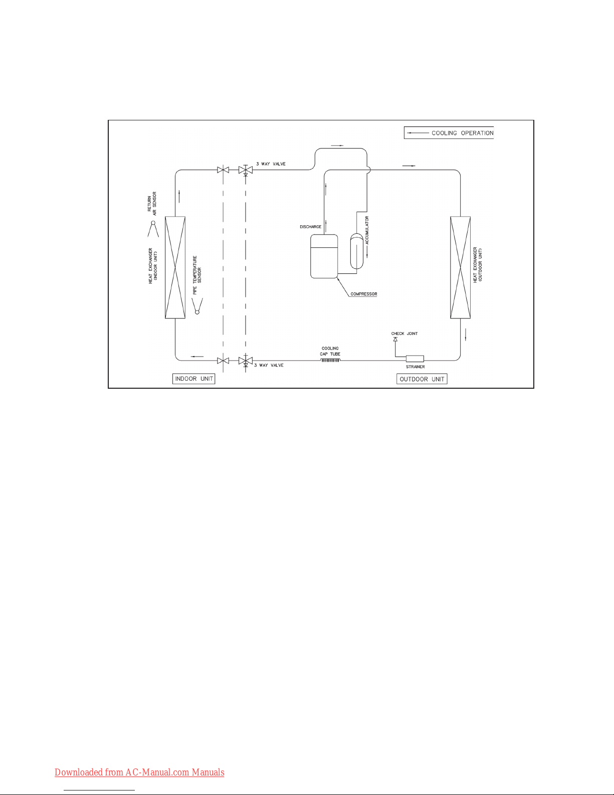
Refrigerant Circuit Diagram
Cooling Only Models
MODEL : AWM 07G - ALC 07C A5WM 07G - A5LC 07C
AWM 09G - ALC 09C A5WM 09G - A5LC 10C
AWM 10G - ALC 10C A5WM 10G - A5LC 10C
AWM 15G - ALC 15C A5WM 15G - A5LC 15C
Downloaded from AC-Manual.com Manuals

11
Cooling Only Models
MODEL : AWM 20G - ALC 18C A5WM 20G - A5LC 20C
AWM 20G - ALC 20C A5WM 25G - A5LC 25C
MODEL : AWM 25G - ALC 25C A5WM 31F - A5LC 28C
Downloaded from AC-Manual.com Manuals
12
Cooling Only Models
MODEL : AWM 30F - ALC 28C
Downloaded from AC-Manual.com Manuals

13
Heatpump Models
MODEL : AWM 09GR - ALC 09CR A5WM 07GR - A5LC 07CR
MODEL : AWM 10GR - ALC 10CR
A5WM 09GR - A5LC 10CR A5WM 10GR - A5LC 10CR
Downloaded from AC-Manual.com Manuals

14
Heatpump Models
MODEL : AWM 15GR - ALC 15CR A5WM 15GR - A5LC 15CR
Downloaded from AC-Manual.com Manuals

15
Heatpump Models
MODEL : AWM 20GR - ALC 20CR A5WM 20GR - A5LC 20CR
A5WM 25GR - A5LC 25CR
MODEL : AWM 25GR - ALC 25CR
Downloaded from AC-Manual.com Manuals

16
Heatpump Models
MODEL : AWM 30FR - ALC 28CR A5WM 30FR - A5LC 28CR
Downloaded from AC-Manual.com Manuals

17
Controllers
G12 Remote Controller
Temperature Setting
• To set the desired room
temperature, press the button to
increase or decrease the set
temperature.
• The temperature setting range is
from 16°C to 30°C
• Press both buttons simultaneously
to toggle the temperature setting
between °C and °F
Turbo Mode
• Press the TURBO button to
achieve the required set
temperature in a short time.
ON Timer Setting
• Press the SET button will activate
the on timer function.
• Set the desired on time by pressing
the SET button continuously.
• Press the CLR button to cancel the
off timer setting
Sleep Mode
• Press the button to activate sleep
mode. This function is available
under COOL, HEAT & AUTO
mode.
• When it is activated in COOL
mode, the set temperature will be
increased 0.5°C after 30mins, 1°C
after 1 hour and 2°C after 2 hours.
• When it is activated in HEAT
mode, the set temperature will be
decreased 1°C after 30mins, 2°C
after 1 hour and 3°C after 2 hours.
Personalised Setting
• Press and hold the button for 3s to
initiate personalized setting.
• Set the individual setting e.g.
MODE, SET TEMP or FAN SPEED
and leave for 4s to save
• 2 groups of settings are allowed to
stored in the handset
Fan Speed Selection
• Press the button until the desired
fan speed is achieved.
Operating Mode
• Press the MODE button to select
the type of operating mode.
• For Cooling only unit, the available
modes are: COOL, DRY & FAN.
• For Heatpump unit, the available
modes are: AUTO, COOL, DRY,
FAN & HEAT.
OFF Timer Setting
• Press the SET button will activate
the off timer function.
• Set the desired off time by
pressing the SET button
continuously.
• Press the CLR button to cancel the
off timer setting
Automatic Air Awing
• Press the SWING button to activate
the automatic air swing function.
• To distribute the air to a specific
direction, press the SWING button
and wait until the louver move to
the desired direction and press the
button once again.
On/Off Button
• Press Once to start the air
conditioner
• Press again to stop the unit
Clock Time Setting
• Press button + or - to increase or
decrease the clock time.
Ionizer
• Press the button to activate the
negative Ion function, which will
refresh the indoor air effectively.
Downloaded from AC-Manual.com Manuals

18
Indicator Lights
AWM / A5WM - G SERIES
IR signal receiver
When there is infrared remote control operating
signal, the signal receiver on indoor unit will made a
(beep) for signal acceptance confirmation.
Cooling unit / Heatpump unit
The table below shows the LED indicator light for air
conditioner unit under normal operation and fault
condition. The LED indicator lights are located at the
middle of the air conditioner unit.
The heat pump units is equipped with an “auto” mode,
whereby the unit will provide reasonable room
temperature by switching the unit automatically to
either “cool” mode or “heat” mode, according to the
temperature setting set by the user.
LED Indicator Lights : Normal Operation And Faulty Indication Table
COOL/HEAT
(GREEN/RED)
Normal Operation / Fault Indication Action
/
/
/
Red
/
Green
/
/
Red
Cool mode
Heat mode
Auto mode in Heating operation
Auto mode in Cooling operation
Timer on
Sleep mode on
Ionizer on
Fan mode on
Indoor coil sensor open
Outdoor coil sensor open
Room air sensor contact Loose / Short
Call your dealer
Call your dealer
-
-
-
-
-
-
-
-
- ON
/ - ON or OFF
- Blinking
LED Indicator Lights for Cooling Unit / Heatpump
Unit
Red
Green
/
/
/
/
-
Dry mode on
1 time
3 times
1 time
Compressor overload /
Indoor coil sensor short /
Outdoor coil sensor short
3 times
5 times
6 times
Defrost operation
Gas leak
Outdoor coil sensor exist (MS mode)
Hardware error (tact switch pin short)
Call your dealer
Call your dealer
Call your dealer
Call your dealer
Call your dealer
Downloaded from AC-Manual.com Manuals

19
LED Indicator Lights : Normal Operation And Fault Conditions For Cooling Unit
Operation / Fault Indication Action
Timer on
Sleep mode on
Dry mode on
Frost prevention
Sensor contact problem, compressor overload
protection trip or gas leak
Indoor coil sensor contact loose / short
Room air sensor contact loose / short
Call your dealer
Clean the filter and switch to high fan
-
-
-
- ON
/ - ON or OFF
- Blinking
LED Indicator Lights For Cooling Unit
Power Dry Timer Sleep
/
Continuously
once every 2 sec.
twice every 2 sec.
3 times every 2 sec.
Call your dealer
Call your dealer
AWM 30F / 30FR , A5WM 31F / 30FR
Downloaded from AC-Manual.com Manuals

20
LED Indicator Lights : Normal Operation And Fault Conditions For Cooling Unit
Normal Operation / Fault Indication Action
Cooling mode
Dry mode
Fan mode
Heat mode
Auto mode in cooling operation
Auto mode in heating operation
Call your dealer
-
- ON
/ - ON or OFF
- Blinking
Cool Dry Fan Heat
/
LED Indicator Lights For Heatpump Unit
Cooling mode Dry mode Heat/Fan mode
(red/green)
Sleep mode
/
/
/
Defrost operation
Compressor overload protection
-
-
-
-
Call your dealer
Call your dealer
Call your dealer
-
-
Indoor coil sensor contact loose/short
Outdoor coil sensor contact loose/short
Room air sensor contact loose/short
If the system is in cool mode or heat mode (with the sleep function off), the
sensor may have a contact problem, compressor overload protection trip or
gas leak.
Sleep
Downloaded from AC-Manual.com Manuals

21
18°C
(A) 3 HOT SYSTEM (HEATING CYCLE)
a) Hot start
At the beginning of heating operation (cold start, after defrosting or thermostat resumes operation) the indoor
fan operation is controlled in accordance with the temperature of the indoor heat exchanger to send warm air
from the start.
b) Hot keep (Apply to MWM030FR)
After thermostat cut out, the indoor fan operation is controlled in accordance with the indoor heat exchanger
temperature to utilize the extra heat and preserve indoor comfort.
The indoor fan can be switched to ON, OFF, INTERVAL by setting the slide switch shown in the diagram. This
slide switch is located at the front frame cover.
18°C
Note 2: Fan OFF
SET AIR FLOW
COMP
& OF
RUN
STOP
INDOOR
FAN
LOW FAN
FAN OFF
LOW FAN
30s
30s
120s
Note 3 : Interval
Note 1 : Fan ON (default)
HOT KEEP
OFF
INTERVAL
ON
ON/OFF
Slide Switch
Controller Specifications
Downloaded from AC-Manual.com Manuals

22
Hot Keep (Apply to AWM-GR)
After thermostat cut out, the indoor fan operation is controlled in accordance with the indoor heat exchanger
temperature to utilize the extra heat and preserve indoor comfort.
The indoor fan can be switched to ON, OFF by setting the slide switch shown in the diagram. This slide switch is
located at the front frame cover.
Multisplit Model Selection
The indoor unit can be changed to multisplit model by just selecting MS through the slide switch.
c) Hot spurt
During cold start, the set temperature of controller is increased by 2oC to stabilize the room temperature quickly.
Downloaded from AC-Manual.com Manuals

23
(B) TURBO MODE (APPLY TO AWM-GR)
TURBO function is available in COOL, HEAT and DRY modes only. When TURBO function is set, working
temperature for cooling cycle is decreased by 2oC, working temperature for heating cycle is increased by 2oC.
The indoor fan will force to HIGH fan. After 20 minutes, this function will clear automatically, no more offset
temperature for set temperature and indoor fan will restore. Cold start will be overridden when TURBO function
is activated. If TURBO and SLEEP are activated at the same time, the SLEEP mode timer will be reset, it will
resume after TURBO function is cleared.
(C) OVERLOAD PREVENTION IN HEATING OPERATION
During heating operation, if the room temperature and outdoor temperature are high, or when the indoor air
filter is choked, the condensing pressure will increase rapidly. To prevent the burn out of compressor, the M.
C. controller will stop the operation of the air conditioner under this condition.
COMP.,
OUTDOOR FAN &
4-WAY VALVE
• For manual reset type, the ON / OFF button must be pressed to reset the system.
Temperature °C
20 min 30 min
TURBO MODE
CONVENTIONAL
(D) OVERLOAD PROTECTION IN COOLING OPERATION
When outdoor and indoor air temperature raise beyond the operation limit, or when the outdoor coil choked
with dirt, the M.C. controller detects abnormal increase in condensing temperature. It will stop the operation
to prevent compressor burn out.
Downloaded from AC-Manual.com Manuals

24
(E) FROST PREVENTION AND FILTER CHECK
In order to prevent the freezing of indoor coil, the controller will operate as follow.
(F) AUTO RANDOM RESTART
When power resumed, the unit will automatically restart and operate at the previous setting as before power
failure occurred.
1°C
Downloaded from AC-Manual.com Manuals

25
Installation Diagram
Installation
Downloaded from AC-Manual.com Manuals

26
CAUTION: Before installing the unit, ensure that the power supply matches the power requirement of the air
conditioner.
1) SELECTION OF LOCATION AND SPACE
(A) INDOOR UNIT
Install the fan coil (indoor) unit at a location with the following requirements
• Location is suitable for wiring, piping and drainage.
• No obstruction of air flow into and out of unit where cooler air can be evenly distributed.(See fig. 1)
• Ensure that air discharge is not short circuited with air intake.
• Ensure that wall is sufficiently strong, rigid, flat, perpendicular and vibration free.
• Where air filter cassette can be slided in or out easily.
• Where there is no danger of flammable gases.
• Where there is no direct sunlight on unit.
• Also to take into consideration a place for the installation of the Wireless LCD Remote Controller.
CAUTION : Do not install unit near the door way
because excessive fresh air may cause
panel condensation on the unit.
Fig. 1
Downloaded from AC-Manual.com Manuals

27
(B) OUTDOOR UNIT
As condensing temperature rises, evaporating temperature rises and cooling capacity drops. In order to achieve maximum
cooling capacity, the location selected for outdoor unit should fulfill the following requirements :
• Install the condensing (outdoor) unit in a way such that hot air distributed by the outdoor condensing unit cannot be
drawn in again (as in the case of short circuit of hot discharge air). Allow sufficient space for maintenance around the
unit
.
• Ensure that there is no obstruction of air flow into or out of the unit. Remove obstacles which block air intake or
discharge.
• The location must be well ventilated, so that the unit can draw in and distribute plenty of air thus lowering the condensing
temperature.
• A place capable of bearing the weight of the outdoor unit and isolating noise and vibration.
• A place protected from direct sunlight. Otherwise use an awning for protection, if necessary.
• The location must not be susceptible to dust or oil mist.
INSTALLATION CLEARANCE
• Outdoor units must be installed such that there is no short circuit of the hot discharge air or obstruction to smooth air
flow. Select the coolest possible place where intake air should not be hotter than the outside temperature (max. 45°C)
ALL MODELS A B C D
Minimum Distance 300 mm 1000 mm 300 mm 500 mm
CAUTION : If the condensing unit is operated in an atmosphere containing oils(including machine oils),
salt(coastal area), sulphide gas(near hot spring, oil refinery plant), such substances may lead to failure of the
unit.
Downloaded from AC-Manual.com Manuals

28
CONDENSED WATER DISPOSAL OF OUTDOOR UNIT (HEATPUMP UNIT ONLY)
• There are 2 holes on the base of outdoor unit for condensed water to flow out. Insert the drain elbow to
one of the holes.
• To install the drain elbow, first insert one portion of the hook to the base (portion A), then pull the drain
elbow in the direction shown by the arrow while inserting the other portion to the base. After installation,
check to ensure that the drain elbow clings to base firmly.
• If the unit is installed in a snowy and chilly area, condensed water may freeze in the base. In such case,
please remove plug at the bottom of unit to smooth the drainage.
A
Downloaded from AC-Manual.com Manuals
 Loading...