

Page 1
INSTALLATION MANUAL
Model: IM-CCC-0501-ACSON
CEILING
CONCEALED
CEILING CONCEALED
SPLIT TYPE AIR CONDITIONER
(C Series)
Page 2

Page 3
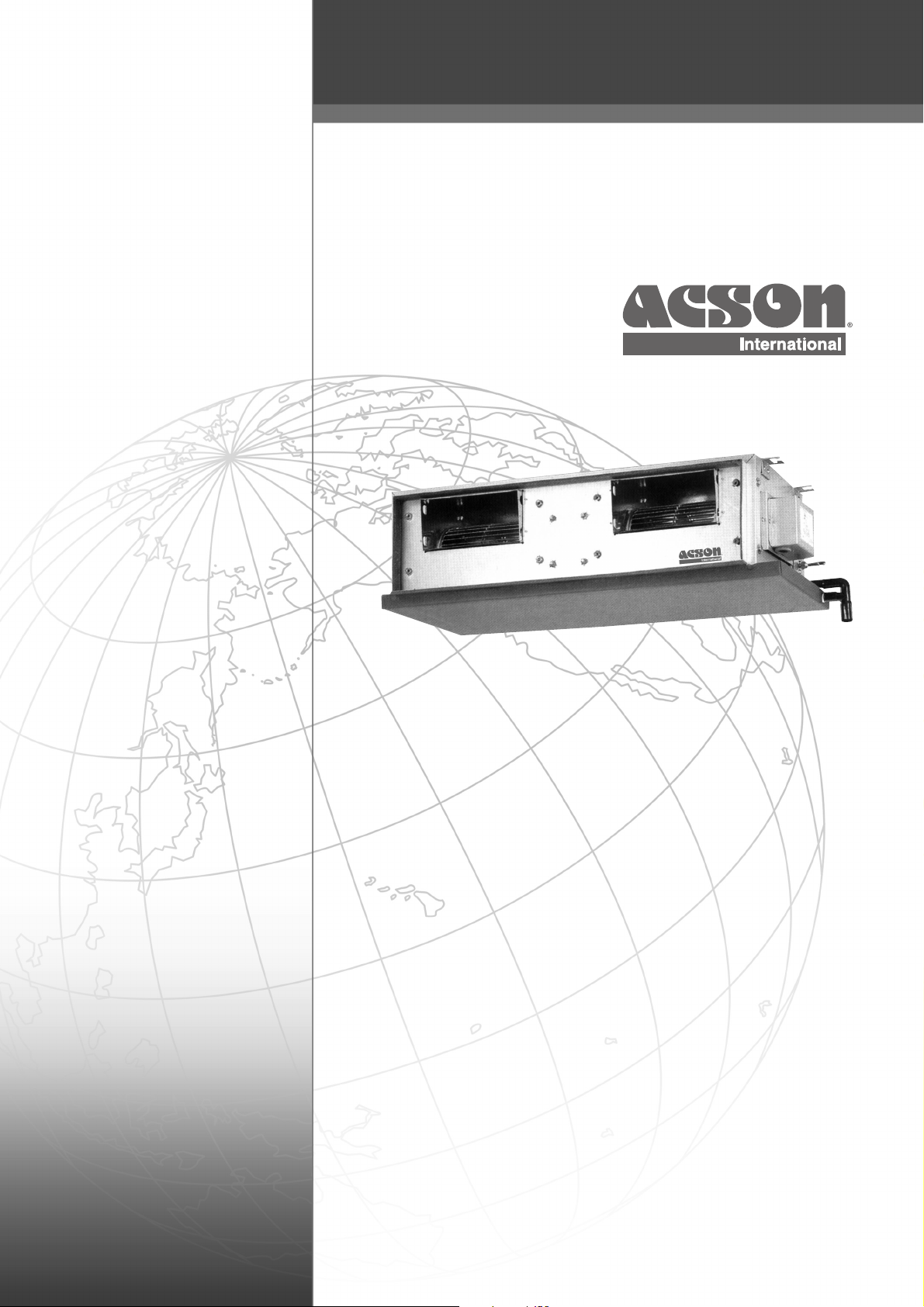
Indoor Unit (CC series)
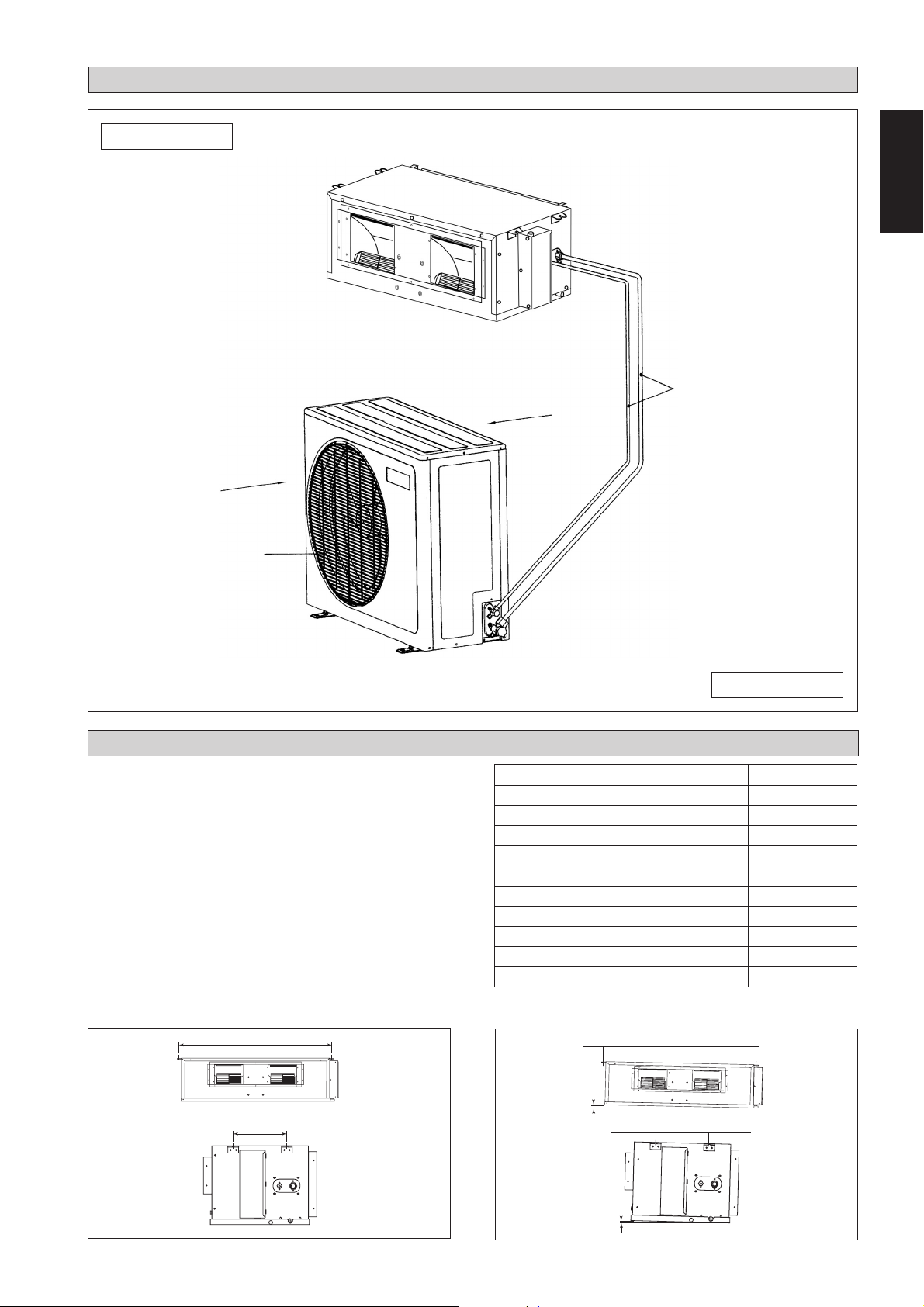
OUTLINE AND DIMENSIONS
I
J
K
L
H
A
E
MN
B
C
D
O
F
G
All dimensions are in mm/(in)
MODEL A B C D E F G H I J K L M N O
CC 10 C/CR
CC 15 C/CR
CC 20 C/CR
CC 25 C/CR
31 741 702 662 10 765 72 261 411 351 225 211 232 212,8 114
(1,2) (29,2) (27,6) (26,1) (0,4) (30,1) (2,8) (10,3) (16,2) (13,8) (8,9) (8,3) (9,1) (8,4) (4,5)
31 881 842 802 10 905 72 261 411 351 225 211 232 212,8 114
(1,2) (34,7) (33,1) (31,6) (0,4) (35,6) (2,8) (10,3) (16,2) (13,8) (8,9) (8,3) (9,1) (8,4) (4,5)
31 1041 1002 962 10 1065 72 261 411 351 225 211 232 212,8 114
(1,2) (41,0) (39,4) (37,9) (0,4) (41,9) (2,8) (10,3) (16,2) (13,8) (8,9) (8,3) (9,1) (8,4) (4,5)
31 1176 1137 1097 10 1200 72 261 411 351 225 211 232 212,8 114
(1,2) (46,3) (44,8) (43,2) (0,4) (47,2) (2,8) (10,3) (16,2) (13,8) (8,9) (8,3) (9,1) (8,4) (4,5)
Indoor Unit (CC series)
61,0 (2,40)
24,5 (0,96)
E
K K
L
AA
40,0
B
C
D
MN
40,0
(1,57)
61,0 (2,40)
E
24,5 (0,96)
15,0
(0,59)
15,0 (0,59)
474,0 (18,66)
142,0 (5,59) 143,0 (5,63)
39,0 (1,54)
40,0 (1,57)
49,0 (1,93)
40,0
(1,57)
I
F
156,0
(6,14)
All dimensions are in mm/(in)
G
H
40,0 (1,57)
90,5
(3,56)
100,0
(3,94)
41,0 (1,61)
26,0 (1,12)
J
187,5 (7,38)
MODEL A B C D E F G H I J K L M N
CC 28C/CR
CC 30C/CR
CC 38C/CR
CC 40C/CR
CC 50C/CR
CC 60C/CR
371,7 1007 959 920 410,0 295 600 339 121 213 64,0 100,0 239 214,0
(14,6) (39,6) (37,8) (36,2) (16,1) (11,6) (23,6) (13,3) (4,8) (8,4) (2,5) (3,9) (9,4) (8,4)
359 999 956 917 408,5 378 541 256 173 306 70,5 160,5 248 220,0
(14,1) (39,3) (37,6) (36,1) (16,1) (14,9) (21,3) (10,1) (6,8) (12,0) (2,8) (6,3) (9,8) (8,7)
371,2 1312 1264 1225 562,5 315 638 401 183 233 217,0 169,2 251 237,8
(14,6) (51,7) (49,8) (48,2) (22,1) (12,4) (25,1) (15,8) (7,2) (9,2) (8,5) (6,7) (9,9) (9,4)
359 1115 1072 1033 466,5 378 541 256 173 306 128,5 160,5 248 220,0
(14,1) (43,9) (42,2) (40,7) (18,4) (14,9) (21,3) (10,1) (6,8) (12,0) (5,1) (6,3) (9,8) (8,7)
359 1369 1326 1287 593,5 378 541 256 173 306 255,5 160,5 248 220,0
(14,1) (53,9) (52,2) (50,7) (23,4) (14,9) (21,3) (10,1) (6,8) (12,0) (10,1) (6,3) (9,8) (8,7)
359 1569 1526 1487 693,5 378 541 256 173 306 355,5 160,5 248 220,0
(14,1) (53,9) (60,1) (58,5) (27,3) (14,9) (21,3) (10,1) (6,8) (12,0) (14,0) (6,3) (9,8) (8,7)
i
Page 4
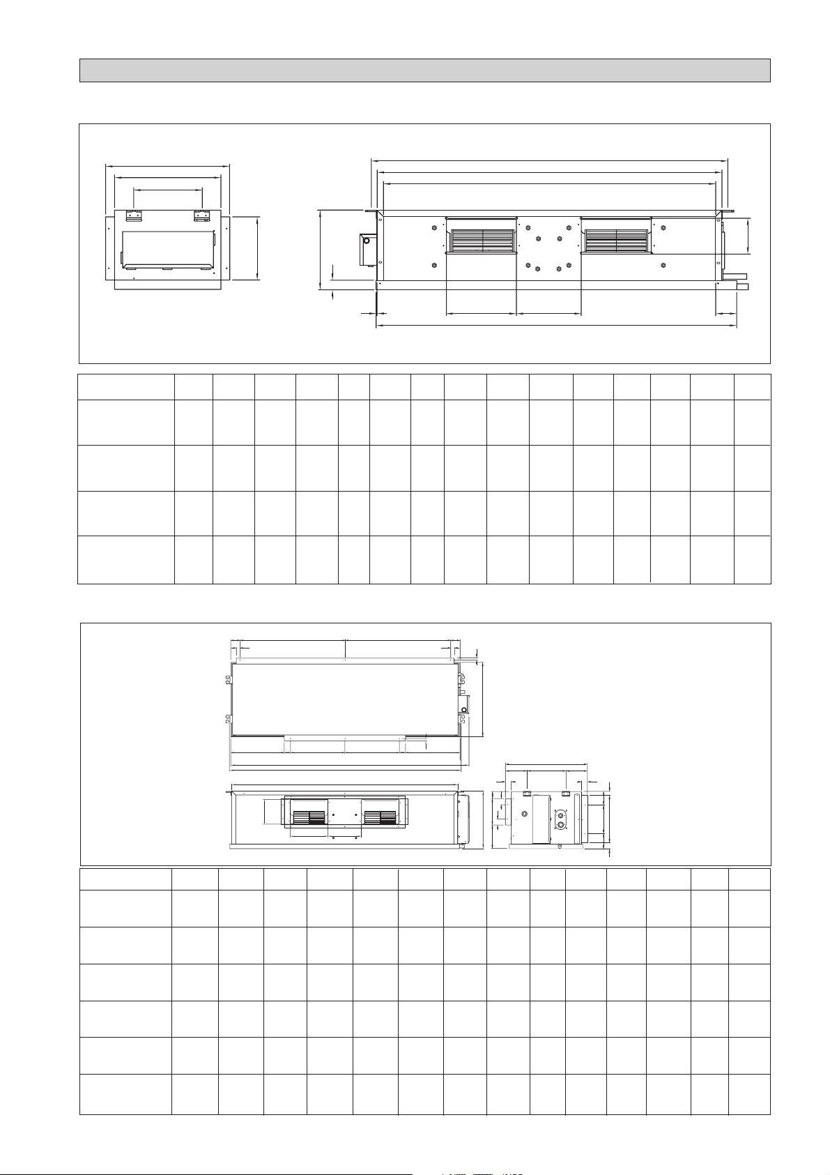
Outdoor Unit (SL-B Series)
A
15 (0,6)
39 (1,5)
R
N
M
P
15 (0,6)
39 (1,5)
5 (0,2)
C
E
20 (0,8)
Q
840 (33,1)
D
P
2.5 (0,1)
F
20 (0,8)
5 (0,2)
B
All dimensions are in mm/(in)
C
H
160 (6,3)
G
141 (5,6)
J
K
(2,6)
65
L
20 (0,8)
Dimension A B C D E F G H J K L M N P Q R
07B / 07BR
10B / 10BR
15B / 15BR
740 494 270 266 233 474 47 55 65 166 92 348 318 129 482 68,5
(29,1) (19,4) (10,6) (10,5) (9,2) (18,7) (1,9) (2,2) (2,6) (6,5) (3,6) (13,7) (12,5) (5,1) (19,0) (2,7)
20B / 20BR
25B / 25BR
30B / 30BR
840 646 330 297 309 626 41 85 75 177 106 408 378 124 592 78,5
(33,1) (25,4) (13,0) (11,7) (12,2) (24,6) (1,6) (3,3) (3,0) (7,0) (4,2) (16,1) (14,9) (4,9) (23,3) (3,1)
Outdoor Unit (SL / 5SL-C Series)
L
O
3
(0,1)
B
19
(0,7)
KL
A
D
(1,2)
All dimensions are in mm/(in)
N
M
CN
30
C
H
G
F
E
65
(2,6)
80
(3,1)
IJ
Dimension A B C D E F G H I J K L M N O
10 / 15 C /CR
700 521 250 485 175 36 95 93 86 68 441 130 111 15 18
(27,5) (20,5) (9,8) (19,1) (6,8) (1,4) (3,7) (3,6) (3,3) (2,6) (17,3) (5,1) (4,3) (0,5) (0,7)
ii
Page 5
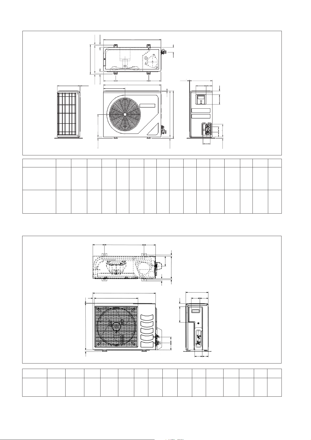
Outdoor Unit (SLC series)
A
P
L
K
M
D
F
B
E
N
C
G
H
J
All dimensions are in mm/(in)
SL A B C D E F G H J K L M N P
30C /40C /50C /60C
(40,6) (33,5) (15,7) (15,4) (16,3) (32,6) (2,8) (7,7) (3,6) (19,2) (17,6) (5,6) (29,4) (3,2)
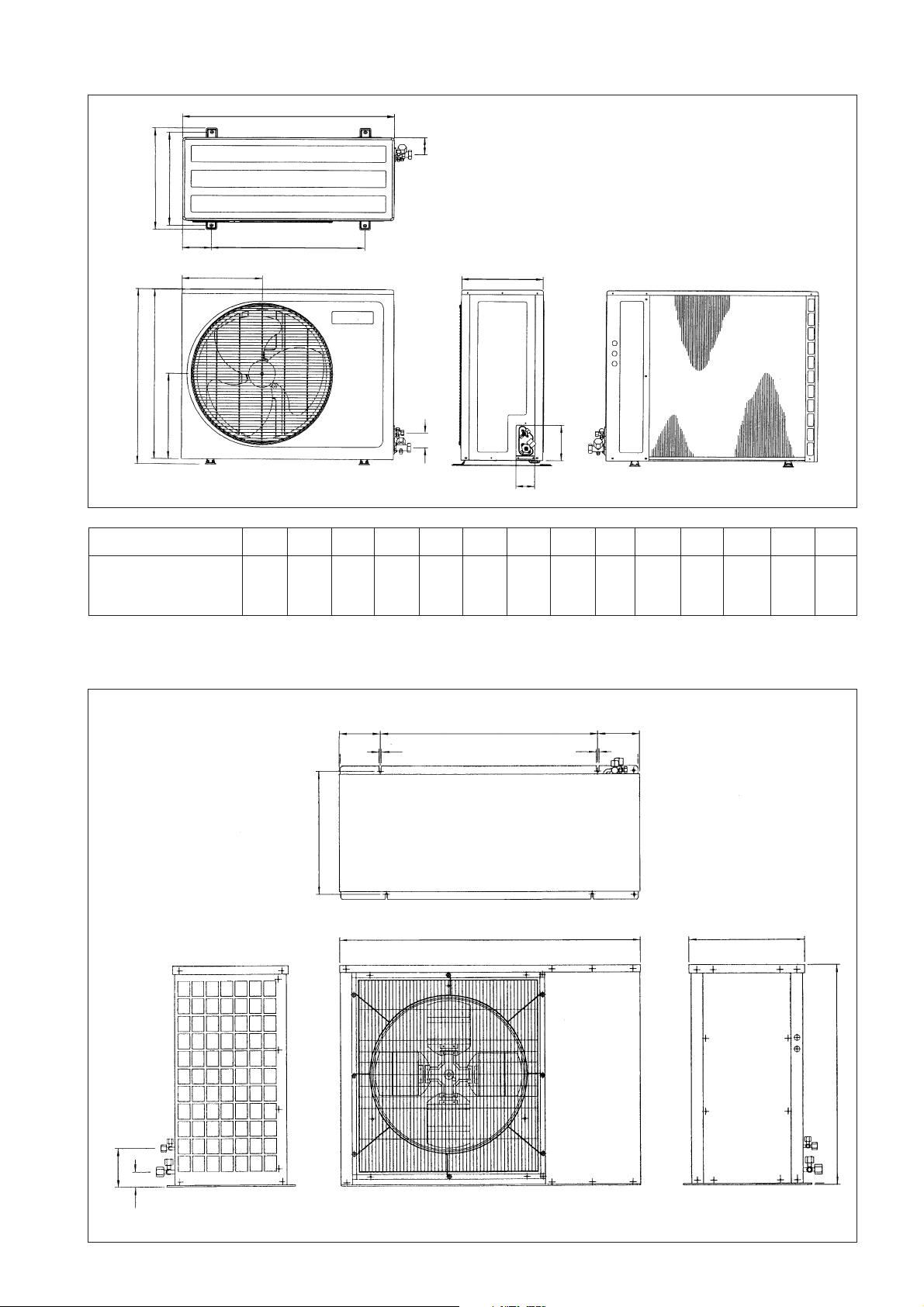
Outdoor Unit (MSS 60C)
1030 850 400 390 414 827 72 196 91 488 448 141,5 746,5 82
180,0 (7,09)
524,0 (20,63)
11,0 (0,43)
940,0 (37,00)
180,0 (7,09)
11,0 (0,43)
500,0 (19,69)1300,0 (51,18)
165,0 (6,50)
65,0
(2,56)
946,0 (37,24)
All dimensions are in mm/(in)
iii
Page 6
! Caution
E
.
P
.
à
la r
é
d
é
t
é
lectroniques (r
ééê
é
s
é
parém
e
é
é
tre ces centres. Ceci
é
.
.
à
à
locali. Questa disposizione
è
i
dell
U.E.
é
ó
n
e
fico
i
ó
i
ó
n
.
G
tes
getrennt vom Hausm
ü
ö
r
M
ü
ö
r
n
ndiges Abfall-Amt. Dieser
Hinweis gilt nur f
nder der Europ
.
о
у
и
в
и
а
о
!
Avertissement
Sharp edges and coil surfaces are potential locations which may cause injury
hazards. Avoid from being in contact with these places.
Les bords coupants et les surfaces du refroidisseur tubulaire présentent
un risque de blessure. Mieux vaut éviter le contact avec ces endroits.
! Vorsicht
Kontakt mit diesen Stellen ist zu vermeiden.
Per preservarsi da eventuali ferite, evitare di toccare gli spigoli affilati e la superficie
Scharfe Kanten und Wärmetauscherflächen stellen eine Gefahrenquelle dar. Jeglicher
! Cautela
dei serpentini.
Los Bordes afilados y la superficie del serpentín pueden producir lesiones. Evite
! Cuidado
! Осторожно
tocarlos.
Острые края и поверхности змеевиков являются потенциальными
местами нанесения травм. Остерегайтесь контакта с этими местами.
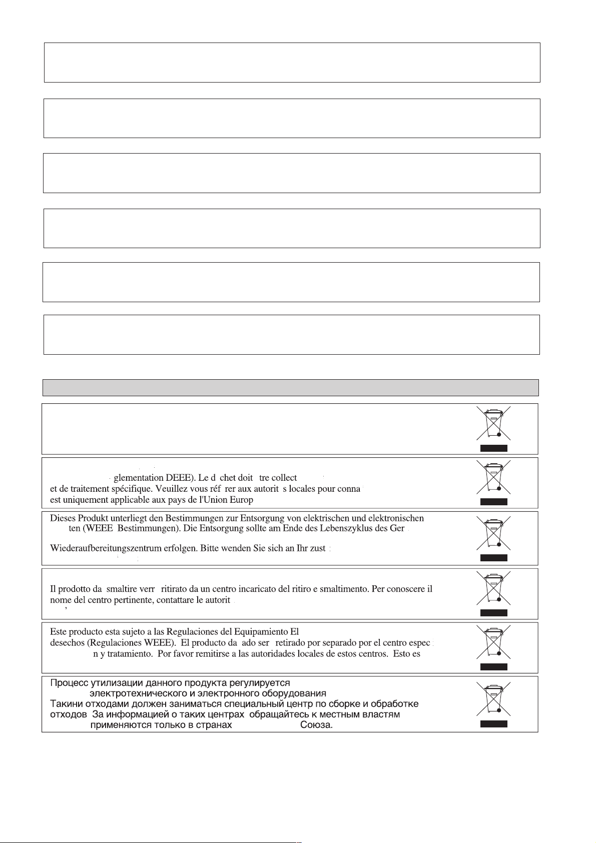
NOTICE
This product is subjected to Waste of Electrical and Electronic Equipment Regulations (WEE
Regulations). The waste product shall be separately collected by specific collection and treatment centre
lease refer to local authorithy for these centres. This is only applicable to European Union countries
Ce produit est soumis
er
Questo prodottoè soggetto alle disposizioni RAEE (Rifiuti di apparecchiature elettriche ed elettroniche)
de colecc
solamente aplicable a los pases de la Un
отходо
правил
glementation concernant les
ll bei Ihrer
tlichen
ischen Union
chets deséquipementsélectriques e
enne
lldeponie bzw. Ihrem
Europea
Европейског
ctrico y Electr
правиламип
ent par un centre de collect
tliche
(WEEE Regulations).
valida solamente i paes
ico en materia d
тилизаци
т
iv
Page 7

INSTALLATION MANUAL
This manual provides the procedures of installation to ensure a safe and good standard of operation for the air
conditioner unit.
Special adjustment may be necessary to suit local requirements.
Before using your air conditioner, please read this instruction manual carefully and keep it for future reference.
CEILING CONCEALED SPLIT TYPE AIR CONDITIONER
MODEL
English
COOLING UNIT
CC10C / ACC10C
SL10B / ALC10B
SL10C / ALC10C
4SL10B / A4LC10B
5SL10C / A5LC10C
CC15C / ACC15C
SL15B / ALC15B
SL15C / ALC15C
4SL15B / A4LC15B
5SL15C / A5LC15C
CC20C / ACC20C
SL20B / ALC20B
4SL20B / A4LC20B
5SL20B / A5LC20B
CC25C / ACC25C
SL25B / ALC25B
4SL25B / A4LC25B
5SL25B / A5LC25B
CC28C / ACC28C
SL30B / ALC30B
SL30C / ALC30C
4SL30C / A4LC30C
5SL30C / A5LC30C
CC30C / ACC30C
SL30B / ALC30B
SL30C / ALC30C
4SL30C / A4LC30C
5SL30C / A5LC30C
CC38C / ACC38C
SL40C / ALC40C
4SL40C / A4LC40C
5SL40C / A5LC40C
CC40C / ACC40C
SL40C / ALC40C
4SL40C / A4LC40C
5SL40C / A5LC40C
CC50C / ACC50C
SL50C / ALC50C
4SL50C / A4LC50C
5SL50C / A5LC50C
CC60C / ACC60C
SL60C / ALC60C
4SL60C / A4LC60C
5SL60C / A5LC60C
MSS60C / AMC60C
HEAT PUMP
CC10CR / ACC10CR
SL10BR / ALC10BR
SL10CR / ALC10CR
4SL10BR / A4LC10BR
5SL10CR / A5LC10CR
CC15CR / ACC15CR
SL15BR / ALC15BR
SL15CR / ALC15CR
4SL15BR / A4LC15BR
5SL15CR / A5LC15CR
CC20CR / ACC20CR
SL20BR / ALC20BR
4SL20BR / A4LC20BR
5SL20BR / A5LC20BR
CC25CR / ACC25CR
SL25BR / ALC25BR
4SL25BR / A4LC25BR
5SL25BR / A5LC25BR
CC28CR / ACC28CR
SL30BR / ALC30BR
SL30CR / ALC30CR
4SL30CR / A4LC30CR
5SL30CR / A5LC30CR
CC30CR / ACC30CR
SL30BR / ALC30BR
SL30CR / ALC30CR
4SL30CR / A4LC30CR
5SL30CR / A5LC30CR
CC38CR / ACC38CR
SL40CR / ALC40CR
4SL40CR / A4LC40CR
5SL40CR / A5LC40CR
CC40CR / ACC40CR
SL40CR / ALC40CR
4SL40CR / A4LC40CR
5SL40CR / A5LC40CR
CC50CR / ACC50CR
SL50CR / ALC50CR
4SL50CR / A4LC50CR
5SL50CR / A5LC50CR
CC60CR / ACC60CR
SL60CR / ALC60CR
4SL60CR / A4LC60CR
5SL60CR / A5LC60CR
MSS60CR / AMC60CR
Part No.: A08019025456
IM-CCC-0501(3)-Acson
1-1
Page 8

CONTENTS
- Outline And Dimensions page i – iv
- Safety Precautions page 2
- Installation Diagram page 3
- Installation Of The Indoor Unit page 3
- Installation Of The Outdoor Unit page 4
- Refrigerant Piping page 4
- Electrical Connection page 5
- Special Precautions When Dealing With R410A Unit page 9
- Special Precautions When Dealing With R407C Unit page 9
- Purging The Refrigerant Piping page 9
- Additional Charge page 10
- Special Precautions When Charging Unit With Copeland Scroll Compressors page 11
- Overall Checking page 12
- Standard Operating Condition page 12
- Auto Random Re-Start Function page 13
- Service And Maintenance page 13
- Troubleshooting page 14
SAFETY PRECAUTIONS
Before installing the air conditioner unit, please read the following safety precautions carefully.
! Warning
• Installation and maintenance should be performed by qualified persons who are familiar with local code and
regulation, and experienced with this type of appliance.
• All field wiring must be installed in accordance with the national wiring regulation.
• Ensure that the rated voltage of the unit corresponds to that of the name plate before commencing wiring work
according to the wiring diagram.
• The unit must be GROUNDED to prevent possible hazard due to insulation failure.
• All electrical wiring must not touch the refrigerant piping, compressor and any moving parts of the fan motors.
• Confirm that the unit has been switched OFF before installing or servicing the unit.
IMPORTANT
DO NOT INSTALL OR USE THE AIR CONDITIONER UNIT IN A LAUNDRY ROOM.
! Caution
Please take note on the following important points when installing.
• Do not install the unit where leakage of flammable gas may occur.
If gas leaks and accumulates at the surrounding of the unit, it may cause fire ignition.
• Ensure that the drainage piping is connected properly.
If the drainage piping is not connected properly, it may cause water leakage which will dampen the
furniture.
• Do not overcharge the unit.
This unit is factory pre-charged. Overcharge will cause over-current or damage to the compressor.
• Ensure that the unit panel is covered back after service or installation.
Unsecured panel will cause unit to operate noisily.
1-2
Page 9
Indoor unit
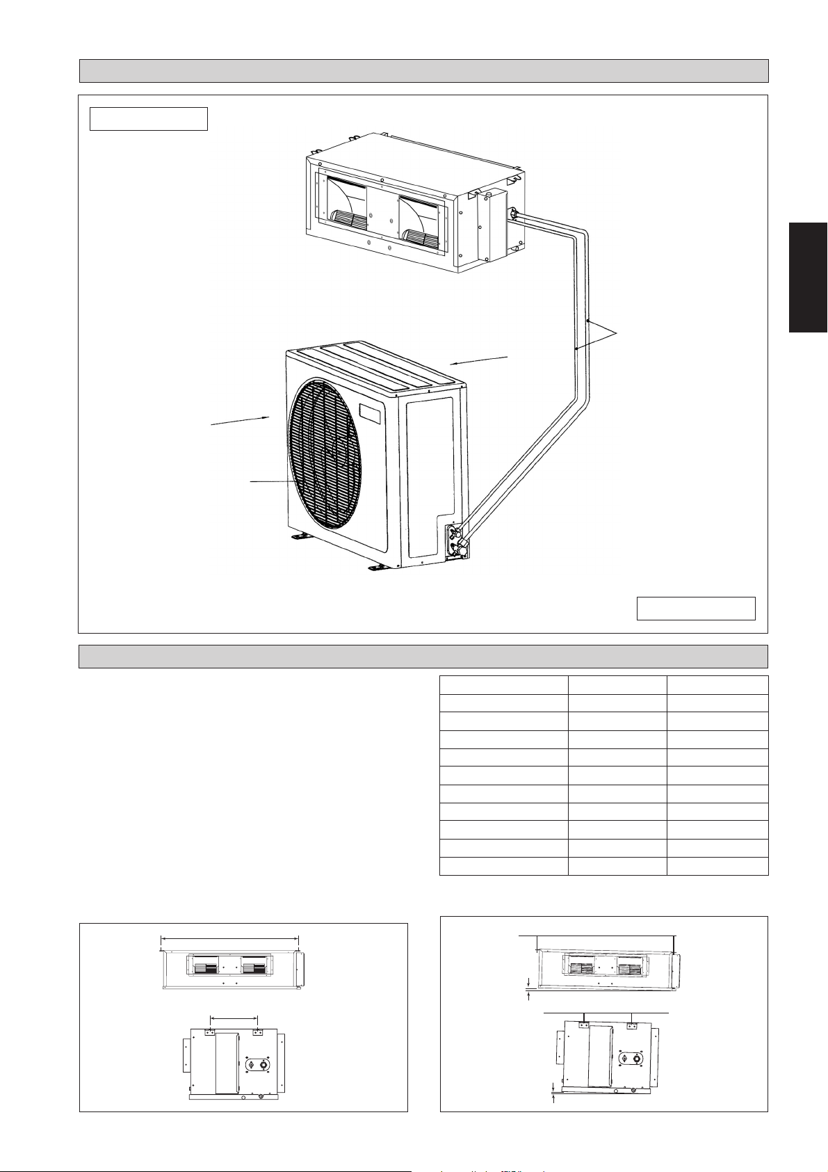
INSTALLATION DIAGRAM
English
Air Intake
Air Discharge Nozzle
INSTALLATION OF THE INDOOR UNIT
The indoor unit must be installed such that there is no short
circuit of the cool discharge. Respect the installation
clearance. Do not put the indoor unit where there is direct
sunlight on unit. The location is suitable for piping and
drainage and it must be have a large distance between a
door and unit.
Ceiling Concealed Mounting
– Use the hanger supplied with the unit.
– Make sure that the wall is sufficiently strong to withstand
the weight.
Center distance of axle (see drawing below)
A
Air Intake
Refrigerant Piping
Outdoor unit
CC A mm (inch) L mm (inch)
10 C/CR 741 (29.2) 225 (8.9)
15 C/CR 881 (34.7) 225 (8.9)
20 C/CR 1041 (41.0) 225 (8.9)
25 C/CR 1176 (46.3) 225 (8.9)
28 C/CR 959 (37.8) 339 (13.3)
30 C/CR 956 (37.6) 266 (10.5)
38 C/CR 1264 (49.8) 401 (15.8)
40 C/CR 1076 (42.4) 266 (10.5)
50 C/CR 1326 (52.2) 266 (10.5)
60 C/CR 1526 (60.1) 266 (10.5)
Provide clearance for servicing ease and optimal air flow as
shown in the diagram.
L
10 mm (32.8)
10 mm (32.8)
1-3
Page 10

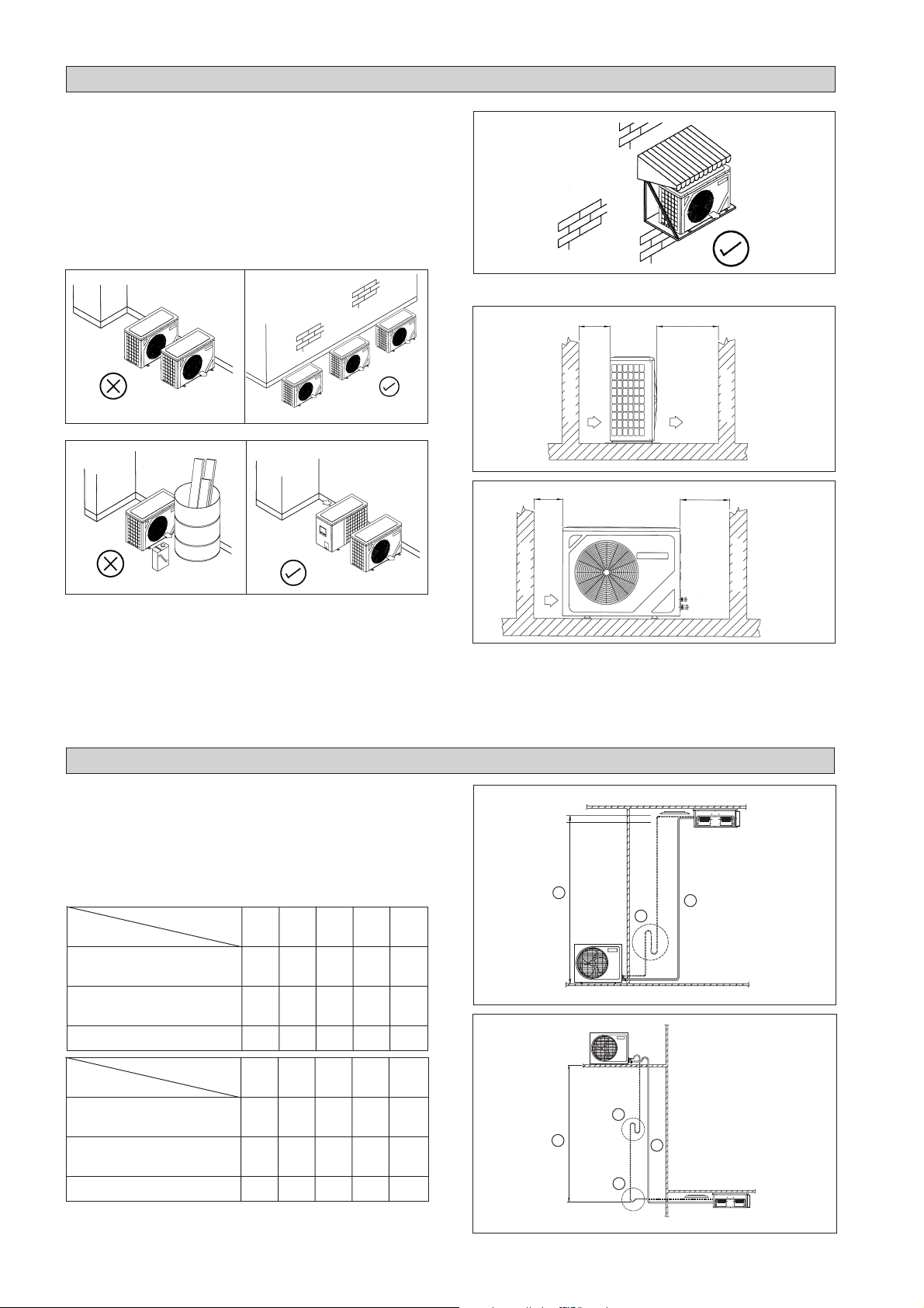
INSTALLATION OF THE OUTDOOR UNIT
The outdoor unit must be installed such that there is no short
circuit of the discharge air or obstruction to smooth air flow.
Respect the installation clearance. Select the coolest possible
place where intake air should not be higher than the outside
temperature (maximum 45°C).
Ensure that there are no obstruction of air flow into or out
of the unit. Remove obstacles which block air intake or
discharge.
Outdoor Unit SL Series Clearance (in mm)
The location must be well-ventilated, so that the unit can
draw in and distribute plenty of air thus lowering the
temperature.
A place capable of bearing the weight of the outdoor unit as
well as isolating noise and vibration.
A place protected from the direct sunlight. Use an
awning for protection if necessary.
The installation location must not be susceptible to highly
concentrated dust, oil, salt or sulfide gas.
REFRIGERANT PIPING
300
Obstacle
Return Air
300
Obstacle
Return Air
1000
Discharge
Air
500
Service
Access
Obstacle
Obstacle
Note:- If the obstacle is higher than 2 m or if there is any
obstruction at the upper part of the unit allow more
space than indicated in the table above.
Maximum Pipe Length And Maximum Number Of
Bends
When the pipe length becomes too long, both the capacity
and reliability drop. As the number of bends increases,
system piping resistance to the refrigerant flow increases,
thus lowering the cooling capacity. As a result, compressor
reliability will be affected. Always choose the shortest path
and follow the recommendation as tabulated below:
Model
Data
Maximum Length, A m (ft)
Maximum Elevation, B m (ft)
Maximum No. of Bends, C 10 10 10 10 10
Model
Data
Maximum Length, A m (ft)
Maximum Elevation, B m (ft)
Maximum No. of Bends, C 10 10 10 10 8
Remark : For CC60C cooling unit, recommended to add
6 kg external accumulator.
10 15 20 25 28
12 12 15 15 35
(39.4) (39.4) (49.2) (49.2) (114.8)
558810
(16.4) (16.4) (26.2) (26.2) (32.8)
30 38 40 50 60
35 35 35 35 35
(114.8)(114.8)(114.8)(114.8) (114.8)
10 10 10 10 10
(32.8) (32.8) (32.8) (32.8) (32.8)
1-4
A
C
C
A
C
B
B
Page 11
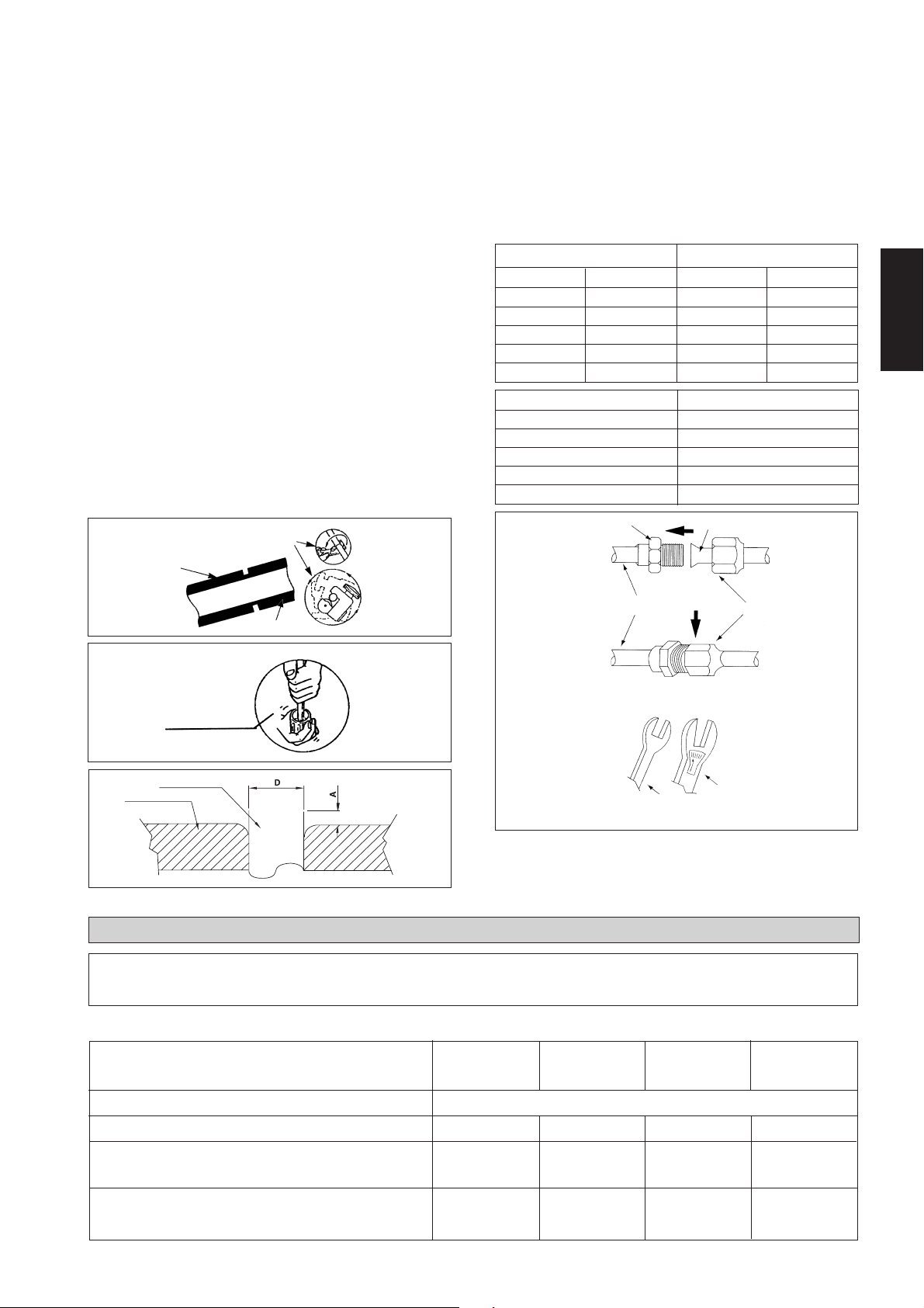
Piping Works And Flaring Technique
Do not use contaminated or damaged copper tubing. If any
piping, evaporator or condenser had been exposed or had
been opened for 15 seconds or more, vacuum the system.
Generally, do not remove plastic, rubber plugs and brass
nuts from the valves, fittings, tubings and coils until it is
ready for connection.
If any brazing work is required, ensure that the nitrogen gas
is passed through piping and joints while the brazing work
is being done. This will eliminate soot formation on the
inside walls of the copper tubings.
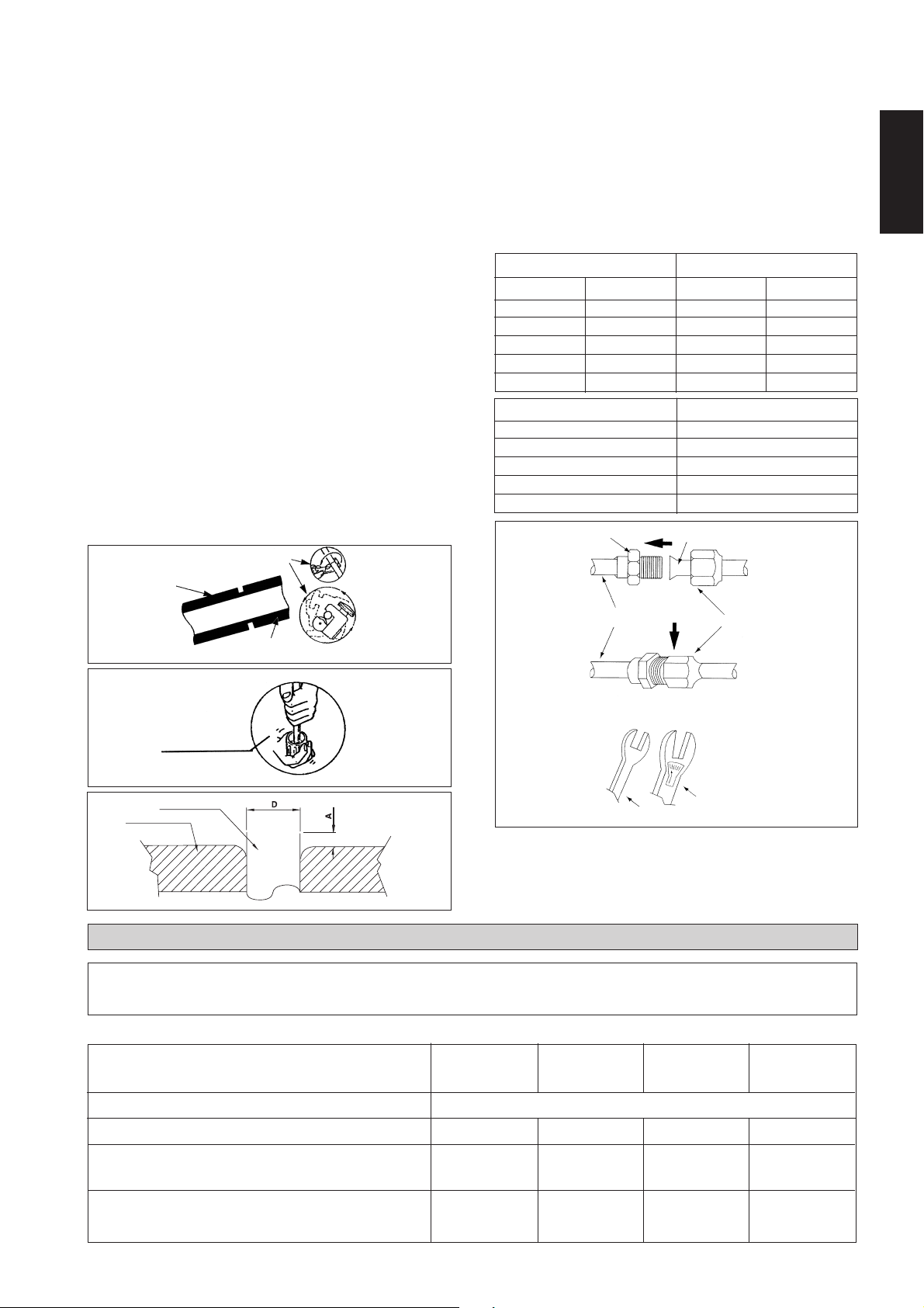
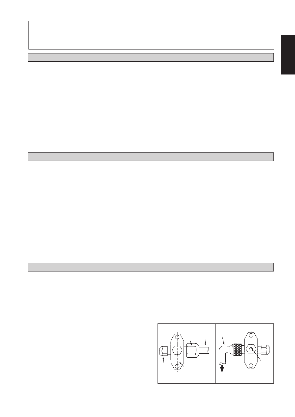
Cut the pipe stage by stage, advancing the blade of pipe
cutter slowly. Extra force and deep cut will cause more
distortion of pipe and therefore extra burr.
Remove burrs from cut edges of pipes with a remover as
shown in Fig. R. This will avoid unevenness on the flare
faces which will cause gas leak. Hold the pipe on top position
and burr remover at lower position to prevent metal chips
from entering the pipe.
Insert the flare nuts mounted on the connection parts of both
indoor and outdoor unit, into the copper pipes.
The exact length of pipe protruding from the face of the
flare die is determined by the flaring tool.
Fix the pipe firmly on the flare die. Match the centers of
both the flare die and the flaring punch, and tighten flaring
punch fully.
Cutting Copper Tube
Piping Connection To The Units
Align the center of the piping and sufficiently tighten the
flare nut with fingers.
Finally, tighten the flare nut with torque wrench
until the wrench clicks.
When tightening the flare nut with the torque wrench,
ensure that the direction for tightening follows the arrow on
the wrench.
The refrigerant pipe connection are insulated by
polyurethane (ARMAFLEX type or similar).
Ø Tube, D A (mm)
Inch mm Imperial Rigid
1/4" 6.35 1.3 0.7
3/8" 9.52 1.6 1.0
1/2" 12.70 1.9 1.3
5/8" 15.88 2.2 1.7
3/4" 19.05 2.5 2.0
Pipe Size, mm (in) Torque (Nm)
6.35 (1/4) 18
9.53 (3/8) 42
12.7 (1/2) 55
15.88 (5/8) 65
19.05 (3/4) 78
Flare Joint
Flared Tube
English
1/4t
Copper Tube
Fig. R
Remove Burr
Swaging Block
Copper Tube
Ensure the color of wires of the outdoor unit and the terminal markings are same to
! Caution
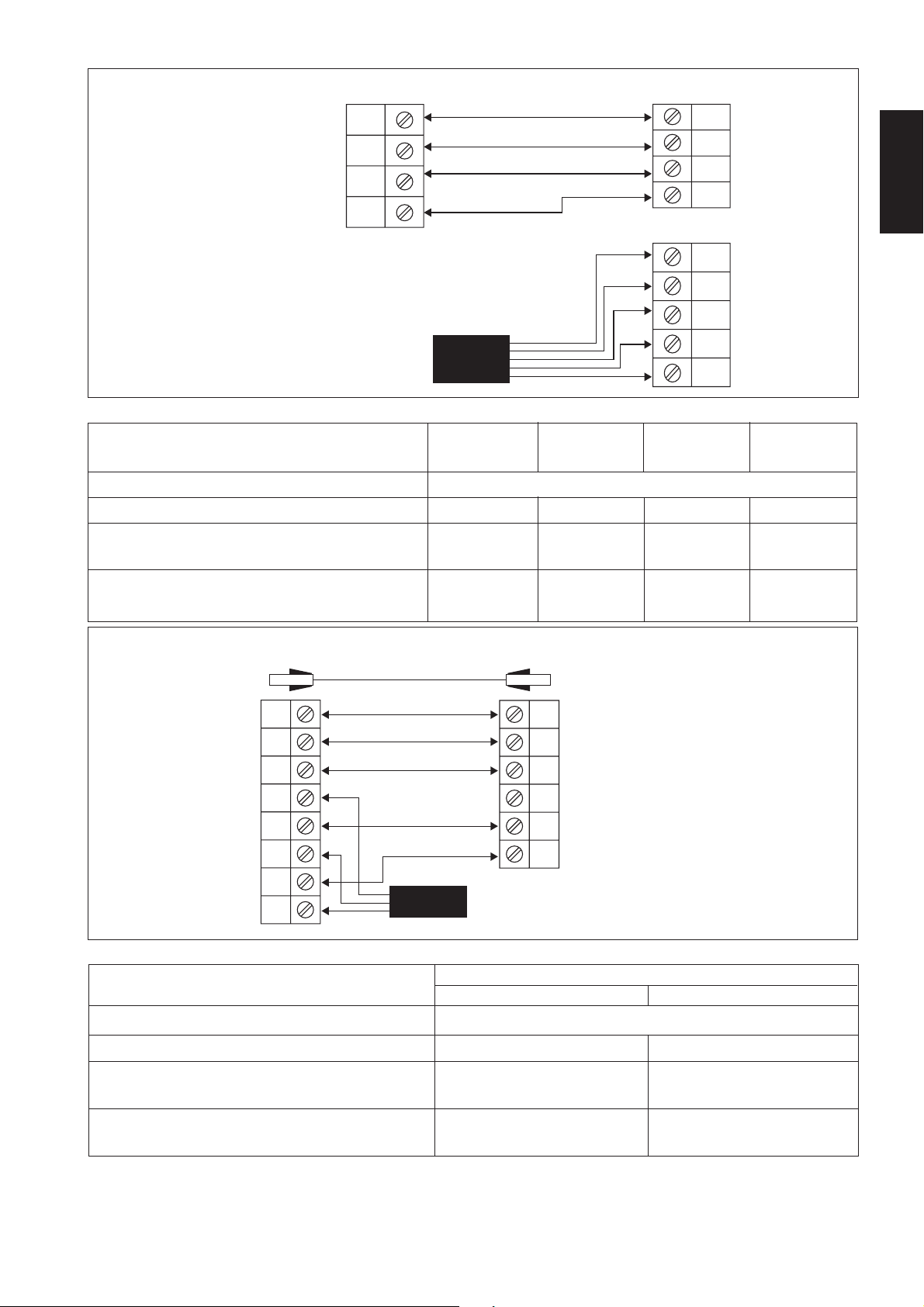
Cooling Only Units, CC 10 / 15 / 20 / 25 C
the indoors respectively.
Indoor Piping
ELECTRICAL CONNECTION
Spanar
Flare Nut
Torque Wrench
Indoor unit CC 10C CC 15C CC 20C CC 25C
Outdoor unit SL 10B SL 15B SL 20B SL 25B
Voltage range**
220V–240V /1Ph /50Hz + ! or 208V–230V /1Ph /60Hz + !
Recommended fuse* A 10 10 16 20
Power supply cable size* mm
2
1.5 1.5 2.5 2.5
Number of conductors 3333
Interconnection cable size* mm
2
1.5 1.5 2.5 2.5
Number of conductors 3333
1-5
Page 12
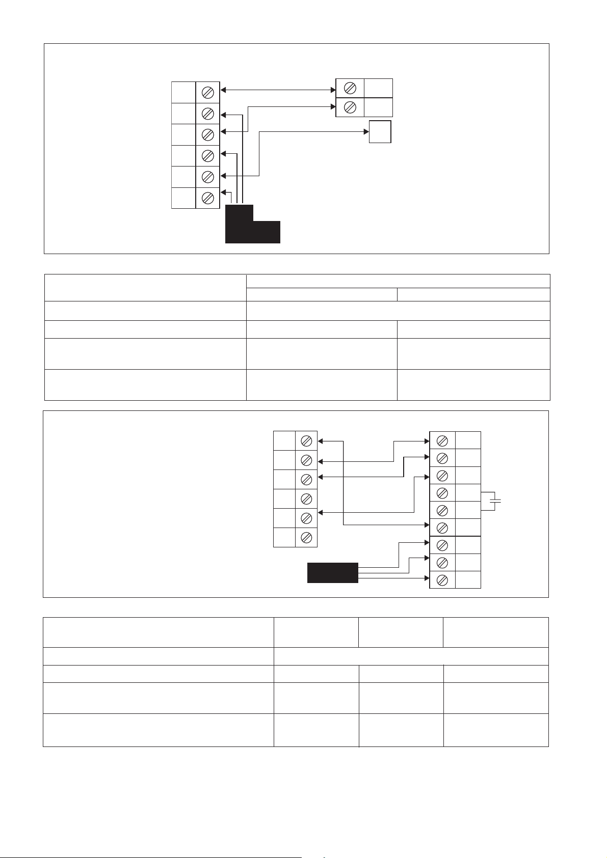
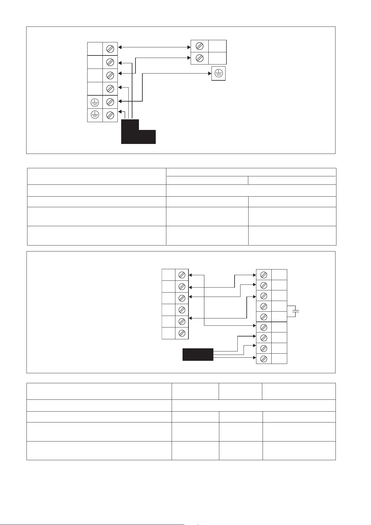
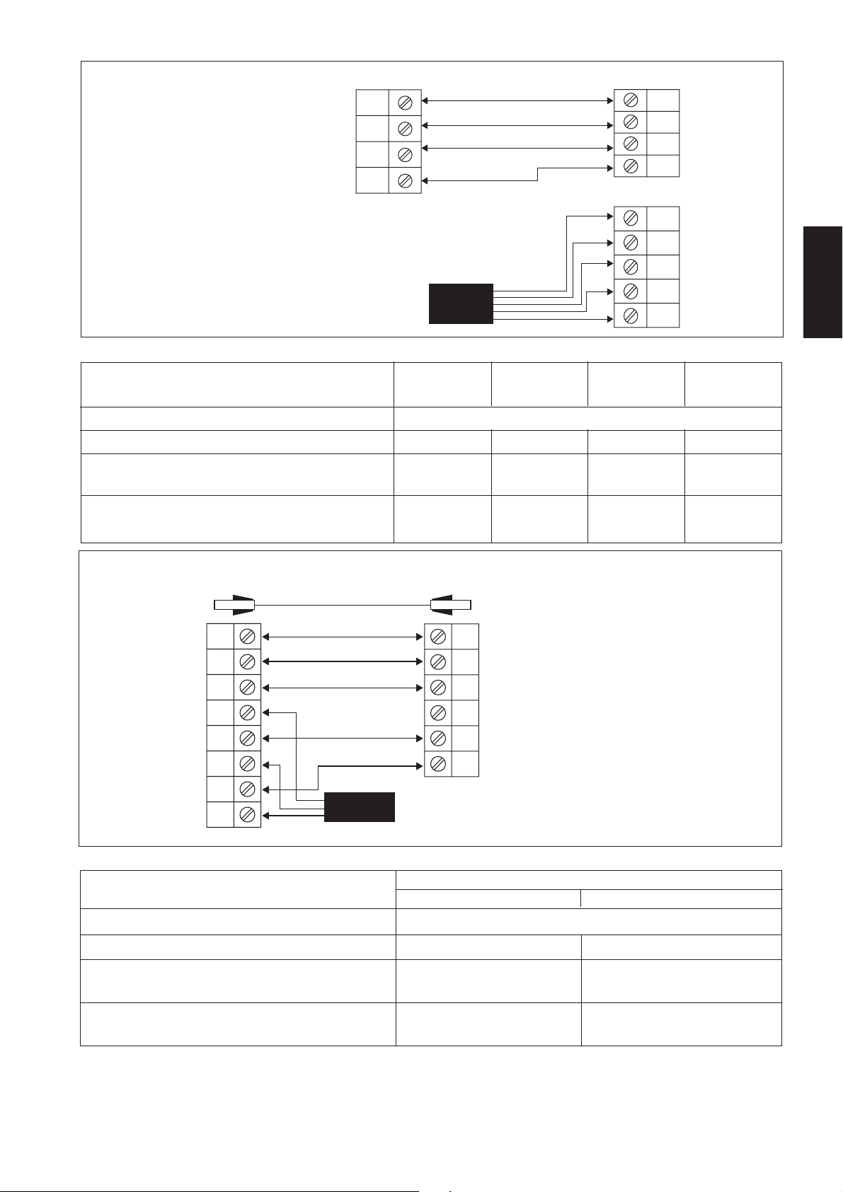
CC 10 / 15 / 20 / 25 C - SL 10 / 15 / 20 / 25 B
CC 28 / 30 C - SL 30 B
COMP
N
!
Terminal Strip
Outdoor unit
Terminal Strip
Indoor unit
COMP
L
N
N
!
2
2
Power Supply
Cable
There must be a double pole switch
!
with a minimum 3 mm contact gap and
fuse / circuit breaker as recommended
in the fixed installation circuits.
4.0 4.0
2.5 2.5
!
Cooling Only Units, CC 28 / 30 C
Indoor unit CC 28 / 30C
Outdoor unit SL 30B SL 30C
Voltage range** 220V–240V / 1Ph / 50Hz + ! or 208V–230V / 1Ph / 60Hz + !
Recommended fuse* A 25 25
Power supply cable size* mm
Number of conductors 33
Interconnection cable size* mm
Number of conductors 34
CC 28 / 30 C - SL 30 C
Terminal Strip
Indoor Unit
COMP
L
N
N
L
N
!
S
Terminal Strip
Outdoor Unit
R
There must be a double pole switch
!
with a minimum 3 mm contact gap and
fuse / circuit breaker as recommended
in the fixed installation circuits.
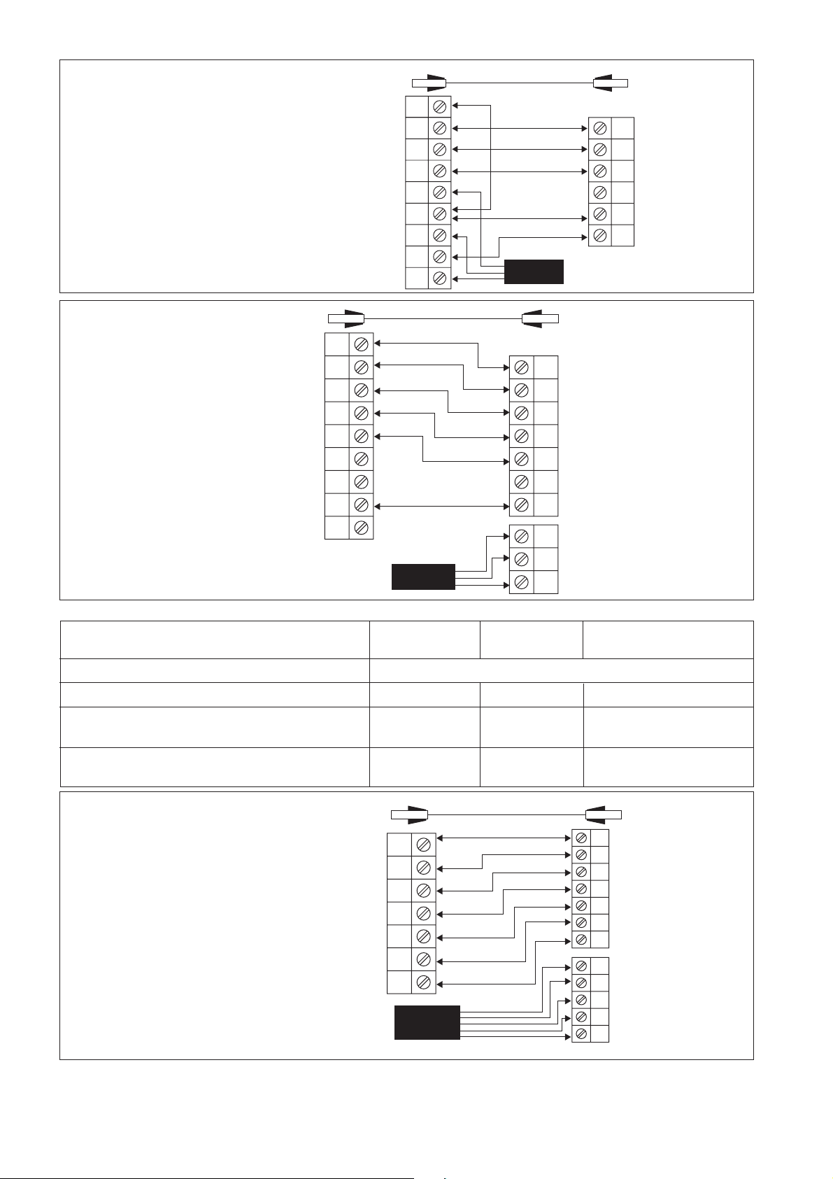
Cooling Only Units, CC 38 / 40 / 50 / 60 C
Indoor unit
Outdoor unit
Voltage range**
!
!
Power Supply
Cable
CC 38 / 40C CC 50C CC 60C
SL 40C SL 50C SL 60C or MSS 60C
380V– 415V /3Ph /50Hz +N + ! or 208V–230V / 3Ph /60Hz + N + !
COMP
L
N
!
Recommended fuse* (50/ 60Hz) A 10/20 16/25 16/25
Power supply cable size* (50/ 60Hz) mm
2
1.5/2.5 2.5/4.0 2.5/4.0
Number of conductors 55 5
Interconnection cable size* (50/ 60Hz) mm
2
1.5/1.5 1.5/1.5 1.5/1.5
Number of conductors 44 4
IMPORTANT: * These values are for information only, they should be checked and selected to comply with the local and/or national
codes and regulations. They are also subjected to the type of installation and size of conductors.
** The appropriate voltage range should be checked with data label on the unit. ETL listed unit is only applicable to
60Hz power supply only.
1-6
Page 13
CC 38 / 40 / 50 / 60 C - SL 40 / 50 / 60 C
COMP
L
N
Terminal Strip
Indoor Unit
COMP
L
N
!
!
There must be a double pole switch
!
with a minimum 3 mm contact gap and
fuse / circuit breaker as recommended
in the fixed installation circuits.
Heat Pump Units, CC 10 / 15 / 20 / 25 CR
Indoor unit CC 10CR CC 15CR CC 20CR CC 25CR
Outdoor unit SL 10BR SL 15BR SL 20BR SL 25BR
Voltage range**
Recommended fuse* A 10 10 16 20
Power supply cable size* mm
Number of conductors 33 3 3
Interconnection cable size* mm
Number of conductors 55 5 5
Power Supply Cable
220V–240V /1Ph /50Hz + ! or 208V–230V /1Ph /60Hz + !
2
2
1.5 1.5 2.5 2.5
1.5 1.5 2.5 2.5
Terminal Strip
Outdoor Unit
R
S
T
N
!
English
CC 10 / 15 / 20 / 25 CR - SL 10 / 15 / 20 / 25 BR
Outdoor Coil Sensor
4WV
OF
COMP
Terminal Strip
Indoor Unit
L
N
N
!
!
Heat Pump Units, CC 28 / 30 CR
Power Supply Cable
4WV
OF
COMP
N
!
Terminal Strip
Outdoor Unit
There must be a double pole switch
!
with a minimum 3 mm contact gap and
fuse / circuit breaker as recommended
in the fixed installation circuits.
Indoor unit CC 28/30 CR
Outdoor unit SL 30BR SL 30CR
Voltage range** 220V–240V /1Ph /50Hz + ! or 208V–230V /1Ph /60Hz + !
Recommended fuse* A 25 25
Power supply cable size* mm
2
4.0 4.0
Number of conductors 33
Interconnection cable size* mm
2
2.5 2.5
Number of conductors 56
IMPORTANT: * These values are for information only, they should be checked and selected to comply with the local and/or national
codes and regulations. They are also subjected to the type of installation and size of conductors.
** The appropriate voltage range should be checked with data label on the unit. ETL listed unit is only applicable to
60Hz power supply only.
1-7
Page 14

CC 28 / 30 CR - SL 30 BR
There must be a double pole switch
!
with a minimum 3 mm contact gap and
fuse / circuit breaker as recommended
in the fixed installation circuits.
Terminal Strip
Indoor Unit
A
4WV
OF
COMP
L
N
N
!
!
Outdoor Coil Sensor
4WV
OF
Terminal Strip
COMP
Outdoor Unit
N
!
Power Supply Cable
CC 28 / 30 CR - SL 30 CR
Outdoor Coil Sensor
A
Terminal Strip
Indoor Unit
There must be a double pole switch
!
with a minimum 3 mm contact gap
and fuse / circuit breaker as
recommended in the fixed installation
circuits.
Heat Pump Units, CC 38 / 40 / 50 / 60 CR
Indoor unit
Outdoor unit
Voltage range**
4WV
OF
COMP
L
N
N
!
!
Power Supply Cable
CC 38 / 40CR CC 50CR CC 60CR
SL 40CR SL 50CR SL 60CR or MSS 60CR
380V– 415V /3Ph /50Hz +N + ! or 208V – 230V /3Ph /60Hz + N + !
A
4WV
OF
COMP
L
N
!
L
N
!
Terminal Strip
Outdoor Unit
Recommended fuse* (50/60Hz) A 10/20 16/25 16/25
Power supply cable size* (50/60Hz) mm
2
1.5/2.5 2.5/4.0 2.5/4.0
Number of conductors 55 5
Interconnection cable size* (50/60Hz) mm
2
1.5/1.5 1.5/1.5 1.5/1.5
Number of conductors 77 7
CC 38 / 40 / 50 / 60 CR - SL 40 / 50 / 60 CR
Terminal Strip
Indoor Unit
There must be a double pole switch
!
with a minimum 3 mm contact gap and
fuse / circuit breaker as recommended
in the fixed installation circuits.
A
4WV
OF
COMP
L
N
!
Power Supply Cable
Outdoor Coil Sensor
A
4WV
OF
COMP
L
N
!
R
S
T
N
!
Terminal Strip
Outdoor Unit
IMPORTANT: * These values are for information only, they should be checked and selected to comply with the local and/or national
codes and regulations. They are also subjected to the type of installation and size of conductors.
** The appropriate voltage range should be checked with data label on the unit. ETL listed unit is only applicable to
60Hz power supply only.
1-8
Page 15
! Caution
Ensure that the colors of wires on the outdoor unit and the terminal markings are the same as the indoor unit
respectively.
SPECIAL PRECAUTIONS WHEN DEALING WITH R410A UNIT
R410A is a new HFC refrigerant which does not damage the
ozone layer. The working pressure of this new refrigerant is
1.6 times higher than conventional refrigerant (R22), thus
proper installation / servicing is essential.
• Never use refrigerant other than R410A in an air condi-
tioner which designed to operate with R410A.
• POE oil is used as lubricant for R410A compressor, which
is different from the mineral oil used for R22 compressor.
During installation or servicing, extra precaution must be
taken not to expose the R410A system too long to moist
air. Residual POE oil in the piping and components can
absorb moisture from the air.
• To prevent mischarging, the diameter of the service port
on the flare valve is different from that of R22.
SPECIAL PRECAUTIONS WHEN DEALING WITH R407C UNIT
• Use tools and materials exclusively for refrigerant R410A.
Tools exclusively for R410A are manifold valve, charging
hose, pressure gauge, gas leak detector, flare tools, torque
wrench, vacuum pump and refrigerant cylinder.
• As an R410A air conditioner incurs higher pressure than
R22 units, it is essential to choose the copper pipes correctly. Never use copper pipes thinner than 0.8mm even
though they are available in the market.
• If the refrigerant gas leakage occurs during installation /
servicing, be sure to ventilate fully. If the refrigerant gas
comes into contact with fire, a poisonous gas may occur.
• When installing or removing an air conditioner, do not
allow air or moisture to remain in the refrigerant cycle.
English
• R407C is a zeotropic refrigerant mixture which has zero
ozone depletion potential and thus conformed to the
Montreal Protocol regulation. It requires Polyol ester oil
(POE) oil for its compressor's lubricant. Its refrigerant
capacity and performance are about the same as the
refrigerant R22.
• POE oil is used as lubricant for R407C compressor, which
is different from the mineral oil used for R22 compressor.
During installation or servicing, extra precaution must be
taken not to expose the R407C system too long to moist
air. Residual POE oil in the piping and components can
absorb moisture from the air.
• Refrigerant R407C is more easily affected by dust of
moisture compared with R22, make sure to temporarily
cover the ends of the tubing prior to installation.
• No additional charge of compressor oil is permitted.
PURGING THE REFRIGERANT PIPING
Purging The Piping And The Indoor Unit
Except the outdoor unit which is pre-charged with
refrigerant, the indoor unit and the refrigerant connection
pipes must be air purged because the air that contain moisture
remaining in the refrigerant cycle may cause malfunction to
the compressor.
• No other refrigerant other than R407C.
• Tools specifically for R407C only (must not be used for
R22 or other refrigerant)
i) Manifold gauge and charging hose
ii) Gas leak detector
iii) Refrigerant cylinder/charging cylinder
iv) Vacuum pump c/w adapter
v) Flare tools
vi) Refrigerant recovery machine
• Filter-dryer must be installed along the liquid line for all
R407C air conditioners. This is to minimise the
contamination of moisture and dirt in the refrigerant
system. Filter-dryer must be of molecular sieve type. For
a heat-pump system, install a two-way flow filter dryer
along the liquid line.
• Close the manifold valve and stop the vacuum pump.
• On the outdoor unit, open the suction and liquid valve
(anti clockwise) with 4 mm key for hexagon sacked screw.
• The air conditioner unit is ready for start.
• If the reading is close to 0, the refrigerant circuit must be
evacuated (by vacuum pump) and charged again.
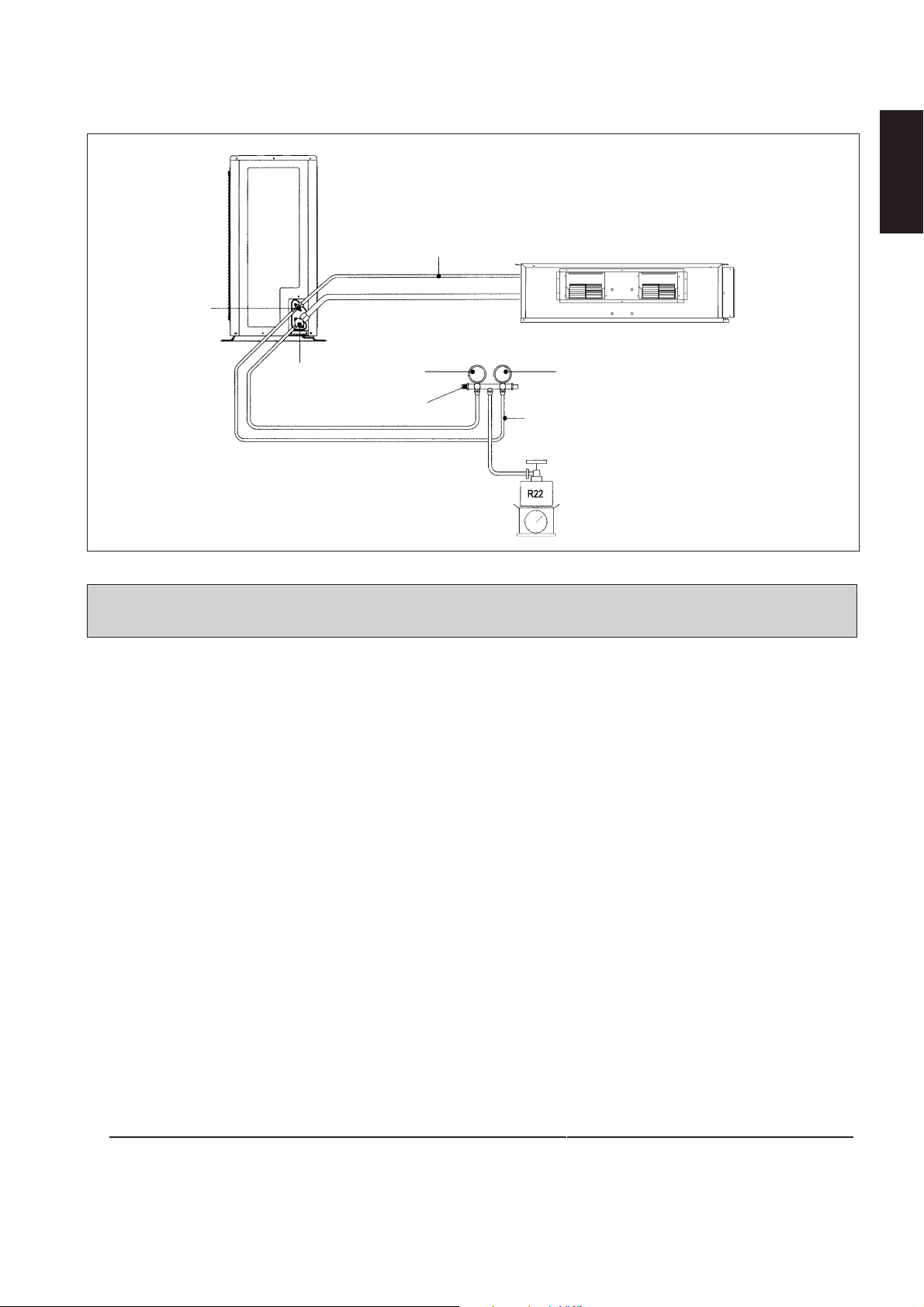
The outdoor unit is equipped by two 3 ways refrigerating
connecting valves. The suction valve is the larger one while
the small one is the liquid valve. Both valves are supplied
with service port valve for connection to a manometer.
• Remove the caps from the valve and the service port.
• Connect the center manifold gauge with the vacuum pump.
• Connect the manifold gauge to the service port of the 3
ways valve.
• Start the vacuum pump. Check the low pressure manifold
gauge until it indicate 0.9 bar. The evacuation time varies
with each vacuum pump capacity but generally in half an
hour.
1-9
Service
Port
Refrigerant
Flare
Piping
Nut
Outdoor Unit
3 way Valve
Flexible Hose
4 mm
Allen
Key
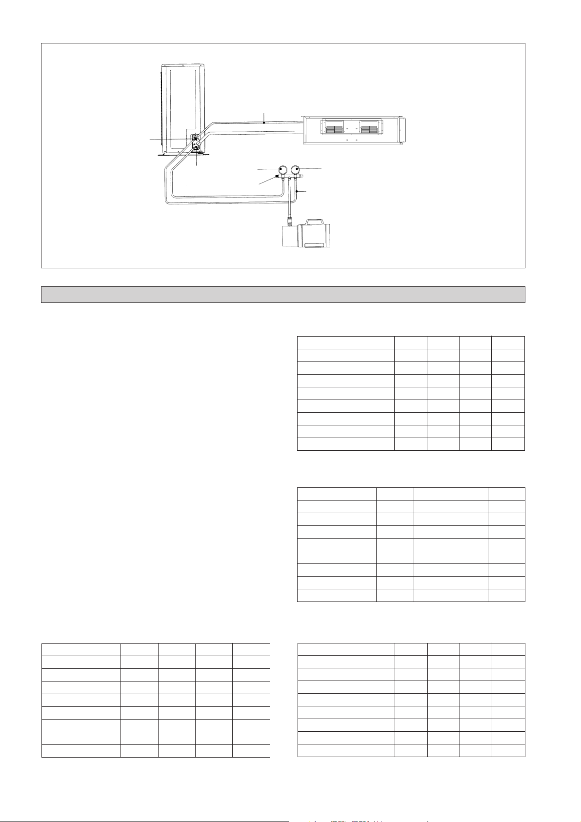
Page 16

Outdoor Unit
Refrigerant Piping
Liquid Valve
Low Side
Pressure Gauge
Gas Valve
Manifold
ADDITIONAL CHARGE
The refrigerant is pre-charged in the outdoor unit. If the
piping length is less than 5 m, additional charge after vacuuming is not necessary. When the piping length is more than
5 m, use the table below.
Additional Charge Operation
This operation must be done by using gas cylinder and a
precise weighing machine obligatorily. The additional charge
is top up into the outdoor unit by suction valve via service
port.
• Remove the service valve plug.
• Connect the low pressure manifold to the suction service
port, center manifold to the cylinder tank and close the
high pressure manifold (see figure below).
Purge all the flexible hose with refrigerant gas.
• Start the air conditioner unit.
• Open the gas cylinder and low pressure manifold valve.
• When the required refrigerant quantity is pumped in the
unit, close the low pressure manifold and the gas cylinder
valve.
• Disconnect the manometer and the gas cylinder. Place back
the service port cap.
Additional Charge in Gram (Cooling Only Unit) (R410A)
Model 7 m 10 m 15 m 20 m
CC 10C 27 67 – –
CC 15C 27 67 – –
CC 20C 27 67 135 –
CC 25C 68 171 342 –
CC 28C / CC 30C 90 225 450 675
CC 38C / CC 40C 90 225 450 675
CC 50C 90 225 450 675
CC 60C 90 225 450 675
Indoor Unit
High Pressure Gauge
Flexible Hose
Vacuum Pump
Additional Charge in Gram (Heat Pump Unit) (R410A)
Model 7 m 10 m 15 m 20 m
CC 10CR 36 90 – –
CC 15CR 36 90 – –
CC 20CR 45 112 225 –
CC 25CR 90 225 450 –
CC 28CR / CC 30CR 90 225 450 675
CC 38CR / CC 40CR 90 225 450 675
CC 50CR 90 225 450 675
CC 60CR 90 225 450 675
Additional Charge in Gram (Cooling Only Unit) (R22/R407C)
Model 7 m 10 m 15 m 20 m
CC 10C 30 75 – –
CC 15C 30 75 – –
CC 20C 30 75 150 –
CC 25C 76 190 380 –
CC 28C / CC 30C 100 250 500 750
CC 38C / CC 40C 100 250 500 750
CC 50C 100 250 500 750
CC 60C 100 250 500 750
Additional Charge in Gram (Heat Pump Unit) (R22/R407C)
Model 7 m 10 m 15 m 20 m
CC 10CR 40 100 – –
CC 15CR 40 100 – –
CC 20CR 50 125 250 –
CC 25CR 100 250 500 –
CC 28CR / CC 30CR 100 250 500 750
CC 38CR / CC 40CR 100 250 500 750
CC 50CR 100 250 500 750
CC 60CR 100 250 500 750
1-10
Page 17
Check Refrigerant Leak
Check with refrigerant detector whether there is a leak on the flare type connection of the indoor unit and outdoor unit.
Hints: After operation for sometime, check if there is oil traces, there is a leak.
Outdoor Unit
English
Liquid Valve
Gas Valve
Refrigerant Piping
Low Side
Pressure Gauge
Manifold
Flexible Hose
Indoor Unit
High Pressure Gauge
Refrigerant Gas Tank
SPECIAL PRECAUTIONS WHEN CHARGING UNIT WITH
COPELAND SCROLL COMPRESSORS
These precautions are intended for use with Copeland Scroll compressors only with R22, R407C, R134A, R404A, R507 and
R410A refrigerants but are not applied to Copeland reciprocating compressors or competitive Scroll compressors.
Scroll compressors have a very high volumetric efficiency and quickly pump a deep vacuum if there is insufficient refrigerant
in the system or if refrigerant is added too slowly. Operation with low suction pressure will quickly lead to very high discharge
temperatures. While this process is happening, the scrolls are not being well lubricated – scrolls depend on the oil mist in the
refrigerant for lubrication. A lack of lubrication leads to high friction between the scroll flanks and tips and generates additional
heat. The combination of heat of compression and heat from increased friction is concentrated in a small localized discharge
area where temperatures can quickly rise to more than 300˚C. These extreme temperatures damage the Scroll spirals and the
orbiting Scroll bearing. This damage can occur in less than one minute especially on larger compressors. Failure may occur in
the first few hours or the damage done during field charging may show up some time later.
Other typical field charging problems include undercharging, overcharging, moisture or air in the system etc. In time each one
of these problems can cause compressor failure.
Minimal equipment is required for field charging. The minimum equipment required to do a satisfactory job is:-
Set of service gauges Vacuum gauge
Hoses Scales
Vacuum pump Thermometer
The proper refrigerant charge should follow the volume as recommended by manufacturer and recommendation should be
followed by the installer.
1. Charging procedures – Single phase compressors
Evacuate the system to 500 microns Hg. (67Pa). To reduce evacuation time, use short, large diameter hoses and connect to
unrestricted service ports on the system. Quality of vacuum cannot be determined by time – a reliable vacuum gauge must
be used. (etc. electronic vacuum gauge)
Turn the refrigerant cylinder upside down, purge the charging hose and charge liquid through the liquid line charging port
until refrigerant no longer flows or until the correct charge has been weighed in. If additional charge is required start the
system and slowly bleed liquid into the suction side until the system is full.
Copeland recommends charging liquid in a CONTROLLED manner into the suction side until the system is full.
This recommendation does not hold true for reciprocating compressors where liquid charging into the suction side could
cause severe damage.
Carefully monitor the suction and discharge pressures – ensure that the suction pressure does not fall below 25 psig (1.7
bar) at any time during the charging process.
1-11
Page 18
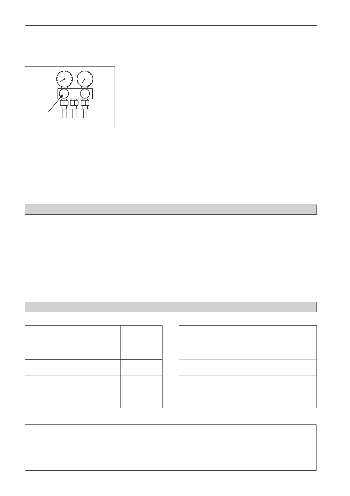
! Caution
• Manifold Gauge will show cylinder pressure rather than suction pressure if the cylinder valve and Manifold
valve “A” are both open.
There are many ways of charging liquid in a “controlled manner” into the suction
side:-
1. Use valve A on the manifold gauge set
2. Use the valve on the refrigerant cylinder
3. Charge through a Shredder valve
4. Use a hose with a Shredder valve depressor
A
2. Charging procedures – Three phase compressors
The fundamental procedure is the same as for single phase models but the compressor can run in the wrong direction on
starting. If this happens reverse any two phases and start again. Short term reverse rotation will not damage the compressor.
All Specter compressors (Model: ZR90 to ZR19M) have internal discharge temperature protectors which are very effective
in preventing dangerously high discharge temperatures during charging. The protection module will trip and lock the
compressor out for 30 minutes. It is not normally necessary to wait 30 minutes for the module to reset. When the compressor
has cooled down the module can be reset by breaking the power supply to the control circuit. Very often the serviceman
does not understand why the module tripped and uses a jumper wire to bypass it. He continues to charge the system and
removes the jumper when charging is complete. The compressor may or may not run with the protector back in the circuit
but it is certain that the compressor has been damaged and premature failure is inevitable.
5. Charge into the suction side at some distance from the compressor
6. All of the above
OVERALL CHECKING
Ensure the following, in particular:-
1) The unit is mounted solidly and rigid in position.
2) Piping and connections are leak proof after charging.
3) Proper wiring has been done.
Drainage check:- Pour some water into left side of drain
pan (drainage are in right side of unit).
• Test run:
1) Conduct a test run after water drainage test and gas
leakage test.
STANDARD OPERATING CONDITION
Cooling Only Unit
Temperature Ts °C / °F Th °C / °F
Minimum indoor
temperature
Maximum indoor
temperature
Minimum outdoor
temperature
Maximum outdoor
temperature
19.4 / 66.9 13.9 / 57.0
26.7 / 80.1 19.4 / 66.9
19.4 / 66.9 13.9 / 57.0
46 / 114.8 24 / 75.2
2) Watch out for the following:a) Is the electric plug firmly inserted into the socket?
b) Is there any abnormal sound from unit?
c) Is there smooth drainage of water?
• Check that:
1) Condenser fan is running, with warm air blowing off the
condensing unit.
2) Evaporator blower is running and discharge cool air.
3) The remote controller incorporates a 3 minute delay in
the circuit. Thus, it requires about 3 minutes before the
outdoor condensing unit can start up.
Heat Pump Unit
Temperature Ts °C / °F Th °C / °F
Minimum indoor
temperature
Maximum indoor
temperature
Minimum outdoor
temperature
Maximum outdoor
temperature
10 / 50 -
26.7 / 80.1 -
-8 / 17.6 -9 / 15.8
24 / 75.2 18 / 64.4
Ts: Dry bulb temperature. Th: Wet bulb temperature.
! Warning
• Disconnect from the main power supply before servicing the air conditioner unit.
• DO NOT pull out the power cord when the power is ON. This may cause serious electrical shocks which may
result in fire hazards.
1-12
Page 19

AUTO RANDOM RE-START FUNCTION
If there is a power cut when the unit is operating, it will automatically resume the same operating mode when the power is
restored. (Applicable only to units with this feature).
! Caution
Before turning off the power supply, set the remote controller’s ON/OFF switch to the “OFF” position to prevent the
nuisance tripping of the unit.
If this is not done, the unit’s fans will start turning automatically when power resumes, posing a hazard to service
personnel or the user.
SERVICE AND MAINTENANCE
Service Parts
Indoor Air Filter
Indoor Unit
Maintenance Procedures
1. Remove any dust adhered on the filter by using a vacuum
cleaner or wash in lukewarm water (below 40°C) with neutral
cleaning detergent.
2. Rinse well and dry the filter before placing it back onto the
unit.
3. Do not use gasoline, volatile substances or chemical to clean
the filter.
1. Clean any dirt or dust on the grille or panel by wiping it using
soft cloth soaked in lukewarm water (below 40°C) with
neutral detergent solution.
2. Do not use gasoline, volatile substances or chemical to clean
the indoor unit.
Period
At least once
every 2 week.
More frequently if
necessary.
At least once
every 2 weeks.
More frequently if
necessary.
English
Condense Drain Pan & Pipe
Indoor Fan
Indoor/Outdoor Coil
Power Supply
Compressor
Compressor Oil
Fan Motor Oil
1. Check its cleanliness and clean it if necessary.
1. Check for any abnormal noise.
1. Check and remove any dirt clogged between the fins.
2. Check and remove any obstacles that hinder air flowing into
and out of the indoor/outdoor unit.
1. Check the voltage and current of the indoor and outdoor unit.
2 Check the electrical wiring for any faulty contacts caused by
loose connections, foreign matters, etc. Tighten the wires onto
the terminal block if necessary.
1. No maintenance needed if the refrigerant circuit remain sealed.
However, check for any refrigerant leaks at all joints and
fitting.
1. The compressor oil is factory-precharged. It is not necessary
to add any oil if the circuit remains sealed.
1. All motor pre-lubricated and sealed at factory.
Every 3 months.
When necessary.
Every month.
Every month.
Every 2 months.
Every 2 months.
Every 6 months.
No maintenance
required.
No maintenance
required.
! Caution
Do not operate any heating apparatus too close to the air conditioner unit. This may cause the plastic panel to melt or
deform as a result of the excessive heat.
1-13
Page 20

TROUBLESHOOTING
When any malfunction of the air conditioner unit is noted, immediately switch off the power supply to the
unit. Check the following fault conditions and causes for some simple troubleshooting tips.
Fault
1. The compressor does not start operate after 3 minutes
from starting the air conditioner unit.
2. The air conditioner unit does not operate.
3. The air flow is too low.
4. The remote control display is dim.
5. Discharge air flow has bad odor.
6. Condensation on the front air grille of the indoor unit.
Causes
- Protection against frequent starting. Wait for 3 to 4
minutes for the compressor to start operate.
- Power failure, or the fuse need to be replaced.
- The power plug is disconnected.
- It is possible that your delay timer has been set incorrectly.
- If the fault persist after all these verifications, please
contact the air conditioner unit installer.
- The air filter is dirty.
- The doors or windows are open.
- The air suction and discharge are clogged.
- The regulated temperature is not high enough.
- Battery flat.
- The batteries are placed incorrectly.
- Odors may be caused by cigarettes, smoke particles,
perfume etc. which might have adhered onto the coil.
- This is caused by air humidity after an extended long
period of operation.
- The set temperature is too low, increase the temperature
setting and operate the unit at high fan speed.
7. Water flowing out from the air conditioner unit.
8. Hissing air flow sound from the air conditioner unit
during operation.
- Check the condensate evacuation.
- Refrigerant fluid flowing into the evaporator coil.
If the fault persists, please call your local dealer / serviceman.
1-14
Page 21

MANUEL D’INSTALLATION
Ce manuel fournit les procédures d’installation pour assurer le bon fonctionnement et la sécurité de cet appareil.
Des ajustements peuvent être nécéssaires pour suivre les réglementations locales.
Avant d’installer et de faire fonctionner le climatiseur, lisez attentivement ce manuel et conservez le.
CLIMATISEUR MASQUÉ AU PLAFOND, TYPE DIVISÉ
MODÉLE
Français
UNITÉ FROID SEUL
CC10C / ACC10C
SL10B / ALC10B
SL10C / ALC10C
4SL10B / A4LC10B
5SL10C / A5LC10C
CC15C / ACC15C
SL15B / ALC15B
SL15C / ALC15C
4SL15B / A4LC15B
5SL15C / A5LC15C
CC20C / ACC20C
SL20B / ALC20B
4SL20B / A4LC20B
5SL20B / A5LC20B
CC25C / ACC25C
SL25B / ALC25B
4SL25B / A4LC25B
5SL25B / A5LC25B
CC28C / ACC28C
SL30B / ALC30B
SL30C / ALC30C
4SL30C / A4LC30C
5SL30C / A5LC30C
CC30C / ACC30C
SL30B / ALC30B
SL30C / ALC30C
4SL30C / A4LC30C
5SL30C / A5LC30C
CC38C / ACC38C
SL40C / ALC40C
4SL40C / A4LC40C
5SL40C / A5LC40C
CC40C / ACC40C
SL40C / ALC40C
4SL40C / A4LC40C
5SL40C / A5LC40C
CC50C / ACC50C
SL50C / ALC50C
4SL50C / A4LC50C
5SL50C / A5LC50C
CC60C / ACC60C
SL60C / ALC60C
4SL60C / A4LC60C
5SL60C / A5LC60C
MSS60C / AMC60C
POMPE À CHALEUR
CC10CR / ACC10CR
SL10BR / ALC10BR
SL10CR / ALC10CR
4SL10BR / A4LC10BR
5SL10CR / A5LC10CR
CC15CR / ACC15CR
SL15BR / ALC15BR
SL15CR / ALC15CR
4SL15BR / A4LC15BR
5SL15CR / A5LC15CR
CC20CR / ACC20CR
SL20BR / ALC20BR
4SL20BR / A4LC20BR
5SL20BR / A5LC20BR
CC25CR / ACC25CR
SL25BR / ALC25BR
4SL25BR / A4LC25BR
5SL25BR / A5LC25BR
CC28CR / ACC28CR
SL30BR / ALC30BR
SL30CR / ALC30CR
4SL30CR / A4LC30CR
5SL30CR / A5LC30CR
CC30CR / ACC30CR
SL30BR / ALC30BR
SL30CR / ALC30CR
4SL30CR / A4LC30CR
5SL30CR / A5LC30CR
CC38CR / ACC38CR
SL40CR / ALC40CR
4SL40CR / A4LC40CR
5SL40CR / A5LC40CR
CC40CR / ACC40CR
SL40CR / ALC40CR
4SL40CR / A4LC40CR
5SL40CR / A5LC40CR
CC50CR / ACC50CR
SL50CR / ALC50CR
4SL50CR / A4LC50CR
5SL50CR / A5LC50CR
CC60CR / ACC60CR
SL60CR / ALC60CR
4SL60CR / A4LC60CR
5SL60CR / A5LC60CR
MSS60CR / AMC60CR
Part No.: A08019025456
IM-CCC-0501(3)-Acson
2-1
Page 22

SOMMAIRE
- Contour et Dimensions page i-iv
- Précautions de Sécurité page 2
- Diagramme d’Installation page 3
- Installation de l’Unité Intérieure page 3
- Installation de l’Unité Extérieure page 4
- Tuyauteries Frigorifiques page 4
- Raccordement Electrique page 5
- Précautions Spéciales en Traitant l'Unité de R410A page 9
- Précautions Spéciales en Traitant l'Unité de R407C page 9
- Purge de la Tuyauterie de Réfrigérant page 9
- Aspiration et Chargement page 10
- Précautions Spéciales Lors du Chargement D'un Appareil À Compresseurs Scroll de Copeland page 11
- Vérifications Générales page 12
- Conditions Standard de Fonctionnement page 12
- Fonction de Redemarrage au Hasard Automatique page 13
- Entretien et Maintenance page 13
- Analyse des Causes de Dysfonctionnement page 14
PRÉCAUTIONS DE SÉCURITÉ
Avant de faire fonctionner l'appreil, veuillez bien lire les précautions de sécurité suivantes.
! Attention
• L'installation et la maintenance doivent être exécutées par une personne qualifiée qui est familiarisée avec les lois
et réglementations en vigueur, et aussi expérimentée dans ce type d'équipements.
• Tous les câblages doivent répondre aux réglementations électriques nationales.
• Avant de commencer le raccordement suivant le schéma électrique, s’assurer que la tension nominale de l’appareil
corresponde bien à celle indiquée sur la plaque signalétique.
• L' unité doit être raccordée à la TERRE pour prévenir tous les risques possibles dûes à un défaut d'isolation.
• Aucun câble électrique ne doit toucher la tuyauterie du réfrigérant, le compresseur ou les pièces mobiles des moteurs
de ventilation.
• Avant l’installation ou l’entretien du climatiseur, s’assurer que l’appareil est éteint (OFF).
IMPORTANT
NE PAS INSTALLER OU UTILISER LE CLIMATISEUR DANS UNE BUANDERIE.
! Avertissement
Vérifier les points suivants au cours de l’installation.
• Ne pas installer l'appareil où il peut se produire des fuites de gaz inflammable.
En cas de fuite et accumulation de gaz autour de l’appareil, il y a risque d’incendie.
• S’assurer que le tuyau d’évacuation du condensat est correctement branché.
Si le tuyau d’évacuation n’est pas correctement branché, les éventuelles fuites d’eau risquent de mouiller
le mobilier.
• Ne pas surcharger l'unité (en fluide frigorigène).
Cet appareil est préchargé en usine. Une charge trop importante risque de provoquer une surcharge
électrique ou d’endommager le compresseur.
• S’assurer que le panneau supérieur de l’appareil est remis en place après l’installation ou l’entretien.
Avec un panneau mal fixé l’appareil va fonctionner bruyamment.
2-2
Page 23
Unité Intérieure
Reprise d’air
DIAGRAMME D’INSTALLATION
Français
Tuyauteries Frigorifiques
Reprise d’air
Ventilateur
INSTALLATION DE L’UNITÉ INTÉRIEURE
L’appareil d’intérieur doit être installé de manière à ce qu’il
n’y ait pas de court-circuit de la décharge froide. Respectez
l’espace libre d’installation. Ne placez pas l’appareil
d’intérieur là où la lumière solaire tomberait directement sur
lui. L’emplacement est convenable pour la tuyauterie et le
drainage et il doit y avoir une grande distance entre une porte
et l’appareil.
Assemblage Dissimulé au Plafond
– Utilisez le crochet de suspension fourni avec l’appareil.
– Veillez à ce que le mur soit suffisamment solide pour
soutenir le poids.
Distance du centre de l’essieu (voir le croquis ci-dessous)
A
Unité Extérieure
CC A mm (pouces) L mm (pouces)
10 C/CR 741 (29,2) 225 (8,9)
15 C/CR 881 (34,7) 225 (8,9)
20 C/CR 1041 (41,0) 225 (8,9)
25 C/CR 1176 (46,3) 225 (8,9)
28 C/CR 959 (37,8) 339 (13,3)
30 C/CR 956 (37,6) 266 (10,5)
38 C/CR 1264 (49,8) 401 (15,8)
40 C/CR 1076 (42,4) 266 (10,5)
50 C/CR 1326 (52,2) 266 (10,5)
60 C/CR 1526 (60,1) 266 (10,5)
Laissez de l’espace pour faciliter le service et pour un
courant d’air optimal, tel qu’indiqué dans le diagramme.
10 mm (32,8)
L
10 mm (32,8)
2-3
Page 24
INSTALLATION DE L'UNITÉ EXTÉRIEURE
L’unité extérieure doit être installée de manière à ce qu’il n’y ait
pas de court-circuit de l’air de rejet ni d’obstruction au passage
régulier de l’air. Respecter l’espace libre d’installation indiqué dans
le tableau. Choisir l’emplacement le plus frais possible où
l’admission d’air ne soit pas plus élevée que la température
extérieure (maximum 45°C).
Veiller à ce qu’il n’y ait pas d’obstruction au courant d’air entrant
et sortant de l’appareil. Enlever tous les obstacles susceptibles de
bloquer l’admission ou le rejet de l’air.
Dégagement de l'unitérieure séries SL (dans mm)
300 1000
Refoulement
Entrée d’Air
Obstacle
Obstacle
L’emplacement doit être bien ventilé, afin que l’unité puisse aspirer
et distribuer plein d’air en abaissant la température.
L’emplacement doit pouvoir supporter le poids de l’unité extérieure
et isoler du bruit et des vibrations.
L’emplacement doit être protégé de la lumiére directe du soleil.
Installer un auvent si nécessaire.
L’emplacement ne doit pas être trop exposé à la poussière ou aux
vapeurs d’huile, de sel ou de souffre.
TUYAUTERIES FRIGORIFIQUES
Longueur Maxi des Tuyauteries et Nombre Maxi
de Coudes
Lorsque le conduit est trop long, la capacité et la fiabilité diminuent.
La résistance du système de conduits au flux de liquide réfrigérant
augmente avec le nombre de plis, ce qui diminue sa capacité de
réfrigération. Choisir toujours le cheminement le plus court et
suivre la recommandation indiquée ci dessous:
Modéle
Données
Longueur max, A m (pieds)
Elevation max, B m (pieds)
Nombre de coude max, C 10 10 10 10 10
10 15 20 25 28
12 12 15 15 35
(39,4) (39,4) (49,2) (49,2) (114,8)
558810
(16,4) (16,4) (26,2) (26,2) (32,8)
300
Entrée d’Air
Obstacle
500
Accés
de Service
Obstacle
Remarques :- En cas d’obstacles de part et d’autre de l’unité d’une
hauteur supérieure à 2 mètres ou toute obstruction
d’air sur le dessus de l’unité, augmenter
sensibelment les dégagements minimum prévus.
A
C
B
Modéle
Données
Longueur max, A m (pieds)
Elevation max, B m (pieds)
30 38 40 50 60
35 35 35 35 35
(114,8) (114,8) (114,8)(114,8) (114,8)
10 10 10 10 10
(32,8) (32,8) (32,8) (32,8) (32,8)
Nombre de coude max, C 10 10 10 10 8
Remarque : Avec l’unité de réfrigération CC60C, il est
recommandé d’ajouter une bouteille tampon
externe de 6 kg.
2-4
C
A
B
C
Page 25
Travail Des Tuyaueries Et Technique Flare
Ne pas utiliser de tuyauterie de cuivre contaminé ou endommagé.
Si de la tuyauterie, un évaporateur ou un condensateur a été exposé
ou a été ouvert pendant 15 secondes, passer le système à l’aspirateur.
En général, ne pas retirer le plastique, les prises de caoutchouc et
les écrous de cuivre des soupapes, des raccords, de la tuyauterie et
des bobines jusqu’à ce qu’ils soient prêts à être installés.
Si l’on doit effectuer un travail de soudage, s’assurer que le
nitrogène passe par les tuyauteries et les raccords pendant que le
travail de soudage est effectué. Cela éliminera la formation de suie
sur les parois internes des tuyauteries de cuivre.
Couper les tuyaux progressivement, en faisant avancer la lame du
coupe-tube lentement. Une coupe profonde et forcée va déformer
le tube davantage et ainsi causer plus de bavures.
Retirer les ébarbures des rebords de tuyauterie coupés avec un
ébarbeur , tel que montré à la Figure. R. Cela évitera l’irrégularité
sur la face évasée qui cause des fuites de gaz. Tenir le tuyau en
haut et l’ébarbeur à une position plus basse pour éviter que des
morceaux de métal n’entrent dans le tuyau .
Relier les écrous ‘flare’ montés sur les connexions des unités
intérieure et extérieure aux tubes de cuivre.
La longueur exacte de tube dépassant de la dudgonnière dépend
du type de dudgonnière utilisé.
Placer le tube fermement dans la dudgeonnière. Aligner les côtés
dé et pilon de la dudgeonnière, puis serrer le pilon au maximum.
Coupe des Tubes Cuivre
Raccordement Frigorifique
Aligner les tubes et serrer l’écrou à la main d’abord.
Enfin, serrer l’écrou à l’aide d’une clef dynamométrique jusqu’au
clic.
En serrant l’écrou avec la clef dynamométrique, veiller à respecter
le sens de la flèche indiqué sur la clef.
Les connections du fluide réfrigérant sont isolées par du
polyéthurane (type ARMAFLEX ou similaire).
Ø Tube, D A (mm)
Pouce mm Impérial Normal
1/4" 6,35 1,3 0,7
3/8" 9,52 1,6 1,0
1/2" 12,70 1,9 1,3
5/8" 15,88 2,2 1,7
3/4" 19,05 2,5 2,0
Tubes Talle, mm (pouce) Couple (Nm)
6,35 (1/4) 18
9,53 (3/8) 42
12,7 (1/2) 55
15,88 (5/8) 65
19,05 (3/4) 78
Raccord à Visser
Tube Avec Dudgeon
Français
1/4t
Tube Cuivre
Figure R
Ebavurage
Dudgeonnière
!
Tube Cuivre
Avertissement
Tube de l’Unité Intérieure
Clef d’Immobilisation
Ecrou
Clef Dynamométrique
RACCORDEMENT ELECTRIQUE
S’assurer que les couleurs des câbles de l’unité extérieure et les repères
du bornier soient les mêmes que sur l’unité intérieure.
Unités Réfrigérantes Seulement, CC 10 /15 /20 /25 C
Unité Intérieure CC 10C CC 15C CC 20C CC 25C
Unité Extérieure SL 10B SL 15B SL 20B SL 25B
Tension d’alimentation**
220V–240V /1Ph /50Hz + ! ou 208V–230V /1Ph /60Hz + !
Fusible aM* A 10 10 16 20
Section du câble d’alim* mm
2
1,5 1,5 2,5 2,5
Nombre de conducteurs 33 33
Section du câble de liaison* mm
2
1,5 1,5 2,5 2,5
Nombre de conducteurs 33 33
2-5
Page 26
CC 10 / 15 / 20 / 25 C - SL 10 / 15 / 20 / 25 B
CC 28 / 30 C - SL 30 B
COMP
L
COMP
N
Bornier de L’Unité
Extérieure
Bornier de L’Unité
Intérieure
N
N
Cordon
Electrique
Il doit y avoir un intereuptuer à double pöles avec un
intervalle de contact de 3 mm minimum et un coupe-
!
curcuit /fusible comme recommandé dans le circuit
d'installation fixe.
Unités Réfrigérantes Seulement, CC 28 / 30 C
Unité Intérieure CC 28 / 30C
Unité Extérieure SL 30B SL30C
Tension d’alimentation** 220V – 240V/1Ph /50Hz + ! ou 208V–230V /1Ph /60Hz + !
Fusible aM* A 25 25
Section du câble d’alim* mm
2
4,0 4,0
Nombre de conducteurs 33
Section du câble de liaison* mm
2
2,5 2,5
Nombre de conducteurs 34
CC 28 / 30 C - SL 30 C
L
Bornier de L’Unité
Extérieure
N
!
S
Bornier de
L’Unité Intérieure
COMP
L
N
N
R
Il doit y avoir un intereuptuer à double pöles
avec un intervalle de contact de 3 mm minimum
!
et un coupe-curcuit /fusible comme
!
!
Cordon Electrique
COMP
L
N
!
recommandé dans le circuit d'installation fixe.
Unités Réfrigérantes Seulement, CC 38 / 40 / 50 / 60 C
Unité Intérieure CC38 / 40C CC 50C CC 60C
Unité Extérieure SL 40C SL 50C SL 60C ou MSS 60C
Tension d’alimentation**
380V– 415V/ 3Ph/ 50Hz +N + ! ou 208V–230V /3Ph /60Hz + N + !
Fusible aM* (50/60Hz) A 10/20 16/25 16/25
Section du câble d’alim* (50/60Hz) mm
2
1,5/2,5 2,5/4,0 2,5/4,0
Nombre de conducteurs 55 5
Section du câble de liaison* (50/60Hz) mm
2
1,5/1,5 1,5/1,5 1,5/1,5
Nombre de conducteurs 44 4
IMPORTANT: * Ces valeurs sont données à titre indicatif seulement; elles doivent être vérifiées et ajustées en fonction des
normes et de la réglementations en vigueur. Elles dépendent aussi du type d’installation et du choix des
conducteurs utilisés.
** Le voltage adéquat doit être vérifié avec les données de l’étiquette sur l’appareil. ETL n’est applicable
que pour une alimentation électrique de 60Hz.
2-6
Page 27
CC 38 / 40 / 50 / 60 C - SL 40 / 50 / 60 C
COMP
L
N
Bornier de
L’Unité Intérieure
COMP
L
N
!
!
Il doit y avoir un intereuptuer à double pöles
!
avec un intervalle de contact de 3 mm
minimum et un coupe-curcuit /fusible
comme recommandé dans le circuit
d'installation fixe.
Unités De Pompe à Chaleur, CC10 / 15 / 20 / 25 CR
Unité Intérieure CC 10CR CC 15CR CC 20CR CC 25CR
Unité Extérieure SL 10BR SL 15BR SL 20BR SL 25BR
Tension d’alimentation**
Fusible aM* A 10 10 16 20
Section du câble d’alim* mm
2
Nombre de conducteurs 33 33
Section du câble de liaison* mm
2
Nombre de conducteurs 55 55
Cordon Electrique
220V – 240V/1Ph/50Hz + ! ou 208V–230V /1Ph /60Hz + !
1,5 1,5 2,5 2,5
1,5 1,5 2,5 2,5
Bornier de L’Unité
Extérieure
R
S
T
N
!
Français
CC 10 / 15 / 20 / 25 CR - SL 10 / 15 / 20 / 25 BR
Sonde de L’Unité Extérieure
4WV
OF
COMP
Bornier de
L’Unité Intérieure
L
N
N
!
!
Unités De Pompe à Chaleur, CC 28 / 30 CR
Cordon Electrique
Bornier de L’Unité
4WV
Extérieure
OF
COMP
N
!
!
Il doit y avoir un intereuptuer à double pöles
avec un intervalle de contact de 3mm minimum
et un coupe-curcuit /fusible comme recommandé
dans le circuit d'installation fixe.
Unité Intérieure CC 28/30 CR
Unité Extérieure SL 30BR SL 30CR
Tension d’alimentation** 220V – 240V/1Ph/50Hz + !
ou 208V–230V /1Ph /60Hz + !
Fusible aM* A 25 25
Section du câble d’alim* mm
2
4,0 4,0
Nombre de conducteurs 33
Section du câble de liaison* mm
2
2,5 2,5
Nombre de conducteurs 56
IMPORTANT: * Ces valeurs sont données à titre indicatif seulement; elles doivent être vérifiées et ajustées en fonction des
normes et de la réglementations en vigueur. Elles dépendent aussi du type d’installation et du choix des
conducteurs utilisés.
** Le voltage adéquat doit être vérifié avec les données de l’étiquette sur l’appareil. ETL n’est applicable que
pour une alimentation électrique de 60Hz.
2-7
Page 28
CC 28 / 30 CR - SL 30 BR
Il doit y avoir un intereuptuer à double
!
pöles avec un intervalle de contact de
3 mm minimum et un coupe-curcuit
/fusible comme recommandé dans le
circuit d'installation fixe.
Bornier de
L’Unité
Intérieure
A
4WV
OF
COMP
L
N
N
!
!
Sonde de L’Unité Extérieure
4WV
OF
COMP
N
!
Cordon Electrique
Bornier de L’Unité
Extérieure
CC 28 / 30 CR - SL 30 CR
Sonde de L’Unité Extérieure
A
Il doit y avoir un intereuptuer à
!
double pöles avec un intervalle de
contact de 3 mm minimum et un
coupe-curcuit /fusible comme
recommandé dans le
circuit d'installation fixe.
Bornier de
L’Unité
Intérieure
4WV
OF
COMP
L
N
N
!
!
Cordon Electrique
A
4WV
OF
Bornier de L’Unité
COMP
Extérieure
L
N
!
L
N
!
Unités de pompe à chaleur, CC 38 / 40 / 50 / 60 CR
Unité Intérieure
Unité Extérieure
Tension d'alimentation**
380V– 415V /3Ph /50Hz +N + ! ou 208V – 230V /3Ph /60Hz + N + !
Fusible aM* (50/60Hz) A 10/20 16/25 16/25
Section du câble d'alim* (50/60Hz) mm
Nombre de conducteurs 55 5
Section du câble de liaison* (50/60Hz) mm
Nombre de conducteurs 77 7
CC 38 / 40CR CC 50CR CC 60CR
SL 40CR SL 50CR SL 60CR ou MSS 60CR
2
2
1,5/2,5 2,5/4,0 2,5/4,0
1,5/1,5 1,5/1,5 1,5/1,5
CC 38 / 40 / 50 / 60 CR - SL 40 / 50 / 60 CR
Il doit y avoir un intereuptuer à double
!
pöles avec un intervalle
de contact de 3 mm minimum et
un coupe-curcuit /fusible comme
recommandé dans le circuit d'installation
fixe.
Bornier de
L’Unité
Intérieure
A
4WV
OF
COMP
L
N
!
Cordon Electrique
Sonde de L’Unité Extérieure
A
4WV
OF
COMP
L
Bornier de L’Unité
Extérieure
N
!
R
S
T
N
!
IMPORTANT: * Ces valeurs sont données à titre indicatif seulement; elles doivent être vérifiées et ajustées en fonction des normes et
de la réglementations en vigueur. Elles dépendent aussi du type d’installation et du choix des conducteurs utilisés.
** Le voltage adéquat doit être vérifié avec les données de l’étiquette sur l’appareil. ETL n’est applicable
que pour une alimentation électrique de 60Hz.
2-8
Page 29

! Avertissement
S’assurer que les couleurs des câbles de l’unité extérieure et les repères du bornier soient les mêmes que sur
l’unité intérieure.
PRÉCAUTIONS SPÉCIALES EN TRAITANT L'UNITÉ DE R410A
R410A est un nouveau réfrigérant de HFC qui n'endommage
pas la couche d'ozone. La pression d'utilisation de ce nouveau
réfrigérant est 1.le réfrigérant 6 fois plus haut que
conventionnel (R22), ainsi installation/servicing approprié est
essentiel.
• Jamais réfrigérant de l'utilisation autre que R410A dans
un climatiseur qui est conçu pour fonctionner avec R410A.
• De l'huile de POE est employée comme lubrifiant pour le
copressor de R410A, qui est différent de l'huile minérale
utilisée pour le compresseur R22. Pendant l'installation
ou l'entretien, la précaution supplémentaire doit être prise
pour ne pas exposer le système de R410A trop long à l'air
moite. L'huile résiduelle de POE dans la tuyauterie et le
cn de composants absorbent l'humidité de l'air.
• Pour empêcher mischarging, le diamètre du port de ser-
vice sur la valve de fusée est différent de celui de R22.
PRÉCAUTIONS SPÉCIALES EN TRAITANT L’UNITÉ DE R407C
• R407C est un mélange réfrigérant zeotropic qui a le
potentiel nul d'épuisement de l’ozone et conforme ainsi
au règlement de protocole de Montréal. Il exige l’huile de
l’huile d’ester de polyol (POE) pour le lubrifiant de son
compresseur. Sa capacité et exécution réfrigérantes sont
plus ou moins comme le réfrigérant R22.
• De l’huile de POE est employée comme lubrifiant pour le
compresseur de R407C, qui est différent de l’huile minérale
utilisée pour le compresseur R22. Pendant l’installation
ou l’entretien, la précaution supplémentaire doit être prise
pour ne pas exposer le système de R407C trop long à l’air
moite. L’huile résiduelle de POE dans la tuyauterie et les
composants peuvent absorber l’humidité de l’air.
• Le réfrigérant R407C plus facilement est affecté par la
poussière de l’humidité comparée à R22, veillent à couvrir
temporairement les extrémités de la tuyauterie avant
l’installation.
• Employez les outils et les matériaux exclusivement pour
le réfrigérant R410A. Les outils exclusivement pour
R410A sont valve diverse, tuyau de remplissage, indicateur
de pression, détecteur de fuite de gaz, outils de fusée, clé
dynamométrique, pompe de vide et cylindre de réfrigérant.
• Car un climatiseur de R410A encourt une pression plus
élevée que les unités R22, il est essentiel de choisir les
pipes de cuivre correctement. Jamais diluant de cuivre de
pipes d'utilisateur que 0,8mm quoiqu'ils soient disponibles
sur le marché.
• Si le gaz de réfrigérant fuit pendant l'installation /servic-
ing, soyez sûr d'aérer entièrement. Si le gaz réfrigérant
entre en contact avec le feu, un gaz toxique peut se produire.
• En installant ou en enlevant un climatiseur, ne laissez pas
l'air ou l'humidité rester dans le cycle réfrigérant.
• Aucune charge additionnelle d’huile de compresseur n’est
autorisée.
• Aucun autre réfrigérant autre que R407C.
• Outils spécifiquement pour R407C seulement (ne doit pas
être employé pour R22 ou tout autre réfrigérant)
i) Mesure diverse et tuyau de remplissage
ii) Détecteur de fuite de gaz
iii) Cylindre réfrigérant de cylinder/charging
iv) Adapteur de la pompe de vide c/w
v) Outils de fusée
vi) Machine réfrigérante de rétablissement
• Le Filtre-dessiccateur doit être installé suivant la ligne
liquide pour tous les climatiseurs de R407C. Ce doit
réduire au minimum la contamination de l’humidité et de
la saleté dans le système réfrigérant.le Filtre-dessiccateur
doit être de type de passoir moléculaire. Pour un système
de heat-pump, installez un dessiccateur bi-directionnel de
filtre d’écoulement suivant la ligne liquide.
Français
PURGE DE LA TUYAUTERIE DE RÉFRIGÉRANT
Purge Des Tuyauteries Et De l’unité Intérieure
Excepté l’unité extérieure (groupe de condensation) qui
contient la charge complète de réfrigérant, l’unité intérieure
et les tubes des liaisons frigorifiques doivent être purgés de
l’air contenu dans le circuit.
L’unité de l’extérieur est équipée de trois valves connectées
de réfrigération. La valve de suction est la plus large tandis
que la petite est la valve de liquide. Les deux valves sont
fournies d’orifice de soupape pour connecter avec un
manomètre.
• Enlever le bouchon central, ainsi que le bouchon de la
prise de pression sur chaque vanne.
• Raccorder le centre de la jauge de chargement à la pompe
à vide.
• Raccorder la jauge de chargement à l’orifice de service de
la valve à trois voies.
• Faites démarrer la pompe à vide. Vérifiez que le manomètre
de pression d’admission indique 0,9 bar. Le temps
d’évacuation varie avec la capacité de chaque pompe à
vide, mais généralement en une demi-heure.
• Fermez la valve d`admission et arrêtez la pompe à vide.
• Sur l’unité de l’extérieur, ouvrez l’aspiration et la valve
de liquide (dans le sens contraire des aiguilles de montre),
avec une clé pour vis hexagonales.
• L’unité de climatisation est prête à fonctionner.
• Si la lecture est proche de zéro, le circuit réfrigérant doit
être évacué (par une pompe à vide) et chargé à nouveau.
Flexible
D’Alimentation
Prise De
Pression
Tuyauteries
Frigorifiques
Ecrou
Unité Extérieure
Vanne 3 Voies
2-9
Ouverture
Vanne Avec
Clef Allen d
4 mm
Page 30
Unité Extérieure
Vanne
Liquide
Tuyauteries
Frigorifiques
Manométer
Vanne
D’Aspiration
Basse Pression
Manifold
Flexible D’Alimentation
ASPIRATION ET CHARGEMENT
Unité Intérieure
Manomèter
Haute Pression
Pompe à Vide
La charge complète de gaz se trouve dans l’unité extérieure,
jusqu’à une longueur nominale de 5 mètres, aucun
complément de charge n’est nécéssaire. Si la longueur de la
liaison est supérieure à 5 m, utilisez alors la valve de charge
supplémentaire comme indiqué dans le tableau ci-dessous.
Opération De Aspiration Et Chargement
Cette opération nécessite impérativement l’utilisation d’un
cylindre de charge ou une balance de précision. Le
complement de charge se fait sur l’unité extérieure par la
vanne d’aspiration via la prise de pression de la vanne de
service.
• Enlever le bouchon de la vanne de service.
• Connectez le collecteur de pression basse à l’orifice
d’aspiration, le collecteur central au réservoir (voir le
croquis ci-dessous).
Purgez tous les tuyaux flexibles avec un gaz réfrigérant.
• Mettre le climatisateur en marche.
• Ouvrir le cylindre de gaz et la valve de chargement de
basse pression.
• Lorsqu’une quantité suffisante de réfrigérant est injectée
dans l’unité, fermer le côté basse pression et la valve du
cylindre de gaz.
• Débrancher le tuyau de service de l’orifice de service.
Remettre le bouchon de l’orifice de service.
Tableau de complément de charge en grammes
(Module Pompe à Chaleur) (R410A)
Modèle 7 m 10 m 15 m 20 m
CC 10CR 36 90 – –
CC 15CR 36 90 – –
CC 20CR 45 112 225 –
CC 25CR 90 225 450 –
CC 28CR / CC 30CR 90 225 450 675
CC 38CR / CC 40CR 90 225 450 675
CC 50CR 90 225 450 675
CC 60CR 90 225 450 675
Tableau de complément de charge en grammes
(Module Refroidisseur) (R22/R407C)
Modèle 7 m 10 m 15 m 20 m
CC 10C 30 75 – –
CC 15C 30 75 – –
CC 20C 30 75 150 –
CC 25C 76 190 380 –
CC 28C / CC 30C 100 250 500 750
CC 38C / CC 40C 100 250 500 750
CC 50C 100 250 500 750
CC 60C 100 250 500 750
Tableau de complément de charge en grammes
(Module Refroidisseur) (R410A)
Modèle 7 m 10 m 15 m 20 m
CC 10C 27 67 – –
CC 15C 27 67 – –
CC 20C 27 67 135 –
CC 25C 68 171 342 –
CC 28C / CC 30C 90 225 450 675
CC 38C / CC 40C 90 225 450 675
CC 50C 90 225 450 675
CC 60C 90 225 450 675
Tableau de complément de charge en grammes
(Module Pompe à Chaleur) (R22/R407C)
Modèle 7 m 10 m 15 m 20 m
CC 10CR 40 100 – –
CC 15CR 40 100 – –
CC 20CR 50 125 250 –
CC 25CR 100 250 500 –
CC 28CR / CC 30CR 100 250 500 750
CC 38CR / CC 40CR 100 250 500 750
CC 50CR 100 250 500 750
CC 60CR 100 250 500 750
2-10
Page 31

Vérifiez la fuite du réfrigérant
Vérifiez avec un détecteur pour réfrigérant, pour voir s’il y a une fuite dans la connexion de type élargi de l’unité intérieure.
Suggestions : Après fonctionnement de l’unité pendant un certain temps, vérifiez s’il y a des traces d’huile, il y a une fuite.
Unité Extérieure
Tuyauteries
Vanne
Liquide
Vanne
D’Aspiration
Frigorifiques
Manométer
Basse Pression
Manifold
Flexible D’Alimentation
Unité Intérieure
Manomèter Haute Pression
Reservoir De Gas Refrigérant
Français
PRÉCAUTIONS SPÉCIALES LORS DU CHARGEMENT D’UN APPAREIL
À COMPRESSEURS SCROLL DE COPELAND
Ces précautions visent uniquement les compresseurs Scroll de Copeland avec des frigorigènes R22, R407C, R134A, R404A,
R507 et R410A et non pas les compresseurs à piston Copeland ou les compresseurs à volute concurrents.
Les compresseurs Scroll ont une efficacité volumétrique très élevée et pompent rapidement un vide profond si l’appareil
manque de frigorigène ou si l’adduction de frigorigène est trop lente. Le fonctionnement à pression d'aspiration basse génère
vite des températures de refoulement très élevées. Pendant ce temps, les volutes ne sont pas bien lubrifiées, car leur lubrification
dépend du brouillard d'huile dans le frigorigène. Un graissage insuffisant entraîne une grande friction entre les faces et les
extrémités des volutes, ce qui produit encore plus de chaleur. La chaleur de compression combinée à la chaleur découlant de
la friction accrue se concentre dans une zone de refoulement réduite, où les températures peuvent rapidement dépasser 300°C.
Ces températures extrêmes abîment les spirales de volute et le support de volute en rotation. Cet endommagement peut se
produire en moins d’une minute, surtout dans les gros compresseurs. Il peut y avoir une panne dans les quelques premières
heures ou les dommages infligés au cours du chargement local peuvent se faire sentir un certain temps après.
Les autres défauts habituels du chargement local incluent le sous-chargement, le surchargement, la présence d’humidité ou
d’air dans le dispositif, etc. Avec le temps, chacune de ces anomalies peuvent mettre le compresseur en panne.
Il faut très peu d’équipement pour effectuer un chargement local satisfaisant :-
Jeu de manomètres de moteur Vacuomètre
Tuyaux flexibles Balances
Pompe à vide Thermomètre
Une charge de frigorigène adéquate doit correspondre au volume recommandé par le fabricant, et cette recommendation
devrait être suivie par l’installateur.
1. Méthode de chargement - compresseurs monophasés
Vider le dispositif jusqu’à l’obtention de 500 microns de mercure Hg. (67 Pa). Pour réduire le délai de purge, utiliser des
flexibles courts à grand diamètre et les raccorder à des orifices de service sans restriction de l’appareil. On ne peut pas
évaluer la qualité du vide selon le délai - il faut employer un vacuomètre fiable (vacuomètre électronique, etc.).
Tourner la bouteille de frigorigène à l’envers, purger le flexible de charge et alimenter en liquide au moyen de l’orifice de
chargement de la conduite de liquide jusqu’à ce que le frigorigène ne coule plus ou jusqu’à ce qu’une charge de poids
adéquate soit atteinte. Si une charge supplémentaire est requise, démarrer l’appareil et infiltrer lentement du liquide dans
le côté basse pression jusqu’à ce que le dispositif soit plein.
Copeland recommande de charger le liquide de façon CONTRÔLÉE dans le côté basse pression jusqu’à ce que le
dispositif soit plein. Cette recommandation ne s’applique pas aux compresseurs à piston, qui risquent d’être gravement
endommagés par le chargement de liquide dans le côté basse pression.
Surveiller attentivement les pressions d'aspiration et de refoulement - la pression manométrique d'aspiration ne doit jamais
tomber sous 25 psig (1,7 bar) au cours du chargement.
2-11
Page 32

! Avertissement
• Le manomètre du collecteur indique la pression de la bouteille au lieu de la pression d'aspiration si le robinet
de la bouteille et la soupape “A” du collecteur sont ouverts tous les deux.
Il y a bien des façons de charger le liquide de manière “contrôlée” dans le côté
basse pression:-
1. Utiliser la soupape A sur le groupe manomètre du collecteur.
2. Recourir au robinet sur la bouteille de frigorigène.
3. Charger par l’intermédiaire d’une valve Shredder.
4. Employer un flexible muni d’un dépresseur de valve Shredder.
5. Charger dans le côté basse pression à une certaine distance du compresseur.
A
2. Méthode de chargement - compresseurs triphasés
La méthode de base est la même que pour les modèles monophasés, mais le compresseur peut tourner dans la mauvaise
direction au démarrage. Si cela se produit, inverser deux phases (n’importe lesquelles) et redémarrer. Une rotation inversée
de courte durée n’endommagera pas le compresseur.
Tous les compresseurs Specter (Modéle: ZR90 à ZR19M) disposent de protections internes contre la température de
refoulement, qui préviennent très efficacement les températures de refoulement dangereusement élevées en cours de
chargement. Le module de protection se déclenchera et verrouillera les compresseurs pendant 30 minutes. Il n’est
normalement pas nécessaire d’attendre 30 minutes pour réinitialiser le module. Une fois le compresseur refroidi, le module
peut être réinitialisé en coupant l’alimentation du circuit de commande. Très souvent, le mécanicien d'entretien ne comprend
pas pourquoi le module s’est déclenché et se sert d’un cavalier pour le contourner. Il continue de charger l’appareil et retire
le cavalier à la fin du chargement. Le compresseur fonctionnera peut-être avec la protection réintégrée dans le circuit, mais
il est certain que le compresseur a été endommagé et qu’une panne prématurée est inévitable.
6. Tous les moyens ci-dessus.
VÉRIFICATIONS GÉNÉRALES
Assurez-vous en particulier les points suivants:-
1) L’appareil est solidement installé et ne bouge pas.
2) Les tuyauteries et raccords sont étanches après la
mise en charge.
3) Le câblage est fait correctement.
Vérification de l’écoulement: - Verser un peu d’eau à gauche dans
le bac d’évacuation (l’écoulement se faisant du côté droit).
• Test de fonctionnement:
1) Faire un test de fonctionnement après avoir vérifié l’écoulement
de l’eau et l’étanchéité au gaz.
CONDITIONS STANDARD DE FONCTIONNEMENT
Module Refroidisseur
Température Ts °C / °F Th °C / °F
Température
intérieure minimum
Température
intérieure maximum
Température
extérieure minimum
Température
extérieure maximum
19,4 / 66,9 13,9 / 57,0
26,7 / 80,1 19,4 / 66,9
19,4 / 66,9 13,9 / 57,0
46 / 114,8 24 / 75,2
2) Faire attention au points suivants :–
a) Le branchement électrique est fermement éffectué?
b) Qu’il n’y ait pas de sons anormaux provenant de l’unité?
c) Qu’il y ait un drainage d’eau régulier?
• Vérifier que:
1) Le ventilateur du condenseur tourne. Vérifier que l’air chaud
est expulsé du groupe de condensation.
2) Le ventilateur de l’évaporateur tourne et dégage de l’air froid.
3) Le contrôleur télécommandé incorpore un délai de 3 minutes
dans le circuit. Donc 3 minutes sont nécessaires avant que
l’appareil de condensation puisse se mettre en marche.
Module Pompe à Chaleur
Température Ts °C / °F Th °C / °F
Température
intérieure minimum
Température
intérieure maximum
Température
extérieure minimum
Température
extérieure maximum
10 / 50 –
26,7 / 80,1 –
–8 / 17,6 -9 / 15,8
24 / 75,2 18 / 64,4
Ts: Température au thermomètre sec. Th: Température au thermomètre mouillé.
! Attention
• Couper l’alimentation du secteur avant d’effectuer l’entretien du climatiseur.
• NE PAS DÉBRANCHER le cordon électrique lorsqu’il y a du courant. Ceci pourrait provoquer des
décharges électriques avec pour résultat des risques d’incendie.
2-12
Page 33
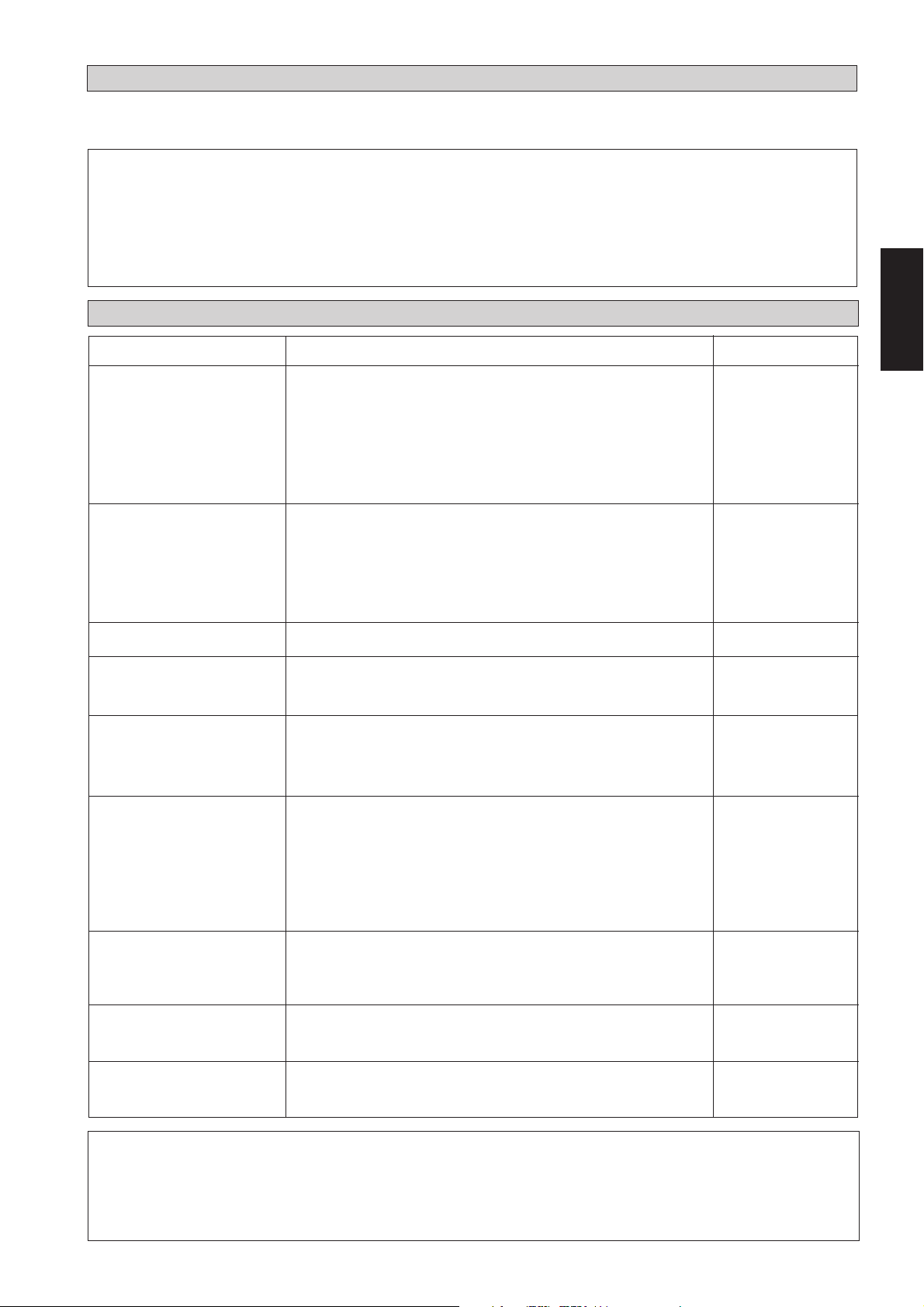
FONCTION DE REDEMARRAGE AU HASARD AUTOMATIQUE
En cas de coupure de courant lorsque l’unité est en marche, celle-ci redémarre selon le même mode d’opération une fois que
le courant est rétabli. (Applicable seulement pour les unités munies de cette fonction).
! Avertissement
Avant de débrancher l’unité, réglez l’interrupteur de la télécommande sur la position OFF afin d’éviter le déclenchement
inopportun de l’unité.
En cas d’oubli, le ventilateur se remet en marche automatiquement dès que le courant est rétable, ce qui peut constituer
un risque pour le personnel d’entretien ou pour les usagers.
ENTRETIEN ET MAINTENANCE
Pieces A Entretenir
Filtre à Air Intérieur
Unité Intérieure
Bac De Condensats
Ventilateur De L’unité
Intérieure
Batterie De L’unité
Intérieure Et Extérieure
Procédure D’Entretien
1. Enlever la poussière du filtre à l’aide d’un aspirateur ou en
lavant le filtre à l’eau tiède (moins de 40°C) avec un détergent
neutre.
2. Bien rincer et sécher le filtre avant de le remettre en place.
3. Ne pas utiliser de gasoil, de substances volatiles ou autres
produits chimiques pour nettoyer le filtre.
1. Nettoyer la grille et le panneau en les essuyant avec un chiffon doux mouillé à l’eau tiède (moins de 40°C) et un détergent
neutre.
2. Ne pas utiliser de gasoil, de substances volatiles ou autres
produits chimiques pour nettoyer l’unité intérieure.
1. Vérifier son état de propreté et nettoyer si nécessaire.
1. Vérifier l’absence de tout bruit anormal.
1. Vérifier et retirer toute saleté accumulée entre les ailettes.
2. Vérifier et retirer tout obstacle au flux d’air aspiré ou dégagé
des unités intérieure et extérieure.
Périodicité
Au moins une fois
toutes les 2
semaines.
Plus souvent si
nécessaire.
Au moins une fois
toutes les 2
semaines.
Plus souvent si
nécessaire.
Tous les 3 mois.
En cas de besoin.
Chaque mois.
Chaque mois.
Français
Alimentation Électrique
Compresseur
Huile De Compresseur
Huile De Moteur Du
Ventilateur
1. Vérifier la tension et l’alimentation électrique des unités
intérieur et extérieur.
2. Vérifier le câblage électrique pour détecter d’éventuels faux
contacts dus à des connexions mal assurées, des corps
étrangers, etc. En cas de besoin, resserrer les câbles sur le
connecteur.
1. Ne nécessite aucun entretien tant que le circuit réfrigérant reste
étanche. Vérifier cependant l’absence de fuites au niveau des
joints et raccords.
1. La charge en huile de compresseur est assurée en usine. Aucun
complément n’est nécessaire tant que le circuit reste étanche.
1. Tous les moteurs de ventilateurs sont prélubrifiés d'usine.
Tous les 2 mois.
Tous les 2 mois.
Tous les 6 mois.
Aucune maintenance
n'est nécessaire.
Aucune maintenance
! Avertissement
Ne pas utiliser d’appareil de chauffage à proximité du climatiseur. La chaleur excessive pourrait faire fondre ou
déformer le panneau en plastique.
2-13
Page 34

ANALYSE DES CAUSES DE DYSFONCTIONNEMENT
En cas de dysfonctionnement du climatiseur, couper aussitôt l’alimentation électrique. Vérifier ensuite les
points suivants pour détecter la nature et les causes de la panne.
Defauts
1. Le compresseur ne démarre pas 3 minutes après la
mise en marche du climatiseur.
2. Le climatiseur ne fonctionne pas.
3. Le flux d’air est trop faible.
4. L’affichage de la télécommande est de faible intensité.
5. L’air dégagé a une mauvaise odeur.
Causes
- Protection contre les démarrages fréquents. Laisser 3 à 4
minutes au compresseur pour démarrer.
- Le circuit est peut être coupé ou un fusible est à changer.
- La prise de courant est peut être débranchée.
- La programmation de mise en marche/arrêt est peut-être
mal réglée.
- Si la panne persiste après ces vérifications, contacter
l’installateur.
- Le filtre à air est sale.
- Les portes ou les fenêtres sont ouvertes.
- Les entrées et sorties d’air sont bouchées.
- La température réglée n’est pas assez élevée.
- Les piles sont épuisées.
- Les piles ne sont pas bien en place.
- Les odeurs peuvent provenir de fumées de cigarettes,
parfums ou autres particules adhérants au refroidisseur.
6. Condensation sur la grille frontale de l’unité intérieure.
7. Ecoulement d’eau du climatiseur.
8. Bruit de chuintement venant du climatiseur.
- La condensation est due à l’humidité de l’air après une
période de fonctionnement prolongée.
- La température affichée est trop basse; augmenter la
température et faire tourner l’appareil à vitesse de
ventilation élevée.
- Vérifier l'évacuatioon des condensats.
- Le fluide réfrigérant coule dans le serpentin de
l’évaporateur.
Si les pannes persistent, appeler votre revendeur ou le service après-vente.
2-14
Page 35

MONTAGEANLEITUNG
Das vorliegende Handbuch enthält die Installationsanweisungen für einen sicheren und ordnungsgemäßen
Betrieb dieser Anlage.
Je nach den örtlichen Gegebenheiten können spezielle Anpassungen notwendig sein.
Vor der Inbetriebnahme des Klimagerätes dieses Handbuch bitte aufmerksam zur Kenntnis nehmen und für
künftigen Bedarf aufbewahren.
ZWEITEILIGE KLIMAANLAGE FÜR VERKLEIDETE
DECKENMONTAGE
MODELL
KÜHLFUNKTION
CC10C / ACC10C
SL10B / ALC10B
SL10C / ALC10C
4SL10B / A4LC10B
5SL10C / A5LC10C
CC15C / ACC15C
SL15B / ALC15B
SL15C / ALC15C
4SL15B / A4LC15B
5SL15C / A5LC15C
CC20C / ACC20C
SL20B / ALC20B
4SL20B / A4LC20B
5SL20B / A5LC20B
CC25C / ACC25C
SL25B / ALC25B
4SL25B / A4LC25B
5SL25B / A5LC25B
CC28C / ACC28C
SL30B / ALC30B
SL30C / ALC30C
4SL30C / A4LC30C
5SL30C / A5LC30C
CC30C / ACC30C
SL30B / ALC30B
SL30C / ALC30C
4SL30C / A4LC30C
5SL30C / A5LC30C
CC38C / ACC38C
SL40C / ALC40C
4SL40C / A4LC40C
5SL40C / A5LC40C
CC40C / ACC40C
SL40C / ALC40C
4SL40C / A4LC40C
5SL40C / A5LC40C
CC50C / ACC50C
SL50C / ALC50C
4SL50C / A4LC50C
5SL50C / A5LC50C
CC60C / ACC60C
SL60C / ALC60C
4SL60C / A4LC60C
5SL60C / A5LC60C
MSS60C / AMC60C
WÄRMEPUMPE
CC10CR / ACC10CR
SL10BR / ALC10BR
SL10CR / ALC10CR
4SL10BR / A4LC10BR
5SL10CR / A5LC10CR
CC15CR / ACC15CR
SL15BR / ALC15BR
SL15CR / ALC15CR
4SL15BR / A4LC15BR
5SL15CR / A5LC15CR
CC20CR / ACC20CR
SL20BR / ALC20BR
4SL20BR / A4LC20BR
5SL20BR / A5LC20BR
CC25CR / ACC25CR
SL25BR / ALC25BR
4SL25BR / A4LC25BR
5SL25BR / A5LC25BR
CC28CR / ACC28CR
SL30BR / ALC30BR
SL30CR / ALC30CR
4SL30CR / A4LC30CR
5SL30CR / A5LC30CR
CC30CR / ACC30CR
SL30BR / ALC30BR
SL30CR / ALC30CR
4SL30CR / A4LC30CR
5SL30CR / A5LC30CR
CC38CR / ACC38CR
SL40CR / ALC40CR
4SL40CR / A4LC40CR
5SL40CR / A5LC40CR
CC40CR / ACC40CR
SL40CR / ALC40CR
4SL40CR / A4LC40CR
5SL40CR / A5LC40CR
CC50CR / ACC50CR
SL50CR / ALC50CR
4SL50CR / A4LC50CR
5SL50CR / A5LC50CR
CC60CR / ACC60CR
SL60CR / ALC60CR
4SL60CR / A4LC60CR
5SL60CR / A5LC60CR
MSS60CR / AMC60CR
Deutsch
Part No.: A08019025456
IM-CCC-0501(3)-Acson
3-1
Page 36

INHALT
- Auslegung und Ab-Messungen seite i – iv
- Sicherheits-Massnahmen seite 2
- Installationdiagramm seite 3
- Installation des Innenmontage-Gerätes seite 3
- Installation des Aussenanlage-Gerätes seite 4
- Kühlmittelleitung seite 4
- Kabelanschluss seite 5
- Spezielle Vorkehrungen Beim Beschäftigen R410A Maßeinheit seite 9
- Spezielle Vorkehrungen Beim Beschäftigen R407C Maßeinheit seite 9
- Reinigung der Kühlrohrleitung seite 9
- Gesamttest seite 10
- Besondere Vorsichtsmassnahmen Bei Der Na Chfüllung Von Copeland-scroll-verdichtern seite 11
- Komplettprufüng seite 12
- Standard-Betriebsbedingungen seite 12
- Automatische nicht-zeitgebundene Wiedereinschaltungsfunktion seite 13
- Instandhaltung und Wartung seite 13
- Störungs-Behebung seite 14
SICHERHEITS-MASSNAHMEN
Vor der Installation sind nachfolgende Sicherheitsmaßnahmen aufmerksam zur Kenntnis zu nehmen.
! Achtung
• Die Installation und Wartung muß durch qualifizietes Personal erfolgen, Welches mit den örtlichen Bestimmungen
und diesem Ausrüstungstyp vertraut ist.
• Die gesamte E-Verkabelung hat in Übereinstimmung mit den landesspezifischen Anschlußvorschriften zu erfolgen.
• Vor dem Kabelanschluß gemäß Schaltbild ist sicherzustellen, daß die Betriebsspannung mit der auf dem Datenschild
des Gerätes angegebenen Spannung übereinstimmt.
• Das Gerät ist zum Schutz gegen fehlerhafte Isolierungen und entsprechende Risiken zu ERDEN.
• Die Kabel dürfen weder mit der Kühlmittelleitung, noch mit dem Kompressor oder den beweglichen Teilen der
Gebläsemotoren in Berührung kommen.
• Vor der Installation oder Wartung der Anlage ist sicherzustellen, daß das Gerät ausgeschaltet ist (OFF).
WICHTIG
DAS KLIMAGERÄT SOLLTE NICHT IN EINEM WÄSCHERAUM INSTALLIERT
ODER BENUTZT WERDEN.
! Vorsicht
Vor der Installation sind folgende wichtige Punkte zu prüfen.
• Gerät nicht installieren, falls ein Leck entzündbaren Gases festgestellt wird.
Es besteht Feuergefahr, wenn Gas aus der Anlage entweicht und sich in der Umgebung ansammelt.
• Die Kondensat-Abflußleitung muß sachgemäß angeschlossen sein.
Ist die Abflußleitung nicht richtig angeschlossen, besteht Gefahr, daß durch auslaufendes Wasser
das Mobiliar feucht wird.
• Gerät nicht überlasten.
Das Gerät ist werkseitig vorgefüllt. Im Falle einer Überfüllung besteht die Gefahr einer Überbelastung
oder sonstigen Beschädigung des Kompressors.
• Nach Installation oder Wartung ist sicherzustellen, daß die Geräteabdeckung wieder montiert ist.
Eine mangelhafte Befestigung der Abdeckung führt zu Geräuschentwicklung während des Betriebs.
3-2
Page 37

Innen-Gerät
INSTALLATIONDIAGRAMM
Kältemittelleitung
Lufteinlass
Lufteinlass
Luftauslassdüse
INSTALLATION DES INNENMONTAGE-GERÄTES
Das Innenteil muss so installiert werden, dass der
Kühlluftauslaß nicht direkt zurückgesaugt werden kann.
Beachten Sie bei der Installation den erforderlichen Abstand.
Installieren Sie das Innenteil nicht an einem Ort mit direkter
Sonneneinstrahlung. Der Installationsort muss für die
Verlegung der Rohr- und Ablaufleitungen geeignet und
möglichst weit von Türen entfernt sein.
Verkleidete Deckenmontage
– Verwenden Sie die mit dem Gerät gelieferte Abhängung.
– Prüfen Sie, ob die Wand ausreichend stark für das Gewicht
ist.
Zentrieren Sie den Achsabstand (siehe untenstehende Zeichnung)
A
Deutsch
Aussen-Gerät
CC A mm (zoll) L mm (zoll)
10 C/CR 741 (29,2) 225 (8,9)
15 C/CR 881 (34,7) 225 (8,9)
20 C/CR 1041 (41,0) 225 (8,9)
25 C/CR 1176 (46,3) 225 (8,9)
28 C/CR 959 (37,8) 339 (13,3)
30 C/CR 956 (37,6) 266 (10,5)
38 C/CR 1264 (49,8) 401 (15,8)
40 C/CR 1076 (42,4) 266 (10,5)
50 C/CR 1326 (52,2) 266 (10,5)
60 C/CR 1526 (60,1) 266 (10,5)
Sorgen Sie entsprechend der Zeichnung für ausreichenden Abstand
zur Erleichterung von Wartungsarbeiten und für optimalen
Luftdurchsatz.
10 mm (32,8)
L
10 mm (32,8)
3-3
Page 38

INSTALLATION DES AUSSENANLAGE-GERÄTES
Das Außenteil muß so installiert werden, dass der Luftauslaß nicht
direkt zurückgesaugt oder blockiert werden kann.
der Installation angegebenen Abstand.
Wählen Sie möglichst den
kühlsten Ort, wo die angesaugte Luft nicht wärmer als die
Außentemperatur (maximal 45°C) ist.
Achten Sie darauf, dass der Luftstrom zum oder vom Gerät nicht
behindert wird. Entfernen Sie alle Hindernisse, die den Luftstrom zum
oder vom Gerät blockieren könnten.
Beachten Sie bei
Montageabstände des Aussengeräts SL-modellreihen
(zoll mm)
Der Installationsort muss gut belüftet sein, damit das Gerät ausreichend
Luft ansaugen, kühlen und zur Senkung der Raumtemperatur verteilen
kann.
Der Standort muß das Gewicht des Außengerätes tragen können und
sollte zugleich eine Geräusch- und Vibrationsisolierung bieten.
Der Standort sollte auch vor direkter Sonneneinstrahlung geschützt
sein. Ggf. ist ein Sonnenschutz anzubringen.
Der Standort darf nicht einer stark staub-, öl-, salz- oder
schwefelhaltigen Luft ausgesetzt sein.
KÜHLMITTELLEITUNG
300
Luftzufuhr
Wandelement
300 500
Luftzufuhr
Wandelement
1000
Auslassluft
Wandelement
Wandelement
Wartungs-Offnung
Hinweis: Falls der obere Teil des Gerätes durch über 2 m hohe
Bauelelemente oder sonstige Hindernisse beeinträchtigt
wird, ist der in der Tabelle angegebene Abstand größer
zu bemessen.
Maximale Rohrlänge und Anzahlan Bögen
Bei übermäßiger Rohrleitungslänge werden Leistung und
Zuverlässigkeit beeinträchtigt. Wenn die Rohrleitung zu viele
Leitungskrümmungen hat, muß das Kühlmittel höheren Widerstand
überwinden, wodurch die Kühlkapazität reduziert wird und der
Kompressor beschädigt werden kann. Wählen Sie stets den kürzesten
Weg, und beachten Sie die Empfehlungen in der untenstehenden
Tabelle.
Modell
Tabelle
Maximale Länge, A m (fuß)
Maximale Höhe, B m (fuß)
Maximale Bogenanzahl, C 10 10 10 10 10
Modell
Tabelle
Maximale Länge, A m (fuß)
Maximale Höhe, B m (fuß)
Maximale Bogenanzahl, C 10 10 10 10 8
Hinweis: Beim Kühlgerät CC60C wird empfohlen, einen
externen Sammler für 6kg hinzuzufügen.
10 15 20 25 28
12 12 15 15 35
(39,4) (39,4) (49,2) (49,2) (114,8)
558810
(16,4) (16,4) (26,2) (26,2) (32,8)
30 38 40 50 60
35 35 35 35 35
(114,8) (114,8) (114,8)(114,8) (114,8)
10 10 10 10 10
(32,8) (32,8) (32,8) (32,8) (32,8)
A
C
C
A
C
B
B
3-4
Page 39

Leitungsverlegung U. Anschlusstechnik
Keine verschmutzten oder beschädigten Kupferleitungen. Wenn jegliche
Rohrleitungen, der Verdampfer oder der Verdichter mehr als 15
Sekunden lang geöffnet geblieben sind, muss das System entleert
werden. Entfernen Sie grundsätzlich keine Kunststoff- oder
Gummistopfen und Messingmuttern von den Ventilen, Beschlägen,
Rohrleitungen und Kühlschlangen, solange die Verbindung hergestellt
ist.
Falls Lötarbeiten vorzunehmen sind, sicherstellen, daß Während des
Lötens Stickstoff durch die Wärmetauscher und Kupplungen gerührt
wird. Dadurch werden Rußablagerungen auf den KupferrohrInnenwandungen vermieden.
Rohrleitungen nach und nach zurechtschneiden und dabei das
Schneidegerät langsam in das Rohr eingreifen lassen. Höherer
Kraftaufwand und ein schneller Schnittvorschub verursachen eine
stärkere Verformung des Rohres und zusätzliche Gratstellen.
Rohrkanten mit einer Reibahle entgraten, wie in Abb. O dargestellt.
Dadurch werden Unregelmäßigkeiten an der Anschlußfläche
vermieden, die zu undichten Stellen führen könnten. Rohrende nach
unten halten, um das Eindringen von Metallpartikeln in das Rohr zu
vermeiden.
Die Gewindeüberwurfteile an den Armaturen des Innen-und
Außengerätes auf die Kupferrohre ziehen.
Die genaue überstehende Rohrleitungslänge an der KupplungsStirnfläche richtet sich nach dem Kupplungswerkzeug.
Das Rohr fest auf den Aufweitehals aufdrücken. Anschließend
Gewinde-und Überwurfteil zentrieren und beide Teile gegeneinander
festziehen.
Zuschneiden Des Kupferrohres
Geräte-Rohranschluss
Rohrleitung zentrieren und Gegenmutter des aufgeweiteten Rohrstückes
mit der Hand anziehen.
Abschließend Gewindemutter und Moment-schlüssel bis an die
gewünschte Moment-Einraststelle anziehen.
Beim Anziehen der Gewindemutter mit dem Momentschlüssel ist die
durch den Pfeil angezeigte Anzugsrichtung des Momentschlüssels zu
beachten.
Die Anschlüsse der Kühlrohrleitung müssen mit Polyurethan
(ARMAFLEX oder ähnlichem Material) isoliert werden.
Ø Rohr, D A (mm)
Zoll mm Aufgeweite Starr
1/4" 6,35 1,3 0,7
3/8" 9,52 1,6 1,0
1/2" 12,70 1,9 1,3
5/8" 15,88 2,2 1,7
3/4" 19,05 2,5 2,0
Rohrgröße, mm (zoll) Anzugsmoment (Nm)
6,35 (1/4) 18
9,53 (3/8) 42
12,7 (1/2) 55
15,88 (5/8) 65
19,05 (3/4) 78
Anzugsring
Aufgeweitetes Rohr
Deutsch
1/4t
Kupferrohr
Abb. R
Rohrentgratung
Kupferrohr
Stauchblock
Es ist sicherzustellen, daß die Adernfarbkennung des Außengerätes sowie die
! Vorsicht
Kühlen-Gerat, CC 10 / 15 / 20 / 25C
Klemmenkennungen jeweils mit denen des Innengerätes übereinstimmen.
KABELANSCHLUSS
Innenmontagerohr
Anzugsschlüssel
Gewinde-Überwurf
Drehmoment-Schlüssel
Innen-Gerät CC 10C CC 15C CC 20C CC 25C
Aussen-Gerät SL 10B SL 15B SL 20B SL 25B
Spannungsbereich**
220V – 240V /1Ph /50Hz + ! oder 208V–230V /1Ph /60Hz + !
Empfohlene Sicherung* A 10 10 16 20
Zuleitungskabelquerschnitt* mm
2
1,5 1,5 2,5 2,5
Adernanzahl 33 3 3
Zwischenkabelquerschnitt* mm
2
1,5 1,5 2,5 2,5
Adernanzahl 33 3 3
3-5
Page 40

CC 10 / 15 / 20 / 25 C - SL 10 / 15 / 20 / 25 B
CC 28 / 30 C - SL 30 B
COMP
L
COMP
N
Außen GerätKlemmenblock
!
Als Ein-/Ausschalter muß ein
Zweiphasenschalter mit mindestens
!
3 mm Abstand zwischen den
Schaltkontakten sowie eine
Sicherung bzw. ein Schaltschütz
gemäß den Empfehlunggen für die
Festinstallation verwendet werden.
Innen Gerät-
Klemmenblock
Kühlen-Gerat, CC 28 / 30 C
N
N
!
!
Anschluss-Kabel
Innen-Gerät CC 28 / 30C
Aussen-Gerät SL 30B SL 30C
Spannungsbereich** 220V–240V / 1Ph / 50Hz + ! oder 208V–230V / 1Ph / 60Hz + !
Empfohlene Sicherung* A 25 25
Zuleitungskabelquerschnitt* mm
2
4,0 4,0
Adernanzahl 33
Zwischenkabelquerschnitt* mm
2
2,5 2,5
Adernanzahl 34
CC 28 / 30 C - SL 30 C
L
N
!
S
R
COMP
L
N
!
Außen GerätKlemmenblock
Als Ein-/Ausschalter muß ein
!
Zweiphasenschalter mit mindestens
3 mm Abstand zwischen den
Schaltkontakten sowie eine
Sicherung bzw. ein Schaltschütz
gemäß den Empfehlunggen für die
Festinstallation verwendet werden.
Kühlen-Gerat, CC 38 / 40 / 50 / 60 C
Innen Gerät-
Klemmenblock
COMP
L
N
N
!
!
Anschluss-Kabel
Innen-Gerät CC 38 / 40C CC 50C CC 60C
Aussen-Gerät SL 40C SL 50C SL 60C
oder MSS 60C
Spannungsbereich**
380V– 415V /3Ph /50Hz +N + ! oder 208V–230V /3Ph /60Hz + N + !
Empfohlene Sicherung* (50/60Hz) A 10/20 16/25 16/25
Zuleitungskabelquerschnitt* (50/60Hz) mm
2
1,5/2,5 2,5/4,0 2,5/4,0
Adernanzahl 555
Zwischenkabelquerschnitt* (50/60Hz) mm
2
1,5/1,5 1,5/1,5 1,5/1,5
Adernanzahl 444
WICHTIG: * Die angegeben Werte sind lediglich Richtwerte. Sie sind zu überprüfen und ggf. den örtlichen und/
oderlandesspezifischen Vorschriften und Bestimmungen anzugleichen. Des weiteren sind sie abhängig
von der Installationsart und dem Adernquerschnitt.
** Der geeignete Spannungsbereich sollte den Etikettdaten auf der Einheit entnommen werden. ETL
verzeichnete Daten gelten nur für einen 60Hz Netzanschluss.
3-6
Page 41
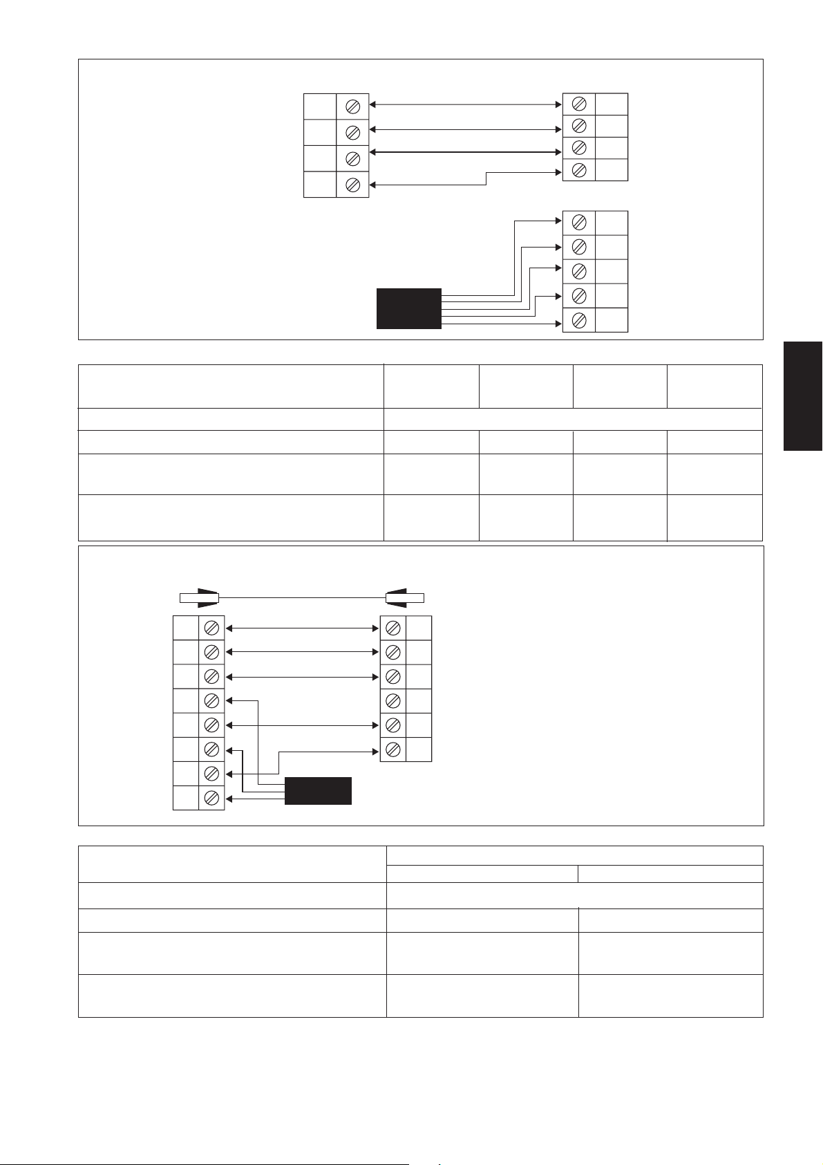
CC 38 / 40 / 50 / 60 C - SL 40 / 50 / 60 C
COMP
L
N
Innen Gerät-
Klemmenblock
COMP
L
N
!
Als Ein-/Ausschalter muß
!
ein Zweiphasenschalter mit
mindestens 3 mm Abstand
zwischen den Schaltkontakten
sowie eine Sicherung bzw. ein
Schaltschütz gemäß den
Empfehlunggen für die
Festinstallation verwendet
werden.
Wärmepumpe-Gerat, CC 10 / 15 / 20 / 25 CR
!
Anschluss-Kabel
Innen-Gerät CC 10CR CC 15CR CC 20CR CC 25CR
Aussen-Gerät SL 10BR SL 15BR SL 20BR SL 25BR
Spannungsbereich**
220V – 240V /1Ph /50Hz + ! oder 208V–230V /1Ph /60Hz + !
Empfohlene Sicherung* A 10 10 16 20
Zuleitungskabelquerschnitt* mm
2
1,5 1,5 2,5 2,5
Adernanzahl 33 3 3
Zwischenkabelquerschnitt* mm
2
1,5 1,5 2,5 2,5
Adernanzahl 55 5 5
Außen GerätKlemmenblock
R
S
T
N
!
Deutsch
CC 10 / 15 / 20 / 25 CR - SL 10 / 15 / 20 / 25 BR
Außenraum-Sensor
4WV
OF
Innen Gerät-
Klemmenblock
COMP
L
N
N
!
!
Wärmepumpe-Gerat, CC 28 / 30 CR
Anschluss-Kabel
4WV
OF
Außen Gerät-
COMP
Klemmenblock
N
!
Als Ein-/Ausschalter muß ein Zweiphasenschalter
!
mit mindestens 3 mm Abstand zwischen
den Schaltkontakten sowie eine Sicherung bzw.
ein Schaltschütz gemäß den Empfehlunggen für
die Festinstallation verwendet werden.
Innen-Gerät CC 28/30 CR
Aussen-Gerät SL 30BR SL 30CR
Spannungsbereich** 220V–240V /1Ph /50Hz + !
oder
208V–230V /1Ph /60Hz + !
Empfohlene Sicherung* A 25 25
Zuleitungskabelquerschnitt* mm
2
4,0 4,0
Adernanzahl 33
Zwischenkabelquerschnitt* mm
2
2,5 2,5
Adernanzahl 56
WICHTIG: * Die angegeben Werte sind lediglich Richtwerte. Sie sind zu überprüfen und ggf. den örtlichen und/
oderlandesspezifischen Vorschriften und Bestimmungen anzugleichen. Des weiteren sind sie abhängig von
der Installationsart und dem Adernquerschnitt.
** Der geeignete Spannungsbereich sollte den Etikettdaten auf der Einheit entnommen werden. ETL verzeichnete
Daten gelten nur für einen 60Hz Netzanschluss.
3-7
Page 42

CC 28 / 30 CR - SL 30 BR
Als Ein-/Ausschalter muß ein
!
Zweiphasenschalter mit mindestens
3 mm Abstand zwischen den
Schaltkontakten sowie eine Sicherung bzw.
ein Schaltschütz gemäß den Empfehlunggen
für die Festinstallation verwendet werden.
Innen Gerät-
Klemmenblock
A
4WV
OF
COMP
L
N
N
!
!
Außenraum-Sensor
4WV
OF
COMP
N
!
Anschluss-Kabel
Außen GerätKlemmenblock
CC 28 / 30 CR - SL 30 CR
Außenraum-Sensor
A
Innen Gerät-
Klemmenblock
Als Ein-/Ausschalter muß ein
!
Zweiphasenschalter mit mindestens
3 mm Abstand zwischen den
Schaltkontakten sowie eine Sicherung
bzw. ein Schaltschütz gemäß den
Empfehlunggen für die
Festinstallation verwendet werden.
Wärmepumpe-Gerat, CC 38 / 40 / 50 / 60 CR
Innen-Gerät
Aussen-Gerät
Spannungsbereich**
4WV
OF
COMP
L
N
N
!
!
Anschluss-Kabel
CC 38 / 40CR CC 50CR CC 60CR
SL 40CR SL 50CR
380V– 415V /3Ph /50Hz +N + ! oder 208V – 230V /3Ph /60Hz + N + !
A
4WV
OF
Außen Gerät-
COMP
Klemmenblock
L
N
!
L
N
!
SL 60CR oder MSS 60CR
Empfohlene Sicherung* (50/60Hz) A 10/20 16/25 16/25
Zuleitungskabelquerschnitt* (50/60Hz) mm
2
1,5/2,5 2,5/4,0 2,5/4,0
Adernanzahl 55 5
Zwischenkabelquerschnitt* (50/60Hz) mm
2
1,5/1,5 1,5/1,5 1,5/1,5
Adernanzahl 77 7
CC 38 / 40 / 50 / 60 CR - SL 40 / 50 / 60 CR
Als Ein-/Ausschalter muß ein
!
Zweiphasenschalter mit mindestens
3 mm Abstand zwischen den Schaltkontakten
sowie eine Sicherung bzw. ein Schaltschütz
gemäß den Empfehlunggen für die
Festinstallation verwendet werden.
WICHTIG: *
Die angegeben Werte sind lediglich Richtwerte. Sie sind zu überprüfen und ggf. den örtlichen und/oderlandesspezifischen
Vorschriften und Bestimmungen anzugleichen. Des weiteren sind sie abhängig von der Installationsart und dem Adernquerschnitt.
**
Der geeignete Spannungsbereich sollte den Etikettdaten auf der Einheit entnommen werden. ETL verzeichnete Daten gelten
nur für einen 60Hz Netzanschluss.
Innen Gerät-
Klemmenblock
A
4WV
OF
COMP
L
N
!
Anschluss-Kabel
3-8
Außenraum-Sensor
A
4WV
OF
COMP
L
N
!
R
S
T
N
!
Außen GerätKlemmenblock
Page 43

! Vorsicht
Es ist sicherzustellen, daß die Adernfarbkennung des Außengerätes sowie die Klemmenkennungen jeweils mit denen
des Innengerätes übereinstimmen.
SPEZIELLE VORKEHRUNGEN BEIM BESCHÄFTIGEN R410A MAßEINHEIT
R410A ist ein neues HFC Kühlmittel, das nicht die Ozon-Schicht
beschädigt. Der Funktion Druck dieses neuen Kühlmittels ist
1.ist 6mal stark als herkömmliches Kühlmittel (R22), so korrektes
installation/servicing wesentlich.
• Nie Kühlmittel des Gebrauches anders als R410A in einer
Klimaanlage, die entworfen ist, um mit R410A zu
funktionieren.
• POE Öl wird als Schmiermittel für R410A copressor benutzt,
das zu dem Mineralöl unterschiedlich ist, das für Kompressor
R22 benutzt wird. Während der Installation oder der Wartung
muß weitere Vorsichtsmaßnahme genommen werden, um das
R410A System auszusetzen, das nicht feuchter Luft zu lang
ist. Rest-POE Öl in der Rohrleitung und Bestandteile cn
saugen Feuchtigkeit von der Luft auf.
• Dem Aufflackernventil zu dem von R22 unterschiedlich.
• Benutzen Sie Werkzeuge und Materialien ausschließlich für
SPEZIELLE VORKEHRUNGEN BEIM BESCHÄFTIGEN R407C MAßEINHEIT
• R407C ist eine zeotropic abkühlende Mischung, die
nullozon-Entleerungpotential hat und folglich an die
Montreal Protokollregelung anpaßt. Es erfordert Öl des
Polyolester-Öls (POE) für Schmiermittel seines
Kompressors. Seine abkühlende Kapazität und Leistung sind
ungefähr das Gleiche wie das Kühlmittel R22.
• POE Öl wird als Schmiermittel für R407C Kompressor
benutzt, der zu dem Mineralöl unterschiedlich ist, das für
Kompressor R22 benutzt wird. Während der Installation oder
der Wartung muß weitere Vorsichtsmaßnahme genommen
werden, um das R407C System auszusetzen, das nicht
feuchter Luft zu lang ist. Rest-POE Öl in der Rohrleitung
und Bestandteile können Feuchtigkeit von der Luft
aufsaugen.
• Kühlmittel R407C wird leicht durch den Staub der
Feuchtigkeit verglichen mit R22, sicherstellen, die Enden
des Schläuche vor Installation vorübergehend zu umfassen
beeinflußt.
• Keine zusätzliche Aufladung des Kompressoröls wird die
Erlaubnis gehabt.
Kühlmittel R410A. Werkzeuge ausschließlich für R410A
sind vielfältiges Ventil, aufladenschlauch, Druckanzeiger,
GasleckstellDetektor, Aufflackernwerkzeuge,
Drehkraftschlüssel, Vakuumpumpe und Kühlmittelzylinder.
• Da eine R410A Klimaanlage auf höheren Druck als
Maßeinheiten R22 sich nimmt, ist es wesentlich, die kupfernen
Rohre richtig zu wählen. Nie kupferner Rohrverdünner des
Benutzers als 0,8mm obwohl sie im Markt vorhanden sind.
• Wenn das Kühlmittelgas während der Installation /servicing
ausläuft, seien Sie sicher, völlig zu lüften. Wenn das
abkühlende Gas in Kontakt mit Feuer kommt, kann ein giftiges
Gas auftreten.
• Wenn Sie eine Klimaanlage, lassen Sie Luft oder Feuchtigkeit
nicht im abkühlenden Zyklus bleiben anbringen oder
entfernen.
Deutsch
• Kein anderes Kühlmittel anders als R407C.
• Werkzeuge spezifisch für nur R407C (darf nicht für R22 oder
anderes Kühlmittel verwendet werden)
i) Vielfältige Lehre und aufladenschlauch
ii) Gasleckstelle Detektor
iii) Abkühlender cylinder/charging Zylinder
iv) Adapter der Vakuumpumpe c/w
v) Aufflackernwerkzeuge
vi) Abkühlende Wiederaufnahme Maschine
• Filter-Trockner muß entlang die flüssige Linie für alle R407C
Klimaanlagen angebracht werden. Dieses soll die
Verschmutzung der Feuchtigkeit und des Schmutzes im
abkühlenden System herabsetzen. Filter-Trockner muß von
der Molekularsiebart sein. Für ein Wärmepumpe System
bringen Sie einen Zweiwegflußfiltertrockner entlang der
flüssigen Linie an.
REINIGUNG DER KÜHLROHRLEITUNG
Entlüftung Der Leitung Und Des Innenmontage Gerätes
Mit der Ausnahme des Außenmontage-Gerätes, welches mit dem
Kältemittel vorbefüllt ist, müssen das Innenmontage-Gerät sowie die
Kältemittel-Anschlußleitungen entlüftet werden, da Feuchtigkeit im
Kühlkreis zu einer Funktionsstörung des Kompressors führen kann.
Das Außenteil ist mit zwei Dreiweg-Kühlanschlussventilen bestückt. Das
Einlassventil ist das größere der beiden Ventile, und das kleinere ist das
Flüssigkeitsventil. Beide Ventile sind mit Wartungsanschlussventilen für
den Anschluss an ein Manometer bestückt.
• Die Abdeckungen vom Ventil und dem Wartungsanschluß abnehmen.
• Den Lademesser von der Mitte aus an die Vakuumpumpe
anschliessen.
• Den Lademesser an die Wartungsöffnung des 3-Weg-Ventils
anschliessen.
• Starten Sie die Vakuumpumpe. Prüfen Sie, ob das Manometer einen
Verteilerunterdruck von 0,9 bar anzeigt. Die Zeit bis zum Erreichen
dieses Unterdrucks hängt von der Kapazität der jeweiligen Pumpe
ab, beträgt jedoch normalerweise eine halbe Stunde.
3-9
• Schließen Sie das Verteilerventil, und schalten Sie die Vakuumpumpe
ab.
• Öffnen Sie das Ansaug- und das Flüssigkeitsventil am Außenteil
durch Drehen der Innensechskantschraube gegen den Uhrzeigersinn
(mit 4 mm-Schlüssel).
• Die Klimaanlage ist nun betriebsbereit.
• Wenn der Unterdruck nahe Null liegt, muss das Gerät (mit der
Vakuumpumpe) entleert und erneut mit Kühlmittel befüllt werden.
WartungsaNschluss
GewindeÜberwurf
Aussengerät-3Wege-Ventil
KältemittelLeitung
Flexible
Schlauchleitung
4 mm
Inbusschlissel
Page 44

Aussenanlage
Kältemittel-Leitung
Flüssigkeitsventil
Untererdruckseitiges
Gasventil
Manometer
Verteiler
GESAMTTEST
Das Außenmontage-Gerät ist bereits werkseitig mit Kältemittel befüllt.
Falls die Rohrleitung unter 5 m Länge aufweist, ist eine zusätzliche
Kältemittelbefüllung nach der Herstellung desVakuums nicht
erforderlich. Wenn die Rohrleitung länger als 5 m ist, sollte ein
zusätzliches Speiseventil gemäß den Angaben in der untenstehenden
Tabelle verwendet werden.
Kältemittel-Zusatzbefüllung
Dieser Arbeitsgang erfordert unbedingt den Einsatzeines GasFüllzylinders sowie einer Präzisionswaage. Die Zusatzbefüllung erfolgt
am Außenmontage-Gerät mithilfe des Ansaugventils und dem
Wartungsanschluß.
• Abdeckung der Wartungsöffnung entfernen.
• Verbinden Sie den Unterdruckverteiler mit dem Ansauganschluss,
zentrieren Sie den Verteiler auf dem Zylinderbehälter, und schließen
Sie den Überdruckverteiler (siehe untenstehende Abbildung).
Lassen Sie alles Kühlmittelgas aus der Schlauchleitung ab.
• Klimaanlage einschalten.
• Den Gaszylinder und das Niederdruck-Ladeventil öffnen.
• Sobald die benötigte Kältemittelmenge in das Gerät eingepumpt ist,
werden die Niederdrucköffnung des Lademessers und der
Gaszylinder geschlossen.
• Den Zulieferschlauch vom Gaszylinder entfernen und dieZylinderAbdeckung wieder anbringen.
Zusatzfüllung in Gramm (Kühleinheit)
Modell 7 m 10 m 15 m 20 m
CC 10C 27 67 – –
CC 15C 27 67 – –
CC 20C 27 67 135 –
CC 25C 68 171 342 –
CC 28C / CC 30C 90 225 450 675
CC 38C / CC 40C 90 225 450 675
CC 50C 90 225 450 675
CC 60C 90 225 450 675
(R410A)
Innen-Gerät
Hochdruck-Manometer
Flexible Schlauchleitung
Vakuum-Pumpe
Zusatzfüllung in Gramm (Wärmepumpen-Einheit)
(R410A)
Modell 7 m 10 m 15 m 20 m
CC 10CR 36 90 – –
CC 15CR 36 90 – –
CC 20CR 45 112 225 –
CC 25CR 90 225 450 –
CC 28CR / CC 30CR 90 225 450 675
CC 38CR / CC 40CR 90 225 450 675
CC 50CR 90 225 450 675
CC 60CR 90 225 450 675
Zusatzfüllung in Gramm (Kühleinheit)
(R22/R407C)
Modell 7 m 10 m 15 m 20 m
CC 10C 30 75 – –
CC 15C 30 75 – –
CC 20C 30 75 150 –
CC 25C 76 190 380 –
CC 28C / CC 30C 100 250 500 750
CC 38C / CC 40C 100 250 500 750
CC 50C 100 250 500 750
CC 60C 100 250 500 750
Zusatzfüllung in Gramm (Wärmepumpen-Einheit)
(R22/R407C)
Modell 7 m 10 m 15 m 20 m
CC 10CR 40 100 – –
CC 15CR 40 100 – –
CC 20CR 50 125 250 –
CC 25CR 100 250 500 –
CC 28CR / CC 30CR 100 250 500 750
CC 38CR / CC 40CR 100 250 500 750
CC 50CR 100 250 500 750
CC 60CR 100 250 500 750
3-10
Page 45

Überprüfung auf Kühlmittelaustritt
Prüfen mit einem Kühlmitteldetektor, ob am Ausdehnungsanschluss des Innen- und des Außenteils Kühlmittel austritt.
Tipp: Wenn nach einiger Betriebsdauer Ölspuren erkennbar sind, deutet dies auf eine undichte Stelle hin.
Aussenanlage
Flüssigkeitsventil
Gasventil
Kältemittel-Leitung
Untererdruckseitiges
Manometer
Verteiler
Flexible Schlauchleitung
Innen-Gerät
Hochdruck-Manometer
Kühlgasbehälter
BESONDERE VORSICHTSMASSNAHMEN BEI DER NACHFÜLLUNG VON
COPELAND-SCROLL-VERDICHTERN
Diese Vorsichtsmaßnahmen sind nur bei der Nachfüllung von Copeland-Scroll-Verdichtern mit den Kühlmitteln R22, R407C, R134A,
R404A, R507 und R410A anzuwenden. Sie finden keine Anwendung bei Hubkolbenverdichtern von Copeland oder Scroll-Verdichtern
anderer Hersteller.
Scroll-Verdichter haben einen sehr hohen volumetrischen Wirkungsgrad und erzeugen schnell eine Evakuierung, wenn sich im
System nicht genügend Kühlmittel befindet oder wenn das Kühlmittel zu langsam zugefügt wird. Betrieb mit einem niedrigen
Saugdruck wird schnell zu sehr hohen Druckrohrtemperaturen führen. Während dies erfolgt, werden die Spiralgehäuse nicht ausreichend
geschmiert – die Spiralgehäuse sind auf die Schmierwirkung des Ölnebels im Kühlmittel angewisen. Mangelnde Ölung führt zu
einer starken Reibung zwischen den Spiralgehäuseflanken und -düsen und erzeugt zusätzliche Wärme. Die Kombination aus
Verdichtungsswärme und Reibungswärme konzentriert sich in einer kleinen lokalisierten Ablasszone, wo die Temperatur schnell
300°C überschreiten kann. Durch diese extremen Temperaturen werden die Spiralen und die sie umgebenden Lager beschädigt.
Dieser Schaden kann, besonders bei großen Verdichtern, innerhalb von weniger als einer Minute auftreten. Der Betrieb kann schon
innerhalb weniger Stunden danach ausfallen oder der während der Ladung erfolgte Schaden tritt einige Zeit später auf.
Andere typische Probleme, die bei der Nachfüllung auftreten können, sind eine Unterfüllung, eine Überfüllung, Feuchtigkeit oder
Luft im System, etc. Jedes dieser Probleme kann ein Ausfallen des Verdichters verursachen.
Zur Nachfüllung vor Ort ist eine Mindestausrüstung erforderlich. Die Mindestausrüstung zur Ausführung dieser Tätigkeit besteht
aus:-
Einem Satz Betriebsmanometer Ein Vakuummeter
Schläuchen Eine Waage
Eine Vakuumpumpe Ein Thermometer
Bei der Nachfüllung von Kühlmittel sollten die Empfehlungen des Herstellers bezüglich des nachzufüllenden Volumens beachtet
werden.
1. Nachfüllungsverfahren – Einphasige Verdichter
Evakuieren Sie das System auf 500 Mikrometer Hg (67Pa). Benutzen Sie kurze Schläuche mit einem großen Durchmesser und
verbinden Sie diese mit unbeschränkten Auslassanschlüssen am System, um die Evakuationszeit zu reduzieren. Die Qualität des
Vakuums kann nicht der Zeit nach bestimmt werden – es muss ein zuverlässiges Vakuummeter (z.B. ein elektronisches
Vakuummeter) benutzt werden.
Stellen Sie den Kühlmitteltank auf den Kopf, setzen Sie den Nachfüllungsschlauch an und füllen Sie über den
Nachfüllungsanschluss der Flüssigkeitsleitung Kühlmittel ein, bis keines mehr hineinläuft oder bis die richtige Nachfüllungsmenge
abgewogen wurde. Sollte eine weitere Nachfüllung notwendig sein, setzen Sie das System in Betrieb und gießen Sie langsam
Flüssigkeit in die Saugseite, bis das System voll ist.
Copeland empfehlt eine KONTROLLIERTE Nachfüllung von Flüssigkeit in die Saugseite, bis das System voll ist. Diese
Empfehlung findet keine Anwendung bei Hubkolbenverdichtern, bei denen eine Nachfüllung von Flüssigkeit in die Saugseite
schwere Schäden verursachen kann.
Überwachen Sie aufmerksam den Saug- und den Verdichtungsdruck. Stellen Sie sicher, dass der Saugdruck zu keinem Zeitpunkt
während des Nachfüllungsverfahrens unter 25 psig (1,7 bar) fällt.
Deutsch
3-11
Page 46

! Vorsicht
• Das Mehrfachmessgerät wird eher den Druck im Tank als den Saugdruck anzeigen, wenn sowohl der Tankventil wie
der Ventil „A“ am Messgerät offen ist.
As gibt viele Wege, um Flüssigkeit auf „eine kontrollierte Art und Weise“ in die Saugseite
nachzufüllen:-
1. Benutzen Sie den Ventil A am Mehrfachmessgerätsatz
2. Benutzen Sie den Ventil auf dem Kühlmitteltank
3. Füllen Sie Kühlmittel über einen Schraderventil nach
4. Benutzen Sie einen Schlauch mit einem Schraderventildepressor
5. Füllen Sie Kühlmittel in die Saugseite unter Einhaltung eines Abstands zum
A
2. Nachfüllungsverfahren – Dreiphasige Verdichter
Das grundlegende Verfahren ist das gleiche wie bei einphasigen Modellen, aber hier kann der Verdichter bei der Inbetriebnahme
in die falsche Richtung starten. Sollte dies vorkommen, wechseln Sie zwei beliebige Phasen aus und setzten Sie den Verdichter
erneut in Betrieb.
Alle Specter-Verdichter (Modell: ZR90 bis ZR19M) von verfügen über interne Schutzmodule gegen überhöhte
Druckrohrtemperaturen, die sehr effektiv solche Temperaturen beim Nachfüllungsvorgang vorbeugen. Das Schutzmodul schaltet
sich in diesem Fall ein und setzt die Verdichter für 30 Minuten außer Betrieb. Es ist normalerweise nicht erforderlich, die 30
Minuten bis zur Rückstellung des Moduls abzuwarten. Wenn sich der Verdichter abgekühlt hat, kann das Modul zurückgestellt
werden, indem die Stromversorgung des Sicherungsstromkreises unterbrochen wird. Sehr oft versteht der Wartungsmonteur
nicht, warum sich das Modul eingeschaltet hat und benutzt ein Überbrückungskabel, um es zu umgehen. Er füllt das System
weiterhin auf und entfernt das Überbrückungskabel, wenn die Nachfüllung abgeschlossen ist. Auch wenn der Verdichter
funktioniert, wenn das Schutzmodul erneut in den Stromkreis gesetzt wird, ist es sicher, dass der Verdichter beschädigt wurde
und vorzeitiger ausfallen wird.
Verdichter ein
6. Alles, was oben aufgeführt wird
KOMPLETTPRÜFUNG
Folgendes ist sicherzustellen, insbesondere:-
1) Gerät muß fest und starr positioniert sein.
2) Nach dem Befüllen dürfen die Leitungen und Anschlüsse
kein Leck aufweisen.
3) Auf korrekte Verkabelung achten.
Drainage Text:- Etwas Wasser in die linke Seite der DrainageWanne ablassen (die Drainage erfolgt über die rechte
Geräteseite).
• Testlauf:
1) Nach dem Wasserablauftest und dem Überprüfen der
Anlage auf undichte Stellen ist ein Testlauf
durchzuführen.
STANDARD-BETRIEBSBEDINGUNG
Kühleinheit
Temperatur Ts °C / °F Th °C / °F
Mindest-
Innentemperatur
Maximale
Innentemperatur
Mindest-
Außentemperatur
Maximale
Außentemperatur
19,4 / 66,9 13,9 / 57,0
26,7 / 80,1 19,4 / 66,9
19,4 / 66,9 13,9 / 57,0
46 / 114,8 24 / 75,2
2) Auf Folgendes achten:a) Sitzt der Elektrostecker fest in der Steckdose?
b) Treten ungewöhnliche Geräusche am Gerät auf?
c) Läuft das Wasser unbehindert ab?
• Prüfen:
1) Ob Ventilator des Kondensators läuft, und das
Kondensatorgerät bläst Warmluft aus.
2) Ob as Verdunstergebläse läuft und Kaltluft abgibt.
3) Die Fernsteuerung aktiviert den Schaltkreis mit drei Minuten
Verzögerung, weshalb das Außengerät erst nach dieser
Zeitspanne zu arbeiten beginnt.
Wärmepumpe
Temperatur Ts °C / °F Th °C / °F
Mindest-
Innentemperatur
Maximale
Innentemperatur
Mindest-
Außentemperatur
Maximale
Außentemperatur
10 / 50 –
26,7 / 80,1 –
8 / 17,6 -9 / 15,8
24 / 75,2 18 / 64,4
Ts: Trockenkugel-Temperatur. Th: Feuchtkugeltemperatur.
! Achtung
• Vor Wartung des Klimagerätes das Stromkabel vom Netz trennen.
• Das Stromkabel nicht herausziehen, wenn das Gerät noch eingeschaltet ist. Ein elektrischer Schlag oder ein
Wohnungsbrand können die Folge sein.
3-12
Page 47
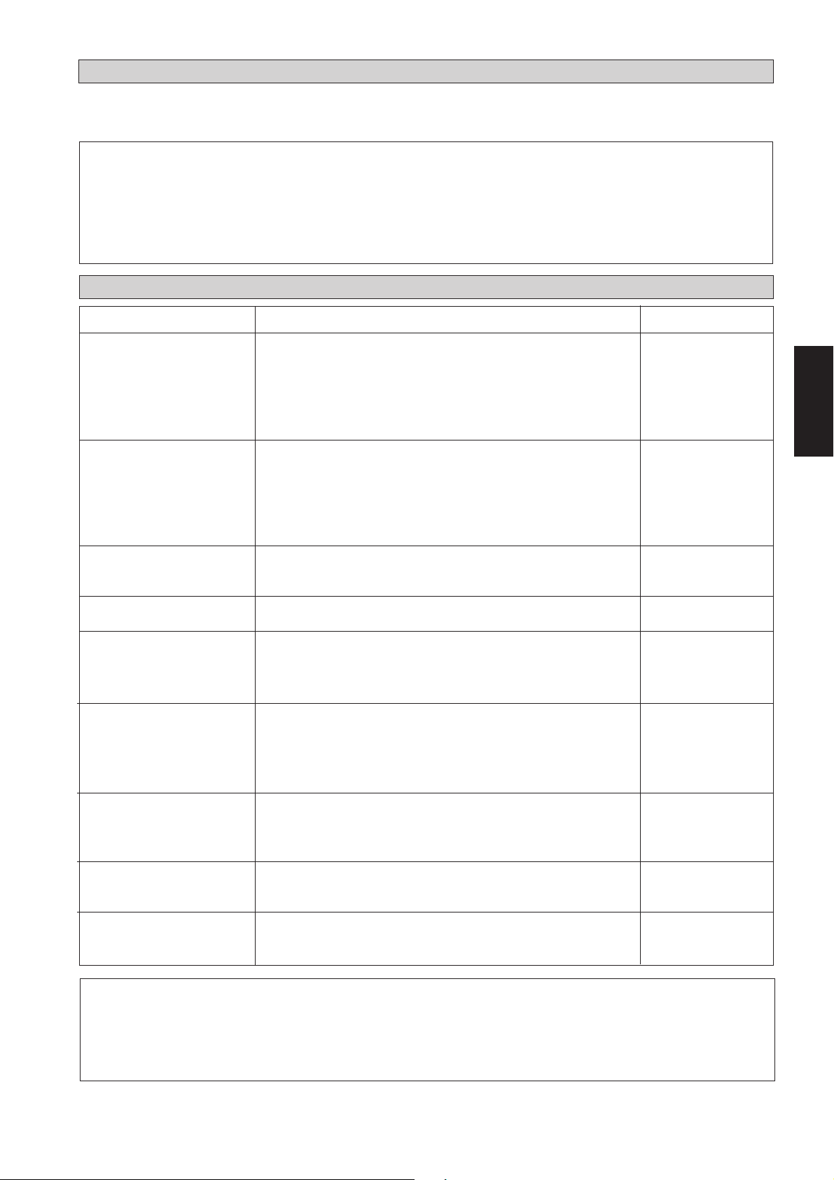
AUTOMATISCHE NICHT-ZEITGEBUNDENE WIEDEREINSCHALTUNGSFUNKTION
Sollte es zu einem Stromausfall kommen, wenn das Gerät in Betrieb ist, dann läuft das Gerät nach Wiederherstellung der
Stromversorgung automatisch in der gleichen Betriebsart weiter. (Gilt nur für hier aufgelistete Geräte).
! Vorsicht
Vor Abschalten der Stromzufuhr muss der EIN/AUS-Schalter der Fernbedienung auf “AUS” gestellt werden, um eine
versehentliche Fehleinstellung zu vermeiden.
Andernafalls schaltet sich bei Wiederherstellung der Stromzufuhr das Kühlgebläse automatisch wieder ein und kann
somit für den Benutzer oder Wartungspersonal ein unerwartetes Risiko darstellen.
INSTANDHALTUNG UND WARTUNG
Wartungsteile
Luftfilter Innengerät
Innen-Gerät
Kondensator-Wanne &
Leitung
Innen-Ventilator
Innen-/AußenWärmetauscher
Stromversorgung
Wartungsverfahren
1. Luftfilter mit Staubsauger absaugen oder in lauwarmem
Wasser (unter 40°C) mit neutraler Seife auswaschen.
2. Sorgfältig ausspülen und vor dem Wiedereinsetzen trocknen.
3. Weder Benzin, noch Verdünner oder sonstige Chemikalien zum
Reinigen verwenden.
1. Staub oder Schmutz an Gitter und Abdeckung mit einem
weichen Tuch abwischen. Das Tuch vorher in lauwarmem
Wasser (unter 40°C) mit neutraler Seife anfeuchten.
2. Weder Benzin, noch Verdünner oder sonstige Chemikalien zum
Reinigen verwenden.
1. Auf Sauberkeit überprüfen und ggf. reinigen.
1. Auf ungewöhnliche Geräuschentwicklung überprüfen.
1. Prüfen und ggf. Schmutz zwischen den Kühlrippen entfernen.
2. Prüfen und ggf. Gegenstände entfernen, die den Luftstrom in
und aus dem Innen- bzw. Außengerät behindern könnten.
1. Spannung und Stromwert am Innen- und Außengerät prüfen.
2. Verkabelung auf Fehlkontakte infolge gelöster Verbindungen,
Fremdkörper, usw. überprüfen. Ggf. die Kabel an den
Klemmen nachziehen.
Intervall
Mindestens alle 2
Wochen.
Ggf. häufiger.
Deutsch
Mindestens alle 2
Wochen.
Ggf. häufiger.
Alle drei Monate.
Falls notwendig.
Monatlich.
Monatlich.
Alle 2 Monate.
Alle 2 Monate.
Kompressor
Kompressor-Öl
Gebläsemotor-Öl
1. Keine Wartung erforderlich, soweit der Kältemittelkreis dicht
bleibt. Jedoch alle Anschlüsse und Armaturen auf undichte
Stellen überprüfen.
1. Der Kompressor ist werkseitig mit Öl befüllt. Soweit er dicht
bleibt, braucht kein Öl nachgefüllt zu werden.
1. Alle motoren sind werkseiting lebensdauergeschmiert und
gekapselt.
Alle 6 Monate.
Wartungsfrei.
Wartungsfrei.
! Vorsicht
Keine Heizgeräte in der Nähe der Klimaanlage einschalten, sonst kann die Kunststoffabdeckung durch zu grosse
Wärme schmelzen oder beschädigt werden.
3-13
Page 48

STÖRUNGS-BEHEBUNG
Im Falle einer Funktionsstörung ist das Gerät sofort auszuschalten. Nachfolgend einige Hinweise zur
Behebung von einfachen Störungen.
Störung
1. Der Kompressor setzt sich 3 Minuten nach Einschalten
des Klimagerätes nicht in Gang.
2. Das Klimagerät funktioniert nicht.
3. Der Luftstrom ist zu schwach.
4. Das Fernbedienungs-Display ist zu schwach.
5. Die ausgeblasene Luft riecht unangenehm.
Ursache
- Schutzeinrichtung gegen häufiges Anlassen. 3 bis 4
Minuten warten, bevor der Kompressor anläuft.
- Stromversorgung fehlerhaft/ggf. Sicherung austaushen.
- Netzstecker nicht eingesteckt.
- Timer möglicherweise falsch programmiert.
- Falls die Störung nach diesen Kontrollen weiterhin
besteht sollte der Installateur benachrichtigt werden.
- Luftfilter verschmutzt.
- Türen order Fenster geöffnet.
- Lufteinlaß bzw. Luftauslaß verstopft.
- Regeltemperatur nicht hoch genug.
- Batterien zu schwach.
- Batterien falsch eingesetzt.
- Geruchsbildung möglicherweise durch Zigarettenrauch,
Parfüm usw. und entsprechenden Ablagerungen am
Wärmetauscher.
6. Kondensation am Vordergitter des Innengerätes.
7. Wasser fließt aus dem Klimagerät.
8. Zischendes Geräusch während des Betriebs.
- Bedingt durch Luftfeuchtigkeit nach längerem Betrieb des
Gerätes.
- Eingestellte Temperatur zu niedrig; Temperatureinstellung
erhöhen und das Gerät bei hoher Gebläsedrehzahl laufen
lassen.
- Kondensatableitung prüfen.
- Kälteflüssigkeit tritt in den Verdunster ein.
Kann die Störung nicht behoben werden, sollte der örtliche Kundendienst bzw. der Installateur
benachrichtigt werden.
3-14
Page 49

MANUALE D’INSTALLAZIONE
Il presente manuale descrive come procedere all’installazione del condizionatore per assicurarne il corretto
funzionamento in condizioni di sicurezza.
Degli adattamenti possono rivelarsi necessari per rispondere a particolari esigenze locali.
Prima di utilizzare il condizionatore, leggere attentamente le presenti istruzioni. Conservarle per ogni evenienza
futura.
APPARECCHIO DI ARIA CONDIZIONATA TIPO DOPPIO
INSERITO NEL SOFFITTO
MODELLO
RAFFREDDAMENTO
CC10C / ACC10C
SL10B / ALC10B
SL10C / ALC10C
4SL10B / A4LC10B
5SL10C / A5LC10C
CC15C / ACC15C
SL15B / ALC15B
SL15C / ALC15C
4SL15B / A4LC15B
5SL15C / A5LC15C
CC20C / ACC20C
SL20B / ALC20B
4SL20B / A4LC20B
5SL20B / A5LC20B
CC25C / ACC25C
SL25B / ALC25B
4SL25B / A4LC25B
5SL25B / A5LC25B
CC28C / ACC28C
SL30B / ALC30B
SL30C / ALC30C
4SL30C / A4LC30C
5SL30C / A5LC30C
CC30C / ACC30C
SL30B / ALC30B
SL30C / ALC30C
4SL30C / A4LC30C
5SL30C / A5LC30C
CC38C / ACC38C
SL40C / ALC40C
4SL40C / A4LC40C
5SL40C / A5LC40C
CC40C / ACC40C
SL40C / ALC40C
4SL40C / A4LC40C
5SL40C / A5LC40C
CC50C / ACC50C
SL50C / ALC50C
4SL50C / A4LC50C
5SL50C / A5LC50C
CC60C / ACC60C
SL60C / ALC60C
4SL60C / A4LC60C
5SL60C / A5LC60C
MSS60C / AMC60C
RISCALDAMENTO
CC10CR / ACC10CR
SL10BR / ALC10BR
SL10CR / ALC10CR
4SL10BR / A4LC10BR
5SL10CR / A5LC10CR
CC15CR / ACC15CR
SL15BR / ALC15BR
SL15CR / ALC15CR
4SL15BR / A4LC15BR
5SL15CR / A5LC15CR
CC20CR / ACC20CR
SL20BR / ALC20BR
4SL20BR / A4LC20BR
5SL20BR / A5LC20BR
CC25CR / ACC25CR
SL25BR / ALC25BR
4SL25BR / A4LC25BR
5SL25BR / A5LC25BR
CC28CR / ACC28CR
SL30BR / ALC30BR
SL30CR / ALC30CR
4SL30CR / A4LC30CR
5SL30CR / A5LC30CR
CC30CR / ACC30CR
SL30BR / ALC30BR
SL30CR / ALC30CR
4SL30CR / A4LC30CR
5SL30CR / A5LC30CR
CC38CR / ACC38CR
SL40CR / ALC40CR
4SL40CR / A4LC40CR
5SL40CR / A5LC40CR
CC40CR / ACC40CR
SL40CR / ALC40CR
4SL40CR / A4LC40CR
5SL40CR / A5LC40CR
CC50CR / ACC50CR
SL50CR / ALC50CR
4SL50CR / A4LC50CR
5SL50CR / A5LC50CR
CC60CR / ACC60CR
SL60CR / ALC60CR
4SL60CR / A4LC60CR
5SL60CR / A5LC60CR
MSS60CR / AMC60CR
Italiano
Part No.: A08019025456
IM-CCC-0501(3)-Acson
4-1
Page 50

SOMMARIO
- Disegni e Dimensioni pag. i-iv
- Norme di Sicurezza pag. 2
- Diagramma per L’Installazione pag. 3
- Installazione dell’unità interna pag. 3
- Installazione dell’unità esterna pag. 4
- Condotti del refrigerante pag. 4
- Allacciamenti Elettrici pag. 5
- Precauzioni Speciali Quando Si Occupano Dell'Unità di R410A pag. 9
- Precauzioni Speciali Quando Si Occupano Dell'Unità di R407C pag. 9
- Purga dei Tubi di Refrigerante pag. 9
- Ricarica Addizionale pag. 10
- Precauzioni Speciali per la Carica dell'apparecchio con Compressori a Spirale Orbitante (Scroll) Copeland pag. 11
- Controlli Generali pag. 12
- Condizioni di Funzionamento Standard pag. 12
- Funzione di Ri-accensione Casuale Automatica pag. 13
- Pulizia e Manutenzione pag. 13
- Guasti e Riparazioni pag. 14
NORME DI SICUREZZA
Leggere attentamente le norme di sicurezza che seguono, prima di procedere all’installazione.
! Avvertenza
• L’installazione e la manutenzione devono essere eseguite da personale qualificato, competente in questo genere di
apparecchi e al corrente delle leggi e regolamenti in vigore.
• Tutti gli allacciamenti elettrici devono essere eseguiti conformemente alla regolamentazione elettrica in vigore.
• Prima di procedere agli allacciamenti secondo lo schema elettrico presentato più avanti, accertarsi che il voltaggio
dell’apparecchio corrisponda a quello della rete.
• Dotare il condizionatore di una presa di TERRA al fine di prevenire i rischi originati da eventuali deficienze del
sistema di isolamento.
• Evitare chi i fili elettrici tocchino condotti del refrigerante, il compressore o un qualsiasi organo rotante dei motori
della ventola.
• Prima di installare il condizionatore o di procedere ad interventi di manutenzione, accertarsi che sia spento (OFF).
IMPORTANTE
IL CONDIZIONATORE NON DEVE MAI ESSERE INSTALLATO O USATO IN UNA LAVANDERIA.
! Cautela
Durante l’installazione, verificare accuratamente i punti seguenti.
• Non procedere all’installazione in luoghi dove possano verificarsi fughe di gas.
Pericolo d’incendio in caso di fughe o di concentrazioni di gas intorno al condizionatore.
• Verificare che i condotti di drenaggio siano stati correttamente installati.
Un’installazione incorretta può causare delle perdite d’acqua e danneggiare il mobilio.
• Non sovraccaricare il condizionatore.
L’apparecchio è precaricato in fabbrica. Qualsiasi sovraccarico provoca una sovracorrente e può
danneggiare il compressore.
•
Dopo l’installazione o gli interventi di manutenzione accertarsi di rimettere a posto il pannello di chiusura.
Una difettosa chiusura del pannello è causa di rumori durante il funzionamento.
4-2
Page 51

Unità Interna
Ingresso Dell’Aria
Effusore Della Ventola
Di Aerazione
DIAGRAMMA PER L’INSTALLAZIONE
Ingresso Dell’Aria
Condotti Del
Refrigerante
INSTALLAZIONE DELL’ UNITÀ INTERNA
L’unità interna deve essere installata di modo a evitare
cortocircuiti nella scarica fredda. All’installazione lasciare
le distanze previste. Non montare l’unità interna in posizione
sposta alla luce solare diretta. La posizione deve essere
adeguata per i tubi e la scarica deve prevedere una ampia
distanza tra la porta e l’unità.
Montaggio Inserito Nel Soffitto
– Usare il gancio fornito in corredo all’unità.
– Certificarsi che la parete è abbastanza forte da sopportare
il peso.
Distanza centrale dall’asse (vedere seguente disegno).
A
Italiano
Unità Esterna
CC A mm (pollici) L mm (pollici)
10 C/CR 741 (29,2) 225 (8,9)
15 C/CR 881 (34,7) 225 (8,9)
20 C/CR 1041 (41,0) 225 (8,9)
25 C/CR 1176 (46,3) 225 (8,9)
28 C/CR 959 (37,8) 339 (13,3)
30 C/CR 956 (37,6) 266 (10,5)
38 C/CR 1264 (49,8) 401 (15,8)
40 C/CR 1076 (42,4) 266 (10,5)
50 C/CR 1326 (52,2) 266 (10,5)
60 C/CR 1526 (60,1) 266 (10,5)
Prevedere spazi per facile assistenza tecnica e per un flusso
d'aria ottimale, come presentato nel diagramma.
10 mm (32,8)
L
10 mm (32,8)
4-3
Page 52

INSTALLAZIONE DELL’UNITÀ ESTERNA
L’unità esterna deve essere installata di modo da evitare cortocircuiti
dell’aria della scarica d’aria e ostacoli ad un libero flusso dell’aria.
Nell’installazione, osservare la distanza. Selezionare il luogo più
freddo possibile per le prese d’aria, comunque ad una temperatura
non superiore di quella esterna (max. 45°C).
Assicurarsi che non ci siano ostacoli al flusso d’aria verso e dalla
unità. Eliminare gli eventuali ostacoli che ostruiscono la presa e la
scarica d’aria.
Distanze di sicurezza per l’installazione dell’unità esterna
modelli SL (in mm)
300
Aria Di Ritorno
Ostacolo
300 500
1000
Uscita
Dell’Aria
Ostacolo
Il locale deve essere ben ventilato, di modo che l'unità possa capitare e distribuire molta aria per abbassarne la temperatura.
Assicurarsi che il luogo prescelto per l’installazione dell’unità
esterna sia in grado di sopportarne il peso e di assicurare una buona
isolazione contro il rumore e le vibrazioni.
Assicurarsi che il luogo prescelto non sia direttamente esposto ai
raggi del sole. Utilizzare una tenda di protezione se necessario.
Evitare di scegliere un luogo soggetto ad alte concentrazioni di
polvere, sali o gas sulfurei.
CONDOTTI DEL REFRIGERANTE
Lunghezza Massima Dei Condotti E Massimo
Numero Di Gomiti
Nel caso di lunghezza eccessive dei tubi, sia la capacità sia
l’affidabilità diminuiranno. Nel caso di aumento di numero di curve,
la resistenza dei tubi del sistema al flusso di refrigerazione
aumenterà e quindi diminuirà la capacità di refrigerazione. Scegliere
sempre il percorso più corto e obbedire le raccomandazioni delle
tavole seguenti.
Modelli
Dati
Lunghezza Massima, A m (piedi)
Altezza Massima, B m (piedi)
Mass. Num. Di gomiti, C 10 10 10 10 10
10 15 20 25 28
12 12 15 15 35
(39,4) (39,4) (49,2) (49,2) (114,8)
558810
(16,4) (16,4) (26,2) (26,2) (32,8)
Zona Di
Accesso
Aria Di Ritorno
Ostacolo
Ostacolo
Nota: Se esistono ostacoli di più di 2 m. di altezza o una qualsiasi
ostruzione al di sopra dell’apparecchiatura, aumentare le
distanze sopra indicate.
A
C
B
Modelli
Dati
Lunghezza Massima, A m (piedi)
Altezza Massima, B m (piedi)
30 38 40 50 60
35 35 35 35 35
(114,8) (114,8) (114,8) (114,8) (114,8)
10 10 10 10 10
(32,8) (32,8) (32,8) (32,8) (32,8)
Mass. Num. Di gomiti, C 10 10 10 10 8
Nota: Per l’unità di raffreddamento CC60C si consiglia
l’aggiunta di un accumulatore da 6 kg.
A
C
B
C
4-4
Page 53

Meccanica Delle Condutture E Tecnica Di Svaso
Non usare tubi di rame contaminati né danneggiati. Se qualsiasi
tubo, evaporatore o condensatore è stato sposto o sia stato aperto
per 15 secondi o più, togliere l’aria del sistema. Generalmente,
non togliere i componenti di plastica, le prese di gomma né i
dadi di ottone, dalle valve, sopporti, tubi e bobine fino ad essere
pronto per le connessioni.
Caso siano necessari lavori di saldatura, assicurarsi che del gas
azoto passi traverso i tubi e connessioni durante l’esecuzione
della saldatura. Di questo modo si elimina la formazione di
fuliggine nelle pareti interne dei tubi di rame.
Tagliare il tubo con uno secatore in modo progressivo. Fare
avanzare la lama con cautela. Un eccesso di forza o un taglio in
profondità provocano la distorsione del tubo e delle bavature
anormali.
Rimuovere i rimasugli delle estremità dei tubi tagliati usando il
dispositivo di rimozione di residui illustrato nella Fig. R. In
questo modo saranno evitati irregolarità nella superficie aperta
che potrebbero causare perdita di gas. Tenere il tubo sopra e il
dispositivo di rimozione sotto, per evitare che trucioli metallici
entrino nel tubo.
Inserire sui tubi di rame i dadi svasati che si trovano sulle
bocchette d’ingresso delle unità interna ed esterna.
La lunghezza esatta di inserimento dello stampo di svaso dipende
dall’attrezzo utilizzato per lo svaso.
Fissare saldamente il tubo allo stampo di svaso. Allineare con
cura il mandrino allo stampo e stringere a fondo.
Collegamento Delle Condutture Alle Unità
Centrare la tubatura e stringere a mano il dado quanto basta.
A mezzo di una chiave torsiometrica, stringere quindi il dado
fino a che si produca lo scatto previsto.
Durante l’operazione, verificare che la rotazione di serraggio
rispetta la direzione indicata dalla freccia della chiave.
Le connessioni dei tubi di refrigerante sono isolate con
poliuretano (tipo ARMAFLEX o similare).
Ø Tubo, D A (mm)
Pollici mm Imperiale Rigido
1/4" 6,35 1,3 0,7
3/8" 9,52 1,6 1,0
1/2" 12,70 1,9 1,3
5/8" 15,88 2,2 1,7
3/4" 19,05 2,5 2,0
Dimensioni Dei Tubi, mm (pollici) Chiave Rsiometrica (Nm)
6,35 (1/4) 18
9,53 (3/8) 42
12,7 (1/2) 55
15,88 (5/8) 65
19,05 (3/4) 78
Taglio Del Tubo Di Rame
1/4t
Fig. R
Togliere Sbavatura
Del Tubo
Tubo Di Rame
Estremità Rastremata
! Cautela
Tubo Di Rame
Accertarsi che i collegamenti dei fili dell’unità esterna e dell’unità interna
corrispondano ai colori delle rispettive morsettiere.
Giunto Svasato
Tubature Interne
Chiave Fissa
ALLACCIAMENTI ELETTRICI
Tubo Svasato
Italiano
Dadi Di Svaso
Chiave Torsiometrica
Unità soltanto di refrigerazione, CC 10 / 15 / 20 / 25 C
Unità interna CC 10C CC 15C CC 20C CC 25C
Unità esterna SL 10B SL 15B SL 20B SL 25B
Voltaggi ammessi**
220V – 240V /1Ph /50Hz + ! o 208V–230V /1Ph /60Hz + !
Fusibili consigliati* A 10 10 16 20
Dimensioni del cavetto di alimentazione* mm
2
1,5 1,5 2,5 2,5
Numero dei fili 33 3 3
Dimensioni del cavetto di interconnessione*
mm
2
1,5 1,5 2,5 2,5
Numero dei fili 33 3 3
4-5
Page 54

CC 10 / 15 / 20 / 25 C - SL 10 / 15 / 20 / 25 B
CC 28 / 30 C - SL 30 B
COMP
L
COMP
N
Morsettiera
Del Blocco Esterna
!
Morsettiera
Dell’Unità Interna
N
N
!
!
Unità Soltanto Di Refrigerazione, CC 28 / 30 C
Unità interna
Unità esterna SL30B SL30C
Voltaggi ammessi** 220V–240V / 1Ph / 50Hz + ! o 208V–230V / 1Ph / 60Hz + !
Fusibili consigliati* A 25 25
Dimensioni del cavetto di alimentazione*
Numero dei fili 33
Dimensioni del cavetto di interconnessione*
Numero dei fili 34
CC 28 / 30 C - SL 30 C
Cavo Di Alimentazione
Di Corrente
!
2
mm
2
mm
COMP
L
Nell'impianto elettrico esistente sono necessari un
interruttore bipolare con contatti separati da almeno 3 mm
e un fusibile/interruttore automatico.
CC 28 / 30C
4,0 4,0
2,5 2,5
L
Morsettiera
Dell’Unità Esterna
N
Morsettiera
Dell’Unità Interna
!
!
Nell'impianto elettrico esistente sono necessari
!
un interruttore bipolare con contatti separati da
almeno 3 mm e un fusibile/interruttore
automatico.
Unità Soltanto Di Refrigerazione, CC 38 / 40 / 50 / 60 C
N
N
Cavo Di Alimentazione
Di Corrente
!
S
R
COMP
L
N
!
Unità interna CC 38 / 40C CC 50C CC 60C
Unità esterna SL 40C SL 50C
Voltaggi ammessi**
Fusibili consigliati* (50/60Hz) A
Dimensioni del cavetto di alimentazione* (50/60Hz) mm
Numero dei fili
Dimensioni del cavetto di interconnessione* (50/60Hz) mm
Numero dei fili
380V– 415V /3Ph /50Hz +N + ! o 208V–230V /3Ph /60Hz + N + !
10/20 16/25 16/25
2
2
1,5/2,5 2,5/4,0 2,5/4,0
555
1,5/1,5 1,5/1,5 1,5/1,5
444
SL 60C o MSS60C
IMPORTANTE: * I valori sopra indicati hanno solo un carattere indicativo. Devono quindi essere verificati e scelti in
modo da rispondere alle leggi vigenti e ai regolamenti locali. Inoltre, dipendono pure dal tipo di impianto
e dai conduttori utilizzati.
** L’appropriato intervallo di tensione deve essere confrontato con i dati della targa dell’apparecchio.
ETL (Marchi Elencati con Prodotti Certificati) unità elencata è soltanto applicabile ad alimentazione
di 60Hz esclusivamente.
4-6
Page 55

CC 38 / 40 / 50 / 60 C - SL 40 / 50 / 60 C
Morsettiera
Dell’Unità Interna
COMP
L
N
COMP
L
N
!
!
Cavo Di Alimentazione
Nell'impianto elettrico esistente sono necessari
!
un interruttore bipolare con contatti separati da
almeno 3 mm e un fusibile/interruttore
automatico.
Unità Con Pompa Di Riscaldamento, CC 10 / 15 / 20 / 25 CR
Unità interna CC 10CR CC 15CR CC 20CR CC 25CR
Unità esterna SL 10BR SL 15BR SL 20BR SL 25BR
Voltaggi ammessi**
Fusibili consigliati* A 10 10 16 20
Dimensioni del cavetto di alimentazione* mm
Numero dei fili 33 3 3
Dimensioni del cavetto di interconnessione*
mm
Numero dei fili 55 5 5
CC 10 / 15 / 20 / 25 CR - SL 10 / 15 / 20 / 25 BR
Sensore Serpentino Esterna
Di Corrente
220V – 240V /1Ph /50Hz + ! o 208V–230V /1Ph /60Hz + !
2
2
1,5 1,5 2,5 2,5
1,5 1,5 2,5 2,5
Morsettiera
Dell’Unità Esterna
R
S
T
N
!
Italiano
4WV
OF
Morsettiera
Dell’Unità Interna
COMP
L
N
N
!
!
Cavo Di Alimentazione
Di Corrente
Unità Con Pompa Di Riscaldamento, CC 28 / 30 CR
Unità interna CC 28/30 CR
4WV
Morsettiera
OF
Dell’Unità Esterna
COMP
N
!
Nell'impianto elettrico esistente sono necessari
un interruttore bipolare con contatti separati da
!
almeno 3 mm e un fusibile/interruttore
automatico.
Unità esterna SL 30BR SL 30CR
Voltaggi ammessi** 220V–240V /1Ph /50Hz + ! o 208V–230V /1Ph /60Hz + !
Fusibili consigliati* A 25 25
Dimensioni del cavetto di alimentazione
Numero dei fili 33
*
Dimensioni del cavetto di interconnessione* mm
Numero dei fili 56
mm
2
2
4,0 4,0
2,5 2,5
IMPORTANTE: * I valori sopra indicati hanno solo un carattere indicativo. Devono quindi essere verificati e scelti in
modo da rispondere alle leggi vigenti e ai regolamenti locali. Inoltre, dipendono pure dal tipo di impianto
e dai conduttori utilizzati.
** L’appropriato intervallo di tensione deve essere confrontato con i dati della targa dell’apparecchio.
ETL (Marchi Elencati con Prodotti Certificati) unità elencata è soltanto applicabile ad alimentazione
di 60Hz esclusivamente.
4-7
Page 56

CC 28 / 30 CR - SL 30 BR
Nell'impianto elettrico esistente sono
!
necessari un interruttore bipolare con
contatti separati da almeno 3 mm e un
fusibile /interruttore automatico.
Morsettiera
Dell’Unità Interna
A
4WV
OF
COMP
L
N
N
!
!
Sensore Serpentino Esterna
Cavo Di Alimentazione
Di Corrente
4WV
OF
Morsettiera
COMP
Dell’Unità Esterna
N
!
CC 28 / 30 CR - SL 30 CR
Sensore Serpentino Esterna
A
Dell’Unità Interna
Nell'impianto elettrico esistente sono
!
necessari un interruttore bipolare con
contatti separati da almeno 3 mm e un
fusibile /interruttore automatico.
Morsettiera
4WV
OF
COMP
L
N
N
!
!
Cavo Di Alimentazione
Di Corrente
A
4WV
OF
Morsettiera
COMP
Dell’Unità Esterna
L
N
!
L
N
!
Unità Con Pompa Di Riscaldamento, CC 38 / 40 / 50 / 60 CR
Unità interna
Unità esterna
Voltaggi ammessi**
380V– 415V /3Ph /50Hz +N + ! o 208V – 230V /3Ph /60Hz + N + !
Fusibili consigliati* (50/60Hz) A 10/20 16/25 16/25
Dimensioni del cavetto di alimentazione* (50/60Hz)
mm
Numero dei fili 55 5
Dimensioni del cavetto di interconnessione* (50/60Hz)
mm
Numero dei fili 77 7
CC 38 / 40CR CC 50CR CC 60CR
SL 40CR SL 50CR SL 60CR o MSS 60CR
2
2
1,5/2,5 2,5/4,0 2,5/4,0
1,5/1,5 1,5/1,5 1,5/1,5
CC 38 / 40 / 50 / 60 CR - SL 40 / 50 / 60 CR
Dell’Unità Interna
Nell'impianto elettrico esistente sono
!
necessari un interruttore bipolare con
contatti separati da almeno 3 mm e un
fusibile /interruttore automatico.
A
4WV
OF
Morsettiera
COMP
L
N
!
Cavo Di Alimentazione Di Corrente
Sensore Serpentino Esterna
A
4WV
OF
COMP
L
Morsettiera
Dell’Unità Esterna
N
!
R
S
T
N
!
IMPORTANTE: * I valori sopra indicati hanno solo un carattere indicativo. Devono quindi essere verificati e scelti in modo da rispondere
alle leggi vigenti e ai regolamenti locali. Inoltre, dipendono pure dal tipo di impianto e dai conduttori utilizzati.
** L’appropriato intervallo di tensione deve essere confrontato con i dati della targa dell’apparecchio. ETL (Marchi
Elencati con Prodotti Certificati) unità elencata è soltanto applicabile ad alimentazione di 60Hz esclusivamente.
4-8
Page 57
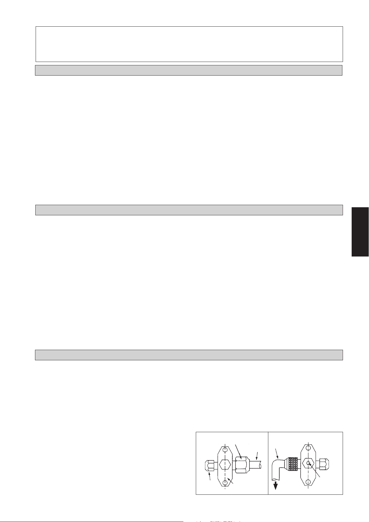
! Cautela
Accertarsi che i collegamenti dei fili dell’unità esterna e dell’unità interna corrispondano ai colori delle rispettive
morsettiere.
PRECAUZIONI SPECIALI QUANDO SI OCCUPANO DELL'UNITÀ DI R410A
R410A è un nuovo refrigerante di HFC che non danneggia
lo strato di ozono. La pressione di esercizio di questo nuovo
refrigerante è 1.il refrigerante 6 volte più superiore
convenzionale (R22), così installation/servicing adeguato è
essenziale.
• Mai refrigerante di uso tranne R410A in un
condizionatore dell'aria che è destinato per funzionare
con R410A.
• L'olio di POE è usato come lubrificante per il copressor
di R410A, che è differente dall'olio minerale usato per il
compressore R22. Durante installazione o l'assistenza,
la precauzione supplementare deve essere presa per non
esporre il sistema di R410A troppo lungo ad aria umida..
L'olio residuo di POE nelle condutture ed il cn dei
componenti assorbono l'umidità dall'aria.
• Impedire mischarging, il diametro dell'orificio di servizio
sulla valvola del chiarore è differente da quello di R22.
PRECAUZIONI SPECIALI QUANDO SI OCCUPANO DELL’UNITÀ DI R407C
• R407C è una miscela refrigerant zeotropic che ha
potenziale zero di svuotamento dell’ozono e stata
conforme così alla regolazione di protocollo de Montreal.
Richiede l’olio dell’olio dell’estere del polyol (POE) per
il lubrificante del relativo compressore. La relative
capienza e prestazioni refrigerant sono più o meno come
il refrigerante R22.
• L’olio di POE è usato come lubrificante per il
compressore di R407C, che è differente dall’olio minerale
usato per il compressore R22. Durante installazione o
l’assistenza, la precauzione supplementare deve essere
presa per non esporre il sistema di R407C troppo lungo
ad aria umida. L’olio residuo di POE nelle condutture ed
i componenti possono assorbire l’umidità dall’aria.
• Il refrigerante R407C è influenzato più facilmente da
polvere di umidità rispetto a R22, si assicura
temporaneamente riguardare le estremità della tubazione
prima di installazione.
• Usi gli attrezzi ed i materiali esclusivamente per il
refrigerante R410A. Gli attrezzi esclusivamente per
R410A sono valvola molteplice, tubo flessibile
caricantesi, manometro, rivelatore della perdita del gas,
attrezzi del chiarore, chiave da coppia di torsione,
pulsometro e cilindro del refrigerante.
• Poichè un condizionatore dell'aria di R410A subisce l'più
alta pressione che le unità R22, è essenziale per scegliere
correttamente i tubi di rame. Mai diluente di rame dei
tubi dell'utente che 0,8mm anche se sono disponibili nel
mercato.
• Se il gas del refrigerante propaga durante l'installazione/
servicing, sia sicuro arieggiare completamente. Se il gas
refrigerant entra in contatto con fuoco, un gas tossico
può accadere.
• Nell'installare o rimuovendo un condizionatore dell'aria,
non lasci che l'aria o l'umidità rimanga nel ciclo
refrigerant.
• Nessuna carica supplementare dell’olio del compressore
è consentita.
• Nessun altro refrigerante tranne R407C.
• Attrezzi specificamente per R407C soltanto (non deve
essere usato per R22 o l’altro refrigerante)
i) Calibro molteplice e tubo flessibile caricantesi
ii) Rivelatore della perdita del gas
iii) Cilindro refrigerant di cylinder/charging
iv) Adattatore del pulsometro c/w
v) Attrezzi del chiarore
vi) Macchina refrigerant di recupero
• L’Filtro-essiccatore deve essere installato seguendo la
linea liquida per tutti i condizionatori dell’aria di R407C.
Ciò deve minimizzare la contaminazione di umidità e di
sporcizia nel sistema refrigerant. L’Filtro-essiccatore deve
essere del tipo del setaccio molecolare. Per un sistema
del heat-pump, installi un essiccatore bidirezionale del
filtrante di flusso seguendo la linea liquida.
Italiano
PURGA DEI TUBI DI REFRIGERANTE
Spurgo Delle Tubazioni El Del Blocco Interno
Fatta eccezione del blocco esterno che è precaricato con il
refrigerante, il blocco interno e le tubature di collegamento
devono essere spurgate dell’aria. Essa contiene infatti dei residui
di umidità prodotti dal ciclo di raffreddamento che possono
provocare un malfunzionamento del compressore.
L’unità esterna è dotata da valvole di connessione di
refrigerazione di 3 vie. La più grande è la valvola di aspirazione,
la più piccola è la valvola del liquido. Entrambe valvole sono
fornite dotate da valvole saracinesca per servizio della
connessione a un manometro.
• Togliere i tappi dalla valvola e dalla bocchetta di servizio.
• Collegare il centro della valvola del collettore alla pompa di
estrazione.
• Collegare la valvola del collettore alla bocchetta di servizio
della valvola a 3 vie.
• Iniziare la pompa a vacuo. Verificare se il manometro della
distribuzione pressione bassa indica 0,9 bar. Il tempo di
scarica varia in funzione della capacità di ogni pompa a vacuo,
ma in genere è circa mezz'ora.
• Chiudere la valvola di distribuzione e fermare la pompa a
vacuo.
• Nell’unità esterna, aprire l’aspirazione e la valvola del liquido
(senso antiorario) con una chiave a brugola da 4 mm.
• L’apparecchio di aria condizionata sarà pronto per l'uso.
• Se il valore letto è prossimo al 0, sarà necessario svuotare il
circuito refrigerante (tramite la pompa a vacuo) e ricaricarlo.
Dadi Di
Svaso
Bocchetta
Di Servizio
Condotti Del
Refrigerante
Valvola a 3 Vie
Del Blocco
Esterno
Tubo Flessibile
4-9
Chiave
Allen Da
4 mm
Page 58

Unità Esterno
Valvola Liquidi
Valvola
Aspirante
Condotti Del
Refrigerante
Indicatore Di Bassa
Pressione
Collettore
Unità Interno
Indicatore Di Alta Pressione
Tubo Flessibile
Pompa Di Estrazione
RICARICA ADDIZIONALE
Il blocco esterno è provvisto del refrigerante, precaricato in fabbrica.
Se la lunghezza del tubo è inferiore a 5 m, dopo l'aspirazione non è
necessaria alcuna ricarica addizionale. Se la lunghezza dei condotti
è superiore ai 5m, usare i valori di ricarica addizionale come indicato
nella tabella in basso.
Operazioni Di Ricarica Addizionale
Tale operazione deve essere obbligatoriamente effettuata utlizzando
il cilindro del gas ed una bilancia di precisione. Il gas refrigerante
viene introdotto nel blocco esterno tramite la bocchetta di servizio
della valvola aspirante.
• Rimuovere il tappo della bocchetta di servizio.
• Collegare il distributore di pressione bassa alla valvola saracinesca
di servizio di aspirazione, il distributore centrale al serbatoio
cilindrico e chiudere il distributore di pressione alta (vedere la
seguente figura).
Purgare tutti i tubi flessibili contenenti gas refrigerante.
• Mettere in funzione il condizionatore.
• Aprire il cilindro del gas e la valvola del collettore a bassa
pressione.
• Quando la quantità richiesta di refrigerante è stata pompata
nell’impianto, chiudere la valvola del collettore a bassa pressione
e la valvola del cilindro del gas.
• Scollegare il tubo flessibile dalla bocchetta di servizio. Rimettere
il tappo della bocchetta di servizio.
Unità Con Pompa Di Riscaldamento (Unità di riscaldamento)
(R410A)
Modelli 7 m 10 m 15 m 20 m
CC 10CR 36 90 – –
CC 15CR 36 90 – –
CC 20CR 45 112 225 –
CC 25CR 90 225 450 –
CC 28CR / CC 30CR 90 225 450 675
CC 38CR / CC 40CR 90 225 450 675
CC 50CR 90 225 450 675
CC 60CR 90 225 450 675
Unità Soltanto Di Refrigerazione (Unità di raffreddamento)
(R22/R407C)
Modelli 7 m 10 m 15 m 20 m
CC 10C 30 75 – –
CC 15C 30 75 – –
CC 20C 30 75 150 –
CC 25C 76 190 380 –
CC 28C / CC 30C 100 250 500 750
CC 38C / CC 40C 100 250 500 750
CC 50C 100 250 500 750
CC 60C 100 250 500 750
Unità Soltanto Di Refrigerazione (Unità di raffreddamento)
(R410A)
Modelli 7 m 10 m 15 m 20 m
CC 10C 27 67 – –
CC 15C 27 67 – –
CC 20C 27 67 135 –
CC 25C 68 171 342 –
CC 28C / CC 30C 90 225 450 675
CC 38C / CC 40C 90 225 450 675
CC 50C 90 225 450 675
CC 60C 90 225 450 675
Unità Con Pompa Di Riscaldamento (Unità di riscaldamento)
(R22/R407C)
Modelli 7 m 10 m 15 m 20 m
CC 10CR 40 100 – –
CC 15CR 40 100 – –
CC 20CR 50 125 250 –
CC 25CR 100 250 500 –
CC 28CR / CC 30CR 100 250 500 750
CC 38CR / CC 40CR 100 250 500 750
CC 50CR 100 250 500 750
CC 60CR 100 250 500 750
4-10
Page 59

Verificare Le Perdite Di Refrigerante
Verificare tramite sensore di refrigerante l'esistenza di perdite nelle connessione del tipo saldato sia nell'unità interna che in quella esterna.
Consigli: Dopo un certo tempo di operazione, verificare l'esistenza di tracce d'olio e di perdite.
Unità Esterno
Condotti Del
Valvola Liquidi
Valvola
Aspirante
Refrigerante
Indicatore Di Bassa
Pressione
Collettore
Tubo Flessibile
Unità Interno
Indicatore Di Alta Pressione
Serbatoio Di Gas Refrigerante
PRECAUZIONI SPECIALI PER LA CARICA DELL’APPARECCHIO CON COMPRESSORI A
SPIRALE ORBITANTE (SCROLL) COPELAND
Queste precauzioni sono indicate per l’utilizzo dei soli compressori a spirale orbitante (Scroll) Copeland con gas refrigeranti
R22, R407C, R134A, R404A, R507 e R410A ma non si applicano ai compressori alternativi (a pistoni) Copeland o ai compressori
a spirale orbitante (Scroll) di altri fabbricanti.
I compressori a spirale orbitante (Scroll) hanno un’efficienza volumetrica molto alta e molto rapidamente creano un alto vuoto
se non c’è sufficiente refrigerante nell’impianto oppure se il refrigerante viene aggiunto troppo lentamente. Il funzionamento
con una pressione di aspirazione bassa porta rapidamente a temperature di scarico molto alte. Durante questo processo le
spirali non vengono lubrificate bene - le spirali necessitano l’olio contenuto nel refrigerante per la lubrificazione. Una mancanza
di lubrificazione porta ad elevata frizione tra il fianco e la punta delle spirali, generando ulteriore calore. La combinazione di
calore dovuto alla compressione e calore dovuto all’incremento di frizione viene concentrata in una piccola area localizzata di
scarico, dove la temperatura può salire rapidamente fino a oltre 300°C. Questa temperatura estrema danneggia le spirali ed i
cuscinetti orbitanti. Tale danno può aver luogo in meno di un minuto, specialmente in compressori più grandi. Il guasto può
accadere nelle prime ore di funzionamento oppure i segni del danno causato durante la carica possono vedersi in un secondo
tempo.
Altri tipici problemi di carica includono sottocarica, sovraccarica, umidità oppure aria nel circuito ecc. Con il tempo ognuno
di questi problemi può provocare il guasto del compressore.
Minime attrezzature sono necessarie per la carica. Tali attrezzature per eseguire un buon lavoro sono:-
Gruppo manometri di servizio Vacuometro
Tubi Bilancia
Pompa a vuoto Termometro
La giusta carica di refrigerante deve rispettare il volume indicato dal fabbricante e tali indicazioni devono essere seguite
dall’installatore.
1. Procedure di carica - Compressori monofase
Vuotare il circuito fino a 500 micron Hg (67 Pa). Per ridurre il tempo di svuotamento utilizzare tubi corti e di grande
diametro, collegati ad un foro libero del circuito. La qualità del vuoto non può essere determinata dal tempo - deve essere
utilizzato un vacuometro affidabile (per es. un vacuometro elettronico).
Capovolgere la bombola del refrigerante, spurgare il tubo di carica e caricare il liquido attraverso il foro di carica della
linea liquido fino a quando il refrigerante non scorre più o fino a raggiungere il peso corretto di carica. Se ci fosse bisogno
di carica aggiuntiva, avviare il sistema and lentamente scaricare liquido nel lato di aspirazione fino a riempire il circuito.
La Copeland consiglia la carica del liquido in modo CONTROLLATO dal lato aspirazione fino a riempire il circuito.
Questa raccomandazione non è valida per compressori alternativi per i quali la carica del liquido dal lato aspirazione
potrebbe provocare gravi danni.
Controllare attentamente la pressione di aspirazione e scarico - assicurarsi che tale pressione non sia mai inferiore a 25 psig
(1,7 bar) durante il processo di carica.
Italiano
4-11
Page 60

! Cautela
• Il gruppo manometri indicherà la pressione della bombola invece della pressione d’aspirazione sel la valvola
della bombola e la valvola “A” sono entrambe aperte.
Ci sono vari sistemi per caricare il liquido in “modo controllato” dal lato aspirazione:-
1. Utilizzare la valvola A sul gruppo manometri
2. Utilizzare la valvola sulla bombola del refrigerante
3. Caricare tramite la valvola Shredder
4. Utilizzare un tubo munito di depressore per la valvola Shredder
5. Caricare dal lato aspirazione ad una cera distanza dal compressore
6. Tutte le procedure di cui sopra
A
2. Procedure di carica – Compressori trifase
La procedura fondamentale è la stessa dei modelli monofase, ma è possibile che il compressore funzioni nella direzione
sbagliata all’avvio. Se ciò dovesse accadere, invertire due delle fasi e riavviare. La rotazione invertita per un breve periodo
non danneggia il compressore.
Tutti i compressori (Modello: da ZR 90 a ZR 19M) Specter sono muniti all’interno di dispositivi di protezione contro il
surriscaldamento di scarico, tali dispositivi sono molto efficaci nel prevenire pericolose alte temperature di scarico durante
la carica. Il modulo di protezione scatta e blocca il compressore per 30 minuti. Normalmente non è necessario attendere 30
minuti per il ripristino del modulo. Quando il compressore è sufficientemente freddo è possibile ripristinare il modulo
interrompendo l’alimentazione elettrica al circuito di controllo. Molto spesso il manutentore non capisce perché il modulo
è intervenuto e utilizza un cavo di connessione provvisorio per escluderlo. Continua a caricare il circuito e toglie il cavo
dopo aver terminato la carica. Il compressore potrebbe anche funzionare con il dispositivo di protezione di nuovo nel
circuito, ma è certo che il compressore è stato danneggiato ed un guasto prematuro diventa inevitabile.
CONTROLLI GENERALI
Verificare in modo particolare i punti seguenti:-
1) L’unità è montata solidamente ed e ben fissata sul posto.
2) Condotti e raccordi risultano a prova di perdite dopo averli
caricati.
3) Gli allacciamenti elettrici sono eseguiti correttamente.
Controllo del drenaggio:- versare un po’ d’acqua sul lato
sinistro del cestello di drenaggio (il drenaggio si trova sul
lato destro dell’unità).
• Prova di funzionamento:
1) Effettuare una prova di funzionamento dopo il controllo
del drenaggio e delle fughe di gas.
CONDIZIONI DI FUNZIONAMENTO STANDARD
Unità di raffreddamento
Temperatura Ts °C / °F Th °C / °F
Temperatura
interna minima
Temperatura
interna massima
Temperatura
esterna minima
Temperatura
esterna massima
19,4/66,9 13,9/57,0
26,7/80,1 19,4/66,9
19,4/66,9 13,9/57,0
46/114,8 24/75,2
2) Fare attenzione alle seguenti questioni:a) La spina del condizionatore è solidamente inserita
nella relativa presa?
b) Il condizionatore emette dei rumori anormali?
c) Il drenaggio funziona correttamente?
• Verificare:
1) Che la ventola del condensatore funziona. Controllare
se l’aria calda esce dall’unità di condensazione.
2) Che il soffiante dell’evaporatore funziona e scarica
aria fredda.
3) Nel controllo mediante telecomando è previsto un ritardo
di 3 minuti. Quindi l’avviamento dell’unità esterna sarà
dopo 3 minuti circa.
Unità di riscaldamento
Temperatura Ts °C / °F Th °C / °F
Temperatura
interna minima
Temperatura
interna massima
Temperatura
esterna minima
Temperatura
esterna massima
10/50 -
26,7/80,1 -
-8/17,6 -9/15,8
24/75,2 18/64,4
Ts: Temperatura a termometro asciutto. Th: Temperatura a termometro bagnato.
! Avvertenza
• Staccare la corrente prima di procedere a qualsiasi intervento di manutenzione sul condizionatore.
• Non rimuovere il cavo di alimentazione quando il condizionatore è acceso. Questo può causare seri
shock elettrici e pericolo d’incendio.
4-12
Page 61

FUNZIONE DI RI-ACCENSIONE CASUALE AUTOMATICA
Una volta che la corrente elettrica (venuta a mancare mentre il condizionatore era in funzione) viene ripristinata, il condizionatore
si riaccenderd rielle stesse condizioni di funzionamento. (Solo per i modelli dotati di questa funzione).
! Cautela
Nel fare operazioni di manutenzione che richiedono la spegnimento dell'alimentazione, spegnere il telecomando a
distanza.
Togliere alimentazione quando l'interruttore del telecomando è sulla posizione ON è pericoloso perchè la funzione di
riavvio automatico (in seguito alla mancanza di corrente) fard riaccendere automaticamente le ventole delle unita
interna ed esterna tre minuti dpop che la corrente elettrica è stata ripristinata.
PULIZIA E MANUTENZIONE
Componenti
Filtro Dell’Aria Interno
Unità Interna
Cestello E Tubo Di
Drenaggio Della Condensa
Ventola Interna
Serpentino Interno
E Esterno
Alimentazione Elettrica
Procedure Di Manutenzione
1. Togliere la polvere dal filtro usando un'aspirapolvere o lavarlo
in acqua tiepida (sotto ai 40˚C) con detersivo neutro.
2. Sciacquare bene e asciugare il filtro prima di rimetterlo
nell'unità.
3. Non usare mai benzina o prodotti chimici per pulire il filtro.
1. Togliere la polvere e la sporcizia dalla griglia e dal pannello,
strofinando con un panno soffice imbevuto di acqua tiepida
(sottoai 40°C) e detersivo neutro.
2. Non usare mai benzina o prodotti chimici per pulire l'unità
interna.
1. Controllare e pulire se necessario.
1. Controllare non faccia rumori anormali.
1. Controllare e togliere eventuale sporcizia ripostasi sulle alette.
2. Controllare e rimuovere eventuali ostacoli alla libera entrata
ed uscita dell'aria dalle unità interna e esterna.
1. Controllare il voltaggio e l'alimentazione delle unità interna e
esterna.
2. Controllare gli allacciamenti elettrici per eventuali contatti
difettosi causati da collegamenti laschi, incrostazioni, ecc.
Stringere i fili sulla morsettiera se necessario.
Frequenza
Almeno due volte
al mese.
Più spesso se
necessario.
Almeno due volte
al mese.
Più spesso se
necessario.
Italiano
Ogni 3 mesi.
Quando necessario.
Ogni mese.
Ogni mese.
Ogni 2 mesi.
Ogni 2 mesi.
Compressore
Olio Del Compressore
Olio Motore Della Ventola
1. Non è necessaria alcuna manutenzione se il circuito
refrigerante resta sigillato. Verificare tuttavia che non vi siano
fughe di gas a livello dei giunti e collegamenti.
1. L'olio del compressore è precaricato in fabbrica. Non è necessaria alcuna aggiunta d' olio se il circuito rimane sigillato.
1. Il motore è prelubricato e sigillato in fabbrica.
Ogni 6 mesi.
Manutenzione non
necessaria.
Manutenzione non
necessaria.
! Cautela
Non utilizzare applarecchiature di riscaldamento nelle immediate vicinanze del condizionatore. L’eccessivo calore
potrebbe danneggiare o deformare il pannello in plastica.
4-13
Page 62

GUASTI E RIPARAZIONI
Non appena si nota che il condizionatore funziona male, spegnerlolo immediatamente. Qui di seguito, sono
elencati alcuni guasti minori con le relative cause.
Guasto
1. Il compressore nom si mette in funzione 3 minuti dopo
aver acceso il condizionatore.
2. Il condizionatore non funziona.
3. Il funsso d'aria è troppo debole.
4. Il display del telecomando non è luminoso.
5. L'aria che esce dal condizionatore ha cattivo odore.
6. Condensa sulla griglia anteriore di ventilazione
dell'unita interna.
Origine
- Protezione contro gli avvii riavvicinati. Attendre 3 or 4
minuti affinchè il compressore si metta in moto.
- Interruzione della corrente o fusibile bruciato.
- La spina non è inserita.
- L'orario impostato sul timer di ritardo non è corretto.
- Se il guaste dopo tali verifiche, chiamare il servizio
assistenza.
- Il filtro dell'aria è sporco.
- Porte e finestre aperte.
- L'aspirazione e lo scarico dell'aria sono ostruiti.
- La temperatura impostata non è sufficientemente bassa.
- Pile scariche.
- Pile male inserite.
- Il cattivo odore può essere causato da sigarette, particelle
di fumo, profumi, ecc. depositati sul serpentino.
- La condensa è dovuta all'umidità dell' aria dopo un lungo
periodo di funzionamento.
- La temperatura impostata è troppo bassa. Aumentare la
temperatura e la velocità della ventola.
7. Acqua sgocciola dal condizionatore.
8. L'aria esce dal condizionatore emettendo un suono
anormale.
- Verificare l'evacuazione della condensa.
- Immissione di refrigerante nel serpentino dell'
evaporatore.
Se il guasto persiste, rivolgersi al servizio di assistenza.
4-14
Page 63

MANUAL DE INSTALACIÓN
Este manual facilita instrucciones de instalación que garantizan un seguro y buen funcionamiento de la unidad
de aire acondicionado.
Es posible que sea necesario realizar un ajuste especial para adecuarse a los requisitos locales.
Por favor, antes de usar su equipo de aire acondicionado, lea cuidadosamwnte este manual de instrucciones, y
consérvelo para futuras consultas.
AIRE ACONDICIONADO SPLIT DE TECHO
MODELO
UNIDAD DE ENFRIAMIENTO
CC10C / ACC10C
SL10B / ALC10B
SL10C / ALC10C
4SL10B / A4LC10B
5SL10C / A5LC10C
CC15C / ACC15C
SL15B / ALC15B
SL15C / ALC15C
4SL15B / A4LC15B
5SL15C / A5LC15C
CC20C / ACC20C
SL20B / ALC20B
4SL20B / A4LC20B
5SL20B / A5LC20B
CC25C / ACC25C
SL25B / ALC25B
4SL25B / A4LC25B
5SL25B / A5LC25B
CC28C / ACC28C
SL30B / ALC30B
SL30C / ALC30C
4SL30C / A4LC30C
5SL30C / A5LC30C
CC30C / ACC30C
SL30B / ALC30B
SL30C / ALC30C
4SL30C / A4LC30C
5SL30C / A5LC30C
CC38C / ACC38C
SL40C / ALC40C
4SL40C / A4LC40C
5SL40C / A5LC40C
CC40C / ACC40C
SL40C / ALC40C
4SL40C / A4LC40C
5SL40C / A5LC40C
CC50C / ACC50C
SL50C / ALC50C
4SL50C / A4LC50C
5SL50C / A5LC50C
CC60C / ACC60C
SL60C / ALC60C
4SL60C / A4LC60C
5SL60C / A5LC60C
MSS60C / AMC60C
CALENTADOR
CC10CR / ACC10CR
SL10BR / ALC10BR
SL10CR / ALC10CR
4SL10BR / A4LC10BR
5SL10CR / A5LC10CR
CC15CR / ACC15CR
SL15BR / ALC15BR
SL15CR / ALC15CR
4SL15BR / A4LC15BR
5SL15CR / A5LC15CR
CC20CR / ACC20CR
SL20BR / ALC20BR
4SL20BR / A4LC20BR
5SL20BR / A5LC20BR
CC25CR / ACC25CR
SL25BR / ALC25BR
4SL25BR / A4LC25BR
5SL25BR / A5LC25BR
CC28CR / ACC28CR
SL30BR / ALC30BR
SL30CR / ALC30CR
4SL30CR / A4LC30CR
5SL30CR / A5LC30CR
CC30CR / ACC30CR
SL30BR / ALC30BR
SL30CR / ALC30CR
4SL30CR / A4LC30CR
5SL30CR / A5LC30CR
CC38CR / ACC38CR
SL40CR / ALC40CR
4SL40CR / A4LC40CR
5SL40CR / A5LC40CR
CC40CR / ACC40CR
SL40CR / ALC40CR
4SL40CR / A4LC40CR
5SL40CR / A5LC40CR
CC50CR / ACC50CR
SL50CR / ALC50CR
4SL50CR / A4LC50CR
5SL50CR / A5LC50CR
CC60CR / ACC60CR
SL60CR / ALC60CR
4SL60CR / A4LC60CR
5SL60CR / A5LC60CR
MSS60CR / AMC60CR
Español
Part No.: A08019025456
IM-CCC-0501(3)-Acson
5-1
Page 64

INDICE
- Esquema y Dimensiones Página i-iv
- Precauciones de Seguridad Página 2
- Diagramma de La Instalación Página 3
- Instalación de la Unidad de Interior Página 3
- Instalación de la Unidad de Exterior Página 4
- Tubería de Refrigerante Página 4
- Conexión del Eléctrico Página 5
- Precauciones Especiales al Ocuparse de la Unidad de R410A Página 9
- Precauciones Especiales al Ocuparse de la Unidad de R407C Página 9
- Purga de los Tubos de Refrigerante Página 9
- Carga Adicional Página 10
- Precauciones Especiales al Cargar la Unidad con Los Compresores Scroll Copeland Página 11
- Verificación General Página 12
- Condicion de Funcionamiento Estándar Página 12
- Funcion Del Arranque Automatico Casual Página 13
- Reparaciones y Mantenimiento Página 13
- Localizacón de Averias Página 14
PRECAUCIONES DE SEGURIDAD
Antes de instalar su equipo, sírvase leer las siguientes precauciones de seguridad cuidadosamente.
! Advertencia
• La instalación y el mantenimiento deben ser realizador por personas calificadas que estén familiarizadas con el
código y los reglamentos locales y que tengan experiencia en este tipo de equipo.
• Todo el cableado de campo debe instalarse de acuerdo al reglamento de cableado nacional.
• Antes de comenzar la instalación eléctrica de acuerdo con el diagrama de cableado, asegúrese de que el voltaje
nominal de la unidad se corresponde con el de la place de identificación.
• La unidad debe estar PUESTA A TIERRA para evitar posibles peligros debidos a fallas del aislamiento.
• Ninguno delos cables de la instalación eléctrica dene estar en contacto con la tubería refrigerante, el compresor o
cualquier pieza móvil de los motores del ventilador.
• Antes de iniciar la instalación o reparación de la unidad, asegúrese de que ha sido apagara (OFF).
IMPORTANTE
NO INSTALE NI HAGA USO DE LA UNIDAD DE AIRE ACONDICIONADO EN UN CUARTO
DESTINADO A LAVAR ROPAS.
! Cuidado
Asegúrese de seguir durante la instalación los siguientes puntos importantes.
• No instalar la unidad ahí donde pueda haber fuga de gas inflamable.
Siel gas procedente de una fuga de gas se acumula alrededor de la unidad puede producirse unincendio.
• Asegúrese de que la tubería de desagüe está conectada correctamente.
Si la tubería de desagüe no está conectada correctamenta se puede producir una fuga de agua que
mojaría los muebles.
• No sobrecargar la unidad.
Esta unidad está pre-cargada en fábrica. Su sobrecarga ocasionará sobre-corrinte o rotura del compresor.
• Asegúrese de que el panel de la unidad vuelve a cubrirla, bien colocado, después de la instalación
o de cualquier reparación.
Un panel mal sujetado hará que la unidad haga ruido al funcionar.
5-2
Page 65

Unidad Interior
Entrada De Aire
DIAGRAMMA DE LA INSTALACIÓN
Entrada De Aire
Tubería De
Refrigerante
Tobera De Descarga De Aire
INSTALACIÓN DE LA UNIDAD DE INTERIOR
La unidad interior debe instalarse de modo que no se
produzca ningún cortocircuito de la descarga de aire frío.
Respete la distancia de instalación. No coloque la unidad
interior expuesta a la luz solar directa. La ubicación debe
ser la adecuada para las tuberías y drenaje y con una distancia
amplia entre la unidad y cualquier puerta.
Montaje Del Aire Acondicionado De Tech
– Utilice el soporte colgante que se incluye con la unidad.
– Asegúrese de que el techo tiene la resistencia suficiente
para soportar el peso.
Distancia al centro del eje (ver gráfico a continuación).
A
Unidad Exterior
CC
A mm (pulgadas) L mm (pulgadas)
10 C/CR 741 (29,2) 225 (8,9)
15 C/CR 881 (34,7) 225 (8,9)
20 C/CR 1041 (41,0) 225 (8,9)
25 C/CR 1176 (46,3) 225 (8,9)
28 C/CR 959 (37,8) 339 (13,3)
30 C/CR 956 (37,6) 266 (10,5)
38 C/CR 1264 (49,8) 401 (15,8)
40 C/CR 1076 (42,4) 266 (10,5)
50 C/CR 1326 (52,2) 266 (10,5)
60 C/CR 1526 (60,1) 266 (10,5)
Mantenga una distancia para facilitar los trabajos y
mantenimiento y una circulación del aire óptima, según se
muestra en el gráfico.
Español
L
10 mm (32,8)
10 mm (32,8)
5-3
Page 66

INSTALACIÓN DE LA UNIDAD DE EXTERIOR
La unidad exterior debe instalarse de tal modo que no se produzca
ningún cortocircuito del aire de descarga u obstrucción de un caudal de aire uniforme. Respete las distancias de instalación.
Seleccione el lugar más fresco posible donde la temperatura del
aire de entrada no sea superior a la temperatura exterior (máximo
45ºC).
Asegúrese de que no hay obstrucciones en la corriente de aire o
fuera de la unidad. Elimine los posibles obstáculos que bloqueen la
admisión o descarga de aire.
Espacio Libre En Torno A La Unidad De Exterior Series
SL (en mm)
300
Aire De Retorno
Obstaculo
300 500
1000
Aire De
Descarga
Obstaculo
La ubicación debe disponer de una buena ventilación, de modo que
la unidad pueda distribuir una elevada cantidad de aire y bajar la
temperatura.
Elija un lugar capaz de soportar el peso de la unidad de exterior, así
como de aislar el ruido y la vibración.
El emplazamiento no debe recibir luz solar directa. De lo contrario,
use un toldillo protector.
El emplazamiento elegido para la instalación no debe ser susceptible
de acumular una alta concentración de polvo, aceite, sal o gases
sulfurosos.
TUBERÍA DE REFRIGERANTE
Longitud Maxima De La Tubería y Numero Maximo
De Curvas
Cuando la longitud del tubo sea demasiado larga, se reducirán la
capacidad y la fiabilidad. Según se incremente el número de codos,
se incrementa la resistencia de los conductos del sistema al flujo de
refrigerante, reduciéndose la capacidad de refrigeración. Elija
siempre el recorrido más corto y siga las recomendaciones que se
indican más adelante:
Modelo
Datos
Long. máx, A m (pies)
Elevación máx, B m (pies)
N˚ máx. de curvas, C 10 10 10 10 10
10 15 20 25 28
12 12 15 15 35
(39,4) (39,4) (49,2) (49,2) (114,8)
558810
(16,4) (16,4) (26,2) (26,2) (32,8)
Acess De
Servicio
Aire De Retorno
Obstaculo
Obstaculo
Nota:- Si hay algún obstáculo superior a dos metros o si hay alguna
obstrucción en la parte superior de la unidad, entonces deje
más espacio que el indicado en la tabla.
A
C
B
Modelo
Datos
Long. máx, A m (pies)
Elevación máx, B m (pies)
30 38 40 50 60
35 35 35 35 35
(114,8)(114,8)(114,8)(114,8) (114,8)
10 10 10 10 10
(32,8) (32,8) (32,8) (32,8) (32,8)
N˚ máx. de curvas, C 10 10 10 10 8
Observación: para la unidad refrigeradora CC60C, se
recomienda añadir 6 kg de acumulador externo.
5-4
A
C
B
C
Page 67

Instalación De Tuberías y Tecnica De Abocinamiento
No utilice tubos de cobre contaminados o dañados. Si cualquiera de
los tubos, evaporador o condensador ha estado expuesto o abierto
durante 15 segundos o más tiempo, limpie el sistema con aspiración.
Generalmente, no retire los plásticos, tapones de goma y tuercas de
latón de las válvulas, empalmes, tubos y serpentines hasta estar
preparado para su conexión.
Si es necesario algún trabajo de cobresoldadura, asegúrese de hacer
pasar gas nitrógeno a través de los tubos y juntas mientras realiza el
trabajo de soldadura. De este modo, se evitará la formación de hollín
en las paredes interiores de los tubos de cobre.
Corte la tubería paso a paso, haciendo avanzar la cuchilla del cortador
de tubos lentamente. Un exceso de fuerza y un corte profundo
producirían una mayor deformación de la tubería y, por lo tanto, más
rebabas.
Elimine la rebabas de los bordes de corte según se muestra en la Figura
R. Así, evitará irregularidades en la parte ancha que pueden producir
fugas de gas. Sujete el tubo por su parte superior y la herramienta
quitarrebabas en la posición inferior para evitar que las virutas metálicas
se introduzcan en el tubo.
Inserte las tuercas abocinadas, montadas sobre las partes de la conexión
tanto de la unidad de interior como de la unidad de exterior, en las
tuberías de cobre.
La longitud exacta de la tubería que sobresale de la cara de la matriz de
abocinamiento se determina mediante una herramienta de
abocinamiento.
Fije la tubería firmemente sobre la matriz de abocinamiento. Alinee
los centros de la matriz de abocinamiento y del punzón de
abocinamiento, y apriete entonces el punzón de abocinamiento
completamente.
Conexión De Las Tuberías a Las Unidades
Alinee el centro de la tubería y apriete suficientemente la tuerca
abocinada con los dedos.
Finalmente, apriete la tuerca abocinada con la llave dinamométrica
hasta que la llave haga “clic”.
Al apretar la tuerca abocinada con la llave dinamométrica, asegúrese
de que aprieta en el sentido indicado por la flecha de la llave.
Las conexiones de los tubos de refrigerante están aisladas con
poliuretano (tipo ARMAFLEX o similar).
Ø Tubo, D A (mm)
Pulgada mm Imperial Rigido
1/4" 6,35 1,3 0,7
3/8" 9,52 1,6 1,0
1/2" 12,70 1,9 1,3
5/8" 15,88 2,2 1,7
3/4" 19,05 2,5 2,0
Tamaño De La Tubería, mm(Pulgadas) Par (Nm)
6,35 (1/4) 18
9,53 (3/8) 42
12,7 (1/2) 55
15,88 (5/8) 65
19,05 (3/4) 78
Junta Abocinada
Tubo Abocinada
Corte Del Tubo De Cobre
1/4t
Tubo De Cobre
Fig. R
Retirar Las Rebabas
Tubo De Cobre
Bloque De Estampar
! Cuidado
Tubería De Interior
Llave De Tuercas
Tuerca Abocinada
Llave Dinamométrica
CONEXIÓN DEL ELÉCTRICO
Asegúrese de que el color de los cables de la unidad de exterior y de las marcas de
los terminales sean, respectivamente, iguales a los de la unidad de interior.
Español
Las unidades para sólo refrigeración, CC 10 / 15 / 20 / 25 C
Unidad de interior CC 10C CC 15C CC 20C CC 25C
Unidad de exterior SL 10B SL 15B SL 20B SL 25B
Margen de la tensión**
220V – 240V /1Ph /50Hz + ! o 208V–230V /1Ph /60Hz + !
Fusible recomendado* A 10 10 16 20
Tamaño del cable de alimentación* mm
2
1,5 1,5 2,5 2,5
Número de conductores 33 3 3
Tamaño del cable de interconexión* mm
2
1,5 1,5 2,5 2,5
Número de conductores 33 3 3
5-5
Page 68

CC 10 / 15 / 20 / 25 C - SL 10 / 15 / 20 / 25 B
CC 28 / 30 C - SL 30 B
COMP
L
COMP
Regleta De Terminales
Unidad De Exterior
N
Regleta De Terminales
Unidad De Interior
N
!
N
!
!
Las Unidades Para Sólo Refrigeración, CC 28 / 30 C
Unidad de interior CC 28 / 30C
Unidad de exterior SL30B SL30C
Margen de la tensión** 220V–240V / 1Ph / 50Hz + ! o 208V–230V / 1Ph / 60Hz + !
Fusible recomendado* A 25 25
Tamaño del cable de alimentación* mm
Número de conductores 33
Tamaño del cable de interconexión* mm
Número de conductores 34
CC 28 / 30 C - SL 30 C
Regleta De Terminales
Unidad De Interior
Debe haber un interruptor bipolar
con un mínimo de 3 mm de espacio
de contacto y fusibe/ruptor de circuito,
!
tal y como se recomienda en el circuito
de instalacíon fija.
2
2
El Cabel Del
Enchuffe
COMP
L
N
N
!
!
El Cabel Del
Enchuffe
Debe haber un interruptor bipolar con un mínimo de
3 mm de espacio de contacto y fusibe/ruptor de
circuito, tal y como se recomienda en el circuito de
!
instalacíon fija.
4,0 4,0
2,5 2,5
L
Regleta De Terminales
Unidad De Exterior
N
!
S
R
COMP
L
N
!
Las Unidades Para Sólo Refrigeración, CC 38 / 40 / 50 / 60 C
Unidad de interior
Unidad de exterior
Margen de la tensión**
Fusible recomendado*
Tamaño del cable de alimentación*
(50/ 60Hz) A 10/20 16/25 16/25
(50/ 60Hz) mm
380V– 415V /3Ph /50Hz +N + ! o 208V–230V / 3Ph /60Hz + N + !
Número de conductores
Tamaño del cable de interconexión*
mm
Número de conductores
IMPORTANTE: * Los valores mostrados arriba se dan a título informativo únicamente. Estos deben ser verificados y
seleccionados a fin de que cumplan con los códi gos y reglamentos locales y/o nacionales. También
están sujetos al tipo de instalación y al tamaño de los conductores.
** Compruebe el voltaje adecuado en la etiqueta de características del aparato. La unidad marcada como
ETL (Marcas para Productos Certificados) es aplicable solamente a una fuente de alimentación de
60 Hz.
CC38 / 40C CC50C CC60C
SL 40C SL 50C SL 60C o MSS60C
2
2
1,5/2,5 2,5/4,0 2,5/4,0
55 5
1,5/1,5 1,5/1,5 1,5/1,5
44 4
5-6
Page 69

CC 38 / 40 / 50 / 60 C - SL 40 / 50 / 60 C
COMP
L
N
!
Regleta De Terminales
Unidad De Exterior
Regleta De Terminales
Unidad De Interior
COMP
L
N
!
R
S
Debe haber un interruptor bipolar con
un mínimo de 3 mm de espacio de
!
contacto y fusibe/ruptor de circuito, tal
y como se recomienda en el circuito de
instalacíon fija.
Las Unidades De Bomba De Calor, CC 10 / 15 / 20 / 25 CR
El Cabel Del Enchuffe
T
N
!
Unidad de interior CC 10CR CC 15CR CC 20CR CC 25CR
Unidad de exterior SL 10BR SL 15BR SL 20BR SL 25BR
Margen de la tensión**
220V – 240V /1Ph /50Hz + !
o 208V–230V /1Ph /60Hz + !
Fusible recomendado* A 10 10 16 20
Tamaño del cable de alimentación* mm
2
1,5 1,5 2,5 2,5
Número de conductores 33 33
Tamaño del cable de interconexión* mm
2
1,5 1,5 2,5 2,5
Número de conductores 55 55
CC 10 / 15 / 20 / 25 CR - SL 10 / 15 / 20 / 25 BR
Sensor Del Serpentín De Exterior
Regleta De Terminales
Unidad De Interior
4WV
OF
COMP
4WV
Regleta De Terminales
Unidad De Exterior
OF
COMP
L
N
N
!
!
Las Unidades De Bomba De Calor, CC 28 / 30 CR
El Cabel Del Enchuffe
N
!
Debe haber un interruptor bipolar con
un mínimo de 3 mm de espacio de
!
contacto y fusibe/ruptor de circuito, tal
y como se recomienda en el circuito de
instalacíon fija.
Unidad de interior CC 28/30 CR
Unidad de exterior SL 30BR SL 30CR
Margen de la tensión** 220V–240V /1Ph /50Hz + ! o 208V–230V /1Ph /60Hz + !
Fusible recomendado* A 25 25
Tamaño del cable de alimentación* mm
2
4,0 4,0
Número de conductores 33
Tamaño del cable de interconexión* mm
2
2,5 2,5
Número de conductores 56
Español
IMPORTANTE: * Los valores mostrados arriba se dan a título informativo únicamente. Estos deben ser verificados y
seleccionados a fin de que cumplan con los códi gos y reglamentos locales y/o nacionales. También
están sujetos al tipo de instalación y al tamaño de los conductores.
** Compruebe el voltaje adecuado en la etiqueta de características del aparato. La unidad marcada como
ETL (Marcas para Productos Certificados) es aplicable solamente a una fuente de alimentación de
60 Hz.
5-7
Page 70

CC 28 / 30 CR - SL 30 BR
Debe haber un interruptor bipolar con
!
un mínimo de 3 mm de espacio de
contacto y fusibe/ruptor de circuito, tal
y como se recomienda en el circuito de
instalacíon fija.
Regleta De Terminales
Unidad De Interior
Sensor Del Serpentín De Exterior
A
4WV
OF
COMP
L
N
N
!
!
4WV
OF
Regleta De
COMP
Terminales Unidad
De Exterior
N
!
El Cabel Del Enchuffe
CC 28 / 30 CR - SL 30 CR
Sensor Del Serpentín De Exterior
A
4WV
OF
Regleta De Terminales
Unidad De Interior
COMP
L
N
N
Debe haber un interruptor bipolar con
!
un mínimo de 3 mm de espacio de
contacto y fusibe/ruptor de circuito, tal
y como se recomienda en el circuito de
instalacíon fija.
Las Unidades De Bomba De Calor, CC 38 / 40 / 50 / 60 CR
Unidad de interior
!
!
CC 38 / 40CR CC 50CR CC 60CR
Unidad de exterior
Margen de la tensión**
380V– 415V /3Ph /50Hz +N + ! o 208V – 230V /3Ph /60Hz + N + !
El Cabel Del Enchuffe
SL 40CR SL 50CR SL 60CR o MSS 60CR
A
4WV
OF
Regleta De
COMP
Terminales Unidad
De Exterior
L
N
!
L
N
!
Fusible recomendado* (50/60Hz) A 10/20 16/25 16/25
Tamaño del cable de alimentación
* (50/60Hz) mm
Número de conductores
Tamaño del cable de interconexión
* (50/60Hz) mm
2
1,5/2,5 2,5/4,0 2,5/4,0
55 5
2
1,5/1,5 1,5/1,5 1,5/1,5
Número de conductores 77 7
CC 38 / 40 / 50 / 60 CR - SL 40 / 50 / 60 CR
Regleta DeTerminales
Unidad De Interior
Debe haber un interruptor bipolar con
!
un mínimo de 3 mm de espacio de
contacto y fusibe/ruptor de circuito, tal
y como se recomienda en el circuito de
instalacíon fija.
IMPORTANTE:*
Los valores mostrados arriba se dan a título informativo únicamente. Estos deben ser verificados y seleccionados a fin de que cumplan con los
códi gos y reglamentos locales y/o nacionales. También están sujetos al tipo de instalación y al tamaño de los conductores.
**
Compruebe el voltaje adecuado en la etiqueta de características del aparato. La unidad marcada como ETL (Marcas para Productos Certificados)
es aplicable solamente a una fuente de alimentación de 60 Hz.
Sensor Del Serpentín De Exterior
A
4WV
OF
COMP
L
N
!
El Cabel Del Enchuffe
5-8
A
4WV
OF
COMP
L
Regleta De
Terminales Unidad
N
De Exterior
!
R
S
T
N
!
Page 71

! Cuidado
Asegúrese de que el color de los cables de la unidad de exterior y de las marcas de los terminales sean, respectivamente,
iguales a los de la unidad de interior.
PRECAUCIONES ESPECIALES AL OCUPARSE DE LA UNIDAD DE R410A
R410A es un refrigerante nuevo de HFC que no daña la capa
de ozono. La presión de funcionamiento de este refrigerante
nuevo es 1.el refrigerante 6 veces más arriba que convencional
(R22), así installation/servicing apropiado es esencial.
• Nunca refrigerante del uso con excepción de R410A en un
acondicionador de aire que se diseña para funcionar con
R410A.
• El aceite de POE se utiliza como lubricante para el copressor
de R410A, que es diferente del aceite mineral usado para
el compresor R22. Durante la instalación o el
mantenimiento, la precaución adicional se debe tomar para
no exponer el sistema de R410A demasiado largo al aire
húmedo. El aceite residual de POE en la tubería y el cn de
los componentes absorben la humedad del aire.
• Evitar mischarging, el diámetro del puerto del servicio en
la válvula de la llamarada es diferente de el de R22.
PRECAUCIONES ESPECIALES AL OCUPARSE DE LA UNIDAD DE R407C
• R407C es una mezcla refrigerante zeotropic que tiene
potencial cero del agotamiento del ozono y conformada
así con la regulación del protocolo de Montreal. Requiere
el aceite del aceite del éster del polyol (POE) para el
lubricante de su compresor. Su capacidad y funcionamiento
refrigerantes están casi como el refrigerante R22.
• El aceite de POE se utiliza como lubricante para el
compresor de R407C, que es diferente del aceite mineral
usado para el compresor R22. Durante la instalación o el
mantenimiento, la precaución adicional se debe tomar para
no exponer el sistema de R407C demasiado largo al aire
húmedo. El aceite residual de POE en la tubería y los
componentes pueden absorber la humedad del aire.
• El refrigerante R407C es afectado más fácilmente por el
polvo de la humedad comparado con R22, se cerciora de
cubrir temporalmente los extremos de la tubería antes de la
instalación.
• Utilice las herramientas y los materiales exclusivamente
para el refrigerante R410A. Las herramientas para R410A
son exclusivamente válvula mul'tiple, manguera de carga,
galga de presión, detector del escape del gas, herramientas
de la llamarada, llave de esfuerzo de torsión, bomba de
vacío y cilindro del refrigerante.
• Pues un acondicionador de aire de R410A incurre en una
presión más alta que las unidades R22, es esencial elegir
las pipas de cobre correctamente. Nunca deluente de cobre
de las pipas del usuario que 0,8m m aunque están
disponibles en el mercado.
• Si el gas del refrigerante se escapó durante la instalación /
servicing, sea seguro ventilar completamente. Si el gas
refrigerante viene en contacto con el fuego, un gas venenoso
puede ocurrir.
• Al instalar o quitando un acondicionador de aire, no permita
que el aire o la humedad permanezca en el ciclo refrigerante.
• No se permite ninguna carga adicional de aceite del
compresor.
• Ningún otro refrigerante con excepción de R407C.
• Herramientas específicamente para R407C solamente (no
debe ser utilizado para el R22 o el otro refrigerante)
i) Galga mul’tiple y manguera de carga
ii) Detector del escape del gas
iii) Cilindro refrigerante de cylinder/charging
iv) Adaptador de la bomba de vacío c/w
v) Herramientas de la llamarada
vi) Máquina refrigerante de la recuperación
• El Filtro-secador se debe instalar a lo largo de la línea líquida
para todos los acondicionadores de aire de R407C. Éste
debe reducir al mínimo la contaminación de la humedad y
de la suciedad en el sistema refrigerante. el Filtro-secador
debe estar de tipo del tamiz molecular. Para un sistema del
heat-pump, instale un secador de dos vías del filtro del flujo
a lo largo de la línea líquida.
Español
PURGA DE LOS TUBOS DE REFRIGERANTE
Limpieza De La Tubería Y La Unidad De Interior
Salvo la unidad de exterior que esta precargada con
refrigerante, se debe limpiar con chorro de aire la unidad de
interior y las tuberías de conexión de refrigerante puesto que
el aire que contiene humedad que queda en el ciclo del
refrigerante puede causar un funcionamiento defectuoso del
compresor.
La unidad exterior está equipada con dos válvulas de
conexión de refrigeración de 3 direcciones. La válvula de
aspiración es la más grande y la válvula de líquidos es la
más pequeña. Ambas válvulas incluyen con una válvula en
el puerto de servicio para su conexión a un manómetro.
• Retirar las tapas de la válvula y del agujero de servicio.
• Conecte el centro del calibrador de carga a la bomba de
vacío.
• Conecte el calibrador de carga al orificio de servicio de la
válvula de 3 vías.
• Ponga en marcha la bomba de vacío. Compruebe que el
distribuidor de baja presión indica 0,9 bar. El tiempo de
evacuación varía con la capacidad de cada bomba de vacío
pero, generalmente, en su mitad en una hora.
• Cierre la válvula distribuidora y pare la bomba de vacío.
• En la unidad exterior, abra la válvula de aspiración y
válvula de líquidos (sentido antihorario) girando el
tornillo hexagonal con una llave de 4 mm.
• El aire acondicionado está preparado para su puesta en
marcha.
• Si la lectura es cercana a 0, debe vaciarse el circuito de
refrigerante (con la bomba de vacío) y cargarse de nuevo.
Menguera
Flexible
Agujero de
Servicio
Tubería de
Tuerca
Refrigerante
Abocinada
Válvula de 3 vías de
la unidad el exterior
5-9
Llave
Allen de
4 mm
Page 72

Unidad De Exterior
Tubería de Refrigerante
Válvula De Liquido
Indicatore Di
Válvula De
Gas
Bassa Pressione
Collettore
CARGA ADICIONAL
El refrigerante está precargado en la unidad de exterior. Si la
longitud de la tubería es inferior a 5 m, no es necesaria una
carga adicional después de la aspiración. Si la longitud de la
tubería es de más de 5 m, siga los valores de carga adicional
tal y como se indica en la tabla a continuación.
Operación de carga adicional
Esta operación se debe realizar usando un cilindro de gas y
una máquina de pesaje obligatoriamente. La carga adicional
se introduce en la unidad de exterior por la válvula de
aspiración a través del agujero de servicio.
• Retirar el tapón del agujero de servicio.
• Conecte el distribuidor de baja presión al puerto de servicio
de aspiración, el distribuidor central al depósito del cilindro
y cierre el distribuidor de alta presión (ver figura a
continuación).
Purgue toda la manguera flexible con gas refrigerante.
• Poner en marcha la unidad de aire acondicionado.
• Abrir la válvula del cilindro de gas y la de cierre de baja
presión.
• Cuando se haya bombeado la unidad con la cantidad de
refrigerante requerida, cerrar la válvula de baja presión y
del cilindro de gas.
• Desconectar la manguera de servicio del agujero de
servicio. Volver a colocar la tapa del agujero de servicio.
Unidad De Interior
Indicatore Di
Altapressione
Menguera
Flexible
Pompa De Vacío
Carga Adicional En Gramos (Unidad de Calentamiento)
(R410A)
Modelo 7 m 10 m 15 m 20 m
CC 10CR 36 90 – –
CC 15CR 36 90 – –
CC 20CR 45 112 225 –
CC 25CR 90 225 450 –
CC 28CR / CC 30CR 90 225 450 675
CC 38CR / CC 40CR 90 225 450 675
CC 50CR 90 225 450 675
CC 60CR 90 225 450 675
Carga Adicional En Gramos (Unidad de Enfriamiento)
(R22/R407C)
Modelo 7 m 10 m 15 m 20 m
CC 10C 30 75 – –
CC 15C 30 75 – –
CC 20C 30 75 150 –
CC 25C 76 190 380 –
CC 28C / CC 30C 100 250 500 750
CC 38C / CC 40C 100 250 500 750
CC 50C 100 250 500 750
CC 60C 100 250 500 750
Carga Adicional En Gramos (Unidad de Enfriamiento)
(R410A)
Modelo 7 m 10 m 15 m 20 m
CC 10C 27 67 – –
CC 15C 27 67 – –
CC 20C 27 67 135 –
CC 25C 68 171 342 –
CC 28C / CC 30C 90 225 450 675
CC 38C / CC 40C 90 225 450 675
CC 50C 90 225 450 675
CC 60C 90 225 450 675
Carga Adicional En Gramos (Unidad de Calentamiento)
(R22/R407C)
Modelo 7 m 10 m 15 m 20 m
CC 10CR 40 100 – –
CC 15CR 40 100 – –
CC 20CR 50 125 250 –
CC 25CR 100 250 500 –
CC 28CR / CC 30CR 100 250 500 750
CC 38CR / CC 40CR 100 250 500 750
CC 50CR 100 250 500 750
CC 60CR 100 250 500 750
5-10
Page 73

Compruebe La Fuga De Refrigerante
Compruebe con el detector de refrigerante si hay alguna fuga en la conexión de tipo de tipo abocardado de la unidad interior
y la unidad exterior.
Consejos: Tras algún tiempo de funcionamiento, compruebe si hay restos de aceite. En caso afirmativo, hay una fuga.
Unidad De Exterior
Válvula De Liquido
Válvula De Gas
Tubería de Refrigerante
Indicatore Di
Bassa Pressione
Collettore
Indicatore Di
Altapressione
Unidad De Interior
Menguera
Flexible
Depósito Del Gas Refrigerante
PRECAUCIONES ESPECIALES AL CARGAR LA UNIDAD CON
LOS COMPRESORES SCROLL COPELAND
Estas precauciones están dirigidas a los compresores scroll Copeland con refrigerantes R22, R407C, R134A, R404A, R507 y
R410A pero no son aplicable a los compresores de pistón Copeland o compresores scroll de la competencia.
Los compresores scroll tienen una eficacia volumétrica muy alta y bombean con rapidez un vacío profundo si no hay suficiente
refrigerante en el sistema o si el se añade el refrigerante con demasiada lentitud. El funcionamiento con presión de aspiración
baja producirá rápidamente temperaturas de descarga muy elevadas. Mientras se está produciendo este proceso, los scrolls no
están bien lubricados, y dependen de la niebla de aceite en el refrigerante para lubricación. Una falta de lubricación produce
una fricción elevada entre los flancos del scroll y las puntas y genera calor adicional. La combinación del calor de la compresión
y del calor del incremento de la fricción se concentra en una pequeña área de descarga localizada en la que las temperaturas
puede superar los 300ºC.
Estas temperaturas extremas dañan las espirales del scroll y el cojinete orbital del scroll. Estos daños pueden producirse en
menos de unos minutos, especialmente en los compresores de mayor tamaño. Pueden producirse fallos en las primeras horas
o causarse daños durante la carga de campo, que se harán evidentes más adelante.
Otros problemas típicos de la carga sobre el terreno incluyen la carga baja, el exceso de carga, humedad o aire en el sistema,
etc. En su momento, cada uno de estos problemas puede hacer que se produzcan fallos en el compresor.
Se requieren unos equipos mínimos para la carga sobre el terreno. Los equipos mínimos necesarios para un trabajo satisfactorio
son:-
Conjunto de manómetros de servicio Indicador de vacío
Mangueras Escalas
Bomba de vacío Termómetro
La carga correcta de refrigerante deberá seguir el volumen recomendado por el fabricante y el instalador deberá cumplir con
sus instrucciones.
1. Procedimientos de carga – compresores monofásicos
Vacíe el sistema a 500 micras Hg. (67Pa). Para reducir el tiempo de evacuación, utilice mangueras cortas de diámetro
grande y conéctelas a tomas de servicio sin restricciones del sistema. La calidad del vacío no se puede determinar por el
tiempo; de usarse un indicador de vacío fiable. (etc. Indicador de vacío electrónico)
De la vuelta al cilindro de refrigerante, purgue la manguera de carga y cargue líquido a través del tubo de líquido hasta que
deje de fluir refrigerante o hasta que se haya medido la carga correcta. Si se requiere una carga adicional, ponga en marcha
el sistema y purgue lentamente el líquido en el lado de aspiración hasta que el sistema esté lleno.
Copeland recomienda cargar el líquido de modo CONTROLADO en el lado de aspiración hasta que el sistema esté
lleno. Esta recomendación no es cierta para los compresores de pistón ya que la carga en el lado de aspiración causaría
daños de gravedad.
Monitorice cuidadosamente los presiones de aspiración y descarga; asegúrese de que la presión de aspiración no cae por
debajo de 25 psig (1,7 bar) en ningún momento durante el proceso de carga.
Español
5-11
Page 74

! Cuidado
• El manómetro de presión mostrará la presión del cilindro, más que la presión de aspiración si la válvula del
cilindro y la válvula reguladora “A” están abiertas.
Hay muchas formas de cargar el líquido en un “modo controlado” en el lado de
aspiración:-
1. Utilice la válvula A del manómetro de presión
2. Utilice la válvula del cilindro de refrigerante
3. Cargue a través de una válvula Shredder
4. Utilice una manguera con un depresor de válvula Shredder
5. Cargue en el lado de aspiración a la misma distancia desde el compresor
A
2. Procedimientos de carga – compresores trifásicos
El procedimiento fundamental es el mismo que para los modelos monofásicos pero el compresor puede funcionar en la
dirección opuesta al ponerse en marcha. Si esto ocurre, invierta cualquiera de las dos fases y comience de nuevo. El giro
inverso a corto plazo no dañará el compresor.
Todos los compresores Specter (Modelo : ZR 90 a ZR 19M) tiene protectores de temperatura de descarga internos que son
altamente efectivos en la prevención de las temperaturas altas y peligrosas de descarga durante la carga. El módulo de
protección desconectará y bloqueará los compresores durante 30 minutos. Normalmente, no es necesario esperar 30
minutos para reiniciar el módulo. Cuando el compresor se ha enfriado, se puede reiniciar el módulo interrumpiendo la
alimentación de corriente al circuito de control.
Con frecuencia, los técnicos no comprende la razón por la que el módulo ha realizado la desconexión y realizan un puente
para derivarlo.
Continúan la carga del sistema y retiran el puente cuando han terminado. El compresor puede funcionar o no hacerlo
cuando se vuelve a poner el protector en el circuito, pero es cierto que el compresor puede haber sufrido daños y los fallos
prematuros serán inevitables.
6. Todos los anteriores
VERIFICACIÓN GENERAL
Asegúrese de lo siguiente:
1) La unidad está montada sólida y rígidamente en su
posición.
2) Las tuberías y las conexiones permanecen bien aisladas
después de la carga.
3) Se ha efectuado un cableado eléctrico correcto.
Compruebe el desagüe:- Vierta un poco de agua en el lado
izquierdo del depósito de desagüe (el desagüe está en el lado
derecho de la unidad).
• Prueba de functionamiento continuo:
1) Compruebe el funcionamiento de la unidad después de la
prueba del desagüe y la prueba de la fuga de gas.
2) Compruebe lo siguiente:
a) Está la clavija eléctrica introducida firmemente en el
enchufe?
CONDICION DE FUNCIONAMIENTO ESTÁNDAR
Unidad de Enfriamiento
Temperatura Ts °C / °F Th °C / °F
Temperatura
interior mínima
Temperatura
interior máxima
Temperatura
exterior mínima
Temperatura
exterior máxima
19,4 / 66,9 13,9 / 57,0
26,7 / 80,1 19,4 / 66,9
19,4 / 66,9 13,9 / 57,0
46 / 114,8 24 / 75,2
Ts: Temperatura de ampolla seca Th: Temperatura de ampolla húmeda
b) Hay alguna vibración anormal en la unidad o en
las tuberías?
c) Es uniforme la evacuación del agua?
• Verifique que:
1) El condensador del ventilador está funcionando.
Verifique que sale aire caliente de la unidad de
condensación.
2) El ventilador del vaporizador está funcionando y
descarga aire frío.
3) El mando a distancia incorpora una demora de 3 minutos
en el circuito. Por esta razón, transcurren alrededor de 3
minutos antes de que la unidad condensadora se ponga
en funcionamiento.
Unidad de Calentamiento
Temperatura Ts °C / °F Th °C / °F
Temperatura
interior mínima
Temperatura
interior máxima
Temperatura
exterior mínima
Temperatura
exterior máxima
10 / 50 –
26,7 / 80,1 –
-8 / 17,6 -9 / 15,8
24 / 75,2 18 / 64,4
! Advertencia
• Desconecte la unidad de aire acondicionado de su fuente principal de electricidad antes de intentar repararla.
• NO tire del cordón de alimentación cuando la alimentación está conectada. Esto puede causar graves
sacudidas lo que puede producir un incendio.
5-12
Page 75

FUNCION DEL ARRANQUE AUTOMATICO CASUAL
Si hay corte de corriente cuando funciona la unidad, el mismo modo de operación continuará automáticamente cuando el
corriente está conectado. (Aplicable sólo para las unidades con esta característica).
! Cuidado
Antes de desconectar la electricidad, ajuste el botón de connexión ON/OFF del controlador remoto a la posición de‘OFF’
para evitar el disparo perjudicial de la unidad.
Si no se observa esto, los ventiladores de la unidad empezará a girar automáticamente cuando hay electricidad, así
plantea un riesgo a los personales de servicio o a los usuarios.
REPARACIONES Y MANTENIMIENTO
Componentes
Filtro De Aire
(Unidad De Interior)
Unidad De Interior
Depósito De Desagüe y
Tubería De Condensado
Ventilador De Interior
Serpentin De
Interior/Exterior
Procedimientos Para Su Mantenimiento
1. Elimine el polvo adherido al filtro mediante una aspiradora o
lavándolo en agua templada (a menos de 40°C) con un jabón
neutro.
2. Enjuague y seque bien el filtro antes de volverlo a colocar en
la unidad.
3. No use gasolina, sustancias volátiles ni productos químicos
para limpiar el filtro.
1. Limpie cualquier suciedad o polvo de la rejilla o el panel con
un trapo suave empapado de agua tibia (a menos de 40°C)
con una solución detergente neutra.
2. No use gasolina, sustancias volátiles ni productos químicos
para limpiar la unidad de interior.
1. Compruebe si está limpio y, de ser necesario, límpielo.
1. Compruebe si hay algún ruido inusual.
1. Compruebe y retire la suciedad atascada entre las aletas.
2. Compruebe y retire cualquier obstáculo que obstruya el flujo
de aire hacia adentro y afuera de las unidades de interior y de
exterior.
Precuencia
Al menos una vez
cada dos semanas.
Con mayor
frecuencia si es
necesario.
Al menos una vez
cada dos semanas.
Con mayor
frecuencia si es
necesario.
Cada tres meses.
Cuando sea necesario.
Una vez al mes.
Una vez al mes.
Español
Fuente De Alimentación
Eléctrica
Compresor
Lubricación Del Compresor
Lubricación Del Motor Del
Ventilador
1. Compruebe el voltaje y la corriente de las unidades de
interior y de exterior.
2. Compruebe que el cableado eléctrico no contiene contactos
que fallen debidos a conexiones sueltas, cuerpos extraños, etc.
1. No requiere mantenimiento si el circuito de refrigerante
permanece sellado. Sin embargo, compruebe si hay fugas de
refrigerante en las juntas y accesorios.
1. El aceite del compresor viene cargado de fábrica. No es
necesario agregar aceite si el circuito permanece sellado.
1. Todo el motor está lubricado y sellado en fábrica.
Cada 2 meses.
Cada 2 meses.
Cada 6 meses.
No requiere
mantenimiento.
No requiere
mantenimiento.
! Cuidado
No opere aparatos de calor cerca de la unidad de aire acondicionado. Esto puede fundir o deformar el panel de plástico
como resultado del excesivo calor.
5-13
Page 76

LOCALIZACÓN DE AVERIAS
Cuando detecte alguna anomalia en el funcionamiento de la unidad de aire acondicionado, desconéctela
inmediatamente de la fuente de alimentación eléctrica. Como unas simples pistas para el mantenimiento y
las reparaciones, compruebe los siguientes fallos y sus causas.
Falla
1. El compresor no empieza a funcionar 3 minutos
después de haber puesto en marcha la unidad de aire
acondicionado.
2. La unidad de aire acondicionado no funciona.
3. El flujo de aire es demasiado bajo.
4. La pantalla del control remoto es deficiente.
5. El flujo de aire de descarge huele mal.
Causa
- Protección contra los arranques frecuentes. Espere 3 ó 4
minutos hasta que el compresor comience a funcionar.
- Falla de alimentación o se debe remplazar el fusible.
- La clavija de alimentación está desconectada.
- Es posible que no haya ajustado correctamente el
temporizador de retardo.
- Si la falla persiste después de estas verificaciones,
póngase en contacto con el instalador de la unidad.
- El filtro de aire está sucio.
- Las puertas o ventanas están abiertas.
- La entrada y salida del aire están obstruidas.
- La temperatura elegida en el ajuste no es lo suficientemente
alta.
- Las baterías están descargadas.
- Las baterías no están colocadasa correctamente.
- Estos olores se pueden deber a particularas de humo de
cigarrillo, perfume, sudor, etc. que se hayan adherido al
serpentin.
6. Condensación en la rejilla de aire frontal-unidad de
interior.
7. Sale agua de la unidad de aire acondicionado.
8. El flujo de aire suena como un silbido cuando la unidad
de aire acondicionado está en funcionamiento.
- Esto se debe a la humedad del aire, después de un tiempo
de funcionamiento prolongado.
- La temperatura elegida en el adjuste es demasiado baja.
Aumente la temperatura elegida y empieece la unidad con
el ventilador a alta velocidad.
- Verificar la evacuación de condensado.
- El líquido refrigerante está infiltrándose en el infiltrándose
en el serpentin del evaporador.
Si la averia persiste, póngase en contacto con el técnico o vendedor local.
5-14
Page 77

РУКОВОДСТВО ПО УСТАНОВКЕ
Это руководство рассматривает процедуру установки с целью обеспечения безопасности и
соответствующих стандартов для функционирования блока кондиционера.
Специальная регулировка по месту установки может быть необходима.
Перед использованием Вашего кондиционера, прочитайте, пожалуйста, внимательно данное
руководство по эксплуатации и сохраните его для обращения за справками в будущем.
ПОТОЛОЧНЫЙ ВСТРОЕННЫЙ КОНДИЦИОНЕР
МОДЕЛЬ
МОДУЛЬ ОХЛАЖДЕНИЯ
CC10C / ACC10C
SL10B / ALC10B
SL10C / ALC10C
4SL10B / A4LC10B
5SL10C / A5LC10C
CC15C / ACC15C
SL15B / ALC15B
SL15C / ALC15C
4SL15B / A4LC15B
5SL15C / A5LC15C
CC20C / ACC20C
SL20B / ALC20B
4SL20B / A4LC20B
5SL20B / A5LC20B
CC25C / ACC25C
SL25B / ALC25B
4SL25B / A4LC25B
5SL25B / A5LC25B
CC28C / ACC28C
SL30B / ALC30B
SL30C / ALC30C
4SL30C / A4LC30C
5SL30C / A5LC30C
CC30C / ACC30C
SL30B / ALC30B
SL30C / ALC30C
4SL30C / A4LC30C
5SL30C / A5LC30C
CC38C / ACC38C
SL40C / ALC40C
4SL40C / A4LC40C
5SL40C / A5LC40C
CC40C / ACC40C
SL40C / ALC40C
4SL40C / A4LC40C
5SL40C / A5LC40C
CC50C / ACC50C
SL50C / ALC50C
4SL50C / A4LC50C
5SL50C / A5LC50C
CC60C / ACC60C
SL60C / ALC60C
4SL60C / A4LC60C
5SL60C / A5LC60C
MSS60C / AMC60C
Part No.: A08019025456Part No.: A08019025456
РАЗДЕЛЬНОГО ТИПА
ОБОГРЕВАТЕЛЬНЫЙ НАСОС
CC10CR / ACC10CR
SL10BR / ALC10BR
SL10CR / ALC10CR
4SL10BR / A4LC10BR
5SL10CR / A5LC10CR
CC15CR / ACC15CR
SL15BR / ALC15BR
SL15CR / ALC15CR
4SL15BR / A4LC15BR
5SL15CR / A5LC15CR
CC20CR / ACC20CR
SL20BR / ALC20BR
4SL20BR / A4LC20BR
5SL20BR / A5LC20BR
CC25CR / ACC25CR
SL25BR / ALC25BR
4SL25BR / A4LC25BR
5SL25BR / A5LC25BR
CC28CR / ACC28CR
SL30BR / ALC30BR
SL30CR / ALC30CR
4SL30CR / A4LC30CR
5SL30CR / A5LC30CR
CC30CR / ACC30CR
SL30BR / ALC30BR
SL30CR / ALC30CR
4SL30CR / A4LC30CR
5SL30CR / A5LC30CR
CC38CR / ACC38CR
SL40CR / ALC40CR
4SL40CR / A4LC40CR
5SL40CR / A5LC40CR
CC40CR / ACC40CR
SL40CR / ALC40CR
4SL40CR / A4LC40CR
5SL40CR / A5LC40CR
CC50CR / ACC50CR
SL50CR / ALC50CR
4SL50CR / A4LC50CR
5SL50CR / A5LC50CR
CC60CR / ACC60CR
SL60CR / ALC60CR
4SL60CR / A4LC60CR
5SL60CR / A5LC60CR
MSS60CR / AMC60CR
Русский
IM-CCC-0501(3)-Acson
6-1
Page 78

СОДЕРЖАНИЕ
- Схема и Размеры страница i-iv
- Меры Предосторожности страница 2
- Рисунок Установки страница 3
- Установка Комнатного Блока страница 3
- Установка Наружного Блока страница 4
- Трубопровод Хладогента страница 4
- Электрическая Схема страница 5
- Специальные Меры Предорожности При Зксплуатации Кондиционера с Хладагентом R410A страница 9
- Специальные Меры Предорожности При Зксплуатации Кондиционера с Хладагентом R407C страница 9
- Продувка Трубопроводов Хладогента страница 9
- Дополнительная Заправка страница 10
- Специальные Меры Предосторожности При Заправке Кондиционеров со Спиральными
Компрессорами Copeland страница 11
- Общая Проверка страница 12
- Условия Стандартной Работы страница 12
- Функция Беспорядочного Автостарта страница 13
- Сервис И Техническое Обслуживание страница 13
- Меры По Устранению страница 14
МЕРЫ ПРЕДОСТОРОЖНОСТИ
Перед установкой блока кондиционера, прочитайте, пожалуйста, внимательно меры предосторожности.
! Внимание
• Установка и техническое обслуживание должны проводиться квалифицированным персоналом, знающим
местный код и положения и имеющим опыт работы с данным видом устройств.
• Весь монтаж проводов должен проводиться в соответствии с национальными правилами электромонтажа.
• Перед началом электромонтажа удостоверьтесь, что напряжение блока соответствует указанному на
табличке, согласно электрической схеме.
• Блок должен быть ЗАЗЕМЛЕН для предотвращения возможной опасности в результате неправильной установки.
• Вся электропроводка должна не приходить в соприкосновение с хладагентом насоса, компрессора или
лопастей двигателя.
• Удостоверьтесь, что блок ВЫКЛЮЧЕН перед установкой или обслуживанием.
ВАЖНО
НЕ УСТАНАВЛИВАЙТЕ ИЛИ НЕ ИСПОЛЬЗУЙТЕ КОНДИЦИОНЕР В МОЕЧНОЙ.
! Осторожно
Пожалуйста, обратите внимание на нижеследующие важные моменты при установке.
• Не устанавливайте блок в месте, где может произойти утечка взрывоопасного газа.
Если имеется утечка газа и его сбор рядом с блоком, то он может стать причиной
возгорания.
• Удостоверьтесь, что сливные трубы соединены надлежащим образом.
Если сливные трубы не соединены надлежащим образом, это может стать причиной
течи, которая намочит мебель.
• Не подвергайте перегрузке блок.
Данный блок установлен на определенную нагрузку на заводе-изготовителе.
Перегрузка вызовет перегрузку тока или повредит компрессор.
• Удостоверьтесь, что панель блока закрыта после технического обслуживания или установки.
Неплотно закрепленные панели вызовут шум при работе блока.
6-2
Page 79

Комнатный Блок
Впуск Воздуха
РИСУНОК УСТАНОВКИ
Трубопровод Хладогента
Впуск Воздуха
Отверстие Выпуска Воздуха
УСТАНОВКА КОМНАТНОГО БЛОКА
Внутренний модуль должен быть установлен так, чтобы не
произошло столкновения выпуска холодного воздуха с
препятствием. Оставьте пространство для установки. Не
устанавливайте внутренний модуль там, где модуль подвержен
воздействию прямых солнечных лучей. Расположение должно
быть удобным для прокладки трубопроводов и дренажа и
модуль должен быть на достаточном расстоянии от двери.
Потолочное Встроеннное Крепление
– Используйте поставляемые с модулем крепежи.
– Удостоверьтесь, что потолок достаточно крепок для того,
чтобы выдержать вес.
Отцентрируйте расстояние между осями (смотрите рисунок внизу).
A
Наружный Блок
CC A (мм) (дюйм) L (мм) (дюйм)
10 C/CR 741 (29,2) 225 (8,9)
15 C/CR 881 (34,7) 225 (8,9)
20 C/CR 1041 (41,0) 225 (8,9)
25 C/CR 1176 (46,3) 225 (8,9)
28 C/CR 959 (37,8) 339 (13,3)
30 C/CR 956 (37,6) 266 (10,5)
38 C/CR 1264 (49,8) 401 (15,8)
40 C/CR 1076 (42,4) 266 (10,5)
50 C/CR 1326 (52,2) 266 (10,5)
60 C/CR 1526 (60,1) 266 (10,5)
Обеспечьте пространство для технического
обслуживания и оптимального потока воздуха, как
показано на схеме.
Русский
10 мм (32,8)
L
10 мм (32,8)
6-3
Page 80

УСТАНОВКА НАРУЖНОГО БЛОКА
Внутренний модуль должен быть установлен так, чтобы не
произошло короткого замыкания выпуска горячего воздуха,
или обеспечить беспрепятственный поток воздуха. Не
игнорируйте наличие пространства для установки, как
показано на рисунке. По возможности выберите как можно
холодное место, где впуск воздуха не должен превышать
температуру воздуха на улице (максимум 45°С).
Удостоверьтесь, что обеспечен беспрепятственный поток
воздуха внутрь и наружу модуля. Удалите все, что
препятствует впуску и выпуску воздуха.
Пространство Для Серий Внешнего Модуля SL
(д мм)
300
Возврат Воздуха
Препятствие
1000
Выпуск
Воэдуха
Препятствие
Место должно быть легкопроветриваемо, так что модуль мог
забирать и распространять большой объем воздуха, таким
образом понижая температуру.
Место, способное выдержать вес внешнего модуля, а также
обеспечить изоляцию шума и вибраций.
Место, защищенное от прямых солнечных лучей. При
необходимости установите навес для защиты.
Место установки не должно быть в месте повышенной
концентрации пыли, масел, соли или сероводородных паров.
ТРУБОПРОВОД ХЛАДОГЕНТА
Максимальная Длина Трубы И Максимальное
Число Сгибов
Если труба слишком длинна, то мощность и надежность
уменьшатся. С числом сгибов, сопротивление трубопроводной
системы потоку хладагента увеличивается, понижая степень
охлаждения. Это может повлиять на работу компрессора.
Пытайтесь выбрать кратчайший путь и следуйте
рекомендациям данных в таблице внизу:
Модель
Дата
Максимальная длина, A м (фут)
Максимальный подъем, B м (фут)
Максимальное число сгибов, C
10 15 20 25 28
12 12 15 15 35
(39,4) (39,4) (49,2) (49,2) (114,8)
558810
(16,4) (16,4) (26,2) (26,2) (32,8)
10 10 10 10 10
300
Возврат Воздуха
Препятствие
500
Доступ Технического
Обслуживания
Препятствие
Примечание:- При наличии каких-либо препятствия высотой
более 2 м, или препятствия в верхней части
модуля, пожалуйста, обеспечьте большее
пространство, чем указано в таблице вверху.
A
C
B
Модель
Дата
Максимальная длина, A м (фут)
Максимальный подъем, B м (фут)
Максимальное число сгибов, C
30 38 40 50 60
35 35 35 35 35
(114,8)(114,8) (114,8)(114,8) (114,8)
10 10 10 10 10
(32,8) (32,8) (32,8) (32,8) (32,8)
10 10 10 10 8
Примечание:Для блока охлаждения CC60C рекомендуется
добавить внешний аккумулятор массой 6 кг.
A
C
B
C
6-4
Page 81
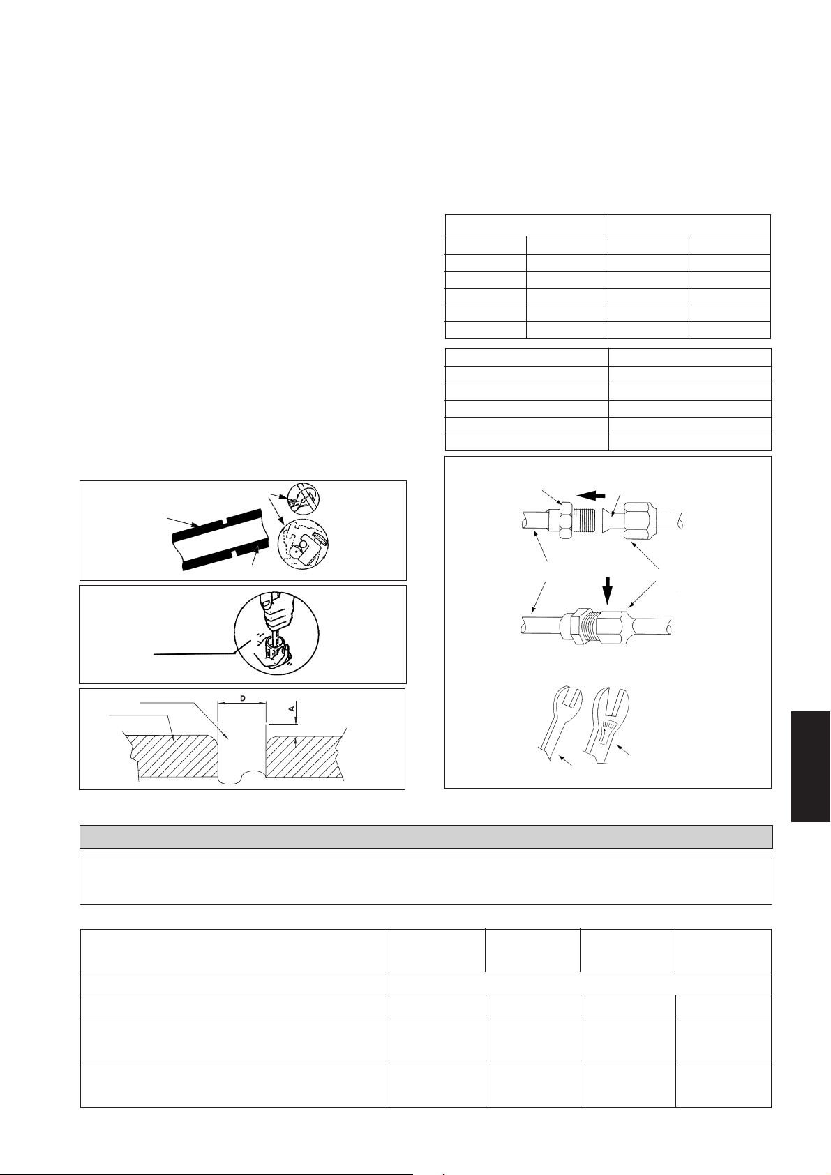
Проведение Трубопроводов И Соединение Муфтой
(Развальцовочнрй Гайкой)
Не используйте грязную или поврежденную трубную обвязку.
Если любая труба, испаритель или конденсатор были открыты
на 15 секунд или более, то откачайте воздух. В общем, не
снимайте пластиковое покрытие, резиновые пробки и
латунные гайки с клапанов, штуцеров, труб и радиаторов до
тех пор, пока он не готов для соединения.
Если требуется пайка, то удостоверьтесь, что газ азот
проходит через трубопровод и соединения, где проводится
пайка. Это позволит избежать формирование копоти на
внутренней стороне медных труб.
Режьте трубу постепенно, медленно подавая полотно резака.
Чрезмерное усилие и глубокий разрез вызовут деформацию
трубы и появление нежелательных выгибов.
Уберите заусенцы с краев среза трубы съемником как
показано на Pис. Т. Это позволит избежать неровности на
развальцовочных поверхностях, которые вызовут утечку газа.
Держите трубу в верхнем положении и съемник в нижнем
положении, чтобы предотвратить попадание металлических
частиц в трубу.
Вставьте штуцеры, установленные на соединяющие концы как
и комнатного блока и наружного блока, на медные трубы.
Точная длина трубы, выступающей из лицевой поверхности
матрицы, определена развальцовочным инструментом.
Надежно установите трубу в развальцовочной матрице.
Отцентрируйте положение развальцовочной матрицы и
развальцовочного пробойник, и хорошо закрепите пробойник.
Резка Медных Труб
Соединение Трубопроводов К Блокам
Отцентрируйте положение трубы и до конца затяните
штуцерную гайку усилием пальцев.
Затем, затяните штуцерную гайку динамометрическим
гаечным ключом до щелчка ключа.
При затягивании штуцерной гайки динамометрическим
гаечным ключом, удостоверьтесь, что затягивание происходит
в указанном стрелкой направлении.
Соединение трубопроводов системы охлаждения изолируется
полиуретаном (тип ARMAFLEX или подобный).
Ø Трубы, D A (мм)
Дюйм мм Империал Риджид
1/4" 6,35 1,3 0,7
3/8" 9,52 1,6 1,0
1/2" 12,70 1,9 1,3
5/8" 15,88 2,2 1,7
3/4" 19,05 2,5 2,0
Размер Трубы, мм (д) Крутящий Момент (Нм)
6,35 (1/4) 18
9,53 (3/8) 42
12,7 (1/2) 55
15,88 (5/8) 65
19,05 (3/4) 78
Cоединения Муфтой
Труба С Муфтой
1/4т
Медная Труба
Рис. Т
Уберите Заусенцы
Медная Труба
Обжимка
ЭЛЕКТРИЧЕСКАЯ СХЕМА
Удостоверьтесь, что цвета проводов на наружном блоке и маркировка
! Осторожно
Модель Только Охлаждения, CC 10 / 15 / 20 / 25 C
выводов соответствуют аналогичным на комнатном блоке.
Трубопровод Комнатного
Блока
Ключ
Штуцерная Гайка
Динамометрический
Гаечный Ключ
Русский
Комнатный Блок CC 10C CC 15C CC 20C CC 25C
Наружный Блок SL 10B SL 15B SL 20B SL 25B
Диапазон Напряжения**
220В – 240В /1Ф /50Гц + ! и 208В – 230В /1Ф /60Гц + !
Рекомендуемый Предохранитель* A 10 10 16 20
Сечение Шнура Сети* мм
2
1,5 1,5 2,5 2,5
Количество Проводников 33 3 3
Сечение Проводов Межсоединения* мм
2
1,5 1,5 2,5 2,5
Количество Проводников 33 3 3
6-5
Page 82

CC 10 / 15 / 20 / 25 C - SL 10 / 15 / 20 / 25 B
CC 28 / 30 C - SL 30 B
COMP
L
COMP
Колодка Соединителя
Наружного Блока
N
Колодка Соединителя
Комнатного Блока
N
!
!
Модель Только Охлаждения, CC 28/ 30 C
Комнатный Блок
Наружный Блок
Диапазон Напряжения**
Рекомендуемый Предохранитель*
Сечение Шнура Сети*
Количество Проводников
Сечение Проводов Межсоединения*
Количество Проводников
CC 28 / 30 C - SL 30 C
N
!
Шнур
Сети
220B – 240B / 1Ф / 50Гц + ! и 208B – 230B / 1Ф / 60Гц + !
A 25 25
2
мм
2
мм
Должен применяться двухполярный
выключатель с зазором контакта не менее
!
3 мм и автоматически выключатель, как зто
рекомендовано злектрической сxeмой
установки.
CC 28 / 30C
SL30B SL30C
4,0 4,0
33
2,5 2,5
34
COMP
Колодка
Соединителя
Наружного Блока
L
N
N
!
!
Должен применяться двухполярный
выключатель с зазором контакта не
!
менее 3 мм и автоматически
выключатель, как зто рекомендовано
злектрической сxeмой установки.
Модель Только Охлаждения, CC 38 / 40 / 50 /60 C
Комнатный Блок
Наружный Блок
Диапазон Напряжения
Рекомендуемый Предохранитель* (50/60Гц) A
Сечение Шнура Сети* (50/60Гц)
Количество Проводников
Сечение Проводов Межсоединения* (50/60Гц)
Количество Проводников
**
L
Колодка Соединителя
Комнатного Блока
N
!
S
R
COMP
L
N
Шнур Сети
CC38 / 40C CC50C CC60C
SL 40C SL 50C SL 60C и MSS60C
380B – 415B / 3Ф / 50Гц + N + ! и 208B–230B / 3Ф / 60Гц + N + !
10/20 16/25 16/25
2
мм
мм
2
1,5/2,5 2,5/4,0 2,5/4,0
55 5
1,5/1,5 1,5/1,5 1,5/1,5
44 4
!
ВАЖНО: * Эти данные даны только для справки. Они должны быть сравнены и выбраны для того, чтобы они отвечали
местным положениям и/или государственным стандартам. Они также зависят от типа установки и сечения
используемых проводников.
** Соответствующий диапазон напряжений следует сверять с данными, указанными на табличке, прикрепленной к
корпусу аппарата. Указанное значение ETL соответствует только источнику питания с частотой 60 Гц.
6-6
Page 83

CC 38 / 40 / 50 / 60 C - SL 40 / 50 / 60 C
COMP
L
N
Колодка Соединителя
Комнатного Блока
COMP
L
N
!
!
Должен применяться двухполярный
выключатель с зазором контакта не
менее 3 мм и автоматически выклю
!
чатель, как зто рекомендовано
злектрической сxeмой установки.
Модель Обогревательного, CC 10 / 15 / 20 / 25 CR
Комнатный Блок CC 10CR CC 15CR CC 20CR CC 25CR
Наружный Блок SL 10BR SL 15BR SL 20BR SL 25BR
Диапазон Напряжения**
Рекомендуемый Предохранитель* A 10 10 16 20
Сечение Шнура Сети* мм
Количество Проводников 33 3 3
Сечение Проводов Межсоединения* мм
Количество Проводников 55 5 5
Шнур Сети
220В – 240В / 1Ф / 50Гц + ! и 208В – 230В / 1Ф / 60Гц + !
2
2
1,5 1,5 2,5 2,5
1,5 1,5 2,5 2,5
Колодка Соединителя
Наружного Блока
R
S
T
N
!
CC 10 / 15 / 20 / 25 CR - SL 10 / 15 / 20 / 25 BR
ика Наружного Блока
4WV
OF
Колодка Соединителя
Комнатного Блока
COMP
L
N
N
!
!
Модель Обогревательного, CC 28 / 30 CR
Комнатный Блок
Наружный Блок
Диапазон Напряжения**
Рекомендуемый Предохранитель*
Сечение Шнура Сети*
Количество Проводников
Сечение Проводов Межсоединения*
Количество Проводников
Датчик Змеев
4WV
OF
Колодка Соединителя
COMP
Наружного Блока
N
!
Шнур Сети
Должен применяться двухполярный
выключатель с зазором контакта не
менее 3 мм и автоматически выклю
!
чатель, как зто рекомендовано
злектрической сxeмой установки.
CC 28/30 CR
SL 30BR SL 30CR
220B– 240B / 1Ф / 50Гц + ! и 208B – 230B / 1Ф / 60Гц + !
A 25 25
2
мм
мм
2
4,0 4,0
33
2,5 2,5
56
Русский
ВАЖНО: * Эти данные даны только для справки. Они должны быть сравнены и выбраны для того, чтобы они отвечали
местным положениям и/или государственным стандартам. Они также зависят от типа установки и сечения
используемых проводников.
** Соответствующий диапазон напряжений следует сверять с данными, указанными на табличке, прикрепленной к
корпусу аппарата. Указанное значение ETL соответствует только источнику питания с частотой 60 Гц.
6-7
Page 84

CC 28 / 30 CR - SL 30 BR
Должен применяться двухполярный
выключатель с зазором контакта не
!
менее 3 мм и автоматически выклю
чатель, как зто рекомендовано
злектрической сxeмой установки.
Колодка Соединителя
Наружного Блока
Датчик Змеевика Наружного Блока
A
4WV
OF
COMP
L
N
N
!
!
4WV
COMP
Шнур Сети
OF
N
!
Колодка
Соединителя
Комнатного
Блока
CC 28 / 30 CR - SL 30 CR
Датчик Змеевика Наружного Блока
A
4WV
OF
Колодка Соединителя
Наружного Блока
COMP
L
N
N
Должен применяться
двухполярный выключатель с
!
зазором контакта не менее
3 мм и автоматически выклю
чатель, как зто рекомендовано
злектрической сxeмой установки.
Модель Обогревательного, CC 38 / 40 / 50 / 60 CR
Комнатный Блок
!
!
CC 38 / 40CR CC 50CR CC 60CR
Наружный Блок
Диапазон Напряжения
Рекомендуемый Предохранитель* (50/60Гц)
Сечение Шнура Сети* (50/60Гц) мм
**
380B– 415B /3Ф /50Гц +N + ! и 208B – 230B /3Ф /60Гц + N + !
A 10/20 16/25 16/25
2
Шнур Сети
SL 40CR SL 50CR SL 60CR и MSS 60CR
1,5/2,5 2,5/4,0 2,5/4,0
A
4WV
OF
COMP
L
N
!
L
N
!
Колодка
Соединителя
Комнатного
Блока
Количество Проводников 55 5
Сечение Проводов Межсоединения
*
(50/60Гц)
мм
2
1,5/1,5 1,5/1,5 1,5/1,5
Количество Проводников 77 7
CC 38 / 40 / 50 / 60 CR - SL 40 / 50 / 60 CR
Датчик Змеевика Наружного Блока
!
ВАЖНО: *
A
4WV
Колодка Соединителя
Комнатного Блока
Должен применяться двухполярный
выключатель с зазором контакта не
OF
COMP
L
N
!
менее 3 мм и автоматически выклю
чатель, как зто рекомендовано
злектрической сxeмой установки.
Шнур Сети
Эти данные даны только для справки. Они должны быть сравнены и выбраны для того, чтобы они отвечали местным
положениям и/или государственным стандартам. Они также зависят от типа установки и сечения используемых проводников.
** Соответствующий диапазон напряжений следует сверять с данными, указанными на табличке, прикрепленной к корпусу
аппарата. Указанное значение ETL соответствует только источнику питания с частотой 60 Гц.
A
4WV
OF
COMP
L
Колодка
Соединителя
N
Наружного Блока
!
R
S
T
N
!
6-8
Page 85

! Осторожно
Удостоверьтесь, что цвета проводов на наружном блоке и маркировка выводов соответствуют
аналогичным на комнатном блоке.
СПЕЦИАЛЬНЫЕ МЕРЫ ПРЕДОСТОРОЖНОСТИ ПРИ ЭКСПЛУАТАЦИИ КОНДИЦИОНЕРА С ХЛАДАГЕНТОМ R410A
R410A - это новый гидрофторуглеродный хладагент, не
повреждающий озоновый слой. Рабочее давление этого
нового хладагента в 1,6 раз больше, чем рабочее давление
обычного хладагента (R22), поэтому очень важно соблюдать
правильный порядок установки и обслуживания
кондиционера.
• В кондиционерах, рассчитанных на использование
R410A, запрещается применять какие-либо другие
хладагенты.
• Для смазки компрессора R410A используется POE-
масло, которое отличается от минерального масла,
применяемого в компрессорах R22. Во время установки
или обслуживания необходимо принимать
дополнительные меры предосторожности, чтобы не
подвергать систему R410A слишком длительному
воздействию влажного воздуха. Оставшееся в
трубопроводах и компонентах масло POE может
поглощать влагу из воздуха.
• Во избежание неправильной заправки диаметр
сервисного патрубка на раструбном вентиле отличается
от диаметра соответствующего патрубка для R22.
ОСТОРОЖНО, КОГДА ИМЕТЕ ДЕЛО С ЕДИНИЦЕЙ R407C
• R407 - зеотропическая освежающая смесь, которая
имеет нулевой потенциал истощения озона, таким
образом соответствующая правилам Монреальского
Протокола. требует масла Полиэстера (POE) для смазки
ее компрессора. Ее освежающая способность и
выполнение работы схожи с охладителем R22.
• POE масло исползуется как смазка для компрессора
R407C, который отличается от минерального масла,
используемого для компрессора R22. В течение
установки или обслуживания, должна быть принята
дополнительная предосторожность, чтобы не
подвергнуть систему R407 долго сырому воздуху.
Остаточное масло POE в трубопроводе и компонентах
может поглощать влажность от воздуха.
• На охладитель R407C пыль влажности воздействует
быстрее по сравнению с R22, достовертесь, чтобы
временно закрытьконцы шланга трубки до установки.
• Используйте исключительно инструменты и материалы,
предназначенные для хладагента R410A. Инструменты
специально для R410A: распределительная гребенка,
заправочный шланг, манометр, детектор утечки газа,
развальцовочные инструменты, ключ с регулируемым
крутящим моментом, вакуумный насос и баллон для
хладагента.
• Так как в кондиционере на R410A используется более
высокое давление, чем в установках на R22, важно
правильно выбрать медные трубы. Запрещается
использовать медные трубы толщиной менее 0,8 мм,
даже если они есть в продаже.
• В случае утечки газообразного хладагента во время
выполнения работ по установке или обслуживанию
необходимо хорошо проветрить помещение. При
соприкосновении газообразного хладагента с огнем
возможно образование ядовитого газа.
• При установке или демонтаже кондиционера следите за
тем, чтобы в контуре хладагента не осталось воздуха
или влаги.
• дополнительная добавка масла компрессора не
разрешается.
• Никакой другой охладитель кроме R407C.
• Инструменты специально для R407 (не должны
использоваться для R22 или другого охладителя)
i) Разнообразный шаблон и шланг зарядки
ii) Датчик Утечки газа
iii) Освежающий цилиндр цилиндра/зарядки
iv) Вакуумый насос с адаптером
v) Инструменты Вспышки
vi) механизм восстановления Освежителя
• Сушилка фильтра должна быть установлена по жидкой
линии для всех кондиционеров R407C. Это должно
минимизировать загрязнение влажностью и грязью в
освежающей системе. Сушилка фильтра должна иметь
молекулярный тип решета. Для системы насоса высокой
температуры, установите двухстороннюю сушиилу
фильтра потока по жидкой линии.
ПРОДУВКА ТРУБОПРОВОДОВ ХЛАДАГЕНТА
Прочистите Трубопровод И Внутренний Модуль
За исключением внешнего модуля, который заправлен
хладагентом на заводе-изготовителе, внутренний модуль
и трубопроводы хладагента должны быть продуты,
поскольку воздух, содержащий влагу в системе
охлаждения, может вызвать сбои в работе компрессора.
Внешний модуль оборудован двумя 3-ходовыми
соединительными клапанами жидкости. Впускной клапан
большего размера, чем маленький на клапане жидкости.
Оба клапана имеют клапаном входа технического
обслуживания для подсоединения с манометром.
• Снимите колпачки с клапана и входа технического
обслуживания.
• Соедините центр распределительной коробки к
вакуумному насосу.
• Cоедините распределительную коробку к входу
технического обслуживания 3-ходового клапана.
• Включите вакуумный насос. Проверьте манометр
низкого давления, чтобы он показывал 0,9 бар. Время
откачки зависит от мощности отдельного типа
вакуумного насоса, но, в целом, полчаса.
6-9
• Закройте клапан распределительной коробки и
выключите вакуумный насос.
• На внешнем модуле, откройте клапан впуска и клапан
жидкости (против часовой стрелки) при помощи гаечного
ключа размером 4 мм для шестигранного винта.
• Модуль кондиционера готов к включению.
• Если показание близко к 0, то в системе охлаждения
должен быть откачен воздух (вакуумным насосом) и
вновь произведена заправка.
Штуцерная
Вход
Технического
Обслуживания
Трубопровод
Хладогента
Гайка
3 Ходовои Клапан
Внешнего Модуля
Гибкий Шланг
4 мм
Шестигранный
Гаечный ключ
Русский
Page 86
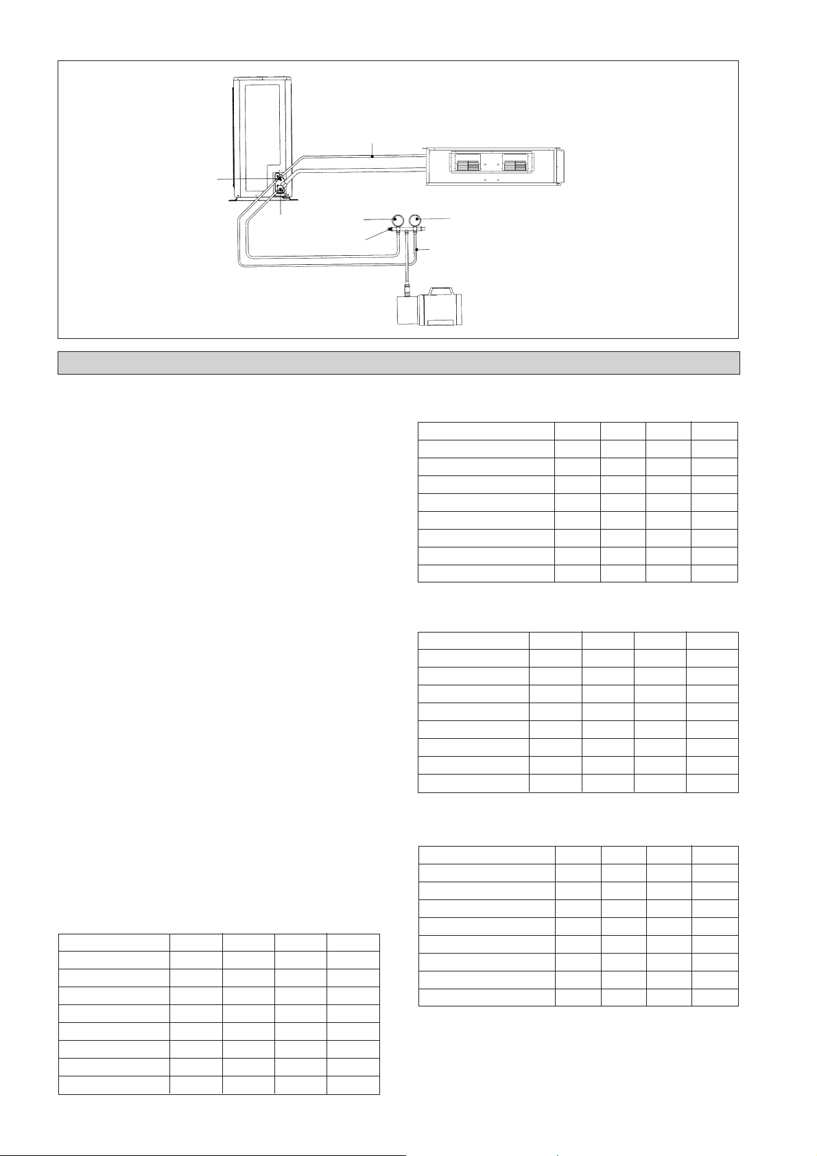
Наружный Блок
Трубопровод Хладогента
Клапан Жидкости
Манометр Низкого
Давления
Газовый Клапан
Распределительная Коробка
ДОПОЛНИТЕЛЬНАЯ ЗАПРАВКА
Хладагент заправлен заводом-изготовителем на
внешнем модуле. Если длина трубопроводов
меньше, чем 5 м, то в дозаправке после откачки
воздуха нет необходимости. Если длина
трубопроводов больше, чем 5 м, то используйте
клапан дозаправки, как показано в таблице внизу.
Дозаправка В Гр
Операция должна проводиться при помощи
газового цилиндра и обязательно точным
дозатором. Дозаправка во внешний модуль
проводится с помощью клапана впуска через вход
технического обслуживания.
• Снимите заглушку с клапана технического
обслуживания.
• Соедините распределительную коробку низкого
давления к входу технического обслуживания,
отцентрируйте для подсоединения к резервуару
цилиндра и закройте распределительную
коробку высокого давления (смотрите рисунок
внизу).
Прочистите полностью вспомогательный шланг
газом хладагента.
• Включите модуль кондиционера.
• Откройте газовый цилиндр и
распределительный клапан низкого давления.
• Когда требуемое количество хладагента
заправлено в модуль, то закройте
распределительную коробку низкого давления
и клапан газового цилиндра.
• Отсоедините манометр газовый цилиндр.
Установите колпачок входа технического
обслуживания обратно на его место.
Дозаправка В Гр (Модель Только Охлаждения) (R410A)
Модель 7 м 10 м 15 м 20 м
CC 10C 27 67 – –
CC 15C 27 67 – –
CC 20C 27 67 135 –
CC 25C 68 171 342 –
CC 28C / CC 30C 90 225 450 675
CC 38C / CC 40C 90 225 450 675
CC 50C 90 225 450 675
CC 60C 90 225 450 675
Комнатный Блок
Манометр Высокого Давления
Гибкий Шланг
Вакуумный Насос
Насоса Дозаправка В Гр (Модель Обогревательного)
(R410A)
Модель 7 м 10 м 15 м 20 м
CC 10CR 36 90 – –
CC 15CR 36 90 – –
CC 20CR 45 112 225 –
CC 25CR 90 225 450 –
CC 28CR / CC 30CR 90 225 450 675
CC 38CR / CC 40CR 90 225 450 675
CC 50CR 90 225 450 675
CC 60CR 90 225 450 675
Дозаправка В Гр (Модель Только Охлаждения)
(R22/R407C)
Модель 7 м 10 м 15 м 20 м
CC 10C 30 75 – –
CC 15C 30 75 – –
CC 20C 30 75 150 –
CC 25C 76 190 380 –
CC 28C / CC 30C 100 250 500 750
CC 38C / CC 40C 100 250 500 750
CC 50C 100 250 500 750
CC 60C 100 250 500 750
Насоса Дозаправка В Гр (Модель Обогревательного)
(R22/R407C)
Модель 7 м 10 м 15 м 20 м
CC 10CR 40 100 – –
CC 15CR 40 100 – –
CC 20CR 50 125 250 –
CC 25CR 100 250 500 –
CC 28CR / CC 30CR 100 250 500 750
CC 38CR / CC 40CR 100 250 500 750
CC 50CR 100 250 500 750
CC 60CR 100 250 500 750
6-10
Page 87

Проверьте Отсутствие Утечки Хладагента
Проверьте течеискателем хладагента отсутствие утечки газа на щтуцерном соединении внутреннем и
внешнего модулей.
Совет: После работы в течение некоторого времени, проверьте на наличие масляных пятен, при течи.
Наружный Блок
Трубопровод Хладагента
Клапан Жидкости
Манометр Низкого
Давления
Газовый Клапан
Распределительная Коробка
Резервуар Газа Хладагента
Комнатный Блок
Манометр Высокого Давления
Гибкий Шланг
СПЕЦИАЛЬНЫЕ МЕРЫ ПРЕДОСТОРОЖНОСТИ ПРИ ЗАПРАВКЕ КОНДИЦИОНЕРОВ СО
СПИРАЛЬНЫМИ КОМПРЕССОРАМИ COPELAND
Перечисленные здесь меры следует применять только при заправке спиральных компрессоров Copeland хладагентами
R22, R407C, R134A, R404A, R507 и R410A. Эти меры не применяются для поршневых компрессоров Copeland и для
спиральных компрессоров других производителей.
Спиральные компрессоры характеризуются очень высокой объемной производительностью, поэтому при работе они
быстро создают глубокий вакуум, если в системе недостаточно хладагента, или если хладагент добавляется слишком
медленно. Работа компрессора при низком давлении всасывания ведет к быстрому и очень значительному увеличению
температуры нагнетания. Во время этого процесса ухудшается качество смазывания спиралей, так как их смазка
происходит за счет масляного тумана в хладагенте. Недостаток смазки ведет к увеличению трения между боковыми
поверхностями и вершинами спиралей, что влечет за собой дополнительное выделение тепла. Суммарная тепловая
энергия, производимая при компрессии и выделяемая вследствие повышенного трения, сконцентрирована в маленьком
объеме области нагнетания, где температура может быстро увеличиваться до 300°C и выше. Такое чрезмерное повышение
температуры приводит к повреждению спиралей и подшипников менее, чем за одну минуту, особенно в мощных
компрессорах. Выход из строя может произойти в течение первых нескольких часов; повреждение, произошедшее в
процессе заправки на месте установки, может проявиться несколько позднее.
Другие типичные ошибки при заправке на месте установки включают заправку недостаточного или избыточного
количества хладагента, проникновение в систему влаги или воздуха и т.п. Со временем каждая из этих ошибок может
привести к выходу компрессора из строя.
Заправка на месте установки производится с использованием минимального количества оборудования. Для
удовлетворительного выполнения работ необходим следующий минимум оборудования:-
Набор ремонтных манометров Вакуумметр
Шланги Весы
Вакуумный насос Термометр
Необходимо заправлять количество хладагента, указанное производителем. Лицо, производящее установочные работы,
должно следовать рекомендациям производителя:
1. Процедура заправки - однофазные компрессоры
Откачать воздух из системы до давления 500 микрон ртутного столба (67 Па). Для уменьшения времени откачки
используйте короткие шланги большого диаметра и подсоединяйте их к сервисным патрубкам системы без
ограничений. Качество вакуума нельзя определить по времени - необходимо использовать надежный вакуумметр
(напр., электронный вакуумметр).
Перевернуть цилиндр с хладагентом вверх дном, продуть заправочный шланг и заправлять жидкостью через
заправочный патрубок жидкостной линии до прекращения потока хладагента или до заправки требуемой массы.
При необходимости дополнительной заправки запустить систему и медленно вводить жидкость со стороны всасывания
до заполнения системы.
Фирма Copeland рекомендует заправлять жидкий хладагент со стороны всасывания, КОНТРОЛИРУЯ процесс
заправки, до заполнения системы. Эта рекомендация недействительна для поршневых компрессоров, для которых
заправка жидким хладагентом со стороны всасывания может привести к серьезной поломке.
Внимательно следите за давлением всасывания и давлением нагнетания: в течение всего процесса заправки давление
всасывания не должно падать ниже 25 фунтов на кв. дюйм (1,7 бар).
Русский
6-11
Page 88

! Осторожно
• Если одновременно открыты вентиль цилиндра и вентиль “А” распределительной гребенки,
манометр распределительной гребенки будет показывать давление в цилиндре, а не давление
всасывания.
Существует много способов “контролируемой” заправки жидкого
хладагента со стороны всасывания:-
1. Использовать вентиль А на распределительной гребенке.
2. Использовать вентиль на цилиндре с хладагентом.
3. Заправлять через вентиль Шредера
4. Использовать шланг с депрессором вентиля Шредера
5. Заправлять со стороны всасывания на некотором расстоянии от
A
2. Процедура заправки - трехфазные компрессоры
Порядок заправки в основном такой же, как и для однофазных моделей, но компрессор при запуске может
работать в неправильном направлении. В этом случае необходимо поменять местами две фазы и запустить
его снова. Кратковременное вращение в противоположном направлении не причинит компрессору вреда.
Все компрессоры Specter (Модель: от ZR 90 до ZR 19M) оборудованы внутренними температурными
предохранителями, которые очень эффективно защищают от опасного повышения температуры нагнетания
при заправке. Предохранительный модуль при срабатывании выключает компрессор на 30 минут. Как правило,
нет необходимости ждать 30 минут, чтобы выполнить сброс модуля. После остывания компрессора сброс
модуля осуществляется путем отключения электропитания от управляющей схемы. Очень часто случается,
что мастер-наладчик не понимает причины срабатывания предохранителя и замыкает цепь в обход него с
помощью перемычки, после чего продолжает заправку системы, и убирает перемычку после завершения
заправки. Компрессор, возможно, и будет после этого работать, но с уверенностью можно сказать, что он
поврежден, и его преждевременный выход из строя неизбежен.
компрессора
6. Все вышеперечисленное
ОБЩАЯ ПРОВЕРКА
Удостоверьтесь в нижеследующем, в частности :-
1) Модуль установлен в надежном и крепком
положении.
2) Трубопроводы и соединения не дают течь после
заправки.
3) Провода соединены правильно.
Проверка дренажа:– налейте немного воды в левую
сторону дренажного лотка (дренаж расположен на
правой стороне модуля).
• Рабочие испытания
1) Проведите рабочие испытания после
проверки слива и наличия утечки газа.
2) Проследите нижеследующее:a) Установлена ли вилка плотно в
б) Слышны ли какие-нибудь ненормальные
в) Равномерен ли дренаж воды?
• Проверьте, что:
1) Вентилятор компрессора включился, с теплым
воздухом выходящим из компрессора.
2) Нагнетательный вентилятор включился.
3) Пульт дистанционного управления имеет задержку
3 минуты. Таким образом, требуется 3 минуты,
прежде чем наружный блок конденсации
включится.
УСЛОВИЯ СТАНДАРТНОЙ РАБОТЫ
Только охлаждение
Температура Ts °C / °F Th °C / °F
Минимальная комнатная
температура
Максимальная комнатная
температура
Минимальная наружная
температура
Максимальная наружная
температура
Тs : Шарик сухого термометра. Тh : Шарик смоченного термометра.
19,4 / 66,9 13,9 / 57,0
26,7 / 80,1 19,4 / 66,9
19,4 / 66,9 13,9 / 57,0
46 / 114,8 24 / 75,2
Обогревательный насос
Температура Ts °C / °F Th °C / °F
Минимальная комнатная
Максимальная комнатная
Минимальная наружная
Максимальная наружная
штепсельную розетку?
шумы из блока?
температура
температура
температура
температура
10 / 50 –
26,7 / 80,1 –
–8 / 17,6 -9 / 15,8
24 / 75,2 18 / 64,4
! Внимание
• Отключите сетевое питание перед обслуживанием блока кондиционера.
• НЕ вытаскивайте сетевой шнур, когда сеть ВКЛЮЧЕНА. Это может стать причиной резкой нагрузки
тока, что может привести к возгоранию.
6-12
Page 89

ФУНКЦИЯ БЕСПОРЯДОЧНОГО АВТОСТАРТА
Если произошло внезапное отключение тока при работающем блоке, то он автоматически возобновит тот же
операционный режим при восстановлении подачи питания. (Применимо только для блоков с этой функцией).
! Осторожно
Прежде чем отключить питание сети, установите переключатель ВКЛ/ВЫКЛ пульта дистанционного
управления в положение “ВЫКЛ” для предотвращения срабатывания аварийного выключателя блока.
Если это не будет проделано, то двигатель вентилятора начнет сразу же работать при восстановлении
питания, что представляет собой опасность для обслуживающего персонала и пользователя.
СЕРВИС И ТЕХНИЧЕСКОЕ ОБСЛУЖИВАНИЕ
Уэлы Обслуживания
Комнатный Воздушный
Фильтр
Комнатный Блок
Лоток И Труба Сбора Конденсата
Внутренний Вентилятор
Внутренний / Внешний
Радиатор
Процедуры Технического Обслуживания
1. Очистите от пыли фильтр пылесосом или вымойте его в теплой
воде (ниже 40°С) нейтральным моющим средством.
2. Хорошо прополоскайте и высушите фильтр перед установкой его
обратно в блок.
3. Не используйте бензиновые, легкоиспаряющиеся вещества или
химические средства для очистки фильтра.
1. Очистите от грязи или пыли решетку или панель, вытирая при
помощи мягкой ткани смоченной в теплой воде (ниже 40°С)
нейтральным моющим средством.
2. Не используйте бензиновые, легкоиспаряющиеся вещества или
химические средства для очистки комнатного блока.
1. Проверьте его чистоту и при необходимости почистите его.
1. Проверьте на наличие ненормального шума.
1. Проверьте и удалите загрязнение, скопившееся между ребрами.
2. Проверьте и удалите предметы, препятствующие впуску и
выпуску воздуха комнатного/наружного блока.
Не реже 2 раз в
неделю.
Чаще при
необходимости.
Не реже 2 раз в
неделю.
Чаще при
необходимости.
Раз в 3 месяца.
При необходимости.
Раз в месяц.
Раз в месяц.
Время
Источник Питания
Компрессор
Масло Компрессора
Масло Вентиляторного
Двигателя
1. Проверьте напряжение и силу тока комнатного и наружного блока.
2. Проверьте электрическую схему на отсутствие контактов, вызванных
слабым соединением, присутствием посторонних факторов и т.п. При
необходимости прикрепите провода на блок терминала.
1. Техническое обслуживание не требуется, если система
хладагента остается запломбированной.Однако, проверьте
отсутствие утечки хладагента во всех соединениях и фитингах.
1. Масло в компрессоре заправлено на предприятии-изготовителе. Если
система запломбирована, то нет необходимости в добавке масла.
1. Весь двигатель предварительно смазан и запломбирован на
предприятии.
Раз в 2 месяца.
Раз в 2 месяца.
Раз в 6 месяца.
Техническое обслуживание
не требуется.
Техническое обслуживание
не требуется.
! Осторожно
Не устанавливайте обогревательные приборы в непосредственной близости от кондиционеру. Это может
привести к расплавлению пластиковой панели или ее деформации в результате высокой температуры.
6-13
Русский
Page 90

МЕРЫ ПО УСТРАНЕНИЮ
При обнаружении сбоев в работе кондиционера, немедленно выключите питание сети
блока. Проверьте нижеследующие признаки неисправностей, причины и советы
простейших мер по устранению.
Неисправность
1. Компрессор не начинает функционирование
по прошествии 3 минут после включения
кондиционера.
2. Кондиционер не работает.
3. Очень незначительный поток воздуха.
4. Дисплей пульта дистанционного управления
не дает показаний.
Причины
- Защита от частого включения. Подождите от 3
до 4 минут, чтобы компрессор включился.
- Отсутствие сетевого питания или требуется
замена предохранителя.
- Вилка не вставлена.
- Существует вероятность того, что таймер
задержки установлен неправильно.
- Если неисправность не устранена после всех
этих проверок, пожалуйста, свяжитесь с
персоналом, установившего кондиционер.
- Воздушный фильтр загрязнен.
- Двери или окна открыты.
- Забился впуск и выпуск воздуха.
- Установленная температура недостаточно высока.
- Батарея села.
- Батареи установлены неправильно.
5. При выпуске воздуха имеется неприятный
запах.
6. Конденсат на передней решетке комнатного
блока.
7. Вода выливается из кондиционера.
8. Шипящий звук воздуха из кондиционера во
время работы.
- Неприятный запах может быть вызван сигаретами,
частицами дыма, парфюмерии и т.п., которые могли
осесть на змеевике.
- Это вызвано влагой в воздухе после
продолжительного времени функционирования.
- Установленная температура слишком низка,
увеличьте установленную температуру и
установите скорость вентилятора на высокую.
- Проверьте отсутствие конденсата.
- Попадание хладагента на испарительный
змеевик.
Если неисправность неустранима, пожалуйста, обращайтесь к Вашему местному
дилеру / специалисту.
6-14
Page 91

Page 92

• In the event that there is any conflict in the interpretation of this manual and any translation of the same in any language,
the English version of this manual shall prevail.
• The manufacturer reserves the right to revise any of the specification and design contain herein at any time without prior
notification.
• En cas de désaccord sur l’interprétation de ce manuel ou une de ses traductions, la version anglaise fera autorité.
• Le fabriquant se réserve le droit de modifier à tout moment et sans préavis la conception et les caractéristiques techniques
des appareils présentés dans ce manuel.
• Im Falle einer widersprüchlichen Auslegung der vorliegenden Anleitung bzw. einer ihrer Übersetzungen gilt die Ausführung
in Englisch.
• Änderungen von Design und technischen Merkmalen der in dieser Anleitung beschriebenen Geräte bleiben dem Hersteller
jederzeit vorbehalten.
• Nel caso ci fossero conflitti nell’interpretazione di questo manuale o delle sue stesse traduzioni in altre lingue, la versione
in lingua inglese prevale.
• Il fabbricante mantiene il diritto di cambiare qualsiasi specificazione e disegno contenuti qui senza precedente notifica.
• En caso de conflicto en la interpretación de este manual, y en su traducción a cualquier idioma, prevalecerá la versión
inglesa.
• El fabricante se reserva el derecho a modificar cualquiera de las especificaciones y diseños contenidos en el presente
manual en cualquier momento y sin notificación previa.
• В случае противоречия перевода данного руководства с другими переводами одного и того же текста,
английский вариант рассматривается как приоритетный.
• Завод-изготовитель оставляет за собой право изменять характеристики и конструкцию в любое время
без предварительного уведомления.
OYL MANUFACTURING COMPANY SDN. BHD.
JALAN PENGAPIT 15/19, P.O. BOX 7072, 40702 SHAH ALAM, SELANGOR DARUL EHSAN, MALAYSIA.
Page 93

VOd²« VO²
IM-CCC-0501-ACSON :
“«dÞ
WOHIÝ ¡«u¼ WHOJ
wH<« ŸuM« sË s¹√eł s
qKð®
C
©
nI« wH
Page 94

Page 95

œUFÐ_«Ë wDOD²« rÝd«œUFÐ_«Ë wDOD²« rÝd«
œUFÐ_«Ë wDOD²« rÝd«
œUFÐ_«Ë wDOD²« rÝd«œUFÐ_«Ë wDOD²« rÝd«
qKð® WOKš«b« …bŠu« qKð® WOKš«b« …bŠu«
qKð® WOKš«b« …bŠu«CC©
qKð® WOKš«b« …bŠu« qKð® WOKš«b« …bŠu«
I
J
K
L
©WuЮØ3 d²LOK*UÐ w¼ œUFÐ_« lOLł©WuЮØ3 d²LOK*UÐ w¼ œUFÐ_« lOLł
©WuЮØ3 d²LOK*UÐ w¼ œUFÐ_« lOLł
©WuЮØ3 d²LOK*UÐ w¼ œUFÐ_« lOLł©WuЮØ3 d²LOK*UÐ w¼ œUFÐ_« lOLł
B
C
D
H
A
E
MN
F
ABCDEFGHIJKLMN O
317417026621076572261411351225211232212.8114
(1.2)(29.2)(27.6)(26.1)(0.4)(30.1)(2.8)(10.3)(16.2)(13.8)(8.9)(8.3)(9.1)(8.4)(4.5)
318818428021090572261411351225211232212.8114
(1.2)(34.7)(33.1)(31.6)(0.4)(35.6)(2.8)(10.3)(16.2)(13.8)(8.9)(8.3)(9.1)(8.4)(4.5)
311041100296210106572261411351225211232212.8114
(1.2)(41.0)(39.4)(37.9)(0.4)(41.9)(2.8)(10.3)(16.2)(13.8)(8.9)(8.3)(9.1)(8.4)(4.5)
3111761137109710120072261411351225211232212.8114
(1.2)(46.3)(44.8)(43.2)(0.4)(47.2)(2.8)(10.3)(16.2)(13.8)(8.9)(8.3)(9.1)(8.4)(4.5)
“«dÞ“«dÞ
“«dÞ
“«dÞ“«dÞ
CC 10 C/CR
CC 15 C/CR
CC 20 C/CR
CC 25 C/CR
O
G
©WuЮØ3 d²LOK*UÐ w¼ œUFÐ_« lOLł©WuЮØ3 d²LOK*UÐ w¼ œUFÐ_« lOLł
©WuЮØ3 d²LOK*UÐ w¼ œUFÐ_« lOLł
©WuЮØ3 d²LOK*UÐ w¼ œUFÐ_« lOLł©WuЮØ3 d²LOK*UÐ w¼ œUFÐ_« lOLł
61.0 (2.40)
24.5 (0.96)
E
K K
L
AA
40.0
B
C
D
MN
(1.57)
qKð® WOKš«b« …bŠu« qKð® WOKš«b« …bŠu«
qKð® WOKš«b« …bŠu«CC©
qKð® WOKš«b« …bŠu« qKð® WOKš«b« …bŠu«
61,0 (2,40)
E
24.5 (0.96)
15.0
(0.59)
40.0
15,0 (0,59)
474.0 (18.66)
142.0 (5.59) 143.0 (5.63)
39.0 (1.54)
40.0 (1.57)
49.0 (1.93)
40.0
(1.57)
I
F
156.0
(6.14)
G
H
40.0 (1.57)
26.0 (1.12)
90.5
(3.56)
J
187.5 (7.38)
100.0
(3.94)
41.0 (1.61)
“«dÞ“«dÞ
“«dÞ
“«dÞ“«dÞ
ABCDEFGHIJKLMN
371.71007959920410,029560033912121364.0100,0239214.0
(14.6)(39.6)(37.8)(36.2)(16.1)(11.6)(23.6)(13.3)(4.8)(8.4)(2.5)(3.9)(9.4)(8.4)
CC 28C/CR
359999956917408.537854125617330670.5160.5248220.0
(14.1)(39.3)(37.6)(36.1)(16.1)(14.9)(21.3)(10.1)(6.8)(12.0)(2.8)(6.3)(9.8)(8.7)
CC 30C/CR
371.2131212641225562.5315638401183233217.0169.2251237.8
(14.6)(51.7)(49.8)(48.2)(22.1)(12.4)(25.1)(15.8)(7.2)(9.2)(8.5)(6.7)(9.9)(9.4)
CC 38C/CR
359111510721033466.5378541256173306128.5160.5248220.0
(14.1)(43.9)(42.2)(40.7)(18.4)(14.9)(21.3)(10.1)(6.8)(12.0)(5.1)(6.3)(9.8)(8.7)
CC 40C/CR
359136913261287593.5378541256173306255.5160.5248220.0
(14.1)(53.9)(52.2)(50.7)(23.4)(14.9)(21.3)(10.1)(6.8)(12.0)(10.1)(6.3)(9.8)(8.7)
CC 50C/CR
359156915261487693.5378541256173306355.5160,5248220.0
(14.1)(53.9)(60.1)(58.5)(27.3)(14.9)(21.3)(10.1)(6.8)(12.0)(14.0)(6.3)(9.8)(8.7)
CC 60C/CR
i
Page 96

qKð® WOKš«b« …bŠu« qKð® WOKš«b« …bŠu«
qKð® WOKš«b« …bŠu«SL-B©
qKð® WOKš«b« …bŠu« qKð® WOKš«b« …bŠu«
©WuЮØ3 d²LOK*UÐ w¼ œUFÐ_« lOLł©WuЮØ3 d²LOK*UÐ w¼ œUFÐ_« lOLł
©WuЮØ3 d²LOK*UÐ w¼ œUFÐ_« lOLł
©WuЮØ3 d²LOK*UÐ w¼ œUFÐ_« lOLł©WuЮØ3 d²LOK*UÐ w¼ œUFÐ_« lOLł
C
5 (0.2)
A
15 (0.6)
39 (1.5)
R
N
M
15 (0.6)
39 (1.5)
E
20 (0.8)
P
Q
840 (33.1)
D
P
2.5 (0.1)
F
20 (0.8)
5 (0.2)
B
C
160 (6.3)
7404942702662334744755651669234831812948268.5
(29.1)(19.4)(10.6)(10.5)(9.2)(18.7)(1.9)(2.2)(2.6)(6.5)(3.6)(13.7)(12.5)(5.1)(19.0)(2.7)
H
(2.6)
L
G
141 (5.6)
J
K
65
20 (0.8)
œUFÐ_«œUFÐ_«
œUFÐ_«ABCDEFGHJKLMNPQR
œUFÐ_«œUFÐ_«
07B / 07BR
10B / 10BR
15B / 15BR
©WuЮØ3 d²LOK*UÐ w¼ œUFÐ_« lOLł©WuЮØ3 d²LOK*UÐ w¼ œUFÐ_« lOLł
©WuЮØ3 d²LOK*UÐ w¼ œUFÐ_« lOLł
©WuЮØ3 d²LOK*UÐ w¼ œUFÐ_« lOLł©WuЮØ3 d²LOK*UÐ w¼ œUFÐ_« lOLł
(0.1)
(0.7)
84064633029730962641857517710640837812459278.5
C
G
IJ
(33.1)(25.4)(13.0)(11.7)
H
(12.2)
(24.6)(1.6)(3.3)(3.0)(7.0)(4.2)(16.1)(14.9)(4.9)(23.3)(3.1)
qKð® WOKš«b« …bŠu« qKð® WOKš«b« …bŠu«
qKð® WOKš«b« …bŠu«SL / 5SL-C©
qKð® WOKš«b« …bŠu« qKð® WOKš«b« …bŠu«
L
O
3
B
19
KL
A
D
(1.2)
N
M
CN
30
F
E
65
(2.6)
80
(3.1)
20B / 20BR
25B / 25BR
30B / 30BR
œUFÐ_«œUFÐ_«
œUFÐ_«ABCDEFGHIJKLMNO
œUFÐ_«œUFÐ_«
10 / 15 C /CR
70052125048517536959386684411301111518
(27.5)(20.5)(9.8)(19.1)(6.8)(1.4)(3.7)(3.6)(3.3)(2.6)(17.3)(5.1)(4.3)(0.5)(0.7)
ii
Page 97

qKð® WOKš«b« …bŠu« qKð® WOKš«b« …bŠu«
qKð® WOKš«b« …bŠu«SLC©
qKð® WOKš«b« …bŠu« qKð® WOKš«b« …bŠu«
A
P
L
K
M
D
F
B
E
N
C
G
J
©WuЮØ3 d²LOK*UÐ w¼ œUFÐ_« lOLł©WuЮØ3 d²LOK*UÐ w¼ œUFÐ_« lOLł
©WuЮØ3 d²LOK*UÐ w¼ œUFÐ_« lOLł
©WuЮØ3 d²LOK*UÐ w¼ œUFÐ_« lOLł©WuЮØ3 d²LOK*UÐ w¼ œUFÐ_« lOLł
H
SLABCDEFGHJKLMNP
180.0 (7.09)
524.0 (20.63)
11.0 (0.43)
940.0 (37.00)
11.0 (0.43)
180.0 (7.09)
10308504003904148277219691488448141,5746,582
(40.6)(33.5)(15.7)(15.4)(16.3)(32.6)(2.8)(7.7)(3.6)(19.2)(17.6)(5.6)(29.4)(3.2)
30C /40C /50C /60C
® WOKš«b« …bŠu«® WOKš«b« …bŠu«
® WOKš«b« …bŠu«MSS 60C©
® WOKš«b« …bŠu«® WOKš«b« …bŠu«
500.0 (19.69)1300.0 (51.18)
165.0 (6.50)
65.0
(2.56)
iii
©WuЮØ3 d²LOK*UÐ w¼ œUFÐ_« lOLł©WuЮØ3 d²LOK*UÐ w¼ œUFÐ_« lOLł
©WuЮØ3 d²LOK*UÐ w¼ œUFÐ_« lOLł
©WuЮØ3 d²LOK*UÐ w¼ œUFÐ_« lOLł©WuЮØ3 d²LOK*UÐ w¼ œUFÐ_« lOLł
946.0 (37.24)
Page 98

ÆÕËd'« dÞU V³ð w²«Ë WMU l«u w WH²K `DÝ« Ë …œUŠ UUŠ
ÆsU_« ÁcNÐ „UJ²Šô« s VM&
tO³MðtO³Mð
tO³Mð !
tO³MðtO³Mð
iv
Page 99

wÐdŽwÐdŽ
wÐdŽwÐdŽ
wÐdŽ
VOd²« VO²
Æ¡«uN« WHOJ …bŠu ÊuQ*«Ë bO'« ÍœUF« qOGA²« ÊULC VOd²« ‚dDÐ VO²J« «c¼ „œËe¹
ÆpðU³KD² rzö¹ wJ ’Uš j³{ ¡«dł« Í—ËdC« s ÊuJ¹ b
Æq³I²*« w WFł«dLK tÐ ÿUH²Šô«Ë W¹UMFÐ «c¼ ULOKF²« VO² …¡«d vłd¹ ¨¡«uN« WHOJ ‰ULF²Ý« q³
wH<« ŸuM« sË s¹√eł s WOHIÝ ¡«u¼ WHOJ
“«dÞ
W¾b²« a{ …bŠË
CC10CR / ACC10CR
SL10BR / ALC10BR
SL10CR / ALC10CR
4SL10BR / A4LC10BR
5SL10CR / A5LC10CR
CC15CR / ACC15CR
SL15BR / ALC15BR
SL15CR / ALC15CR
4SL15BR / A4LC15BR
5SL15CR / A5LC15CR
CC20CR / ACC20CR
SL20BR / ALC20BR
4SL20BR / A4LC20BR
5SL20BR / A5LC20BR
CC25CR / ACC25CR
SL25BR / ALC25BR
4SL25BR / A4LC25BR
5SL25BR / A5LC25BR
CC28CR / ACC28CR
SL30BR / ALC30BR
SL30CR / ALC30CR
4SL30CR / A4LC30CR
5SL30CR / A5LC30CR
CC30CR / ACC30CR
SL30BR / ALC30BR
SL30CR / ALC30CR
4SL30CR / A4LC30CR
5SL30CR / A5LC30CR
CC38CR / ACC38CR
SL40CR / ALC40CR
4SL40CR / A4LC40CR
5SL40CR / A5LC40CR
CC40CR / ACC40CR
SL40CR / ALC40CR
4SL40CR / A4LC40CR
5SL40CR / A5LC40CR
CC50CR / ACC50CR
SL50CR / ALC50CR
4SL50CR / A4LC50CR
5SL50CR / A5LC50CR
CC60CR / ACC60CR
SL60CR / ALC60CR
4SL60CR / A4LC60CR
5SL60CR / A5LC60CR
MSS60CR / AMC60CR
b¹d³²« …bŠË
CC10C / ACC10C
SL10B / ALC10B
SL10C / ALC10C
4SL10B / A4LC10B
5SL10C / A5LC10C
CC15C / ACC15C
SL15B / ALC15B
SL15C / ALC15C
4SL15B / A4LC15B
5SL15C / A5LC15C
CC20C / ACC20C
SL20B / ALC20B
4SL20B / A4LC20B
5SL20B / A5LC20B
CC25C / ACC25C
SL25B / ALC25B
4SL25B / A4LC25B
5SL25B / A5LC25B
CC28C / ACC28C
SL30B / ALC30B
SL30C / ALC30C
4SL30C / A4LC30C
5SL30C / A5LC30C
CC30C / ACC30C
SL30B / ALC30B
SL30C / ALC30C
4SL30C / A4LC30C
5SL30C / A5LC30C
CC38C / ACC38C
SL40C / ALC40C
4SL40C / A4LC40C
5SL40C / A5LC40C
CC40C / ACC40C
SL40C / ALC40C
4SL40C / A4LC40C
5SL40C / A5LC40C
CC50C / ACC50C
SL50C / ALC50C
4SL50C / A4LC50C
5SL50C / A5LC50C
CC60C / ACC60C
SL60C / ALC60C
4SL60C / A4LC60C
5SL60C / A5LC60C
MSS60C / AMC60C
IM-CCC-0501(3)-Acson
Part No.: A08019025456
±
 Loading...