

Page 1

Ceiling Convertible
Split Systems
ACM - E- 2007
ACM 15 E/ER
ACM 20 E/ER
ACM 25 E/ER
ACM 28 E/ER
A5CM 15 E/ER
A5CM 20 E/ER
A5CM 25 E/ER
A5CM 28 E/ER
Models:
Page 2

TABLE OF CONTENTS
1. NOMENECLATURE ................................................................................................... 1
2. PRODUCT LINE-UP .................................................................................................. 3
3. FEATURES ................................................................................................................ 6
4. APPLICATION INFORMATION
- OPERATING RANGE .......................................................................................... 7
- REFRIGERANT CIRCUIT DIAGRAMS ............................................................... 8
- CONTROLLERS ................................................................................................ 14
- INSTALLATION .................................................................................................. 18
5. ENGINEERING AND PHYSICAL DATA
- GENERAL DATA ................................................................................................ 31
- COMPONENTS DATA........................................................................................ 45
- SAFETY DEVICES ............................................................................................. 59
6. PERFORMANCE DATA ............................................................................................ 63
- PERFORMANCE TABLES ................................................................................ 67
7. DIMENSIONAL DATA ............................................................................................... 87
8. ELECTRICAL DATA.................................................................................................. 89
9. WIRING DIAGRAMS................................................................................................. 97
10. SERVICING AND MAINTENANCE........................................................................ 108
11. TROUBLESHOOTING ........................................................................................... 110
12. EXPLODED VIEW & PARTS LIST ........................................................................ 115
Page 3

Indoor
Others
A : First issue
Other Specifications
I : Ionizer Generator
N : Non Thermal Plasma
Controller
Specifications
G : Wireless handset
S : SLM3
N : Netware III
Market Region
C : Export with CE mark
Electrical
1. NOMENCLATURE
A : 220 - 240V/1Ph/50Hz
A CM 20
5
E
R
G IA C A-
Model Type
R : heatpump
Omitted if Cooling Only
Series
E : E series
Capacity
20 : 20,000 Btu/h
Model Name
CM : Ceiling Convertible
Refrigerant
5 : R410A
Omitted if R22 model
Brand
A : ACSON
1
Page 4

Outdoor
Others
A : First issue
Specifications Variation
O : Standard unit I : Gold Fin
B : With Contactor L : Long Piping Unit
G : Low Ambient Unit S : With H/L Pressure Switch
H : High ambient unit X :Oxygen Unit
Compressor
P : Matsushita Rotary T : Toshiba Rotary
M :Mitsubishi Rotary
Market Region
C : Export with CE marking
E : Export without marking
U : ETL Spec.
Electrical
A : 220 - 240V/1Ph/50Hz
A LC 20 C R
5 P OA C A-
Model Type
R : heatpump
Omitted if Cooling
Series
C : C series
Capacity
20 : 20,000 Btu/h
Model Name
LC : Single Split Condensing unit
Refrigerant
5 : R410A
Omitted if R22 model
Brand
A : ACSON
2
Page 5

2. PRODUCT LINE UP
INDOOR UNIT
ACM-E SERIES PRODUCT LINE UP
Classification
ACM
15E ACGIA X X X X X X
ACGIAX XX XX X
20E
ACGNAX XXXXX
ACGIAX XX XX X
25E
ACGNAX XXXXX
Cooling ModelHeat Pump Model
ACGIAX XX XX X
28E
ACGNA X X X X X X
15ERACGIAX XX XX X
ACGIAX XX XX X
20ER
ACGNAX XXXXX
ACGIAX XX XX X
25ER
ACGNAX XXXXX
ACGIAX XX XX X
28ER
ACGNAX XXXXX
A5CM-E SERIES PRODUCT LINE UP
Handset
Control Module
Nomenclature
L2
SLM3
Netware III
G12 Handset
Classification
Fin
Marking
NTP
Ionizer
CE Mark
W/out Marking
Hydrophilic (SLIT)
Control
Refrigerant
Cap. Tube
W/out Cap. Tube
Handset
NONMENCLATURE
Control Module
L2
SLM3
Netware III
G12 Handset
A5CM
15E ACGIA X X X X X X
ACGI A X X X X X X
20E
ACGNAX XXXXX
ACGI A X X X X X X
25E
ACGNAX XXXXX
Cooling ModelHeat Pump Model
ACGI A X X X X X X
28E
ACGNAX XXXXX
15ER ACGIA X X X X X X
ACGI A X X X X X X
20ER
ACGNAX XXXXX
ACGI A X X X X X X
25ER
ACGNAX XXXXX
ACGI A X X X X X X
28ER
ACGNAX XXXXX
Fin
Marking
NTP
Negative Ionizer
CE Mark
W/out Marking
Hydrophilic (SLIT)
3
Cap. Tube
Control
Refrigerant
W/out Cap.Tube
Page 6

4
OUTDOOR UNIT
ALC-C SERIES PRODUCT LINE UP
Grille
Cap. Tube
TXV
Gold Fin
High Ambient Kit
Low Ambient Kit
Contactor
High Pressure Switch
Low Pressure Switch
Nantong Press. SW
Phase Sequencer
Drain Elbow
Copeland Scroll Comp.
Rotary
CE Marking
ETL
ACPO D X X X
ACPID X X X X
ACPBD X X X X
ACPYD X X X X X
ACPO D
XXX
ACPID
XX XX
ACPO D
XXX
ACPID
XX XX
ACPO D
XXX
ACPID
XX XX
ACPOA
XX
ACPIA
XXX
AFGE XXXX X X
AFGF X X X X X X X
AFGG X X X X X X X
FFGE XXXXX X X
FFGG X XXXXX X X
ACPO B X X X
ACPIB X X X X
ACPO D X X X
ACPID X X X X
ACPO D
XXX
ACPID
XX XX
ACPO D
XXX
ACPID
XX XX
ACPOA
XXX
ACPIA
XX XX
AFFB XX XX X XX X
AFFCXXXXXXXXX
AFFD XXX XX X XX X
FFFB XX XX XXXX X
FFFD XXX XX XXXX X
25C
28C
15CR
18CR
30CR
28CR
20CR
Safety Devices
Classification
Marking
Refrigerant
Ctrl + Fin
Compressor
25CR
Special
30C
Nomenclature
ALC
18C
20C
Cooling Model
15C
Heat Pump Model
Page 7

5
OUTDOOR UNIT
A5LC-C SERIES PRODUCT LINE UP
Grille
Cap. Tube
TXV
Gold Fin
High Ambient Kit
Low Ambient Kit
Contactor
High Pressure Switch
Low Pressure Switch
Nantong Press. SW
Phase Sequencer
Drain Elbow
Copeland Scroll Comp.
Rotary
CE Marking
ETL
15C ACPOC X X X
ACPI A X X X X
ACPOA X X X
FCPOC X X X X
FCPIC X X X X X
ACPI A X X X X
ACPOA X X X
FCPOC X X X X
PCPIC X X X X X
ACPOA X X X
ACPI A X X X X
FCPOA X X X X
FCPIA X X X X X
ACCOAXX XXX X X
ACCIA XXX XXX X X
FCCOAXX XXXXX X X
15CR ACPOC X X X
ACPI A X X X X
ACPOC X X X
FCPOC X X X X X
FCPIC X X X X X X
ACPI A X X X X
ACPOC X X X
FCPOC X X X X X
FCPIC X X X X X X
ACPOA X X X
ACPI A X X X X
FCPOA X X X X X
FCPIA X X X X X X
ACCOAXX XXX X X
ACCGAXXX XXX X X
FCCOAXX XXXXXXX X
FCCGAXXX XXX XXX X
20CR
25CR
28CR
Heat Pump Model
35CR
Classification
Marking
Refrigerant
Ctrl + Fin
Special
Compressor
Safety Devices
Nomenclature
A5LC
Cooling Model
20C
25C
28C
35C
Page 8

3. FEATURES
Ceiling And Floor Installation Option
The unit is uniquely designed with the option to install either below the ceiling or mounted at low wall position
without any modification needed. Furthermore, the unit is design adds a touch of elegance to suit any interior
design requirement
Excellent Air Distribution
The louver with automatic air swing function fully optimize the room comfort by enables the air flow to be
evenly distributed into the room from the front discharge area.
Negative Ion Generator
ACSON emphasis on provide indoor air quality solution. Therefore, the negative ionizer technology is being
brought in as an essential part of the unit. The negative ion generator increases the amount of negative ion in
the air-conditioning area, creating a refreshing and healthy living environment.
Easy Installation
The ceiling convertible fan coil unit is easily installed with a very economical and space saving installation. No
need renovation on wall or ceiling for installation. This easy to install and ready to operate unit ensure rapid
and low installation cost.
Magnificent Serviceability
The blower, fan motor assembly and electrical parts can be inspected and air filter can be accessed by pulling
down the air intake grille. During servicing or repairing, only the bottom panel needs to be removed in order to
access the fan motor, blower, control box piping connection and drain pan.
Wireless Remote Controller
The standard unit comes with a simple, user friendly and stylish wireless controller. The G12 controller offers
many features:
• The compact LCD transmitter is able to operate the indoor unit within 9 meters of distance.
• Fan speed can be set at low/medium/high or automatic.
• Sleep mode auto control will gradually increase or decrease the set temperature to provide a comfort-
able surrounding for sleeping.
• The real time timer allows the unit to be switched ON and OFF automatically based on user settings.
• Ionizer or non-thermal plasma is available to create better air quality.
• Turbo mode function is available to enables the required set temperature to be achieved in a short time.
• Personalized Setting allows user to preset and store 2 groups of personal settings (including timer
setting) in the handset.
Auto Random Restart
Auto random restart function allows the unit to automatic restart as the last setting condition when the power
supply is resumed after power failure. However, the compressor will restart randomly if more than one unit is
installed and sharing the same phase of power.
Self Diagnosis
The microprocessor provides the possibility to detect and diagnose any fault or malfunction that occurs in the
system. The error will be reflected by the blinking of the LED lights.
6
Page 9

4. APPLICATION INFORMATION
Operating Range
Ensure the operating temperature is in allowable range.
Cooling only
Heatpump
54
46
35
19
Outdoor temp. (°CDB)
-5
18
6
High ambient
unit
Standard
point
Low ambient kit
15
24
Indoor temp. (°CWB)
Heating
Standard
point
Caution :
The use of your air conditioner
outside the range of working
temperature and humidity can
result in serious failure.
Cooling
54
46
35
19
High ambient
un t
Standard
point
Note :
Outdoor temp. (°CWB)
-9
15 21
27
Indoor temp. (°CDB)
Standard operating range.
With High ambient unit. (Optional item)
Please refer to local dealer for unit of this specification.
With Low ambient kit. (Optional item)
Please refer to local dealer for unit of this specification.
7
Outdoor temp. (°CDB)
-5
Low ambient kit
15
24
Indoor temp. (°CWB)
Page 10

Refrigerant Circuit Diagrams
MODEL : ACM / A5CM 15E - ALC / A5LC 15C ACM 20E - ALC 18C
ACM / A5CM 20E - ALC / A5LC 20C A5CM 25E - A5LC 25C
MODEL : ACM 25E - ALC 25C
A5CM 28E - A5LC 28C
8
Page 11

MODEL : ACM 28E - ALC 28C
MODEL : ACM 28E - ALC 30C
9
Page 12

MODEL : A5CM 28E - A5LC 35C
MODEL : ACM / A5CM 15ER - ALC / A5LC 15CR
10
Page 13

MODEL : ACM / A5CM 20ER - ALC / A5LC 20CR
A5CM 25ER - A5LC 25CR
MODEL : ACM 25ER - ALC 25CR ACM 28ER - ALC 28CR
11
Page 14

MODEL : A5CM 28ER - A5LC 28CR
MODEL : ACM 28ER - ALC 30CR
12
Page 15

MODEL : A5CM 28ER - A5LC 35CR
13
Page 16

Controllers
G12 Remote Controller
Temperature Setting
• To set the desired room
temperature, press the button to
increase or decrease the set
temperature.
• The temperature setting range is
from 16°C to 30°C
• Press both buttons simultaneously
to toggle the temperature setting
between °C and °F
On/Off Button
• Press Once to start the air
conditioner
• Press again to stop the unit
ON Timer Setting
• Press the SET button will activate
the on timer function.
• Set the desired on time by pressing
the SET button continuously.
• Press the CLR button to cancel the
off timer setting
Personalised Setting
• Press and hold the button for 3s to
initiate personalized setting.
• Set the individual setting e.g.
MODE, SET TEMP or FAN SPEED
and leave for 4s to save
• 2 groups of settings are allowed to
stored in the handset
OFF Timer Setting
• Press the SET button will activate
the off timer function.
• Set the desired off time by
pressing the SET button
continuously.
• Press the CLR button to cancel the
off timer setting
Clock Time Setting
• Press button + or - to increase or
decrease the clock time.
Fan Speed Selection
• Press the button until the desired
fan speed is achieved.
Turbo Mode
• Press the TURBO button to
achieve the required set
temperature in a short time.
Automatic Air Awing
• Press the SWING button to activate
the automatic air swing function.
• To distr bute the air to a specific
direction, press the SWING button
and wait until the louver move to
the desired direction and press the
button once again.
Ionizer
• Press the button to activate the
negative Ion function, which will
refresh the indoor air effectively.
Sleep Mode
• Press the button to activate sleep
mode. This function is available
under COOL, HEAT & AUTO
mode.
• When it is activated in COOL
mode, the set temperature will be
increased 0.5°C after 30mins, 1°C
after 1 hour and 2°C after 2 hours.
• When it is activated in HEAT
mode, the set temperature will be
decreased 1°C after 30mins, 2°C
after 1 hour and 3°C after 2 hours.
Operating Mode
• Press the MODE button to select
the type of operating mode.
• For Cooling only unit, the available
modes are: COOL, DRY & FAN.
• For Heatpump unit, the available
modes are: AUTO, COOL, DRY,
FAN & HEAT.
14
Page 17

15
1. “ON/OFF” switch
• Press to start the air conditioner unit.
• Press again to stop the unit.
2. Temperature setting
• Set the desired room temperature.
• Press button to increase or decrease the set
temperature. Setting range are between 16°C
to 30°C (60°F to 80°F).
3. Operation Modes
• Press the “mode” button for select the type of
operating mode.
- Cooling Only :
COOL, DRY, FAN
- Heat Pump :
AUTO, COOL, DRY, HEAT, FAN
(AUTO mode is represented by bothCOOL and
HEAT LED light on)
4. Fan Speed selection
• Press the button until the desired fan speed is
achieved.
5. Timer
• Press the set button to select the switch timer
of the air conditioner unit (the setting range is
between 1 to 10 hours).
6. “Sleep” mode
• Press button to activate the sleep function can
only be activated under “cool” or heating mode
operation. When it is activated under “cool”
mode operation, the set temperature will
increase 0.5°C after 30 minutes, 1°C after 1 hour
and 2°C after 2
hours. If it is actiaved under
“HEAT” mode operation, the set temperature
will be descreased 0.5°C after 30 minutes, 1°C
after 1 hour and 2°C after 2 hours.
7. Air Swing
• Press button to activate the automatic air swing
function.
8. Sensor
• Infra red sensor to receive signals from wireless
controller.
9. LED Display
• To display the set temperature (in °C) and timer
delay setting (in hours).
10. Transmission source
• To transmit signals to the air conditioner.
SLM AC-5300 (OPTIONAL)
Page 18

Operating State and Fault Table
Wireless Remote Control – Handset
LED Indicator Light Display
Cooling Only Heatpump
COOL
COOL DRY FAN HEAT
DRY
|
|
|
|
|
|
FAN
Normal Operation / Fault Indication
Cool mode
Heat mode
Dry mode
Fan mode
Auto mode in cooling operation
Auto mode in heating operation
Room air sensor open or short
Indoor coil sensor open or short
Outdoor coil sensor open or short
Compressor overload / indoor coil sensor short / outdoor coil sensor short
COOL
DRY
FAN
HEAT
| - ON
Gas leak
- Blinking
16
Page 19

17
Wired Remote Control – SLM
Cooling / Heatpump Model
Error Code at 7 Segment Display Operation / Faulty Indication
Blink E1 Room sensor open or short
Blink E2 Indoor coil sensor open
Blink E3 Outdoor coil sensor open
Compressor overload /
Indoor coil sensor short /
Outdoor coil sensor short
Blink E5 Gas leak
Blink E6 Water pump faulty
Blink E4
Phase Sequencer
LED_P LED_R LED_S LED_T
(Red) (Yellow) (Yellow) (Yellow)
Normal Operation
On---
Reverse Phase
Blink Blink Blink Blink
S & T Phase Missing
Blink - Blink Blink
T Phase Missing
Blink - - Blink
S Phase Missing
Blink - Blink -
R Phase Missing
----
Overload
Blink - - -
Sensor Missing
BlinkOnOnOn
Notes: 1. “-” means LED off.
2. When R phase missing, no LED or buzzer will indicate the error, but relay 71 (Common) and 81
(NO) will cut off.
3. The unit will check the discharge sensor availability only during power up.
4. All errors can only recover through manually reset.
Page 20

Installation
Caution
Sharp edges and coil surfaces are potential injury hazard. Avoid from contact with them.
(1) Installation of Indoor Unit
Preliminary Site Survey
• Electrical supply and installation is to confirm to local authority's (e.g. National Electrical Board) codes and
regulations.
• Voltage supply fluctuation must not exceed ± 10% of rated voltage. Electricity supply lines must be indepen-
dent of welding transformers which can cause high supply fluctuation.
• Ensure that the location is convenient for wiring, piping and drainage.
Standard Mounting
Ensure that the overhead supports are strong enough to hold the weight of the unit. Position the hanger rods
(wall mounting bracket for floor standing), and check for its alignment with the unit as shown in Figure A. Also,
check that the hangers are secured and the base of the fan coil unit is leveled in both horizontal directions,
taking into account the gradient for drainage flow as recommended in Figure B.
Figure A
18
Page 21

19
Please ensure that the following steps are taken:
• Check the gradient for drainage flow as recommended in Figure B.
• Provide clearance for easy servicing and optimal air flow as shown in Figure C.
• The indoor unit must be installed such that there is no short circuit of the cool discharge air with the warm
return air.
• Don not install the indoor unit where there is direct sunlight shining on the unit. The location should be
suitable for piping and drainage installation. The unit must be a large distance away from the door.
Figue B
Figue C
Under ceiling type
Floor standing type
Page 22

Under Ceiling Installation
Install the Suspension Bolts
1. Install the suspension bolts so that it can support the indoor unit.
2. Adjust the distance to ceiling before installation.
3. Refer to the dimension given (Figure A) to install the unit.
Install the Indoor Unit
1. Insert the suspension bolts into the fittings of the hanger bracket.
2. Set the nuts and washer on the both side of the metal fittings.
3. Secure it with nuts.
4. Attach the hanger cover (4 pcs) to the units.
20
Page 23

Floor standing installation
1. Refer to the dimension as illustrated when installing the mounting bracket.
2. Determine the pipe hose position using the rear piping hole. Drill the pipe hole at the slight downward slant
to the outdoor side.
21
Page 24

22
Piping and Drain Hose Installation
Under Ceiling Type
1. The piping direction can be 2 ways as illustrated.
2. The drain hose is only 1 way.
Floor standing type
How to Install the Drain Hose
1. Remove the 2 screws and the drain pipe holder.
2. Cut a slit for the drain hose hole.
3. Place the drain hose on the v-shape area and secure it with drain pipe holder and 2 screws.
OR
OR
Page 25

How to Remove the Air Inlet Grille
1. Remove the air inlet grille by both hands as the direction shown.
2. Loosen the screws for fixing the panel arm (3 screws - Left, Right and Center). Do not remove the
screws at this time.
3. Move the air inlet grille upward, and then turn it backwards. (Do not use too much force).
4. Remove the grille holder (both left and right side). After that, remove the air intake grille.
5. Remove the grille holder (center) from the panel.
23
Page 26

How to install the air filter
To Adjust the Vane Direction
Adjust the vane linkage as the direction shown to get the required vane direction.
Dimension of the Fresh Air Intake Hole
24
Page 27

(2) Installation Of Outdoor Unit
As condensing temperature rises, evaporating temperature rises and cooling capacity drops. In order to achieve maximum
cooling capacity, the location selected for outdoor unit should fulfill the following requirements :
• Install the condensing (outdoor) unit in a way such that hot air distributed by the outdoor condensing unit cannot be
drawn in again (as in the case of short circuit of hot discharge air). Allow sufficient space for maintenance around the
unit
.
• Ensure that there is no obstruction of air flow into or out of the unit. Remove obstacles which block air intake or
discharge.
• The location must be well ventilated, so that the unit can draw in and distribute plenty of air thus lowering the condensing
temperature.
• A place capable of bearing the weight of the outdoor unit and isolating noise and vibration.
• A place protected from direct sunlight. Otherwise use an awning for protection, if necessary.
• The location must not be susceptible to dust or oil mist.
Installation Clearance
• Outdoor units must be installed such that there is no short circuit of the hot discharge air or obstruction to smooth air
flow. Select the coolest possible place where intake air should not be hotter than the outside temperature (max. 45°C)
ALL MODELS A B C D
Minimum Distance 300 mm 1000 mm 300 mm 500 mm
CAUTION : If the condensing unit is operated in an atmosphere containing oils(including machine oils),
salt(coastal area), sulphide gas(near hot spring, oil refinery plant), such substances may lead to failure of the
unit.
25
Page 28

26
(3) Refrigerant Piping
Maximum Piping Length And Maximum Number Of Bends
When the pipe length becomes too long, both the capacity and reliability drop. As the number of bends increases, system piping resistance to the refrigerant flow increases, thus lowering the cooling capacity, and as
the result the compressor may become defective. Always choose the shortest path and follow the recommendation as tabulated below:
Piping Sizes (Flare Connection Type)
Piping sizes are as follows:
Piping Connection to the Units
• Align the center of the piping and tighten the flare nut sufficiently with fingers.
• Finally tighten the flare nut with torque wrench unit the wrench clicks.
• When tightening the flare nut with torque wrench, ensure the direction for tightening follows the arrow on
the wrench.
Pipe Size (mm/in) Torque (Nm)
6.35 (1/4) 18
9.52 (3/8) 42
12.70 (1/2) 55
15.88 (5/8) 65
19.05 (3/4) 78
R22
R410A
Indoor 15E/ER 20E/ER 25E/ER
Outdoor 15C/CR 18 / 20C/CR 25C/CR 28C/CR 30 / 35C/CR
12 15 15 15 45
588825
10 10 10 10 10
Maximum No. of Bends
Model
28E/ER
Maximum Length, m
Maximum Elevation, m
Model
ALC 15C/CR ALC 18/20C/CR ALC 25C/CR ALC 28C/CR ALC 30C/CR
Liquid (mm/in)
6.35 / 1/
4
6.35 / 1/
4
9.52 / 3/
8
9.52 / 3/
8
9.52 / 3/
8
Suction (mm/in)
12.70 / 1/
2
15.88 / 5/
8
15.88 / 5/
8
15.88 / 5/
8
15.88 / 5/
8
Model
A5LC 15C/CR A5LC 20C/CR A5LC 25C/CR A5LC 28C/CR A5LC 35C/CR
Liquid (mm/in)
6.35 / 1/
4
6.35 / 1/
4
6.35 / 1/
4
9.52 / 3/
8
9.52 / 3/
8
Suction (mm/in)
12.70 / 1/
2
12.70 / 1/
2
15.88 / 5/
8
15.88 / 5/
8
15.88 / 5/
8
Page 29

27
(4) Wiring
Electrical Connections
• Wiring regulations on wire diameters differ from country to country. Please refer to your LOCAL ELECTRI-
CAL CODES for field wiring rules. Be sure that installations comply with the rules and regulations.
General Precautions
• Ensure that the rated voltage of the unit corresponds to the name plate before carrying out proper wiring
according to the wiring diagram.
• Provide a power outlet to be used exclusively for each unit. A power supply disconnects and a circuit
breaker for over-current protection should be provided in the exclusive line.
• The unit must be GROUNDED to prevent possible hazards due to insulation failures.
• All wiring must be firmly connected.
• All wiring must not touch the hot refrigerant piping, compressor or any moving parts of fan motors.
(5) Vacuuming And Charging
The pre-charged outdoor unit does not need any vacuuming or charging. However once it is connected, the
connecting pipe line and the indoor unit need to be vacuumed before releasing the R22/R407C/R410A from
the outdoor unit.
1. Open the service port core cap.
2. Connect pressure gauge to the service port.
3. Connect the line to vacuum pump. Open the charging manifold valve and turn the pump on. Vacuum to -
0.1 MPa (-760mmHg) or lower. (Evacuation time varies by the pump but averagely in 1 hour).
Note : R407C – Fix filter dryer
R22 - Nil
R410A - Nil
(6) Additional Charge
• The refrigerant charge has already charged into the outdoor unit. For the piping length of 7.6m, additional
refrigerant charge after vacuuming is not necessary.
• When the piping length is more than 7.6m, please use the table below (unit in gram).
The additional refrigerant charge amount recommended is a guideline for longer piping application. The actual
charge required may be different from the guideline due to different application and variation in site conditions.
Model 10m 12m 15m 25m 35m 45m
ALC 15C/CR 37 / 57 68 / 104 - - - -
ALC 18C/CR 38 / 54 70 / 98 118 / 166 - - -
ALC 20C/CR 38 / 53 70 / 96 118 / 162 - - -
ALC 25C/CR 94 / 53 172 / 98 289 / 164 - - -
ALC 28C/CR 94 / 133 172 / 244 291 / 411 - - -
ALC 30C/CR 133 / 133 244 / 243 410 / 409 964 / 961 1518 / 1514 2072 / 2067
Model 10m 15m 20m 25m 35m 45m
A5LC 15C/CR 20 / 39 37 / 71 - - - -
A5LC 20C/CR 24 / 40 44 / 73 74 / 123 - - -
A5LC 25C/CR 24 / 23 45 / 43 75 / 72 - - -
A5LC 28C/CR 58 / 91 106 / 167 178 / 281 - - -
A5LC 35C/CR 65 / 98 118 / 180 199 / 303 469 / 712 738 / 1122 1007 / 1531
Page 30

28
Diagram shows typical charging method:
(7) Overall Checking
• Ensure the following, in particular:
1. The unit is mounted solidly and rigid in position.
2. Piping and connections are leak proof after charging.
3. Proper wiring has been done.
• Drainage check – pour some water into drain pan.
• Test run
1. Conduct a test run after water drainage test and gas leakage test.
2. Watch out for the following:
(a) Is the electric plug firmly inserted into the socket?
(b) Is there any abnormal sound from the unit?
(c) Is there any abnormal vibration with regard to the unit itself or piping?
(d) Is there smooth drainage of water?
• Check that:
1. Outdoor fan is running, with warm air blowing off the outdoor unit (cooling cycle).
2. Indoor blower is running and discharge cool air (cooling cycle).
3. Suction (low side) pressure is as per recommendations.
4. The remote controller has incorporated a 3 minutes delay in the circuit. Thus, it requires about 3
minutes before the outdoor unit can start up.
(8) Standard Operating Condition
Note : R407C – Fix filter dryer
R22 - Nil
R410A - Nil
Cooling Only Unit
Temperature
T
s
˚C / ˚FT
h
˚C / ˚F
Minimum Indoor Temperature 19.4 / 66.9 13.9 / 57.0
Maximum Indoor Temperature 26.7 / 80.1 19.4 / 66.9
Minimum Outdoor Temperature 19.4 / 66.9 13.9 / 57.0
Maximum Outdoor Temperature 46 / 114.8 24 / 75.2
Heat Pump Unit
Temperature
T
s
˚C / ˚FT
h
˚C / ˚F
Minimum Indoor Temperature 10 / 50 -
Maximum Indoor Temperature 26.7 / 80.1 -
Minimum Outdoor Temperature -8 / 17.6 -9 / 15.8
Maximum Outdoor Temperature 24 / 75.2 18 / 64.4
Page 31

29
(9) Special Precautions When Dealing With Refrigerant R410a Unit
i) What Is New Refrigerant R410A?
R410A is a new HFC refrigerant which does not damage the ozone layer. The working pressure of this
new refrigerant is 1.6 times higher than conventional refrigerant (R22), thus proper installation / servicing
is essential.
ii) Components
Mixture weight composition R32(50%) and R125(50%)
iii) Characteristic
• R410A liquid and vapor components have different compositions when the fluid evaporates or condenses.
Hence, when leak occurs and only vapor leaks out, the composition of the refrigerant mixture left in the
system will change and subsequently affect the system performance. DO NOT add new refrigerant to
leaked system. It is recommended that the system should be evacuated thoroughly before recharging
with R410A.
• When refrigerant R410A is used, the composition will differ depending on whether it is in gaseous or
liquid phase. Hence when charging R410A, ensure that only liquid is being withdrawn from the cylinder or
can. This is to make certain that only original composition of R410A is being charged into the system.
• POE oil is used as lubricant for R410A compressor, which is different from the mineral oil used for R22
compressor. Extra precaution must be taken not to expose the R410A system too long to moist air.
iv) Check List Before Installation/Servicing
• Tubing
Refrigerant R410A is more easily affected by dust of moisture compared with R22, make sure to temporarily
cover the ends of the tubing prior to installation
• Compressor oil
No additional charge of compressor oil is permitted.
• Refrigerant
No other refrigerant other that R410A
• Tools (size of service port is different from R22 system)
Tools specifically for R410A only (must not be used for R22 or other refrigerant)
i) Manifold gauge and charging hose
ii) Gas leak detector
iii) Refrigerant cylinder/charging cylinder
iv) Vacuum pump c/w adapter
v) Flare tools
vi) Refrigerant recovery machine
v) Handling And Installation Guidelines
Like R22 system, the handling and installation of R410A system are closely similar. All precautionary measures;
such as ensuring no moisture, no dirt or chips in the system, clean brazing using nitrogen, and thorough leak
check and vacuuming are equally important requirements. However, due to its hydroscopic POE oil, additional
precautions must be taken to ensure optimum and trouble free system operation.
a) During installation or servicing, avoid prolong exposure of the internal part of the refrigerant system to
moist air. Residual POE oil in the piping and components can absorb moisture from the air.
b) Ensure that the compressor is not expose to open air for more than the recommended time specified by
its manufacturer (typically less than 10 minutes). Removed the seal plugs only when the compressor is
about to be brazed.
c) The system should be thoroughly vacuumed to 1.0 Pa ( 700mmHg) or lower. This vacuuming level is
more stringent than R22 system so as to ensure no incompressible gas and moisture in the system.
Page 32

d) When charging R410A, ensure that only liquid is being withdrawn from the cylinder or can. This is to
ensure that only the original composition of R410A is being delivered into the system. The liquid
composition can be different from the vapor composition.
30
Dip-pipe
Liquid
withdrawal
Invert cylinder
without dip-pipe
f) Normally, the R410A cylinder or can is being equipped with a dip pipe for liquid withdrawal. However, if
the dip pipe is not available, invert the cylinder or can so as to withdraw liquid from the valve at the
bottom.
Page 33

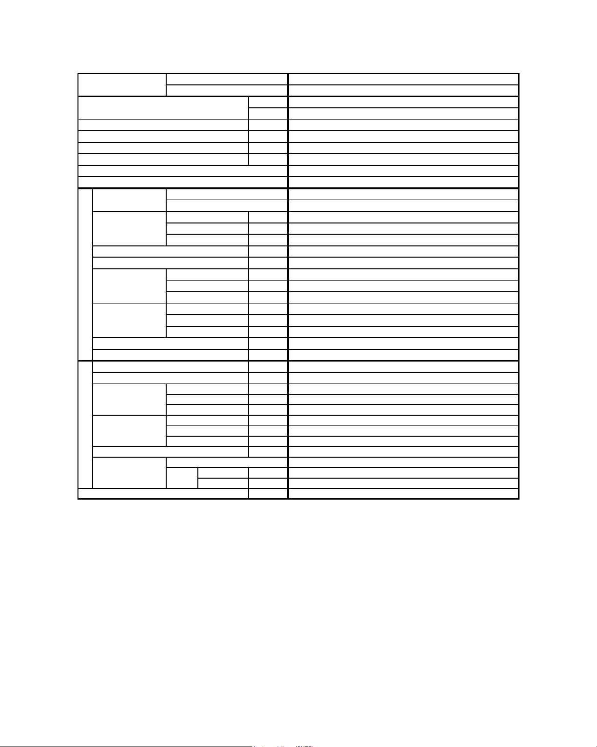
5. ENGINEERING AND PHYSICAL DATA
GENERAL DATA - COOLING ONLY (R22)
MODEL
NOMINAL CAPACITY
NOMINAL TOTAL INPUT POWER
NOMINAL RUNNING CURRENT
POWER SOURCE
EER 2.82
REFRIGERANT TYPE R22
REFRIGERANT CONTROL (EXPANSION DEVICE)
CONTROL
AIR FLO W
EXTERNAL STATIC PRESSURE (H/M/L) Pa / in.wg.
SOUND PRESSURE LEVEL (H/M/L)
UNIT DIMENSION
INDOOR UNIT
PACKING
DIMENSION
UNIT WEIGHT
CONDENSATE DRAIN SIZE
AIR FLO W
SOUND PRESSURE LEVEL
UNIT DIMENSION
PACKING
DIMENSION
OUTDOOR UNIT
UNIT WEIGHT
PIPE CONNECTION
REFRIGERANT CHARGE
1) ALL SPECIFICATIONS ARE SUBJECTED TO CHANGE BY THE MANUFACTURER WITHOUT PRIOR NOTICE.
2) ALL UNITS ARE BEING TESTED AND COMPLY TO ISO 5151.
3) NOMINAL COOLING AND HEATING CAPACITY ARE BASED ON THE CONDITIONS BELOW :
COOLING - 27°C DB / 19°C WB INDOOR AND 35°C DB / 24°C WB OUTDOOR
4) SOUND PRESSURE LEVEL ARE ACCORDING TO JIS B 8615 STANDARD. POSITION OF THE MEASUREMENT POINT IS 1m IN FRONT AND
1m BELOW THE UNIT.
AIR DISCHARGE
OPERATION
SIZE
INDOOR UNIT
OUTDOOR UNIT
HIGH
MEDIUM
LOW
HEIGHT
WIDTH
DEPTH
HEIGHT
WIDTH
DEPTH
HEIGHT
WIDTH
DEPTH
HEIGHT
WIDTH
DEPTH
TYPE
LIQUID mm/in
GAS mm/in
Btu/h
W
W
A
V/Ph/Hz
W/W
AUTOMATIC LOUVER (UP & DOWN)
WIRELESS OR WIRED MICROCOMPUTER REMOTE CONTROL
l/s / CFM
l/s / CFM
l/s / CFM
dBA
mm/in
mm/in
mm/in
mm/in
mm/in
mm/in
kg/lb
mm/in
l/s / CFM
dBA
mm/in
mm/in
mm/in
mm/in
mm/in
mm/in
kg/lb
kg/lb
ACM 15E
ALC 1 5C
12000
3520
1250
5.6
220 - 240 / 1 / 50
OUTDOOR CAP. TUBE
240 / 508
182 / 386
165 / 350
0
48 / 43 / 41
218 / 8.6
1080 / 42.5
630 / 24.8
297 / 11.7
1197 / 47.1
740 / 29.1
26
19.1 / 3/4
453 / 960
49
540 / 21.3
700 / 27.6
250 / 9.8
620 / 24.4
810 / 31.9
330 / 13.0
32 / 71
FLARE VALVE
6.4 / 1/4
12.7 / 1/2
0.60 / 1.32
31
Page 34

32
GENERAL DATA - COOLING ONLY (R22)
1) ALL SPECIFICATIONS ARE SUBJECTED TO CHANGE BY THE MANUFACTURER WITHOUT PRIOR NOTICE.
2) ALL UNITS ARE BEING TESTED AND COMPLY TO ISO 5151.
3) NOMINAL COOLING AND HEATING CAPACITY ARE BASED ON THE CONDITIONS BELOW :
COOLING - 27°C DB / 19°C WB INDOOR AND 35°C DB / 24°C WB OUTDOOR
4) SOUND PRESSURE LEVEL ARE ACCORDING TO JIS B 8615 STANDARD. POSITION OF THE MEASUREMENT POINT IS 1m IN FRONT AND
1m BELOW THE UNIT.
ALC 1 8C ALC 20C
Btu/h 18000 19000
W 5280 5570
W
1870 1861
A 8.4 8.0
V/Ph/Hz 220 - 240 / 1 / 50 220 - 240 / 1 / 50
W/W
2.82 2.99
l/s / CFM
l/s / CFM
l/s / CFM
EXTERNAL STATIC PRESSURE (H/M/L) Pa / in.wg.
dBA
mm/in
mm/in
mm/in
mm/in
mm/in
mm/in
kg/lb
mm/in
l/s / CFM
dBA
mm/in
mm/in
mm/in
mm/in
mm/in
mm/in
kg/lb
58 / 128 59 / 130
LIQUID mm/in
GAS mm/in
kg/lb 0.85 / 1.87 1.35 / 2.98
614 / 1300
51
19.1 / 3/4
740 / 29.1
297 / 11.7
1080 / 42.5
27 / 60
1197 / 47.1
630 / 24.8
648 / 25.5
15 9 / 5/8
415 / 16.3
710 / 28.0
855 / 33.7
FLARE VALVE
6.4 / 1/4
990 / 39.0
328 / 12.9
218 / 8.6
ACM 20E
R22
192 / 406
245 / 520
217 / 460
WIRELESS OR WIRED MICROCOMPUTER REMOTE CONTROL
AUTOMATIC LOUVER (UP & DOWN)
48 / 46 / 43SOUND PRESSURE LEVEL (H/M/L)
AIR FLO W
HIGH
MEDIUM
CONTROL
AIR DISCHARGE
OPERATION
0
MODEL
OUTDOOR UNIT
LOW
INDOOR UNIT
NOMINAL CAPACITY
NOMINAL TOTAL INPUT POWER
NOMINAL RUNNING CURRENT
POWER SOURCE
REFRIGERANT TYPE
INDOOR UNIT
UNIT DIMENSION
SOUND PRESSURE LEVEL
PACKING
DIMENSION
HEIGHT
WIDTH
DEPTH
UNIT WEIGHT
HEIGHT
DEPTH
DEPTH
CONDENSATE DRAIN SIZE
OUTDOOR CAP. TUBE
PACKING
DIMENSION
HEIGHT
WIDTH
DEPTH
HEIGHT
WIDTH
UNIT DIMENSION
EER
REFRIGERANT CONTROL (EXPANSION DEVICE)
REFRIGERANT CHARGE
OUTDOOR UNIT
UNIT WEIGHT
PIPE CONNECTION
TYPE
SIZE
WIDTH
AIR FLO W
Page 35
33
GENERAL DATA - COOLING ONLY (R22)
1) ALL SPECIFICATIONS ARE SUBJECTED TO CHANGE BY THE MANUFACTURER WITHOUT PRIOR NOTICE.
2) ALL UNITS ARE BEING TESTED AND COMPLY TO ISO 5151.
3) NOMINAL COOLING AND HEATING CAPACITY ARE BASED ON THE CONDITIONS BELOW :
COOLING - 27°C DB / 19°C WB INDOOR AND 35°C DB / 24°C WB OUTDOOR
4) SOUND PRESSURE LEVEL ARE ACCORDING TO JIS B 8615 STANDARD. POSITION OF THE MEASUREMENT POINT IS 1m IN FRONT AND
1m BELOW THE UNIT.
Btu/h
W
W
A
V/Ph/Hz
W/W
l/s / CFM
l/s / CFM
l/s / CFM
EXTERNAL STATIC PRESSURE (H/M/L) Pa / in.wg.
dBA
mm/in
mm/in
mm/in
mm/in
mm/in
mm/in
kg/lb
mm/in
l/s / CFM
dBA
mm/in
mm/in
mm/in
mm/in
mm/in
mm/in
kg/lb
LIQUID mm/in
GAS mm/in
kg/lb
REFRIGERANT CHARGE
OUTDOOR UNIT
CONTROL
AIR DISCHARGE
AIR FLO W
DEPTH
UNIT WEIGHT
PIPE CONNECTION
TYPE
OPERATION
WIRELESS OR WIRED MICROCOMPUTER REMOTE CONTROL
7030
REFRIGERANT TYPE
INDOOR UNIT
27 / 60
1197 / 47.1
630 / 24.8
218 / 8.6
DEPTH
UNIT WEIGHT
1.50 / 3.31
62 / 137
755 / 1600
52
750 / 29.5
15 9 / 5/8
415 / 16.3
810 / 31.9
855 / 33.7
FLARE VALVE
SIZE
HEIGHT
WIDTH
DEPTH
CONDENSATE DRAIN SIZE
UNIT DIMENSION
SOUND PRESSURE LEVEL
PACKING
DIMENSION
HEIGHT
WIDTH
PACKING
DIMENSION
HEIGHT
WIDTH
DEPTH
HEIGHT
WIDTH
UNIT DIMENSION
MODEL
OUTDOOR UNIT
LOW
INDOOR UNIT
NOMINAL CAPACITY
NOMINAL TOTAL INPUT POWER
NOMINAL RUNNING CURRENT
POWER SOURCE
2573
24000
11.5
SOUND PRESSURE LEVEL (H/M/L)
AIR FLO W
HIGH
MEDIUM
0
50 / 47 / 46
AUTOMATIC LOUVER (UP & DOWN)
740 / 29.1
297 / 11.7
1080 / 42.5
ACM 25E
220 - 240 / 1 / 50
R22
231 / 490
274 / 580
250 / 530
ALC 2 5C
9.5 / 3/8
990 / 39.0
328 / 12.9
19.1 / 3/4
OUTDOOR CAP. TUBE
2.73
EER
REFRIGERANT CONTROL (EXPANSION DEVICE)
Page 36

34
GENERAL DATA - COOLING ONLY (R22)
1) ALL SPECIFICATIONS ARE SUBJECTED TO CHANGE BY THE MANUFACTURER WITHOUT PRIOR NOTICE.
2) ALL UNITS ARE BEING TESTED AND COMPLY TO ISO 5151.
3) NOMINAL COOLING AND HEATING CAPACITY ARE BASED ON THE CONDITIONS BELOW :
COOLING - 27°C DB / 19°C WB INDOOR AND 35°C DB / 24°C WB OUTDOOR
4) SOUND PRESSURE LEVEL ARE ACCORDING TO JIS B 8615 STANDARD. POSITION OF THE MEASUREMENT POINT IS 1m IN FRONT AND
1m BELOW THE UNIT.
ALC 2 8C ALC 30C
Btu/h 28000 28000
W 8210 8210
W
2811 2747
A 13.6 13.3
V/Ph/Hz 220 - 240 / 1 / 50 220 - 240 / 1 / 50
W/W 2.92 2.99
l/s / CFM
l/s / CFM
l/s / CFM
EXTERNAL STATIC PRESSURE (H/M/L) Pa / in.wg.
dBA
mm/in
mm/in
mm/in
mm/in
mm/in
mm/in
kg/lb
mm/in
l/s / CFM 741 / 1570 1605 / 3400
dBA 54 58
mm/in
750 / 29.5 850 / 33.46
mm/in 855 / 33.7 1030 / 40.55
mm/in 328 / 12.9 400 / 15.75
mm/in
810 / 31.9 1000 / 39.37
mm/in
990 / 39.0 1200 / 47.24
mm/in 415 / 16.3 560 / 22.05
kg/lb 68 / 150 95 / 209
LIQUID mm/in 9.5 / 3/8 9.5 / 3/8
GAS mm/in 15.9 / 5/8 15.9 / 5/8
kg/lb 2.40 / 5.3 1.40 / 3.09
OUTDOOR UNIT
REFRIGERANT CHARGE
CONTROL
AIR DISCHARGE
SOUND PRESSURE LEVEL (H/M/L)
AIR FLO W
HIGH
MEDIUM
CONDENSATE DRAIN SIZE
PIPE CONNECTION
FLARE VALVE
218 / 8.6
19.1 / 3/4
740 / 29.1
297 / 11.7
1080 / 42.5
630 / 24.8
217 / 460
302 / 640
264 / 560
INDOOR CAP. TUBE
AUTOMATIC LOUVER (UP & DOWN)
WIRELESS OR WIRED MICROCOMPUTER REMOTE CONTROL
ACM 28E
R22 REFRIGERANT TYPE
OPERATION
0
INDOOR UNIT
UNIT WEIGHT
HEIGHT
WIDTH
28 / 62
1197 / 47.1
56 / 51 / 44
MODEL
OUTDOOR UNIT
LOW
INDOOR UNIT
NOMINAL CAPACITY
NOMINAL TOTAL INPUT POWER
NOMINAL RUNNING CURRENT
REFRIGERANT CONTROL (EXPANSION DEVICE)
EER
POWER SOURCE
TYPE
SIZE
DEPTH
PACKING
DIMENSION
HEIGHT
WIDTH
DEPTH
HEIGHT
WIDTH
UNIT WEIGHT
AIR FLO W
DEPTH
UNIT DIMENSION
SOUND PRESSURE LEVEL
UNIT DIMENSION
PACKING
DIMENSION
HEIGHT
WIDTH
DEPTH
Page 37

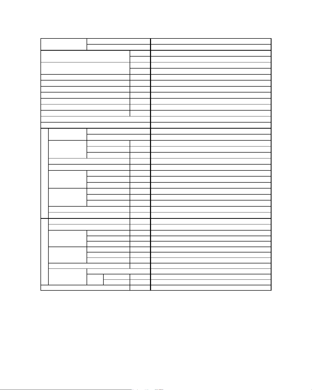
GENERAL DATA - HEATPUMP (R22)
35
1) ALL SPECIFICATIONS ARE SUBJECTED TO CHANGE BY THE MANUFACTURER WITHOUT PRIOR NOTICE.
2) ALL UNITS ARE BEING TESTED AND COMPLY TO ISO 5151.
3) NOMINAL COOLING AND HEATING CAPACITY ARE BASED ON THE CONDITIONS BELOW :
a) COOLING - 27°C DB / 19°C WB INDOOR AND 35°C DB / 24°C WB OUTDOOR
b) HEATING - 20°C DB INDOOR AND 7°C DB / 6°C WB OUTDOOR
4) SOUND PRESSURE LEVEL ARE ACCORDING TO JIS B 8615 STANDARD. POSITION OF THE MEASUREMENT POINT IS 1m IN FRONT AND 1m
BELOW THE UNIT.
Btu/h
W
Btu/h
W
W
W
A
A
V/Ph/Hz
W/W
W/W
l/s / CFM
l/s / CFM
l/s / CFM
EXTERNAL STATIC PRESSURE (H/M/L) Pa / in.wg.
dBA
mm/in
mm/in
mm/in
mm/in
mm/in
mm/in
kg/lb
mm/in
l/s / CFM
dBA
mm/in
mm/in
mm/in
mm/in
mm/in
mm/in
kg/lb
LIQUID mm/in
GAS mm/in
kg/lb
AIR FLO W
NOMINAL RUNNING CURRENT (COOLING)
NOMINAL RUNNING CURRENT (HEATING)
POWER SOURCE
REFRIGERANT TYPE
EER
COP
REFRIGERANT CONTROL (EXPANSION DEVICE)
NOMINAL COOLING CAPACITY
NOMINAL HEATING CAPACITY
NOMINAL TOTAL INPUT POW ER (COOLING)
NOMINAL TOTAL INPUT POWER (HEATING)
WIDTH
LOW
INDOOR UNIT
CONTROL
AIR DISCHARGE
HIGH
MEDIUM
MODEL
OUTDOOR UNIT
SOUND PRESSURE LEVEL (H/M/L)
UNIT DIMENSION
SOUND PRESSURE LEVEL
PACKING
DIMENSION
HEIGHT
WIDTH
DEPTH
DEPTH
HEIGHT
WIDTH
220 - 240 / 1 / 50
R22
HEIGHT
WIDTH
UNIT WEIGHT
CONDENSATE DRAIN SIZE
UNIT DIMENSION
DEPTH
UNIT WEIGHT
PIPE CONNECTION
TYPE
SIZE
OUTDOOR UNIT
REFRIGERANT CHARGE
AUTOMATIC LOUVER (UP & DOWN)
OPERATION WIRELESS OR WIRED MICROCOMPUTER REMOTE CONTROL
INDOOR UNIT
AIR FLO W
DEPTH
PACKING
DIMENSION
HEIGHT
1.20 / 2.65
6.4 / 1/4
32 / 71
810 / 31.9
FLARE VALVE
250 / 9.8
540 / 21.3
453 / 960
12.7 / 1/2
330 / 13.0
620 / 24.4
700 / 27.6
49
19.1 / 3/4
740 / 29.1
297 / 11.7
1080 / 42.5
26
1197 / 47.1
630 / 24.8
218 / 8.6
1250
12000
12000
48 / 43 / 41
165 / 350
240 / 508
0
182 / 386
OUTDOOR CAP. TUBE
2.82
3.53
ACM 15E R
4.5
998
3520
3520
ALC 1 5CR
5.6
Page 38

GENERAL DATA - HEATPUMP (R22)
36
1) ALL SPECIFICATIONS ARE SUBJECTED TO CHANGE BY THE MANUFACTURER WITHOUT PRIOR NOTICE.
2) ALL UNITS ARE BEING TESTED AND COMPLY TO ISO 5151.
3) NOMINAL COOLING AND HEATING CAPACITY ARE BASED ON THE CONDITIONS BELOW :
a) COOLING - 27°C DB / 19°C WB INDOOR AND 35°C DB / 24°C WB OUTDOOR
b) HEATING - 20°C DB INDOOR AND 7°C DB / 6°C WB OUTDOOR
4) SOUND PRESSURE LEVEL ARE ACCORDING TO JIS B 8615 STANDARD. POSITION OF THE MEASUREMENT POINT IS 1m IN FRONT AND 1m
BELOW THE UNIT.
ALC 18CR ALC 20CR
Btu/h 18000 19000
W 5280 5570
Btu/h
18500 19500
W 5420 5720
W 1870 1861
W
1710 1811
A
8.4 8.2
A 7.7 8.0
V/Ph/Hz 220 - 240 / 1 / 50 220 - 240 / 1 / 50
W/W
2.82 2.99
W/W 3.17 3.16
l/s / CFM
l/s / CFM
l/s / CFM
EXTERNAL STATIC PRESSURE (H/M/L) Pa / in.wg.
dBA
mm/in
mm/in
mm/in
mm/in
mm/in
mm/in
kg/lb
mm/in
l/s / CFM
dBA
mm/in
mm/in
mm/in
mm/in
mm/in
mm/in
kg/lb 58 / 128 59 / 130
LIQUID mm/in
GAS mm/in
kg/lb 0.85 / 1.87 1.35 / 2.98
15 9 / 5/8
1080 / 42.5
19.1 / 3/4
614 / 1300
AUTOMATIC LOUVER (UP & DOWN)
51
6.4 / 1/4
SIZE
HEIGHT
ACM 20E R
FLARE VALVE
990 / 39.0
328 / 12.9
648 / 25.5
415 / 16.3
710 / 28.0
855 / 33.7
192 / 406
0
REFRIGERANT CHARGE
AIR FLO W
PACKING
DIMENSION
HEIGHT
DEPTH
UNIT WEIGHT
PIPE CONNECTION
TYPE
UNIT DIMENSION WIDTH
WIRELESS OR WIRED MICROCOMPUTER REMOTE CONTROL
INDOOR UNIT
DEPTH
27 / 60
UNIT WEIGHT
1197 / 47.1
630 / 24.8
218 / 8.6
AIR FLO W
CONDENSATE DRAIN SIZE
HEIGHT
WIDTH
LOW
MEDIUM
OPERATION
OUTDOOR UNIT
COP
245 / 520
740 / 29.1
217 / 460
297 / 11.7
48 / 46 / 43
WIDTH
SOUND PRESSURE LEVEL (H/M/L)
SOUND PRESSURE LEVEL
PACKING
DIMENSION
HEIGHT
WIDTH
DEPTH
DEPTH
INDOOR UNIT
CONTROL
AIR DISCHARGE
HIGH
MODEL
OUTDOOR UNIT
NOMINAL COOLING CAPACITY
NOMINAL HEATING CAPACITY
UNIT DIMENSION
R22
NOMINAL TOTAL INPUT POW ER (COOLING)
NOMINAL TOTAL INPUT POWER (HEATING)
OUTDOOR CAP. TUBEREFRIGERANT CONTROL (EXPANSION DEVICE)
NOMINAL RUNNING CURRENT (COOLING)
NOMINAL RUNNING CURRENT (HEATING)
POWER SOURCE
REFRIGERANT TYPE
EER
Page 39

GENERAL DATA - HEATPUMP (R22)
37
1) ALL SPECIFICATIONS ARE SUBJECTED TO CHANGE BY THE MANUFACTURER WITHOUT PRIOR NOTICE.
2) ALL UNITS ARE BEING TESTED AND COMPLY TO ISO 5151.
3) NOMINAL COOLING AND HEATING CAPACITY ARE BASED ON THE CONDITIONS BELOW :
a) COOLING - 27°C DB / 19°C WB INDOOR AND 35°C DB / 24°C WB OUTDOOR
b) HEATING - 20°C DB INDOOR AND 7°C DB / 6°C WB OUTDOOR
4) SOUND PRESSURE LEVEL ARE ACCORDING TO JIS B 8615 STANDARD. POSITION OF THE MEASUREMENT POINT IS 1m IN FRONT AND 1m
BELOW THE UNIT.
Btu/h
W
Btu/h
W
W
W
A
A
V/Ph/Hz
W/W
W/W
l/s / CFM
l/s / CFM
l/s / CFM
EXTERNAL STATIC PRESSURE (H/M/L) Pa / in.wg.
dBA
mm/in
mm/in
mm/in
mm/in
mm/in
mm/in
kg/lb
mm/in
l/s / CFM
dBA
mm/in
mm/in
mm/in
mm/in
mm/in
mm/in
kg/lb
LIQUID mm/in
GAS mm/in
kg/lb
OUTDOOR UNIT
REFRIGERANT CHARGE
AUTOMATIC LOUVER (UP & DOWN)
OPERATION WIRELESS OR WIRED MICROCOMPUTER REMOTE CONTROL
INDOOR UNIT
AIR FLO W
DEPTH
PACKING
DIMENSION
HEIGHT
DEPTH
UNIT WEIGHT
PIPE CONNECTION
TYPE
SIZE
DEPTH
HEIGHT
WIDTH
220 - 240 / 1 / 50
R22
HEIGHT
WIDTH
UNIT WEIGHT
CONDENSATE DRAIN SIZE
UNIT DIMENSION
UNIT DIMENSION
SOUND PRESSURE LEVEL
PACKING
DIMENSION
HEIGHT
WIDTH
DEPTH
WIDTH
LOW
INDOOR UNIT
CONTROL
AIR DISCHARGE
HIGH
MEDIUM
MODEL
OUTDOOR UNIT
SOUND PRESSURE LEVEL (H/M/L)
NOMINAL COOLING CAPACITY
NOMINAL HEATING CAPACITY
NOMINAL TOTAL INPUT POW ER (COOLING)
NOMINAL TOTAL INPUT POWER (HEATING)
AIR FLO W
NOMINAL RUNNING CURRENT (COOLING)
NOMINAL RUNNING CURRENT (HEATING)
POWER SOURCE
REFRIGERANT TYPE
EER
COP
REFRIGERANT CONTROL (EXPANSION DEVICE)
ACM 25E R
50 / 47 / 46
231 / 490
274 / 580
11.5
11.2
2493
7330
7030
ALC 2 5CR
2573
25000
24000
0
250 / 530
2.73
2.94
OUTDOOR CAP. TUBE
1.50 / 3.31
9.5 / 3/8
62 / 137
990 / 39.0
FLARE VALVE
15 9 / 5/8
415 / 16.3
328 / 12.9
750 / 29.5
755 / 1600
19.1 / 3/4
810 / 31.9
855 / 33.7
52
218 / 8.6
740 / 29.1
297 / 11.7
1080 / 42.5
27 / 60
1197 / 47.1
630 / 24.8
Page 40

GENERAL DATA - HEATPUMP (R22)
38
1) ALL SPECIFICATIONS ARE SUBJECTED TO CHANGE BY THE MANUFACTURER WITHOUT PRIOR NOTICE.
2) ALL UNITS ARE BEING TESTED AND COMPLY TO ISO 5151.
3) NOMINAL COOLING AND HEATING CAPACITY ARE BASED ON THE CONDITIONS BELOW :
a) COOLING - 27°C DB / 19°C WB INDOOR AND 35°C DB / 24°C WB OUTDOOR
b) HEATING - 20°C DB INDOOR AND 7°C DB / 6°C WB OUTDOOR
4) SOUND PRESSURE LEVEL ARE ACCORDING TO JIS B 8615 STANDARD. POSITION OF THE MEASUREMENT POINT IS 1m IN FRONT AND 1m
BELOW THE UNIT.
ALC 28CR ALC 30CR
Btu/h 28000 28000
W 8210 8210
Btu/h
28500 28500
W 8350 8350
W 2862 2747
W
2902 2954
A
13.7 13.3
A 13.8 14.1
V/Ph/Hz 220 - 240 / 1 / 50 220 - 240 / 1 / 50
W/W
2.87 2.99
W/W 2.88 2.83
R22 R22
OUTDOOR CAP. TUBE OUTDOOR CAP TUBE + TXV
l/s / CFM
l/s / CFM
l/s / CFM
EXTERNAL STATIC PRESSURE (H/M/L) Pa / in.wg.
dBA
mm/in
mm/in
mm/in
mm/in
mm/in
mm/in
kg/lb
mm/in
l/s / CFM
741 / 1570 1605 / 3400
dBA 54 58
mm/in 750 / 29.5 850 / 33.5
mm/in 855 / 33.7 1030 / 40.6
mm/in 328 / 12.9 400 / 15.8
mm/in
810 / 31.9 1000 / 39.4
mm/in 990 / 39.0 1200 / 47.2
mm/in 415 / 16.3 560 / 22.1
kg/lb 68 / 150 95 / 209
LIQUID mm/in 9.5 / 3/8 9.5 / 3/8
GAS mm/in 15.9 / 5/8 15.9 / 5/8
kg/lb 2.40 / 5.30 2.15 / 4.12
REFRIGERANT CHARGE
AUTOMATIC LOUVER (UP & DOWN)
OPERATION WIRELESS OR WIRED MICROCOMPUTER REMOTE CONTROL
INDOOR UNIT
0
28 / 62
1197 / 47.1
630 / 24.8
FLARE VALVE
OUTDOOR UNIT
ACM 28E R
19.1 / 3/4
740 / 29.1
297 / 11.7
1080 / 42.5
56 / 51 / 44
217 / 460
302 / 640
264 / 560
218 / 8.6
SOUND PRESSURE LEVEL (H/M/L)
NOMINAL COOLING CAPACITY
NOMINAL HEATING CAPACITY
NOMINAL TOTAL INPUT POW ER (COOLING)
NOMINAL TOTAL INPUT POWER (HEATING)
NOMINAL RUNNING CURRENT (COOLING)
NOMINAL RUNNING CURRENT (HEATING)
POWER SOURCE
REFRIGERANT TYPE
INDOOR UNIT
CONTROL
AIR DISCHARGE
HIGH
MODEL
OUTDOOR UNIT
EER
REFRIGERANT CONTROL (EXPANSION DEVICE)
WIDTH
AIR FLO W
LOW
MEDIUM
WIDTH
AIR FLO W
COP
UNIT DIMENSION
SOUND PRESSURE LEVEL
PACKING
DIMENSION
HEIGHT
WIDTH
DEPTH
HEIGHT
UNIT WEIGHT
PIPE CONNECTION
TYPE
SIZE
DEPTH
PACKING
DIMENSION
HEIGHT
WIDTH
DEPTH
UNIT WEIGHT
CONDENSATE DRAIN SIZE
UNIT DIMENSION
DEPTH
HEIGHT
Page 41

39
GENERAL DATA - COOLING ONLY (R410A)
1) ALL SPECIFICATIONS ARE SUBJECTED TO CHANGE BY THE MANUFACTURER WITHOUT PRIOR NOTICE.
2) ALL UNITS ARE BEING TESTED AND COMPLY TO ISO 5151.
3) NOMINAL COOLING AND HEATING CAPACITY ARE BASED ON THE CONDITIONS BELOW :
COOLING - 27°C DB / 19°C WB INDOOR AND 35°C DB / 24°C WB OUTDOOR
4) SOUND PRESSURE LEVEL ARE ACCORDING TO JIS B 8615 STANDARD. POSITION OF THE MEASUREMENT POINT IS 1m IN FRONT AND
1m BELOW THE UNIT.
Btu/h
W
W
A
V/Ph/Hz
W/W
l/s / CFM
l/s / CFM
l/s / CFM
EXTERNAL STATIC PRESSURE (H/M/L) Pa / in.wg.
dBA
mm/in
mm/in
mm/in
mm/in
mm/in
mm/in
kg/lb
mm/in
l/s / CFM
dBA
mm/in
mm/in
mm/in
mm/in
mm/in
mm/in
kg/lb
LIQUID mm/in
GAS mm/in
kg/lb
0.83 / 1.83
32 / 71
453 / 960
49
540 / 21.3
12.7 / 1/2
330 / 13.0
620 / 24.4
700 / 27.6
FLARE VALVE
5.8
3780
A5LC 15C
1280
12900
297 / 11.7
1080 / 42.5
26
630 / 24.8
6.4 / 1/4
810 / 31.9
250 / 9.8
1197 / 47.1
19.1 / 3/4
740 / 29.1
218 / 8.6
A5CM 15E
220 - 240 / 1 / 50
R410A
165 / 350
240 / 508
182 / 386
WIRELESS OR WIRED MICROCOMPUTER REMOTE CONTROL
AUTOMATIC LOUVER (UP & DOWN)
48 / 43 / 41SOUND PRESSURE LEVEL (H/M/L)
AIR FLO W
HIGH
MEDIUM
CONTROL
AIR DISCHARGE
OPERATION
0
MODEL
OUTDOOR UNIT
LOW
INDOOR UNIT
NOMINAL CAPACITY
NOMINAL TOTAL INPUT POWER
NOMINAL RUNNING CURRENT
POWER SOURCE
REFRIGERANT TYPE
INDOOR UNIT
CONDENSATE DRAIN SIZE
UNIT DIMENSION
UNIT DIMENSION
SOUND PRESSURE LEVEL
PACKING
DIMENSION
HEIGHT
WIDTH
DEPTH
UNIT WEIGHT
HEIGHT
WIDTH
DEPTH
PACKING
DIMENSION
HEIGHT
WIDTH
DEPTH
HEIGHT
WIDTH
AIR FLO W
DEPTH
REFRIGERANT CHARGE
OUTDOOR UNIT
UNIT WEIGHT
PIPE CONNECTION
TYPE
SIZE
EER
REFRIGERANT CONTROL (EXPANSION DEVICE)
2.95
OUTDOOR CAP. TUBE
Page 42

40
GENERAL DATA - COOLING ONLY (R410A)
1) ALL SPECIFICATIONS ARE SUBJECTED TO CHANGE BY THE MANUFACTURER WITHOUT PRIOR NOTICE.
2) ALL UNITS ARE BEING TESTED AND COMPLY TO ISO 5151.
3) NOMINAL COOLING AND HEATING CAPACITY ARE BASED ON THE CONDITIONS BELOW :
COOLING - 27°C DB / 19°C WB INDOOR AND 35°C DB / 24°C WB OUTDOOR
4) SOUND PRESSURE LEVEL ARE ACCORDING TO JIS B 8615 STANDARD. POSITION OF THE MEASUREMENT POINT IS 1m IN FRONT AND
1m BELOW THE UNIT.
A5CM 20E A5CM 25E
A5LC 20C A5LC 25C
Btu/h 17500 / <18100> 20000 / <22860>
W 5130 / <5300> 5860 / <6700>
W
1723 / <1757> 1973 / <2231>
A 7.6 / <3.3> 8.8 / <4.2>
V/Ph/Hz
W/W 2.98 / <3.02> 2.97 / <3.00>
l/s / CFM
245 / 520 274 / 580
l/s / CFM 217 / 460 250 / 530
l/s / CFM 192 / 406 231 / 490
EXTERNAL STATIC PRESSURE (H/M/L) Pa / in.wg. 00
dBA
48 / 46 / 43 50 / 47 / 46
mm/in
mm/in
mm/in
mm/in
mm/in
mm/in
kg/lb
mm/in
l/s / CFM 614 / 1300 689 / 1460
dBA 52 52
mm/in
648 / 25.5 750 / 29.5
mm/in 855 / 33.7 855 / 33.7
mm/in 328 / 12.9 328 / 12.9
mm/in 710 / 28.0 810 / 31.9
mm/in
990 / 39.0 990 / 39.0
mm/in 415 / 16.3 415 / 16.3
kg/lb 59 / 130 62 / 137
LIQUID mm/in 6.4 / 1/4 6.4 / 1/4
GAS mm/in 12.7 / 1/2 15.9 / 5/8
kg/lb 1.40 / 3.09 1.65 / 3.64
REFRIGERANT CHARGE
WIRELESS OR WIRED MICROCOMPUTER REMOTE CONTROL
INDOOR UNIT
AIR FLO W
DEPTH
UNIT WEIGHT
PIPE CONNECTION
TYPE
SIZE
OUTDOOR UNIT
PACKING
DIMENSION
HEIGHT
WIDTH
DEPTH
HEIGHT
WIDTH
UNIT DIMENSION
SOUND PRESSURE LEVEL
PACKING
DIMENSION
HEIGHT
WIDTH
DEPTH
UNIT WEIGHT
CONDENSATE DRAIN SIZE
NOMINAL TOTAL INPUT POW ER - 1Ø / <3Ø>
NOMINAL RUNNING CURRENT - 1Ø / <3Ø>
POWER SOURCE
REFRIGERANT TYPE
EER - 1Ø / <3Ø>
MODEL
OUTDOOR UNIT
INDOOR UNIT
NOMINAL CAPACITY - 1Ø / <3Ø>
220 - 240 / 1 / 50 / <380 - 415 / 3 / 50>
R410A
SOUND PRESSURE LEVEL (H/M/L)
AIR FLO W
HIGH
MEDIUM
LOW
CONTROL
AIR DISCHARGE
AUTOMATIC LOUVER (UP & DOWN)
FLARE VALVE
19.1 / 3/4
740 / 29.1
297 / 11.7
27 / 60
1197 / 47.1
REFRIGERANT CONTROL (EXPANSION DEVICE)
OUTDOOR CAP. TUBE
HEIGHT 218 / 8.6
OPERATION
UNIT DIMENSION WIDTH
DEPTH
1080 / 42.5
630 / 24.8
Page 43

41
GENERAL DATA - COOLING ONLY (R410A)
1) ALL SPECIFICATIONS ARE SUBJECTED TO CHANGE BY THE MANUFACTURER WITHOUT PRIOR NOTICE.
2) ALL UNITS ARE BEING TESTED AND COMPLY TO ISO 5151.
3) NOMINAL COOLING AND HEATING CAPACITY ARE BASED ON THE CONDITIONS BELOW :
COOLING - 27°C DB / 19°C WB INDOOR AND 35°C DB / 24°C WB OUTDOOR
4) SOUND PRESSURE LEVEL ARE ACCORDING TO JIS B 8615 STANDARD. POSITION OF THE MEASUREMENT POINT IS 1m IN FRONT AND
1m BELOW THE UNIT.
A5LC 28C A5LC 35C
Btu/h 26000 / <26000> 30000 / <30000>
W 7620/ <7620> 8790 / <8790>
W
2670 / <2715> 2917 / <2817>
A 12.6 / <4.7> 14.5 / <3.6>
V/Ph/Hz
W/W 2.85 / <2.81> 3.01 / <3.12>
R410A R410A
OUTDOOR CAP. TUBE OUTDOOR CAP. TUBE & TXV
l/s / CFM
l/s / CFM
l/s / CFM
EXTERNAL STATIC PRESSURE (H/M/L) Pa / in.wg.
dBA
mm/in
mm/in
mm/in
mm/in
mm/in
mm/in
kg/lb
mm/in
l/s / CFM 684 / 1450 1605 / 3400
dBA 54 58
mm/in
750 / 29.5 850 / 33.5
mm/in 855 / 33.7 1030 / 40.6
mm/in 328 / 12.9 400 / 15.8
mm/in 810 / 31.9 1000 / 39.4
mm/in
990 / 39.0 1200 / 47.2
mm/in 415 / 16.3 560 / 22.1
kg/lb 68 / 150 95 / 209
LIQUID mm/in 9.5 / 3/8 9.5 / 3/8
GAS mm/in 15.9 / 5/8 15.9 / 5/8
kg/lb 1.70 / 3.75 1.90 / 4.19
REFRIGERANT CHARGE
0
56 / 51 / 44
28 / 62
1197 / 47.1
AIR FLO W
DEPTH
UNIT WEIGHT
PIPE CONNECTION
TYPE
HEIGHT
WIDTH
DEPTH
PACKING
DIMENSION
HEIGHT
WIDTH
DEPTH
WIDTH
UNIT WEIGHT
CONDENSATE DRAIN SIZE
SIZE
UNIT DIMENSION
PACKING
DIMENSION
HEIGHT
WIDTH
DEPTH
POWER SOURCE
REFRIGERANT TYPE
INDOOR UNIT
HEIGHT
CONTROL
AIR DISCHARGE
OPERATION
OUTDOOR UNIT
AIR FLO W
HIGH
MEDIUM
MODEL
OUTDOOR UNIT
LOW
INDOOR UNIT
NOMINAL CAPACITY - 1Ø / <3Ø>
NOMINAL TOTAL INPUT POW ER - 1Ø / <3Ø>
NOMINAL RUNNING CURRENT - 1Ø / <3Ø>
EER - 1Ø / <3Ø>
REFRIGERANT CONTROL (EXPANSION DEVICE)
A5CM 28E
217 / 460
302 / 640
264 / 560
220 - 240 / 1 / 50 / <380 - 415 / 3 / 50>
AUTOMATIC LOUVER (UP & DOWN)
WIRELESS OR WIRED MICROCOMPUTER REMOTE CONTROL
SOUND PRESSURE LEVEL (H/M/L)
FLARE VALVE
218 / 8.6
19.1 / 3/4
740 / 29.1
297 / 11.7
1080 / 42.5
630 / 24.8
UNIT DIMENSION
SOUND PRESSURE LEVEL
Page 44
GENERAL DATA - HEATPUMP (R410A)
42
1) ALL SPECIFICATIONS ARE SUBJECTED TO CHANGE BY THE MANUFACTURER WITHOUT PRIOR NOTICE.
2) ALL UNITS ARE BEING TESTED AND COMPLY TO ISO 5151.
3) NOMINAL COOLING AND HEATING CAPACITY ARE BASED ON THE CONDITIONS BELOW :
a) COOLING - 27°C DB / 19°C WB INDOOR AND 35°C DB / 24°C WB OUTDOOR
b) HEATING - 20°C DB INDOOR AND 7°C DB / 6°C WB OUTDOOR
4) SOUND PRESSURE LEVEL ARE ACCORDING TO JIS B 8615 STANDARD. POSITION OF THE MEASUREMENT POINT IS 1m IN FRONT AND 1m
BELOW THE UNIT.
Btu/h
W
Btu/h
W
W
W
A
A
V/Ph/Hz
W/W
W/W
l/s / CFM
l/s / CFM
l/s / CFM
EXTERNAL STATIC PRESSURE (H/M/L) Pa / in.wg.
dBA
mm/in
mm/in
mm/in
mm/in
mm/in
mm/in
kg/lb
mm/in
l/s / CFM
dBA
mm/in
mm/in
mm/in
mm/in
mm/in
mm/in
kg/lb
LIQUID mm/in
GAS mm/in
kg/lb
A5CM 15ER
5.1
1138
3460
3780
A5LC 15CR
6.0
1268
11800
12900
48 / 43 / 41
165 / 350
240 / 508
26
1197 / 47.1
630 / 24.8
218 / 8.6
0
182 / 386
19.1 / 3/4
740 / 29.1
297 / 11.7
1080 / 42.5
250 / 9.8
540 / 21.3
453 / 960
12.7 / 1/2
330 / 13.0
620 / 24.4
700 / 27.6
49
0.83 / 1.83
6.4 / 1/4
32 / 71
810 / 31.9
FLARE VALVE
OUTDOOR UNIT
REFRIGERANT CHARGE
AUTOMATIC LOUVER (UP & DOWN)
OPERATION WIRELESS OR WIRED MICROCOMPUTER REMOTE CONTROL
INDOOR UNIT
AIR FLO W
DEPTH
PACKING
DIMENSION
HEIGHT
DEPTH
UNIT WEIGHT
PIPE CONNECTION
TYPE
SIZE
DEPTH
HEIGHT
WIDTH
220 - 240 / 1 / 50
R410A
HEIGHT
WIDTH
UNIT WEIGHT
CONDENSATE DRAIN SIZE
UNIT DIMENSION
UNIT DIMENSION
SOUND PRESSURE LEVEL
PACKING
DIMENSION
HEIGHT
WIDTH
DEPTH
WIDTH
LOW
INDOOR UNIT
CONTROL
AIR DISCHARGE
HIGH
MEDIUM
MODEL
OUTDOOR UNIT
SOUND PRESSURE LEVEL (H/M/L)
NOMINAL COOLING CAPACITY
NOMINAL HEATING CAPACITY
NOMINAL TOTAL INPUT POW ER (COOLING)
NOMINAL TOTAL INPUT POWER (HEATING)
AIR FLO W
NOMINAL RUNNING CURRENT (COOLING)
NOMINAL RUNNING CURRENT (HEATING)
POWER SOURCE
REFRIGERANT TYPE
2.98
3.04
OUTDOOR CAP. TUBE
EER
COP
REFRIGERANT CONTROL (EXPANSION DEVICE)
Page 45

GENERAL DATA - HEATPUMP (R410A)
43
1) ALL SPECIFICATIONS ARE SUBJECTED TO CHANGE BY THE MANUFACTURER WITHOUT PRIOR NOTICE.
2) ALL UNITS ARE BEING TESTED AND COMPLY TO ISO 5151.
3) NOMINAL COOLING AND HEATING CAPACITY ARE BASED ON THE CONDITIONS BELOW :
a) COOLING - 27°C DB / 19°C WB INDOOR AND 35°C DB / 24°C WB OUTDOOR
b) HEATING - 20°C DB INDOOR AND 7°C DB / 6°C WB OUTDOOR
4) SOUND PRESSURE LEVEL ARE ACCORDING TO JIS B 8615 STANDARD. POSITION OF THE MEASUREMENT POINT IS 1m IN FRONT AND 1m
BELOW THE UNIT.
A5CM 20 ER A5CM 25 ER
A5LC 20CR A5LC 25CR
Btu/h 17500 / <18100> 20000 / <26000>
W 5130 / <5300> 5860 / <6700>
Btu/h
18500 / <18770> 22000 / <23200>
W 5420 / <5500> 6450 / <6800>
W 1723 / <1757> 1973 / <2231>
W
1493 / <1527> 2003 / <2124>
A
7.6 / <3.3> 8.9 / <4.2>
A 6.6 / <2.8> 9.1 / <4.0>
V/Ph/Hz
W/W
2.98 / <3.02> 2.97 / <3.00>
W/W 3.63 / <3.60> 3.22 / <3.20>
l/s / CFM 245 / 520 274 / 580
l/s / CFM
217 / 460 250 / 530
l/s / CFM
192 / 406 231 / 490
EXTERNAL STATIC PRESSURE (H/M/L) Pa / in.wg. 00
dBA 48 / 46 / 43 50 / 47 / 46
mm/in
mm/in
mm/in
mm/in
mm/in
mm/in
kg/lb
mm/in
l/s / CFM
614 / 1300 689 / 1460
dBA 52 52
mm/in
648 / 25.5 750 / 29.5
mm/in 855 / 33.7 855 / 33.7
mm/in 328 / 12.9 328 / 12.9
mm/in
810 / 31.9 810 / 31.9
mm/in
990 / 39.0 990 / 39.0
mm/in 415 / 16.3 415 / 16.3
kg/lb 59 / 130 62 / 137
LIQUID mm/in 6.4 / 1/4 6.4 / 1/4
GAS mm/in 12.7 / 1/2 15.9 / 5/8
kg/lb
1.40 / 3.09 1.65 / 3.64
OUTDOOR UNIT
REFRIGERANT CHARGE
CONTROL
AIR DISCHARGE
OPERATION
SOUND PRESSURE LEVEL (H/M/L)
AIR FLO W
HIGH
UNIT DIMENSION
SOUND PRESSURE LEVEL
NOMINAL HEATING CAPACITY - 1Ø / <3Ø>
NOMINAL TOTAL INPUT POWER (COOLING) - 1Ø / <3Ø>
NOMINAL TOTAL INPUT POWER (HEATING) - 1Ø / <3Ø>
WIRELESS OR WIRED MICROCOMPUTER REMOTE CONTROL
INDOOR UNIT
MEDIUM
UNIT DIMENSION
PACKING
DIMENSION
HEIGHT
WIDTH
AIR FLO W
MODEL
OUTDOOR UNIT
LOW
INDOOR UNIT
NOMINAL RUNNING CURRENT (COOLING) - 1Ø / <3Ø>
NOMINAL RUNNING CURRENT (HEATING) - 1Ø / <3Ø>
POWER SOURCE
REFRIGERANT TYPE
NOMINAL COOLING CAPACITY - 1Ø / <3Ø>
HEIGHT
WIDTH
DEPTH
HEIGHT
UNIT WEIGHT
CONDENSATE DRAIN SIZE
220 - 240 / 1 / 50 / <380 - 415 / 3 / 50>
R410A
AUTOMATIC LOUVER (UP & DOWN)
WIDTH
DEPTH
HEIGHT
DEPTH
27 / 60
FLARE VALVE
DEPTH
UNIT WEIGHT
PIPE CONNECTION
TYPE
SIZE
PACKING
DIMENSION
WIDTH
1197 / 47.1
630 / 24.8
218 / 8.6
19.1 / 3/4
740 / 29.1
297 / 11.7
1080 / 42.5
OUTDOOR CAP. TUBE
EER - 1Ø / <3Ø>
COP - 1Ø / <3Ø>
REFRIGERANT CONTROL (EXPANSION DEVICE)
Page 46

GENERAL DATA - HEATPUMP (R410A)
44
1) ALL SPECIFICATIONS ARE SUBJECTED TO CHANGE BY THE MANUFACTURER WITHOUT PRIOR NOTICE.
2) ALL UNITS ARE BEING TESTED AND COMPLY TO ISO 5151.
3) NOMINAL COOLING AND HEATING CAPACITY ARE BASED ON THE CONDITIONS BELOW :
a) COOLING - 27°C DB / 19°C WB INDOOR AND 35°C DB / 24°C WB OUTDOOR
b) HEATING - 20°C DB INDOOR AND 7°C DB / 6°C WB OUTDOOR
4) SOUND PRESSURE LEVEL ARE ACCORDING TO JIS B 8615 STANDARD. POSITION OF THE MEASUREMENT POINT IS 1m IN FRONT AND 1m
BELOW THE UNIT.
A5LC 28CR A5LC 35CR
Btu/h 26000 / <26000> 30000 / <30000>
W 7620 / <7620> 8790 / <8790>
Btu/h
26500 / <26500> 31000 / <31000>
W 7770 / <7770> 9090 / <9090>
W 2670 / <2715> 2917 / <2817>
W
2420 / <2378> 2777 / <2667>
A
12.6 / <4.7> 14.5 / <3.6>
A 11.7 / <4.3> 13.6 / <3.4>
V/Ph/Hz
W/W
2.85 / <2.81> 3.01 / <3.12>
W/W 3.21 / <3.27> 3.27 / <3.41>
R410A R410A
OUTDOOR CAP. TUBE OUTDOOR CAP. TUBE & TXV
l/s / CFM
l/s / CFM
l/s / CFM
EXTERNAL STATIC PRESSURE (H/M/L) Pa / in.wg.
dBA
mm/in
mm/in
mm/in
mm/in
mm/in
mm/in
kg/lb
mm/in
l/s / CFM
684 / 1450 1605 / 3400
dBA 54 58
mm/in
750 / 29.5 850 / 33.5
mm/in 855 / 33.7 1030 / 40.6
mm/in 328 / 12.9 400 / 15.8
mm/in
810 / 31.9 1000 / 39.4
mm/in
990 / 39.0 1200 / 47.2
mm/in 415 / 16.3 560 / 22.1
kg/lb 68 / 150 95 / 209
LIQUID mm/in 9.5 / 3/8 9.5 / 3/8
GAS mm/in 15.9 / 5/8 15.9 / 5/8
kg/lb
1.70 / 3.75 1.90 / 4.19
WIDTH
DEPTH
UNIT WEIGHT
CONDENSATE DRAIN SIZE
UNIT DIMENSION
OUTDOOR UNIT
REFRIGERANT CHARGE
CONTROL
AIR DISCHARGE
AIR FLO W
DEPTH
UNIT WEIGHT
PIPE CONNECTION
TYPE
SIZE
PACKING
DIMENSION
HEIGHT
WIDTH
DEPTH
HEIGHT
WIDTH
UNIT DIMENSION
SOUND PRESSURE LEVEL
PACKING
DIMENSION
HEIGHT
WIDTH
DEPTH
MODEL
OUTDOOR UNIT
LOW
INDOOR UNIT
REFRIGERANT TYPE
AIR FLO W
HIGH
MEDIUM
INDOOR UNIT
HEIGHT
SOUND PRESSURE LEVEL (H/M/L)
NOMINAL COOLING CAPACITY - 1Ø / <3Ø>
NOMINAL HEATING CAPACITY - 1Ø / <3Ø>
NOMINAL TOTAL INPUT POWER (COOLING) - 1Ø / <3Ø>
NOMINAL TOTAL INPUT POWER (HEATING) - 1Ø / <3Ø>
NOMINAL RUNNING CURRENT (COOLING) - 1Ø / <3Ø>
NOMINAL RUNNING CURRENT (HEATING) - 1Ø / <3Ø>
POWER SOURCE
OPERATION
EER - 1Ø / <3Ø>
FLARE VALVE
A5CM 28ER
19.1 / 3/4
740 / 29.1
297 / 11.7
1080 / 42.5
56 / 51 / 44
217 / 460
302 / 640
28 / 62
COP - 1Ø / <3Ø>
REFRIGERANT CONTROL (EXPANSION DEVICE)
220 - 240 / 1 / 50 / <380 - 415 / 3 / 50>
1197 / 47.1
218 / 8.6
630 / 24.8
264 / 560
WIRELESS OR WIRED MICROCOMPUTER REMOTE CONTROL
0
AUTOMATIC LOUVER (UP & DOWN)
Page 47

45
COMPONENTS DATA (R22)
1) ALL SPECIFICATIONS ARE SUBJECTED TO CHANGE BY THE MANUFACTURER WITHOUT PRIOR NOTICE.
mm/in
mm/in
mm/in
cm
3
/ fl.oz.
mm/in
mm/in
mm/in
m
2
/ft
2
mm/in
mm/in
mm/in
m
2
/ft
2
pc
LENGTH mm/in
WIDTH mm/in
THICKNESS mm/in
MATERIAL
FINISHING
COLOUR
MATERIAL
FINISHING
COLOUR
MATERIAL
MATERIAL
ROW
FIN PER INCH
DIAMETER
THICKNESS
THICKNESS
FACE AREA
CASING
AIR QUALITY FILTER
SIZE
QUANTITY
TYPE
INDOOR UNIT
OUTDOOR UNIT
INDOOR COIL
OUTDOOR COIL
FIN
FIN
TUBE
TUBE
INDOOR UNIT
OUTDOOR UNIT
MODEL
TYPE
INDOOR FAN
TYPE
QUANTITY
INDOOR FAN
MOTOR
QUANTITY
MATERIAL
DRIVE
INDEX OF PROTECTION (IP)
DIAMETER
LENGTH
OUTDOOR FAN MATERIAL
DRIVE
TYPE
TYPE
QUANTITY
DIAMETER
COMPRESSOR
TYPE
OIL TYPE
INDEX OF PROTECTION (IP)
OUTDOOR FAN
MOTOR
OIL AMOUNT
QUANTITY
MATERIAL
MATERIAL
ROW
FIN PER INCH
DIAMETER
THICKNESS
THICKNESS
FACE AREA
ACM 15E
N/A
INDUCTION
146 / 5.75
ABS
CROSS FLOW
1
200 / 7.87
DIRECT
2
GLASS REINFORCED ACRYL STYRENE RESIN
PROPELLER
DIRECT
1
0.27 / 2.90
ALUMINIUM (SLIT FIN)
7.00 / 0.276
404 / 16
ALUMINIUM (RAISE LANCE)
7.00 / 0.276
INDUCTION
1
ROTARY
IP54
2
0.11 / 0.0043
0.28 / 0.011
SEAMLESS INNER GROOVE COPPER
WASHABLE SARANET FILTER
POLYESTER POWDER
ETCHING SURFACE
309.20 / 12.17
383.00 / 15.08
LIGHT GREY
LIGHT GREY
2
GALVANISED MILD STEEL
PS
2.25 / 0.09
20
ALC 15C
ATMOS M60 or SUNISO 4GDID
350 / 11.8
1
16
0.10 / 0.004
0.28 / 0.011
SEAMLESS INNER GROOVE COPPER
0.36 / 3.88
Page 48

46
COMPONENTS DATA (R22)
1) ALL SPECIFICATIONS ARE SUBJECTED TO CHANGE BY THE MANUFACTURER WITHOUT PRIOR NOTICE.
ALC 18C ALC 20C
mm/in
mm/in
mm/in
cm
3
/ fl.oz.
mm/in
mm/in
mm/in
m
2
/ft
2
mm/in
mm/in
mm/in
m
2
/ft
2
12
20 24
pc
LENGTH mm/in
WIDTH mm/in
THICKNESS mm/in
MATERIAL
FINISHING
COLOUR
MATERIAL
FINISHING
COLOUR
ATMOS NM56M or SUNISO 4GDID
670 / 23.6
LIGHT GREY
LIGHT GREY
2
GALVANISED MILD STEEL
PS
2.25 / 0.09
WASHABLE SARANET FILTER
POLYESTER POWDER
ETCHING SURFACE
309.20 / 12.17
383.00 / 15.08
18
0.10 / 0.004
0.28 / 0.011
SEAMLESS INNER GROOVE COPPER
0.52 / 5.59
ALUMINIUM (RAISE LANCE)
7.00 / 0.276
INDUCTION
1
ROTARY
IP54
2
0.11 / 0.0043
0.28 / 0.011
SEAMLESS INNER GROOVE COPPER
0.27 / 2.90
ALUMINIUM (SLIT FIN)
7.00 / 0.276
457 / 18
GLASS REINFORCED ACRYL STYRENE RESIN
PROPELLER
DIRECT
1
ACM 20E
N/A
INDUCTION
146 / 5.75
ABS
CROSS FLOW
1
200 / 7.87
DIRECT
2
MATERIAL
MATERIAL
ROW
FIN PER INCH
DIAMETER
THICKNESS
THICKNESS
FACE AREA
COMPRESSOR
TYPE
OIL TYPE
INDEX OF PROTECTION (IP)
OUTDOOR FAN
MOTOR
OIL AMOUNT
QUANTITY
OUTDOOR FAN MATERIAL
DRIVE
TYPE
TYPE
QUANTITY
DIAMETER
TYPE
QUANTITY
INDOOR FAN
MOTOR
QUANTITY
MATERIAL
DRIVE
INDEX OF PROTECTION (IP)
DIAMETER
LENGTH
INDOOR UNIT
OUTDOOR UNIT
MODEL
TYPE
INDOOR FAN
INDOOR COIL
OUTDOOR COIL
FIN
FIN
TUBE
TUBE
CASING
AIR QUALITY FILTER
SIZE
QUANTITY
TYPE
INDOOR UNIT
OUTDOOR UNIT
MATERIAL
MATERIAL
ROW
FIN PER INCH
DIAMETER
THICKNESS
THICKNESS
FACE AREA
Page 49

47
COMPONENTS DATA (R22)
1) ALL SPECIFICATIONS ARE SUBJECTED TO CHANGE BY THE MANUFACTURER WITHOUT PRIOR NOTICE.
mm/in
mm/in
mm/in
cm
3
/ fl.oz.
mm/in
mm/in
mm/in
m
2
/ft
2
mm/in
mm/in
mm/in
m
2
/ft
2
pc
LENGTH mm/in
WIDTH mm/in
THICKNESS mm/in
MATERIAL
FINISHING
COLOUR
MATERIAL
FINISHING
COLOUR
2
ALC 25C
POLYESTER POWDER
ETCHING SURFACE
PROPELLER
1
200 / 7.87
DIRECT
ROTARY
1
0.27 / 2.90
ALUMINIUM (SLIT FIN)
7.00 / 0.276
700 / 24.6
CROSS FLOW
ACM 25E
LIGHT GREY
LIGHT GREY
2
18
0.62 / 6.67
ALUMINIUM (RAISE LANCE)
7.00 / 0.276
18
N/A
INDUCTION
146 / 5.75
ABS
1
0.11 / 0.0043
0.28 / 0.011
SEAMLESS INNER GROOVE COPPER
ATMOS NM56M or SUNISO 4GDID
457 / 18
GLASS REINFORCED ACRYL STYRENE RESIN
IP54
INDUCTION
DIRECT
0.10 / 0.004
0.28 / 0.011
SEAMLESS INNER GROOVE COPPER
3
GALVANISED MILD STEEL
PS
WASHABLE SARANET FILTER
2
2.25 / 0.09
309.20 / 12.17
383.00 / 15.08
MATERIAL
MATERIAL
ROW
FIN PER INCH
DIAMETER
THICKNESS
THICKNESS
FACE AREA
CASING
AIR Q UALI TY
INDOOR UNIT
OUTDOOR UNIT
FILTER
TYPE
QUANTITY
SIZE
INDOOR COIL
OUTDOOR COIL
FIN
FIN
TUBE
TUBE
INDOOR UNIT
OUTDOOR UNIT
MODEL
TYPE
INDOOR FAN
DIAMETER
LENGTH
INDOOR FAN
MOTOR
QUANTITY
MATERIAL
DRIVE
INDEX OF PROTECTION (IP)
TYPE
QUANTITY
OUTDOOR FAN MATERIAL
DRIVE
TYPE
TYPE
QUANTITY
DIAMETER
COMPRESSOR
TYPE
OIL TYPE
INDEX OF PROTECTION (IP)
OUTDOOR FAN
MOTOR
OIL AMOUNT
QUANTITY
MATERIAL
MATERIAL
ROW
FIN PER INCH
DIAMETER
THICKNESS
THICKNESS
FACE AREA
Page 50

48
COMPONENTS DATA (R22)
1) ALL SPECIFICATIONS ARE SUBJECTED TO CHANGE BY THE MANUFACTURER WITHOUT PRIOR NOTICE.
ALC 28C ALC 30C
mm/in
mm/in
mm/in 457 / 18 609.6 / 24
IP54 -
ROTARY SCROLL
ATMOS M60 or SUNISO 4GDID MINERAL (Sontex 200 LT)
cm
3
/ fl.oz.
1130 / 39.8 1240 / 43.6
mm/in
mm/in
mm/in
m
2
/ft
2
SEAMLESS INNER GROOVE COPPER
SEAMLESS COPPER
mm/in 9.52 / 3/8 9.52 / 3/8
mm/in 0.33 / 0.013 0.35 / 0.014
ALUMINIUM (SLIT FIN) ALUMINIUM (SLIT FIN)
mm/in
0.12 / 0.005 0.12 / 0.005
m
2
/ft
2
0.61 / 6.52 0.87 / 9.33
21
18 16
pc
LENGTH mm/in
WIDTH mm/in
THICKNESS mm/in
MATERIAL
FINISHING
COLOUR
MATERIAL
FINISHING
COLOUR
383.00 / 15.08
FILTER
SIZE
INDOOR UNIT
LIGHT GREY
GALVANISED MILD STEEL
ETCHING SURFACE
WASHABLE SARANET FILTER
2
POLYESTER POWDER
LIGHT GREY
PS
2.25 / 0.09
309.20 / 12.17
18
0.27 / 2.90
ALUMINIUM (SLIT FIN)
7.00 / 0.276
INDUCTION
1
3
0.11 / 0.0043
0.28 / 0.011
SEAMLESS INNER GROOVE COPPER
GLASS REINFORCED ACRYL STYRENE RESIN
PROPELLER
DIRECT
1
CROSS FLOW
ACM 28E
1
200 / 7.87
DIRECT
2
N/A
INDUCTION
146 / 5.75
ABS
MATERIAL
MATERIAL
ROW
FIN PER INCH
DIAMETER
THICKNESS
THICKNESS
FACE AREA
COMPRESSOR
TYPE
OIL TYPE
INDEX OF PROTECTION (IP)
OUTDOOR FAN
MOTOR
OIL AMOUNT
QUANTITY
OUTDOOR FAN MATERIAL
DRIVE
TYPE
TYPE
QUANTITY
DIAMETER
TYPE
QUANTITY
INDOOR FAN
MOTOR
QUANTITY
MATERIAL
DRIVE
INDEX OF PROTECTION (IP)
DIAMETER
LENGTH
INDOOR UNIT
OUTDOOR UNIT
MODEL
TYPE
INDOOR FAN
INDOOR COIL
OUTDOOR COIL
FIN
FIN
TUBE
TUBE
CASING
AIR Q UALI TY
TYPE
QUANTITY
OUTDOOR UNIT
MATERIAL
MATERIAL
ROW
FIN PER INCH
DIAMETER
THICKNESS
THICKNESS
FACE AREA
Page 51

49
COMPONENTS DATA (R22)
1) ALL SPECIFICATIONS ARE SUBJECTED TO CHANGE BY THE MANUFACTURER WITHOUT PRIOR NOTICE.
mm/in
mm/in
mm/in
cm
3
/ fl.oz.
mm/in
mm/in
mm/in
m
2
/ft
2
mm/in
mm/in
mm/in
m
2
/ft
2
pc
LENGTH mm/in
WIDTH mm/in
THICKNESS mm/in
MATERIAL
FINISHING
COLOUR
MATERIAL
FINISHING
COLOUR
LIGHT GREY
LIGHT GREY
2
7.00 / 0.276
GALVANISED MILD STEEL
PS
POLYESTER POWDER
ETCHING SURFACE
0.28 / 0.011
WASHABLE SARANET FILTER
0.27 / 2.90
ALUMINIUM (SLIT FIN)
7.00 / 0.276
SEAMLESS INNER GROOVE COPPER
2
16
INDUCTION
1
ROTARY
0.11 / 0.0043
0.28 / 0.011
SEAMLESS INNER GROOVE COPPER
IP54
ATMOS M60 or SUNISO 4GDID
350 / 11.8
404 / 16
GLASS REINFORCED ACRYL STYRENE RESIN
PROPELLER
DIRECT
1
ABS
CROSS FLOW
1
200 / 7.87
DIRECT
2
MATERIAL
MATERIAL
ROW
FIN PER INCH
DIAMETER
THICKNESS
THICKNESS
FACE AREA
COMPRESSOR
TYPE
OIL TYPE
INDEX OF PROTECTION (IP)
OUTDOOR FAN
MOTOR
OIL AMOUNT
QUANTITY
OUTDOOR FAN MATERIAL
DRIVE
TYPE
TYPE
QUANTITY
DIAMETER
INDOOR FAN
MOTOR
QUANTITY
MATERIAL
DRIVE
INDEX OF PROTECTION (IP)
TYPE
QUANTITY
INDOOR UNIT
OUTDOOR UNIT
MODEL
TYPE
INDOOR FAN
DIAMETER
LENGTH
INDOOR COIL
OUTDOOR COIL
FIN
FIN
TUBE
TUBE
CASING
AIR Q UALI TY
INDOOR UNIT
OUTDOOR UNIT
FILTER
2.25 / 0.09
MATERIAL
MATERIAL
ROW
FIN PER INCH
SIZE
309.20 / 12.17
383.00 / 15.08
DIAMETER
THICKNESS
THICKNESS
FACE AREA
TYPE
QUANTITY
20
ACM 15E R
ALC 15CR
ALUMINIUM (RAISE LANCE)
0.10 / 0.004
0.36 / 3.88
1
N/A
INDUCTION
146 / 5.75
Page 52

50
COMPONENTS DATA (R22)
1) ALL SPECIFICATIONS ARE SUBJECTED TO CHANGE BY THE MANUFACTURER WITHOUT PRIOR NOTICE.
ALC 18CR ALC 20CR
mm/in
mm/in
mm/in
cm
3
/ fl.oz.
mm/in
mm/in
mm/in
m
2
/ft
2
mm/in
mm/in
mm/in
m
2
/ft
2
12
20 24
pc
LENGTH mm/in
WIDTH mm/in
THICKNESS mm/in
MATERIAL
FINISHING
COLOUR
MATERIAL
FINISHING
COLOUR
ACM 20E R
N/A
INDUCTION
146 / 5.75
ABS
CROSS FLOW
1
200 / 7.87
DIRECT
2
MATERIAL
MATERIAL
MATERIAL
MATERIAL
ROW
FIN PER INCH
DIAMETER
THICKNESS
ROW
FIN PER INCH
DIAMETER
THICKNESS
THICKNESS
FACE AREA
CASING
AIR Q UALI TY
INDOOR UNIT
OUTDOOR UNIT
FILTER
SIZE
TYPE
QUANTITY
INDOOR COIL
OUTDOOR COIL
FIN
FIN
TUBE
TUBE
INDOOR UNIT
OUTDOOR UNIT
MODEL
TYPE
INDOOR FAN
DIAMETER
LENGTH
INDOOR FAN
MOTOR
QUANTITY
MATERIAL
DRIVE
INDEX OF PROTECTION (IP)
TYPE
QUANTITY
OUTDOOR FAN MATERIAL
DRIVE
TYPE
TYPE
QUANTITY
DIAMETER
COMPRESSOR
TYPE
OIL TYPE
INDEX OF PROTECTION (IP)
OUTDOOR FAN
MOTOR
OIL AMOUNT
QUANTITY
THICKNESS
FACE AREA
457 / 18.0
GLASS REINFORCED ACRYL STYRENE RESIN
1
ROTARY
0.11 / 0.0043
0.28 / 0.011
SEAMLESS INNER GROOVE COPPER
IP54
PROPELLER
DIRECT
1
INDUCTION
ATMOS NM56M or SUNISO 4GDID
670 / 23.6
WASHABLE SARANET FILTER
0.27 / 2.90
ALUMINIUM (SLIT FIN)
7.00 / 0.276
2
18
SEAMLESS INNER GROOVE COPPER
7.00 / 0.276
LIGHT GREY
LIGHT GREY
2
GALVANISED MILD STEEL
PS
POLYESTER POWDER
ETCHING SURFACE
2.25 / 0.09
309.20 / 12.17
383.00 / 15.08
0.28 / 0.011
ALUMINIUM (RAISE LANCE)
0.10 / 0.004
0.52 / 5.59
Page 53

51
COMPONENTS DATA (R22)
1) ALL SPECIFICATIONS ARE SUBJECTED TO CHANGE BY THE MANUFACTURER WITHOUT PRIOR NOTICE.
mm/in
mm/in
mm/in
cm
3
/ fl.oz.
mm/in
mm/in
mm/in
m
2
/ft
2
mm/in
mm/in
mm/in
m
2
/ft
2
pc
LENGTH mm/in
WIDTH mm/in
THICKNESS mm/in
MATERIAL
FINISHING
COLOUR
MATERIAL
FINISHING
COLOUR
THICKNESS
FACE AREA
TYPE
QUANTITY
2.25 / 0.09
MATERIAL
MATERIAL
ROW
FIN PER INCH
SIZE
309.20 / 12.17
383.00 / 15.08
DIAMETER
THICKNESS
CASING
AIR Q UALI TY
INDOOR UNIT
OUTDOOR UNIT
FILTER
INDOOR COIL
OUTDOOR COIL
FIN
FIN
TUBE
TUBE
INDOOR UNIT
OUTDOOR UNIT
MODEL
TYPE
INDOOR FAN
DIAMETER
LENGTH
INDOOR FAN
MOTOR
QUANTITY
MATERIAL
DRIVE
INDEX OF PROTECTION (IP)
TYPE
QUANTITY
OUTDOOR FAN MATERIAL
DRIVE
TYPE
TYPE
QUANTITY
DIAMETER
COMPRESSOR
TYPE
OIL TYPE
INDEX OF PROTECTION (IP)
OUTDOOR FAN
MOTOR
OIL AMOUNT
QUANTITY
MATERIAL
MATERIAL
ROW
FIN PER INCH
DIAMETER
THICKNESS
THICKNESS
FACE AREA
N/A
INDUCTION
146 / 5.75
ABS
CROSS FLOW
1
200 / 7.87
DIRECT
2
457 / 18
GLASS REINFORCED ACRYL SYRENE RESIN
PROPELLER
DIRECT
1
INDUCTION
1
ROTARY
0.11 / 0.0043
0.28 / 0.011
SEAMLESS INNER GROOVE COPPER
IP54
ATMOS NM56M or SUNISO 4GDID
0.27 / 2.90
ALUMINIUM (SLIT FIN)
7.00 / 0.276
SEAMLESS INNER GROOVE COPPER
LIGHT GREY
LIGHT GREY
2
7.00 / 0.276
GALVANISED MILD STEEL
PS
POLYESTER POWDER
ETCHING SURFACE
0.28 / 0.011
WASHABLE SARANET FILTER
ACM 25E R
ALC 25CR
700 / 24.6
18
0.62 / 6.67
ALUMINIUM (RAISE LANCE)
3
2
0.10 / 0.004
18
Page 54

52
COMPONENTS DATA (R22)
1) ALL SPECIFICATIONS ARE SUBJECTED TO CHANGE BY THE MANUFACTURER WITHOUT PRIOR NOTICE.
ALC 28CR ALC 30CR
mm/in
mm/in
mm/in 457 / 18 609.6 / 24
IP54 -
ROTARY SCROLL
ATMOS M60 or SUNISO 4GDID MINERAL (Sontex 200 LT)
cm
3
/ fl.oz.
1130 / 39.8 1240 / 43.6
mm/in
mm/in
mm/in
m
2
/ft
2
SEAMLESS INNER GROOVE COPPER
SEAMLESS COPPER
mm/in 9.52 / 3/8 9.52 / 3/8
mm/in 0.33 / 0.013 0.35 / 0.014
ALUMINIUM (SLIT FIN) ALUMINIUM (CORR. FIN)
mm/in 0.12 / 0.005 0.12 / 0.005
m
2
/ft
2
0.61 / 6.52 0.87 / 9.33
22
18 16
pc
LENGTH mm/in
WIDTH mm/in
THICKNESS mm/in
MATERIAL
FINISHING
COLOUR
MATERIAL
FINISHING
COLOUR
383.00 / 15.08
FILTER
SIZE
TYPE
QUANTITY
POLYESTER POWDER
ETCHING SURFACE
WASHABLE SARANET
LIGHT GREY
LIGHT GREY
2
GALVANISED MILD STEEL
PS
2.25 / 0.09
309.20 / 12.17
18
0.27 / 2.90
ALUMINIUM (SLIT FIN)
7.00 / 0.276
INDUCTION
1
3
0.11 / 0.0043
0.28 / 0.011
SEAMLESS INNER GROOVE COPPER
GLASS REINFORCED ACRYL STYRENE RESIN
PROPELLER
DIRECT
1
ACM 28E R
N/A
INDUCTION
146 / 5.75
ABS
CROSS FLOW
1
200 / 7.87
DIRECT
2
MATERIAL
MATERIAL
ROW
FIN PER INCH
DIAMETER
THICKNESS
THICKNESS
FACE AREA
COMPRESSOR
TYPE
OIL TYPE
INDEX OF PROTECTION (IP)
OUTDOOR FAN
MOTOR
OIL AMOUNT
QUANTITY
OUTDOOR FAN MATERIAL
DRIVE
TYPE
TYPE
QUANTITY
DIAMETER
TYPE
QUANTITY
INDOOR FAN
MOTOR
QUANTITY
MATERIAL
DRIVE
INDEX OF PROTECTION (IP)
DIAMETER
LENGTH
INDOOR UNIT
OUTDOOR UNIT
MODEL
TYPE
INDOOR FAN
INDOOR COIL
OUTDOOR COIL
FIN
FIN
TUBE
TUBE
CASING
AIR Q UALI TY
INDOOR UNIT
OUTDOOR UNIT
MATERIAL
MATERIAL
ROW
FIN PER INCH
DIAMETER
THICKNESS
THICKNESS
FACE AREA
Page 55

53
COMPONENTS DATA (R410A)
1) ALL SPECIFICATIONS ARE SUBJECTED TO CHANGE BY THE MANUFACTURER WITHOUT PRIOR NOTICE.
mm/in
mm/in
mm/in
cm
3
/ fl.oz.
mm/in
mm/in
mm/in
m
2
/ft
2
mm/in
mm/in
mm/in
m
2
/ft
2
pc
LENGTH mm/in
WIDTH mm/in
THICKNESS mm/in
MATERIAL
FINISHING
COLOUR
MATERIAL
FINISHING
COLOUR
20
A5LC 15C
RB68A or Freol Alpha68M
430 / 15.1
1
16
0.10 / 0.004
0.28 / 0.011
SEAMLESS INNER GROOVE COPPER
0.360 / 3.940
LIGHT GREY
LIGHT GREY
2
GALVANISED MILD STEEL
PS
2.25 / 0.09
WASHABLE SARANET FILTER
POLYESTER POWDER
ETCHING SURFACE
309.20 / 12.17
383.00 / 15.08
ALUMINIUM (RAISE LANCE)
7.00 / 0.276
INDUCTION
1
ROTARY
IP54
2
0.11 / 0.0043
0.28 / 0.011
SEAMLESS INNER GROOVE COPPER
0.26 / 2.90
ALUMINIUM (SLIT FIN)
7.00 / 0.276
404 / 16
GLASS REINFORCED ACRYL STYRENE RESIN
PROPELLER
DIRECT
1
A5CM 15E
N/A
INDUCTION
146 / 5.75
ABS
CROSS FLOW
1
200 / 7.87
DIRECT
2
MATERIAL
MATERIAL
ROW
FIN PER INCH
DIAMETER
THICKNESS
THICKNESS
FACE AREA
COMPRESSOR
TYPE
OIL TYPE
INDEX OF PROTECTION (IP)
OUTDOOR FAN
MOTOR
OIL AMOUNT
QUANTITY
OUTDOOR FAN MATERIAL
DRIVE
TYPE
TYPE
QUANTITY
DIAMETER
TYPE
QUANTITY
INDOOR FAN
MOTOR
QUANTITY
MATERIAL
DRIVE
INDEX OF PROTECTION (IP)
DIAMETER
LENGTH
INDOOR UNIT
OUTDOOR UNIT
MODEL
TYPE
INDOOR FAN
INDOOR COIL
OUTDOOR COIL
FIN
FIN
TUBE
TUBE
CASING
AIR QUALITY FILTER
SIZE
QUANTITY
TYPE
INDOOR UNIT
OUTDOOR UNIT
MATERIAL
MATERIAL
ROW
FIN PER INCH
DIAMETER
THICKNESS
THICKNESS
FACE AREA
Page 56

54
COMPONENTS DATA (R410A)
1) ALL SPECIFICATIONS ARE SUBJECTED TO CHANGE BY THE MANUFACTURER WITHOUT PRIOR NOTICE.
A5CM 20E A5CM 25E
A5LC 20C A5LC 25C
mm/in
mm/in
mm/in
cm
3
/ fl.oz.
670 / 23.6 1130 / 39.8
mm/in
mm/in
mm/in
m
2
/ft
2
mm/in
mm/in
ALUMINIUM (RAISE LANCE) ALUMINIUM (RAISE LANCE)
mm/in 0.10 / 0.004 0.10 / 0.004
m
2
/ft
2
0.510 / 5.460 0.620 / 6.630
22
18 18
pc
LENGTH mm/in
WIDTH mm/in
THICKNESS mm/in
MATERIAL
FINISHING
COLOUR
MATERIAL
FINISHING
COLOUR
0.11 / 0.0043
MATERIAL
MATERIAL
ROW
FIN PER INCH
THICKNESS
DIAMETER
FACE AREA
THICKNESS
CASING
AIR Q UALI TY
INDOOR UNIT
OUTDOOR UNIT
QUANTITY
TYPE
FILTER
SIZE
INDOOR COIL
OUTDOOR COIL
FIN
FIN
TUBE
TUBE
INDOOR UNIT
OUTDOOR UNIT
MODEL
TYPE
INDOOR FAN
TYPE
QUANTITY
INDOOR FAN
MOTOR
QUANTITY
MATERIAL
DRIVE
INDEX OF PROTECTION (IP)
DIAMETER
LENGTH
QUANTITY
OUTDOOR FAN
MOTOR
OUTDOOR FAN MATERIAL
DRIVE
TYPE
TYPE
QUANTITY
DIAMETER
COMPRESSOR
TYPE
OIL TYPE
INDEX OF PROTECTION (IP)
OIL AMOUNT
MATERIAL
MATERIAL
ROW
FIN PER INCH
THICKNESS
FACE AREA
DIAMETER
THICKNESS
CROSS FLOW
1
200 / 7.87
DIRECT
2
N/A
INDUCTION
146 / 5.75
ABS
GLASS REINFORCED ACRYL STYRENE RESIN
PROPELLER
DIRECT
1
457 / 18
RB68A or Freol Alpha68M
7.00 / 0.276
0.28 / 0.011
INDUCTION
1
ROTARY
383.00 / 15.08
2
SEAMLESS INNER GROOVE COPPER
18
0.27 / 2.90
0.28 / 0.011
SEAMLESS INNER GROOVE COPPER
7.00 / 0.276
ALUMINIUM (SLIT FIN)
3
309.20 / 12.17
WASHABLE SARANET FILTER
IP54
LIGHT GREY
LIGHT GREY
2.25 / 0.09
GALVANISED MILD STEEL
PS
POLYESTER POWDER
ETCHING SURFACE
Page 57

55
COMPONENTS DATA (R410A)
1) ALL SPECIFICATIONS ARE SUBJECTED TO CHANGE BY THE MANUFACTURER WITHOUT PRIOR NOTICE.
A5LC 28C A5LC 35C
mm/in
mm/in
mm/in 457 / 18 609.6 / 24
IP54 N/A
ROTARY SCROLL
RB68A or Freol Alpha68M MOBIL EAL ARCTIC 22CC
cm
3
/ fl.oz.
1130 / 39.8 1242 / 43.7
mm/in
mm/in
mm/in
m
2
/ft
2
SEAMLESS INNER GROOVE COPPER
SEAMLESS COPPER
mm/in 7.00 / 0.276 7.00 / 0.276
mm/in 0.28 / 0.011 0.28 / 0.011
ALUMINIUM (CORR. FIN) ALUMINIUM (CORR. FIN)
mm/in
0.11 / 0.0043 0.11 / 0.0043
m
2
/ft
2
0.620 / 6.630 0.87 / 9.33
22
18 18
pc
LENGTH mm/in
WIDTH mm/in
THICKNESS mm/in
MATERIAL
FINISHING
COLOUR
MATERIAL
FINISHING
COLOUR
0.11 / 0.0043
0.28 / 0.011
FIN PER INCH
CASING
OUTDOOR UNIT
INDOOR COIL
OUTDOOR COIL
FIN
FIN
TUBE
SEAMLESS INNER GROOVE COPPER
MATERIAL
MATERIAL
ROW
MATERIAL
MATERIAL
ROW
THICKNESS
DIAMETER
THICKNESS
INDOOR UNIT
OUTDOOR UNIT
MODEL
TYPE
INDOOR FAN
QUANTITY
OUTDOOR FAN MATERIAL
DRIVE
DIAMETER
LENGTH
TYPE
QUANTITY
INDOOR FAN
MOTOR
TYPE
QUANTITY
DIAMETER
MATERIAL
DRIVE
INDEX OF PROTECTION (IP)
COMPRESSOR
TYPE
OIL TYPE
INDEX OF PROTECTION (IP)
OIL AMOUNT
OUTDOOR FAN
MOTOR
TYPE
N/A
INDUCTION
146 / 5.75
ABS
CROSS FLOW
A5CM 28E
1
200 / 7.87
DIRECT
2
GLASS REINFORCED ACRYL STYRENE RESIN
PROPELLER
DIRECT
1
POLYESTER POWDER
LIGHT GREY
PS
INDUCTION
1
18
0.27 / 2.90
ALUMINIUM (SLIT FIN)
7.00 / 0.276
3
LIGHT GREY
GALVANISED MILD STEEL
ETCHING SURFACE
AIR QUALITY FILTER
TYPE WASHABLE SARANET FILTER
QUANTITY
2
SIZE
309.20 / 12.17
383.00 / 15.08
2.25 / 0.09
INDOOR UNIT
DIAMETER
QUANTITY
FIN PER INCH
FACE AREA
THICKNESS
FACE AREA
THICKNESS
TUBE
Page 58

56
COMPONENTS DATA (R410A)
1) ALL SPECIFICATIONS ARE SUBJECTED TO CHANGE BY THE MANUFACTURER WITHOUT PRIOR NOTICE.
mm/in
mm/in
mm/in
cm
3
/ fl.oz.
mm/in
mm/in
mm/in
m
2
/ft
2
mm/in
mm/in
mm/in
m
2
/ft
2
pc
LENGTH mm/in
WIDTH mm/in
THICKNESS mm/in
MATERIAL
FINISHING
COLOUR
MATERIAL
FINISHING
COLOUR
THICKNESS
FACE AREA
TYPE
QUANTITY
2.25 / 0.09
MATERIAL
MATERIAL
ROW
FIN PER INCH
SIZE
309.20 / 12.17
383.00 / 15.08
DIAMETER
THICKNESS
CASING
AIR Q UALI TY
INDOOR UNIT
OUTDOOR UNIT
FILTER
INDOOR COIL
OUTDOOR COIL
FIN
FIN
TUBE
TUBE
INDOOR UNIT
OUTDOOR UNIT
MODEL
TYPE
INDOOR FAN
DIAMETER
LENGTH
INDOOR FAN
MOTOR
QUANTITY
MATERIAL
DRIVE
INDEX OF PROTECTION (IP)
TYPE
QUANTITY
OUTDOOR FAN MATERIAL
DRIVE
TYPE
TYPE
QUANTITY
DIAMETER
COMPRESSOR
TYPE
OIL TYPE
INDEX OF PROTECTION (IP)
OUTDOOR FAN
MOTOR
OIL AMOUNT
QUANTITY
FIN PER INCH
DIAMETER
THICKNESS
THICKNESS
FACE AREA
N/A
430 / 15.1
7.00 / 0.276
ROW
MATERIAL
MATERIAL
PROPELLER
DIRECT
1
0.26 / 2.90
DIRECT
2
INDUCTION
146 / 5.75
ABS
0.28 / 0.011
SEAMLESS INNER GROOVE COPPER
SEAMLESS INNER GROOVE COPPER
2
A5CM 15ER
A5LC 15CR
IP54
RB68A or Freol Alpha68M
INDUCTION
1
ROTARY
CROSS FLOW
1
200 / 7.87
404 / 16
GLASS REINFORCED ACRYL STYRENE RESIN
LIGHT GREY
LIGHT GREY
2
7.00 / 0.276
GALVANISED MILD STEEL
PS
POLYESTER POWDER
ALUMINIUM (RAISE LANCE)
ETCHING SURFACE
WASHABLE SARANET FILTER
20
ALUMINIUM (SLIT FIN)
0.10 / 0.004
0.360 / 3.940
1
16
0.28 / 0.011
0.11 / 0.0043
Page 59

57
COMPONENTS DATA (R410A)
1) ALL SPECIFICATIONS ARE SUBJECTED TO CHANGE BY THE MANUFACTURER WITHOUT PRIOR NOTICE.
A5CM 20ER A5CM 25ER
A5LC 20CR A5LC 25CR
mm/in
mm/in
mm/in
cm
3
/ fl.oz.
670 / 23.6 1130 / 39.8
mm/in
mm/in
mm/in
m
2
/ft
2
mm/in
mm/in
ALUMINIUM (RAISE LANCE) ALUMINIUM (RAISE LANCE)
mm/in
0.10 / 0.004 0.10 / 0.004
m
2
/ft
2
0.510 / 5.460 0.620 / 6.630
22
18 18
pc
LENGTH mm/in
WIDTH mm/in
THICKNESS mm/in
MATERIAL
FINISHING
COLOUR
MATERIAL
FINISHING
COLOUR
LIGHT GREY
LIGHT GREY
GALVANISED MILD STEEL
PS
POLYESTER POWDER
ETCHING SURFACE
0.28 / 0.011
SEAMLESS INNER GROOVE COPPER
RB68A or Freol Alpha68M
SEAMLESS INNER GROOVE COPPER
7.00 / 0.276
3
0.11 / 0.0043
18
0.27 / 2.90
ALUMINIUM (SLIT FIN)
INDUCTION
1
ROTARY
IP54
457 / 18
GLASS REINFORCED ACRYL SYRENE RESIN
PROPELLER
DIRECT
1
CROSS FLOW
1
200 / 7.87
DIRECT
2
N/A
INDUCTION
146 / 5.75
ABS
COMPRESSOR
TYPE
OIL TYPE
INDEX OF PROTECTION (IP)
OIL AMOUNT
QUANTITY
OUTDOOR FAN
MOTOR
OUTDOOR FAN MATERIAL
DRIVE
TYPE
TYPE
QUANTITY
DIAMETER
INDOOR FAN
MOTOR
QUANTITY
MATERIAL
DRIVE
INDEX OF PROTECTION (IP)
TYPE
QUANTITY
INDOOR UNIT
OUTDOOR UNIT
MODEL
TYPE
INDOOR FAN
DIAMETER
LENGTH
INDOOR UNIT
CASING
OUTDOOR UNIT
INDOOR COIL
OUTDOOR COIL
FIN
FIN
TUBE
TUBE
MATERIAL
ROW
FIN PER INCH
7.00 / 0.276
0.28 / 0.011
THICKNESS
DIAMETER
FACE AREA
AIR QUAL ITY FILTER
TYPE
WASHABLE SARANET FILTER
QUANTITY
2
SIZE
309.20 / 12.17
383.00 / 15.08
2.25 / 0.09
THICKNESS
DIAMETER
MATERIAL
MATERIAL
THICKNESS
FACE AREA
THICKNESS
MATERIAL
ROW
FIN PER INCH
Page 60

58
COMPONENTS DATA (R410A)
1) ALL SPECIFICATIONS ARE SUBJECTED TO CHANGE BY THE MANUFACTURER WITHOUT PRIOR NOTICE.
A5LC 28CR A5LC 35CR
mm/in
mm/in
mm/in 457 / 18 609.6 / 24
IP54 -
ROTARY SCROLL
RB68A or Freol Alpha68M MOBIL EAL ARCTIC 22CC
cm
3
/ fl.oz.
1130 / 39.8 1242 / 43.7
mm/in
mm/in
mm/in
m
2
/ft
2
SEAMLESS INNER GROOVE COPPER
SEAMLESS COPPER
mm/in 7.00 / 0.276 7.00 / 0.276
mm/in 0.28 / 0.011 0.28 / 0.011
ALUMINIUM (CORR. FIN) ALUMINIUM (CORR. FIN)
mm/in
0.11 / 0.0043 0.11 / 0.0043
m
2
/ft
2
0.620 / 6.630 0.87 / 9.33
22
18 18
pc
LENGTH mm/in
WIDTH mm/in
THICKNESS mm/in
MATERIAL
FINISHING
COLOUR
MATERIAL
FINISHING
COLOUR
CASING
INDOOR UNIT
OUTDOOR UNIT
MATERIAL
MATERIAL
ROW
FIN PER INCH
FACE AREA
THICKNESS
AIR Q UALI TY
INDOOR UNIT
OUTDOOR UNIT
MODEL
TYPE
INDOOR FAN
DIAMETER
LENGTH
INDOOR FAN
MOTOR
Q'TY
MATERIAL
DRIVE
INDEX OF PROTECTION (IP)
OUTDOOR FAN
MOTOR
OUTDOOR FAN MATERIAL
DRIVE
TYPE
TYPE
Q'TY
DIAMETER
THICKNESS
COMPRESSOR
TYPE
OIL TYPE
OIL AMOUNT
INDOOR COIL
FIN
TUBE
MATERIAL
ROW
7.00 / 0.276
INDUCTION
1
SEAMLESS INNER GROOVE COPPER
PROPELLER
DIRECT
1
GLASS REINFORCED ACRYL STYRENE RESIN
MATERIAL
INDEX OF PROTECTION (IP)
Q'TY
TYPE
Q'TY
A5CM 28ER
N/A
INDUCTION
146 / 5.75
ABS
CROSS FLOW
1
2
200 / 7.87
DIRECT
THICKNESS
DIAMETER
18
3
0.11 / 0.0043
0.28 / 0.011
FIN PER INCH
FACE AREA 0.27 / 2.90
ALUMINIUM (SLIT FIN)
LIGHT GREY
LIGHT GREY
GALVANISED MILD STEEL
PS
POLYESTER POWDER
ETCHING SURFACE
FILTER
TYPE
THICKNESS
OUTDOOR COIL
FIN
TUBE DIAMETER
WASHABLE SARANET FILTER
QUANTITY
2
SIZE
309.20 / 12.17
383.00 / 15.08
2.25 / 0.09
Page 61
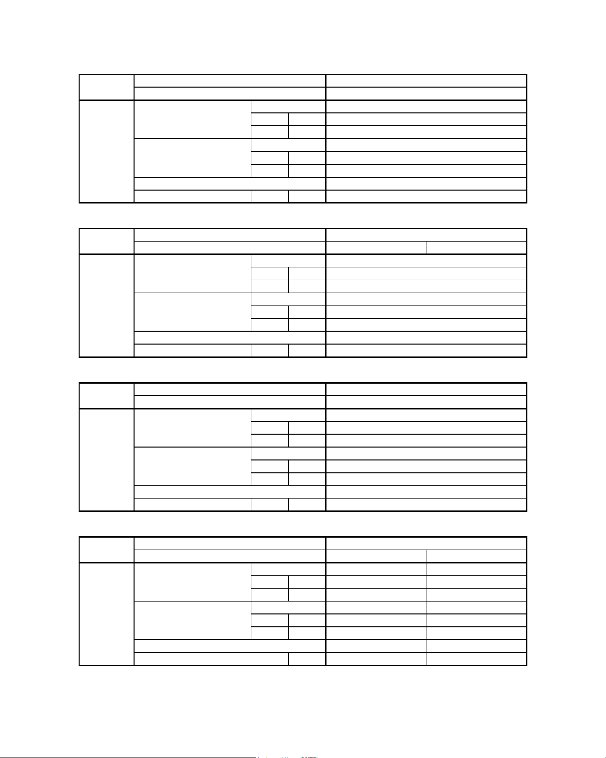
59
SAFETY DEVICES
1) ALL SPECIFICATIONS ARE SUBJECTED TO CHANGE BY THE MANUFACTURER WITHOUT PRIOR NOTICE.
OPEN kPa / psi
CLOSE kPa / psi
OPEN kPa / psi
CLOSE kPa / psi
DISCHARGE THERMOSTAT SETTING °C / °F
ALC 1 8C ALC 20C
OPEN kPa / psi
CLOSE kPa / psi
OPEN kPa / psi
CLOSE kPa / psi
DISCHARGE THERMOSTAT SETTING °C / °F
OPEN kPa / psi
CLOSE kPa / psi
OPEN kPa / psi
CLOSE kPa / psi
DISCHARGE THERMOSTAT SETTING °C / °F
ALC 2 8C ALC 30C
N/A NC
OPEN kPa / psi N/A 2937 / 426
CLOSE kPa / psi N/A 2413 / 350
N/A NC
OPEN kPa / psi N/A 124 / 18
CLOSE kPa / psi N/A 193 / 28
N/A N/A / <YES>
DISCHARGE THERMOSTAT SETTING - 1Ø / <3Ø> °C / °F N/A N/A / <130 / 266>
ACM 2 8E
OUTDOOR UNIT
TYPE
TYPE
TYPE
TYPE
HIGH PRESSURE SW ITCH
LOW PRESSURE SWITCH
N/A
N/A
SAFETY DEVICE
HIGH PRESSURE SW ITCH
LOW PRESSURE SWITCH
PHASE SEQUENCER - 1Ø / <3Ø>
TYPE
TYPE
OUTDOOR UNIT
PHASE SEQUENCER
MODEL
INDOOR UNIT
SAFETY DEVICE
HIGH PRESSURE SW ITCH
LOW PRESSURE SWITCH
PHASE SEQUENCER
MODEL
INDOOR UNIT
N/A
N/A
ACM 1 5E
MODEL
INDOOR UNIT ACM 2 5E
OUTDOOR UNIT
MODEL
SAFETY DEVICE
INDOOR UNIT
N/A
N/A
N/A
N/A
ALC 1 5C
ALC 2 5C
N/A
N/A
N/A
N/A
N/A
N/A
N/A
N/A
SAFETY DEVICE
HIGH PRESSURE SW ITCH
TYPE N/A
N/A
N/A
LOW PRESSURE SWITCH
TYPE
PHASE SEQUENCER N/A
ACM 2 0E
OUTDOOR UNIT
N/A
N/A
N/A
N/A
Page 62

60
SAFETY DEVICES
1) ALL SPECIFICATIONS ARE SUBJECTED TO CHANGE BY THE MANUFACTURER WITHOUT PRIOR NOTICE.
OPEN kPa / psi
CLOSE kPa / psi
OPEN kPa / psi
CLOSE kPa / psi
DISCHARGE THERMOSTAT SETTING °C / °F
ALC 18CR ALC 20CR
OPEN kPa / psi
CLOSE kPa / psi
OPEN kPa / psi
CLOSE kPa / psi
DISCHARGE THERMOSTAT SETTING °C / °F
OPEN kPa / psi
CLOSE kPa / psi
OPEN kPa / psi
CLOSE kPa / psi
DISCHARGE THERMOSTAT SETTING °C / °F
ALC 28CR ALC 30CR
N/A NC
OPEN kPa / psi N/A 2937 / 426
CLOSE kPa / psi N/A 2413 / 350
N/A N/A
OPEN kPa / psi N/A N/A
CLOSE kPa / psi N/A N/A
N/A N/A / <YES>
DISCHARGE THERMOSTAT SETTING - 1Ø / <3Ø> °C / °F N/A N/A / <130 / 266>
MODEL
INDOOR UNIT
MODEL
SAFETY DEVICE
INDOOR UNIT
OUTDOOR UNIT
PHASE SEQUENCER
PHASE SEQUENCER
LOW PRESSURE SWITCH
TYPE
SAFETY DEVICE
HIGH PRESSURE SW ITCH
LOW PRESSURE SWITCH
PHASE SEQUENCER
TYPE
TYPE
OUTDOOR UNIT
ACM 2 5ER
OUTDOOR UNIT
TYPE
TYPE
HIGH PRESSURE SW ITCH
LOW PRESSURE SWITCH
N/A
N/A
N/A
N/A
SAFETY DEVICE
HIGH PRESSURE SW ITCH
TYPE
LOW PRESSURE SWITCH
TYPE
PHASE SEQUENCER - 1Ø / <3Ø>
MODEL
INDOOR UNIT ACM 2 8ER
N/A
N/A
N/A
N/A
N/A
N/A
N/A
SAFETY DEVICE
HIGH PRESSURE SW ITCH
TYPE N/A
N/A
N/A
N/A
N/A
ACM 1 5ER
MODEL
INDOOR UNIT ACM 2 0ER
OUTDOOR UNIT
ALC 25CR
N/A
ALC 15CR
N/A
N/A
N/A
N/A
N/A
N/A
N/A
Page 63

61
SAFETY DEVICES
1) ALL SPECIFICATIONS ARE SUBJECTED TO CHANGE BY THE MANUFACTURER WITHOUT PRIOR NOTICE.
OPEN kPa / psi
CLOSE kPa / psi
OPEN kPa / psi
CLOSE kPa / psi
DISCHARGE THERMOSTAT SETTING °C / °F
OPEN kPa / psi
CLOSE kPa / psi
OPEN kPa / psi
CLOSE kPa / psi
DISCHARGE THERMOSTAT SETTING - 1Ø / <3Ø> °C / °F
OPEN kPa / psi
CLOSE kPa / psi
OPEN kPa / psi
CLOSE kPa / psi
DISCHARGE THERMOSTAT SETTING - 1Ø / <3Ø> °C / °F
A5LC 28C A5LC 35C
N/A NC
OPEN kPa / psi N/A 4140 / 600
CLOSE kPa / psi N/A 3312 / 480
N/A NC
OPEN kPa / psi N/A 48 / 7
CLOSE kPa / psi N/A 152 / 22
N/A / <YES> N/A / <YES>
DISCHARGE THERMOSTAT SETTING - 1Ø / <3Ø> °C / °F N/A / <130 / 266> N/A / <130 / 266>
N/A
N/A
A5LC 20C
N/A / <YES>
N/A
N/A
N/A
A5CM 20E
OUTDOOR UNIT
SAFETY DEVICE
HIGH PRESSURE SW ITCH
TYPE
LOW PRESSURE SWITCH
TYPE
PHASE SEQUENCER - 1Ø / <3Ø>
N/A / <130 / 266>
N/A
A5LC 15C
A5LC 25C
N/A / <YES>
N/A
N/A
N/A
N/A
N/A
N/A
N/A
N/A / <130 / 266>
N/A
N/A
N/A
N/A
N/A
A5CM 15E
MODEL
INDOOR UNIT A5 CM 2 5E
OUTDOOR UNIT
MODEL
SAFETY DEVICE
INDOOR UNIT
OUTDOOR UNIT
PHASE SEQUENCER
MODEL
INDOOR UNIT
SAFETY DEVICE
HIGH PRESSURE SW ITCH
LOW PRESSURE SWITCH
PHASE SEQUENCER - 1Ø / <3Ø>
MODEL
INDOOR UNIT
SAFETY DEVICE
HIGH PRESSURE SW ITCH
LOW PRESSURE SWITCH
PHASE SEQUENCER - 1Ø / <3Ø>
TYPE
TYPE
A5CM 28E
OUTDOOR UNIT
TYPE
TYPE
TYPE
TYPE
HIGH PRESSURE SW ITCH
LOW PRESSURE SWITCH
N/A
N/A
Page 64

62
SAFETY DEVICES
1) ALL SPECIFICATIONS ARE SUBJECTED TO CHANGE BY THE MANUFACTURER WITHOUT PRIOR NOTICE.
OPEN kPa / psi
CLOSE kPa / psi
OPEN kPa / psi
CLOSE kPa / psi
DISCHARGE THERMOSTAT SETTING °C / °F
OPEN kPa / psi
CLOSE kPa / psi
OPEN kPa / psi
CLOSE kPa / psi
DISCHARGE THERMOSTAT SETTING - 1Ø / <3Ø> °C / °F
OPEN kPa / psi
CLOSE kPa / psi
OPEN kPa / psi
CLOSE kPa / psi
DISCHARGE THERMOSTAT SETTING - 1Ø / <3Ø> °C / °F
A5LC 28CR A5LC 35CR
N/A NC
OPEN kPa / psi N/A 4140 / 600
CLOSE kPa / psi N/A 3312 / 480
N/A NC
OPEN kPa / psi N/A 48 / 7
CLOSE kPa / psi N/A 152 / 22
N/A / <YES> N/A / <YES>
DISCHARGE THERMOSTAT SETTING - 1Ø / <3Ø> °C / °F N/A / <130 / 266> N/A / <130 / 266>
N/A
N/A
A5LC 20CR
N/A / <YES>
N/A
N/A
N/A
A5CM 28ER
OUTDOOR UNIT
TYPE
TYPE
TYPE
TYPE
HIGH PRESSURE SW ITCH
LOW PRESSURE SWITCH
N/A
N/A
SAFETY DEVICE
HIGH PRESSURE SW ITCH
LOW PRESSURE SWITCH
PHASE SEQUENCER - 1Ø / <3Ø>
TYPE
TYPE
OUTDOOR UNIT
PHASE SEQUENCER
MODEL
INDOOR UNIT
SAFETY DEVICE
HIGH PRESSURE SW ITCH
LOW PRESSURE SWITCH
PHASE SEQUENCER - 1Ø / <3Ø>
MODEL
INDOOR UNIT
N/A
N/A
A5CM 15ER
MODEL
INDOOR UNIT A5CM 25ER
OUTDOOR UNIT
MODEL
SAFETY DEVICE
INDOOR UNIT
N/A / <130 / 266>
N/A
N/A
N/A
A5LC 15CR
A5LC 25CR
N/A / <YES>
N/A
N/A
N/A
N/A
N/A
N/A
N/A
A5CM 20ER
OUTDOOR UNIT
SAFETY DEVICE
HIGH PRESSURE SW ITCH
TYPE
LOW PRESSURE SWITCH
TYPE
PHASE SEQUENCER - 1Ø / <3Ø>
N/A / <130 / 266>
N/A
Page 65

6. PERFORMANCE DATA
Interpolation and Extrapolation method can be used to get the total capacity, Q and sensible capacity, SC at
those temperatures which are not stated out in the table.
Example:
Model: ACM 15E / ALC 15C
Indoor Condition: 23°C DB, 15°C WB
Outdoor Condition: 37°C DB
Solution:
Overall
Based on the Performance table in page 67,
1. Refer to the Indoor DB column,
- 23°C is located between 20°C and 24°C (Thus, Interpolation need to be applied)
2. Refer to the Indoor WB column,
- 15°C only available in the case of Indoor DB = 20°C. (Thus, Extrapolation between 16°C WB
and 17°C WB during 24°C indoor DB is required)
3. Refer to the Outdoor DB column,
- 37°C is located between 35°C and 40°C. (Thus, Interpolation need to be applied)
Please follow the steps below in order to get the required capacity.
1st Step
Extrapolation of Indoor WB
Find TC, SC for
(a) Indoor : 24°C DB, 15°C WB
Outdoor : 35°C DB
(b) Indoor : 24°C DB, 15°C WB
Outdoor : 40°C DB
2nd Step
Interpolation of Indoor DB
Find TC, SC for
(a) Indoor : 23°C DB, 15°C WB
Outdoor : 35°C DB
(b) Indoor : 23°C DB, 15°C WB
Outdoor : 40°C DB
3rd Step
Interpolation of Outdoor DB
Find TC, SC for
(a) Indoor : 23°C DB, 15°C WB
Outdoor : 37°C DB
63
Page 66

Details:
1st Step:
To obtain the Total capacity and Sensible capacity for
(a) Indoor Condition: 24°C DB, 15°C WB
Outdoor Condition: 35°C DB
Outdoor DB ° C
Indoor DB Indoor WB 35
° C ° C TC (kW) SC (kW)
15 x
1
y
1
24 16 3.363 2.381
17 3.431 2.288
Total capacity, TC
x1 = 3.295kW (Same as Total capacity at 20°C Indoor DB / 15°C Indoor WB & 35°C Outdoor WB)*
⇒
Sensible capacity, SC
Extrapolation Method:
17°C - 15°C
⇒
2.288kW - y
=
1
17°C - 16°C 2.288kW - 2.381kW
⇒ y1 = 2.474kW
(b) Indoor Condition: 24°C DB, 15°C WB
Outdoor Condition: 40°C DB
Outdoor DB ° C
Indoor DB Indoor WB 40
° C ° C TC (kW) SC (kW)
15 x
2
y
2
24 16 3.066 2.056
17 3.137 1.954
Total capacity, TC
x2 = 2.995kW (Same as Total capacity at 20°C Indoor DB / 15°C Indoor WB & 40°C Outdoor WB)*
⇒
Sensible capacity, SC
Extrapolation Method:
⇒
17°C - 15°C
1.954kW - y
=
2
17°C - 16°C 1.954kW - 2.056kW
⇒ y2 = 2.158kW
* This is due to 2 different conditions with same WB temperature, will have the same level of enthalpy. For
more details, please refer to psychrometrics chart
64
Page 67

2nd Step:
To obtain the Total capacity and Sensible capacity for
(a) Indoor Condition: 23°C DB, 15°C WB
Outdoor Condition: 35°C DB
Outdoor DB ° C
Indoor DB Indoor WB 35
° C ° C TC (kW) SC (kW)
20 15 3.295 1.510
23 15 x
3
y
3
24 15 3.295 2.474
Total capacity, TC
x3 = 3.295kW (Same as Total capacity at 20°C Indoor DB / 15°C Indoor WB & 35°C Outdoor WB)*
⇒
Sensible capacity, SC
Interpolation Method:
⇒
24°C - 20°C = 2.474kW - 1.510kW
24°C - 23°C 2.474kW - y
3
⇒ y3 = 2.233kW
(b) Indoor Condition: 23°C DB, 15°C WB
Outdoor Condition: 40°C DB
Outdoor DB ° C
Indoor DB Indoor WB 40
° C ° C TC (kW) SC (kW)
20 15 2.995 1.195
23 15 x
4
y
4
24 15 2.995 2.158
Total capacity, TC
x4 = 2.995kW (Same as Total capacity at 20°C Indoor DB / 15°C Indoor WB & 40°C Outdoor WB)*
⇒
Sensible capacity, SC
Interpolation Method:
24°C - 20°C = 2.158kW - 1.195kW
⇒
24°C - 23°C 2.158kW - y
4
⇒ y4 = 1.917kW
* This is due to 2 different conditions with same WB temperature will have the same level of enthalpy. For
more details, please refer to psychrometrics chart
65
Page 68

3rd Step:
To obtain the Total capacity and Sensible capacity for
(a) Indoor Condition: 23°C DB, 15°C WB
Outdoor Condition: 37°C DB
Outdoor DB ° C
Indoor DB Indoor WB 35 37 40
° C ° C TC (kW) SC (kW) TC (kW) SC (kW) TC (kW) SC (kW)
23 15 3.295 2.233 xy2.995 1.917
Total capacity, TC
Interpolation Method:
40°C - 35°C = 2.995kW - 3.295kW
⇒
40°C - 37°C 2.995kW - x
⇒ x = 3.175kW
Sensible capacity, SC
Interpolation Method:
40°C - 35°C = 1.917kW - 2.233kW
⇒
40°C - 37°C 1.917kW - y
⇒ y = 2.107kW
66
Page 69

67
Performance Tables
R22 MODELS
(COOLING ONLY)
MODEL : ACM 15E / ALC 15C
MODEL : ACM 20E / ALC 18C
TC(kW) SC(kW) TC(kW) SC(kW) TC(kW) SC(kW) TC(kW) SC(kW) TC(kW) SC(kW) TC(kW) SC(kW)
15
4.198 2.455 3.897 2.140 3.596 1.825 3 295 1.510 2.995 1.195 2.634 0.816
16
4 255 2.390 3.958 2 065 3.660 1.741 3 363 1.417 3.066 1 093 2.709 0.704
16
4 255 3.353 3.958 3 029 3.660 2.705 3 363 2.381 3.066 2 056 2.709 1.667
17
4 313 3.288 4.019 2 955 3.725 2.621 3.431 2.288 3.137 1 954 2.784 1.554
18
4 370 3.224 4.080 2 881 3.789 2.538 3.498 2.195 3.208 1 853 2.859 1.441
19
4.428 3.159 4.140 2 807 3.853 2.455 3 566 2.103 3.279 1.751 2.934 1.328
20
4.486 3.095 4.207 2.744 3.928 2.393 3 649 2.042 3.370 1 691 3.036 1.270
18
4 370 4.187 4.080 3 844 3.789 3.502 3.498 3.159 3.208 2 816 2.859 2.405
19
4.428 4.122 4.140 3.770 3.853 3.418 3 566 3.066 3.279 2.714 2.934 2.292
20
4.486 4.059 4.207 3.708 3.928 3.357 3 649 3.006 3.370 2 655 3.036 2.234
21
4 544 3.996 4.277 3 653 4.010 3.310 3.742 2.967 3.475 2 624 3.154 2.213
22
4 603 3.933 4.347 3 598 4.091 3.263 3 836 2.928 3.580 2 593 3.273 2.192
23
4 661 3.870 4.417 3 543 4.173 3.216 3 929 2.890 3.685 2 563 3.392 2.170
24
4.720 3.807 4.487 3.489 4.255 3.170 4 022 2.851 3.790 2 532 3.511 2.149
20
4 540 4.540 4.207 4.190 3.928 3.839 3 649 3.488 3.370 3.137 3.036 2.716
21
4 544 4.478 4.277 4.135 4.010 3.792 3.742 3.449 3.475 3.106 3.154 2.695
22
4 603 4.415 4.347 4 080 4.091 3.745 3 836 3.410 3.580 3 075 3.273 2.673
23
4 661 4.352 4.417 4 025 4.173 3.698 3 929 3.371 3.685 3 044 3.392 2.652
24
4.720 4.289 4.487 3 970 4.255 3.651 4 022 3.333 3.790 3 014 3.511 2.631
20
24
28
30
ID DB°C ID WB°C
Outdoor DB°C
20 25 30 35 40 46
TC(kW) SC(kW) TC(kW) SC(kW) TC(kW) SC(kW) TC(kW) SC(kW) TC(kW) SC(kW) TC(kW) SC(kW)
15
5.742 3.706 5.396 3.412 5.049 3.117 4.702 2.822 4.355 2 528 3.939 2.174
16
5 967 3.456 5.597 3.186 5.227 2.916 4 857 2.646 4.487 2 376 4.043 2.052
16
5 967 4.367 5.597 4 097 5.227 3.827 4 857 3.557 4.487 3 287 4.043 2.963
17
6.192 4.116 5.799 3 871 5.406 3.626 5 013 3.381 4.620 3.136 4.148 2.842
18
6.417 3.866 6.001 3 645 5.585 3.425 5.168 3.205 4.752 2 985 4.252 2.720
19
6 643 3.615 6.203 3.420 5.763 3.224 5 324 3.029 4.884 2 833 4.357 2.599
20
6 869 3.364 6.415 3.189 5.962 3.013 5 509 2.838 5.055 2 663 4.511 2.453
18
6.417 4.776 6.001 4 556 5.585 4.336 5.168 4.116 4.752 3 895 4.252 3.631
19
6 643 4.526 6.203 4 330 5.763 4.135 5 324 3.940 4.884 3.744 4.357 3.510
20
6 869 4.275 6.415 4 099 5.962 3.924 5 509 3.749 5.055 3 574 4.511 3.363
21
7 096 4.023 6.635 3 865 6.174 3.707 5.713 3.549 5.252 3 390 4.699 3.200
22
7 323 3.772 6.854 3 631 6.386 3.489 5 917 3.348 5.449 3 207 4.887 3.037
23
7 549 3.520 7.073 3 396 6.598 3.272 6.122 3.148 5.646 3 023 5.074 2.874
24
7.776 3.269 7.293 3.162 6.809 3.055 6 326 2.947 5.842 2 840 5.262 2.711
20
6 869 4.730 6.415 4 555 5.962 4.380 5 509 4.204 5.055 4 029 4.511 3.819
21
7 096 4.479 6.635 4 320 6.174 4.162 5.713 4.004 5.252 3 846 4.699 3.656
22
7 323 4.227 6.854 4 086 6.386 3.945 5 917 3.803 5.449 3 662 4.887 3.493
23
7 549 3.976 7.073 3 852 6.598 3.727 6.122 3.603 5.646 3.479 5.074 3.330
24
7.776 3.724 7.293 3 617 6.809 3.510 6 326 3.403 5.842 3 295 5.262 3.167
20
24
28
30
ID DB°C ID WB°C
Outdoor DB°C
20 25 30 35 40 46
Page 70

68
R22 MODELS
(COOLING ONLY)
MODEL : ACM 20E / ALC 20C
MODEL : ACM 25E / ALC 25C
TC(kW) SC(kW) TC(kW) SC(kW) TC(kW) SC(kW) TC(kW) SC(kW) TC(kW) SC(kW) TC(kW) SC(kW)
15
5 850 3.645 5.531 3 384 5.213 3.123 4 894 2.862 4.575 2 602 4.193 2.288
16
6 081 3.339 5.746 3.114 5.410 2.889 5 074 2.664 4.738 2.439 4.335 2.169
16
6 081 4.310 5.746 4 085 5.410 3.860 5 074 3.635 4.738 3.410 4.335 3.140
17
6 313 4.004 5.960 3 814 5.607 3.625 5 254 3.436 4.900 3 247 4.477 3.020
18
6 544 3.697 6.174 3 544 5.804 3.391 5.433 3.238 5.063 3 085 4.619 2.901
19
6.776 3.391 6.388 3 274 6.001 3.157 5 613 3.039 5.226 2 922 4.761 2.781
20
7 008 3.084 6.605 2 993 6.202 2.902 5 800 2.811 5.397 2.720 4.914 2.610
18
6 544 4.668 6.174 4 515 5.804 4.362 5.433 4.209 5.063 4 055 4.619 3.872
19
6.776 4.362 6.388 4 245 6.001 4.127 5 613 4.010 5.226 3 893 4.761 3.752
20
7 008 4.054 6.605 3 963 6.202 3.872 5 800 3.781 5.397 3 690 4.914 3.581
21
7 240 3.746 6.823 3 675 6.407 3.604 5 990 3.532 5.574 3.461 5.074 3.376
22
7.472 3.438 7.041 3 386 6.611 3.335 6.181 3.284 5.750 3 232 5.234 3.170
23
7.703 3.130 7.259 3 098 6.815 3.066 6 371 3.035 5.927 3 003 5.394 2.965
24
7 935 2.822 7.477 2 810 7.020 2.798 6 562 2.786 6.104 2.774 5.554 2.759
20
7 008 4.540 6.605 4.449 6.202 4.358 5 800 4.267 5.397 4.176 4.914 4.067
21
7 240 4.232 6.823 4.160 6.407 4.089 5 990 4.018 5.574 3 947 5.074 3.861
22
7.472 3.923 7.041 3 872 6.611 3.820 6.181 3.769 5.750 3.717 5.234 3.656
23
7.703 3.615 7.259 3 583 6.815 3.552 6 371 3.520 5.927 3.488 5.394 3.450
24
7 935 3.307 7.477 3 295 7.020 3.283 6 562 3.271 6.104 3 259 5.554 3.245
ID DB°C ID WB°C
Outdoor DB°C
20 25 30 35 40 46
20
24
28
30
TC(kW) SC(kW) TC(kW) SC(kW) TC(kW) SC(kW) TC(kW) SC(kW) TC(kW) SC(kW) TC(kW) SC(kW)
15
7 548 5.116 7.125 4.731 6.702 4.345 6 278 3.960 5.855 3 574 5.347 3.112
16
7.724 4.701 7.311 4 360 6.897 4.019 6.484 3.678 6.070 3 336 5.573 2.927
16
7.724 5.768 7.311 5.427 6.897 5.086 6.484 4.745 6.070 4.404 5.573 3.994
17
7 900 5.353 7.497 5 056 7.093 4.759 6 689 4.462 6.285 4.166 5.800 3.810
18
8 077 4.937 7.682 4 685 7.288 4.433 6 894 4.180 6.499 3 928 6.026 3.625
19
8 253 4.522 7.868 4 314 7.483 4.106 7 099 3.898 6.714 3 690 6.252 3.441
20
8.428 4.106 8.044 3 938 7.660 3.769 7 275 3.601 6.891 3.433 6.431 3.231
18
8 077 6.004 7.682 5.752 7.288 5.500 6 894 5.247 6.499 4 995 6.026 4.692
19
8 253 5.589 7.868 5 381 7.483 5.173 7 099 4.965 6.714 4.757 6.252 4.508
20
8.428 5.173 8.044 5 005 7.660 4.837 7 275 4.668 6.891 4 500 6.431 4.298
21
8 602 4.757 8.212 4 625 7.823 4.493 7.434 4.362 7.044 4 230 6.577 4.072
22
8.776 4.340 8.381 4 245 7.986 4.150 7 592 4.055 7.197 3 960 6.723 3.845
23
8 950 3.924 8.550 3 865 8.150 3.807 7.750 3.748 7.350 3 689 6.869 3.619
24
9.125 3.508 8.719 3.486 8.313 3.463 7 908 3.441 7.502 3.419 7.015 3.393
20
8.428 5.707 8.044 5 538 7.660 5.370 7 275 5.202 6.891 5 034 6.431 4.832
21
8 602 5.290 8.212 5.159 7.823 5.027 7.434 4.895 7.044 4.763 6.577 4.605
22
8.776 4.874 8.381 4.779 7.986 4.684 7 592 4.588 7.197 4.493 6.723 4.379
23
8 950 4.458 8.550 4 399 8.150 4.340 7.750 4.282 7.350 4 223 6.869 4.153
24
9.125 4.041 8.719 4 019 8.313 3.997 7 908 3.975 7.502 3 953 7.015 3.926
ID DB°C ID WB°C
Outdoor DB°C
20 25 30 35 40 46
20
24
28
30
Page 71

69
R22 MODELS
(COOLING ONLY)
MODEL : ACM 28E / ALC 28C
MODEL : ACM 28E / ALC 30C
TC(kW) SC(kW) TC(kW) SC(kW) TC(kW) SC(kW) TC(kW) SC(kW) TC(kW) SC(kW) TC(kW) SC(kW)
15
8 627 5.602 8.148 5 215 7.669 4.828 7.190 4.441 6.711 4 054 6.136 3.589
16
9 034 5.190 8.509 4 841 7.985 4.492 7.460 4.142 6.935 3.793 6.306 3.374
16
9 034 6.458 8.509 6.109 7.985 5.760 7.460 5.410 6.935 5 061 6.306 4.642
17
9.442 6.047 8.871 5.735 8.301 5.423 7.730 5.112 7.160 4 800 6.475 4.426
18
9 849 5.635 9.233 5 361 8.617 5.087 8 001 4.813 7.385 4 540 6.645 4.211
19
10.256 5.223 9.595 4 987 8.933 4.751 8 271 4.515 7.609 4 279 6.815 3.996
20
10.665 4.811 9.971 4 607 9.276 4.403 8 581 4.200 7.887 3 996 7.053 3.751
18
9 849 6.903 9.233 6 629 8.617 6.355 8 001 6.081 7.385 5 807 6.645 5.479
19
10.256 6.491 9.595 6 255 8.933 6.019 8 271 5.783 7.609 5 547 6.815 5.264
20
10.665 6.078 9.971 5 875 9.276 5.671 8 581 5.467 7.887 5 264 7.053 5.019
21
11.075 5.666 10.356 5.491 9.637 5.315 8 918 5.140 8.199 4 965 7.336 4.755
22
11.485 5.253 10.742 5.106 9.999 4.960 9 255 4.813 8.512 4 667 7.620 4.491
23
11.895 4.840 11.128 4.722 10 360 4.604 9 592 4.486 8.824 4 368 7.903 4.226
24
12.305 4.427 11.513 4 338 10.721 4.248 9 929 4.159 9.137 4 069 8.186 3.962
20
10.665 6.712 9.971 6 509 9.276 6.305 8 581 6.101 7.887 5 897 7.053 5.653
21
11.075 6.300 10.356 6.124 9.637 5.949 8 918 5.774 8.199 5 599 7.336 5.389
22
11.485 5.887 10.742 5.740 9.999 5.594 9 255 5.447 8.512 5 300 7.620 5.124
23
11.895 5.474 11.128 5 356 10 360 5.238 9 592 5.120 8.824 5 002 7.903 4.860
24
12.305 5.061 11.513 4 972 10.721 4.882 9 929 4.793 9.137 4.703 8.186 4.596
ID DB°C ID WB°C
Outdoor DB°C
20 25 30 35 40 46
20
24
28
30
TC(kW) SC(kW) TC(kW) SC(kW) TC(kW) SC(kW) TC(kW) SC(kW) TC(kW) SC(kW) TC(kW) SC(kW)
15
8 897 5.879 8.367 5.441 7.837 5.003 7 307 4.564 6.778 4.126 6.142 3.600
16
9 245 5.407 8.681 5 018 8.117 4.629 7 553 4.240 6.989 3 851 6.312 3.385
16
9 245 6.675 8.681 6 286 8.117 5.897 7 553 5.508 6.989 5.119 6.312 4.653
17
9 594 6.203 8.995 5 863 8.397 5.524 7.798 5.184 7.200 4 844 6.482 4.437
18
9 942 5.731 9.309 5.441 8.677 5.150 8 044 4.860 7.411 4 570 6.652 4.221
19
10.290 5.259 9.623 5 018 8.956 4.777 8 289 4.536 7.622 4 295 6.822 4.006
20
10.640 4.786 9.952 4 589 9.263 4.392 8 575 4.195 7.886 3 997 7.060 3.761
18
9 942 6.999 9.309 6.708 8.677 6.418 8 044 6.128 7.411 5 837 6.652 5.489
19
10.290 6.527 9.623 6 286 8.956 6.045 8 289 5.804 7.622 5 563 6.822 5.273
20
10.640 6.054 9.952 5 857 9.263 5.660 8 575 5.462 7.886 5 265 7.060 5.028
21
10.992 5.581 10.290 5.424 9.588 5.267 8 887 5.109 8.185 4 952 7.344 4.764
22
11.343 5.108 10.628 4 991 9.914 4.874 9.199 4.757 8.485 4 639 7.627 4.499
23
11.694 4.635 10.966 4 558 10 239 4.481 9 511 4.404 8.784 4 326 7.911 4.234
24
12.045 4.162 11.304 4.125 10 564 4.088 9 823 4.051 9.083 4 014 8.195 3.969
20
10.640 6.688 9.952 6.491 9.263 6.293 8 575 6.096 7.886 5 899 7.060 5.662
21
10.992 6.215 10.290 6 058 9.588 5.901 8 887 5.743 8.185 5 586 7.344 5.397
22
11.343 5.742 10.628 5 625 9.914 5.508 9.199 5.390 8.485 5 273 7.627 5.133
23
11.694 5.269 10.966 5.192 10 239 5.115 9 511 5.037 8.784 4 960 7.911 4.868
24
12.045 4.796 11.304 4.759 10 564 4.722 9 823 4.685 9.083 4 648 8.195 4.603
20
24
28
30
ID DB°C ID WB°C
Outdoor DB°C
20 25 30 35 40 46
Page 72

70
R22 MODELS
(HEATPUMP)
MODEL : ACM 15ER / ALC 15CR
COOLING MODE
HEATING MODE
TC(kW) SC(kW) TC(kW) SC(kW) TC(kW) SC(kW) TC(kW) SC(kW) TC(kW) SC(kW) TC(kW) SC(kW)
15
4.198 2.455 3.897 2.140 3.596 1.825 3 295 1.510 2.995 1.195 2.634 0.816
16
4 255 2.390 3.958 2 065 3.660 1.741 3 363 1.417 3.066 1 093 2.709 0.704
16
4 255 3.353 3.958 3 029 3.660 2.705 3 363 2.381 3.066 2 056 2.709 1.667
17
4 313 3.288 4.019 2 955 3.725 2.621 3.431 2.288 3.137 1 954 2.784 1.554
18
4 370 3.224 4.080 2 881 3.789 2.538 3.498 2.195 3.208 1 853 2.859 1.441
19
4.428 3.159 4.140 2 807 3.853 2.455 3 566 2.103 3.279 1.751 2.934 1.328
20
4.486 3.095 4.207 2.744 3.928 2.393 3 649 2.042 3.370 1 691 3.036 1.270
18
4 370 4.187 4.080 3 844 3.789 3.502 3.498 3.159 3.208 2 816 2.859 2.405
19
4.428 4.122 4.140 3.770 3.853 3.418 3 566 3.066 3.279 2.714 2.934 2.292
20
4.486 4.059 4.207 3.708 3.928 3.357 3 649 3.006 3.370 2 655 3.036 2.234
21
4 544 3.996 4.277 3 653 4.010 3.310 3.742 2.967 3.475 2 624 3.154 2.213
22
4 603 3.933 4.347 3 598 4.091 3.263 3 836 2.928 3.580 2 593 3.273 2.192
23
4 661 3.870 4.417 3 543 4.173 3.216 3 929 2.890 3.685 2 563 3.392 2.170
24
4.720 3.807 4.487 3.489 4.255 3.170 4 022 2.851 3.790 2 532 3.511 2.149
20
4 540 4.540 4.207 4.190 3.928 3.839 3 649 3.488 3.370 3.137 3.036 2.716
21
4 544 4.478 4.277 4.135 4.010 3.792 3.742 3.449 3.475 3.106 3.154 2.695
22
4 603 4.415 4.347 4 080 4.091 3.745 3 836 3.410 3.580 3 075 3.273 2.673
23
4 661 4.352 4.417 4 025 4.173 3.698 3 929 3.371 3.685 3 044 3.392 2.652
24
4.720 4.289 4.487 3 970 4.255 3.651 4 022 3.333 3.790 3 014 3.511 2.631
20
24
28
30
ID DB°C ID WB°C
Outdoor DB°C
20 25 30 35 40 46
TC(kW) SC(kW) TC(kW) SC(kW) TC(kW) SC(kW) TC(kW) SC(kW) TC(kW) SC(kW) TC(kW) SC(kW) TC(kW) SC(kW)
15
1.760 1.760 2.115 2.115 2.233 2.233 3.532 3 532 4 241 4.241 4.596 4.596 4.950 4 950
17 1.738 1.738 2 079 2 079 2.192 2.192 3.471 3.471 4.127 4.127 4.468 4.468 4.809 4 809
19
1.716 1.716 2 043 2 043 2.152 2.152 3.410 3.410 4 012 4.012 4.340 4.340 4.669 4 669
21 1.693 1.693 2 007 2 007 2.111 2.111 3.350 3 350 3 897 3.897 4.213 4.213 4.528 4 528
23 1.669 1.669 1 970 1 970 2.071 2.071 3.232 3 232 3.783 3.783 4.085 4.085 4.387 4 387
25
1.645 1.645 1 934 1 934 2.030 2.030 3.115 3.115 3 668 3.668 3.957 3.957 4.246 4 246
27 1.621 1.621 1 897 1 897 1.989 1.989 2.997 2 997 3 554 3.554 3.830 3.830 4.106 4.106
FROST REGION
ID DB°C
Outdoor WB°C
-9 -6 -5 6 12 15 18
Page 73

71
R22 MODELS
(HEATPUMP)
MODEL : ACM 20ER / ALC 18CR
COOLING MODE
HEATING MODE
TC(kW) SC(kW) TC(kW) SC(kW) TC(kW) SC(kW) TC(kW) SC(kW) TC(kW) SC(kW) TC(kW) SC(kW)
15
5.743 3.699 5.397 3.404 5.050 3.110 4.703 2.816 4.356 2 522 3.940 2.168
16
5 969 3.449 5.599 3.179 5.228 2.910 4 858 2.640 4.488 2 371 4.044 2.047
16
5 969 4.359 5.599 4 090 5.228 3.820 4 858 3.551 4.488 3 281 4.044 2.958
17
6.194 4.109 5.800 3 864 5.407 3.620 5 014 3.375 4.621 3.130 4.149 2.837
18
6.419 3.859 6.002 3 639 5.586 3.419 5.169 3.199 4.753 2 979 4.253 2.715
19
6 644 3.609 6.204 3.414 5.765 3.219 5 325 3.023 4.885 2 828 4.358 2.594
20
6 870 3.358 6.417 3.183 5.963 3.008 5 510 2.833 5.056 2 658 4.512 2.448
18
6.419 4.770 6.002 4 550 5.586 4.330 5.169 4.110 4.753 3 890 4.253 3.626
19
6 644 4.520 6.204 4 324 5.765 4.129 5 325 3.934 4.885 3.739 4.358 3.505
20
6 870 4.269 6.417 4 094 5.963 3.919 5 510 3.744 5.056 3 569 4.512 3.359
21
7 097 4.018 6.636 3 860 6.175 3.702 5.714 3.544 5.253 3 386 4.700 3.196
22
7 324 3.767 6.855 3 626 6.387 3.485 5 918 3.344 5.450 3 202 4.888 3.033
23
7 551 3.516 7.075 3 392 6.599 3.268 6.123 3.143 5.647 3 019 5.075 2.871
24
7.778 3.265 7.294 3.158 6.811 3.050 6 327 2.943 5.844 2 836 5.263 2.708
20
6 870 4.724 6.417 4 549 5.963 4.374 5 510 4.199 5.056 4 024 4.512 3.814
21
7 097 4.473 6.636 4 315 6.175 4.157 5.714 3.999 5.253 3 841 4.700 3.651
22
7 324 4.222 6.855 4 081 6.387 3.940 5 918 3.799 5.450 3 658 4.888 3.489
23
7 551 3.971 7.075 3 847 6.599 3.723 6.123 3.599 5.647 3.475 5.075 3.326
24
7.778 3.720 7.294 3 613 6.811 3.506 6 327 3.399 5.844 3 292 5.263 3.163
20
24
28
30
ID DB°C ID WB°C
Outdoor DB°C
20 25 30 35 40 46
TC(kW) SC(kW) TC(kW) SC(kW) TC(kW) SC(kW) TC(kW) SC(kW) TC(kW) SC(kW) TC(kW) SC(kW) TC(kW) SC(kW)
15
2.597 2.597 3.151 3.151 3.335 3.335 5.366 5 366 6.474 6.474 7.028 7.028 7.582 7 582
17
2.556 2.556 3 094 3 094 3.274 3.274 5.299 5 299 6 299 6.299 6.833 6.833 7.367 7 367
19
2.516 2.516 3 038 3 038 3.213 3.213 5.231 5 231 6.124 6.124 6.637 6.637 7.151 7.151
21 2.475 2.475 2 982 2 982 3.151 3.151 5.164 5.164 5 948 5.948 6.442 6.442 6.935 6 935
23 2.447 2.447 2 929 2 929 3.090 3.090 4.958 4 958 5.773 5.773 6.246 6.246 6.720 6.720
25 2.419 2.419 2 876 2 876 3.028 3.028 4.751 4.751 5 597 5.597 6.051 6.051 6.504 6 504
27
2.390 2.390 2 823 2 823 2.967 2.967 4.545 4 545 5.422 5.422 5.855 5.855 6.289 6 289
FROST REGION
ID DB°C
Outdoor WB°C
-9 -6 -5 6 12 15 18
Page 74

72
R22 MODELS
(HEATPUMP)
MODEL : ACM 20ER / ALC 20CR
COOLING MODE
HEATING MODE
TC(kW) SC(kW) TC(kW) SC(kW) TC(kW) SC(kW) TC(kW) SC(kW) TC(kW) SC(kW) TC(kW) SC(kW)
15
5 850 3.645 5.531 3 384 5.213 3.123 4 894 2.862 4.575 2 602 4.193 2.288
16
6 081 3.339 5.746 3.114 5.410 2.889 5 074 2.664 4.738 2.439 4.335 2.169
16
6 081 4.310 5.746 4 085 5.410 3.860 5 074 3.635 4.738 3.410 4.335 3.140
17
6 313 4.004 5.960 3 814 5.607 3.625 5 254 3.436 4.900 3 247 4.477 3.020
18
6 544 3.697 6.174 3 544 5.804 3.391 5.433 3.238 5.063 3 085 4.619 2.901
19
6.776 3.391 6.388 3 274 6.001 3.157 5 613 3.039 5.226 2 922 4.761 2.781
20
7 008 3.084 6.605 2 993 6.202 2.902 5 800 2.811 5.397 2.720 4.914 2.610
18
6 544 4.668 6.174 4 515 5.804 4.362 5.433 4.209 5.063 4 055 4.619 3.872
19
6.776 4.362 6.388 4 245 6.001 4.127 5 613 4.010 5.226 3 893 4.761 3.752
20
7 008 4.054 6.605 3 963 6.202 3.872 5 800 3.781 5.397 3 690 4.914 3.581
21
7 240 3.746 6.823 3 675 6.407 3.604 5 990 3.532 5.574 3.461 5.074 3.376
22
7.472 3.438 7.041 3 386 6.611 3.335 6.181 3.284 5.750 3 232 5.234 3.170
23
7.703 3.130 7.259 3 098 6.815 3.066 6 371 3.035 5.927 3 003 5.394 2.965
24
7 935 2.822 7.477 2 810 7.020 2.798 6 562 2.786 6.104 2.774 5.554 2.759
20
7 008 4.540 6.605 4.449 6.202 4.358 5 800 4.267 5.397 4.176 4.914 4.067
21
7 240 4.232 6.823 4.160 6.407 4.089 5 990 4.018 5.574 3 947 5.074 3.861
22
7.472 3.923 7.041 3 872 6.611 3.820 6.181 3.769 5.750 3.717 5.234 3.656
23
7.703 3.615 7.259 3 583 6.815 3.552 6 371 3.520 5.927 3.488 5.394 3.450
24
7 935 3.307 7.477 3 295 7.020 3.283 6 562 3.271 6.104 3 259 5.554 3.245
ID DB°C ID WB°C
Outdoor DB°C
20 25 30 35 40 46
20
24
28
30
TC(kW) SC(kW) TC(kW) SC(kW) TC(kW) SC(kW) TC(kW) SC(kW) TC(kW) SC(kW) TC(kW) SC(kW) TC(kW) SC(kW)
15
2.506 2.506 3.124 3.124 3.330 3.330 5.597 5 597 6 834 6.834 7.452 7.452 8 071 8 071
17
2.446 2.446 3 062 3.062 3.267 3.267 5.499 5.499 6 648 6.648 7.245 7.245 7 841 7 841
19
2.386 2.386 2 999 2.999 3.204 3.204 5.401 5.401 6.462 6.462 7.037 7.037 7 612 7 612
21
2.326 2.326 2 937 2.937 3.140 3.140 5.303 5 303 6 276 6.276 6.829 6.829 7 382 7 382
23
2.319 2.319 2 887 2.887 3.077 3.077 5.113 5.113 6 089 6.089 6.621 6.621 7.153 7.153
25
2.311 2.311 2 838 2.838 3.014 3.014 4.924 4 924 5 903 5.903 6.413 6.413 6 923 6 923
27
2.304 2.304 2.789 2.789 2.951 2.951 4.734 4.734 5.717 5.717 6.205 6.205 6 694 6 694
FROST REGION
ID DB°C
Outdoor WB°C
-9 -6 -5 6 12 15 18
Page 75

73
R22 MODELS
(HEATPUMP)
MODEL : ACM 25ER / ALC 25CR
COOLING MODE
HEATING MODE
TC(kW) SC(kW) TC(kW) SC(kW) TC(kW) SC(kW) TC(kW) SC(kW) TC(kW) SC(kW) TC(kW) SC(kW)
15
7 548 5.116 7.125 4.731 6.702 4.345 6 278 3.960 5.855 3 574 5.347 3.112
16
7.724 4.701 7.311 4 360 6.897 4.019 6.484 3.678 6.070 3 336 5.573 2.927
16
7.724 5.768 7.311 5.427 6.897 5.086 6.484 4.745 6.070 4.404 5.573 3.994
17
7 900 5.353 7.497 5 056 7.093 4.759 6 689 4.462 6.285 4.166 5.800 3.810
18
8 077 4.937 7.682 4 685 7.288 4.433 6 894 4.180 6.499 3 928 6.026 3.625
19
8 253 4.522 7.868 4 314 7.483 4.106 7 099 3.898 6.714 3 690 6.252 3.441
20
8.428 4.106 8.044 3 938 7.660 3.769 7 275 3.601 6.891 3.433 6.431 3.231
18
8 077 6.004 7.682 5.752 7.288 5.500 6 894 5.247 6.499 4 995 6.026 4.692
19
8 253 5.589 7.868 5 381 7.483 5.173 7 099 4.965 6.714 4.757 6.252 4.508
20
8.428 5.173 8.044 5 005 7.660 4.837 7 275 4.668 6.891 4 500 6.431 4.298
21
8 602 4.757 8.212 4 625 7.823 4.493 7.434 4.362 7.044 4 230 6.577 4.072
22
8.776 4.340 8.381 4 245 7.986 4.150 7 592 4.055 7.197 3 960 6.723 3.845
23
8 950 3.924 8.550 3 865 8.150 3.807 7.750 3.748 7.350 3 689 6.869 3.619
24
9.125 3.508 8.719 3.486 8.313 3.463 7 908 3.441 7.502 3.419 7.015 3.393
20
8.428 5.707 8.044 5 538 7.660 5.370 7 275 5.202 6.891 5 034 6.431 4.832
21
8 602 5.290 8.212 5.159 7.823 5.027 7.434 4.895 7.044 4.763 6.577 4.605
22
8.776 4.874 8.381 4.779 7.986 4.684 7 592 4.588 7.197 4.493 6.723 4.379
23
8 950 4.458 8.550 4 399 8.150 4.340 7.750 4.282 7.350 4 223 6.869 4.153
24
9.125 4.041 8.719 4 019 8.313 3.997 7 908 3.975 7.502 3 953 7.015 3.926
ID DB°C ID WB°C
Outdoor DB°C
20 25 30 35 40 46
20
24
28
30
TC(kW) SC(kW) TC(kW) SC(kW) TC(kW) SC(kW) TC(kW) SC(kW) TC(kW) SC(kW) TC(kW) SC(kW) TC(kW) SC(kW)
15
3.228 3.228 4 000 4.000 4.257 4.257 7.088 7 088 8 633 8.633 9.405 9.405 10.177 10.177
17
3.157 3.157 3 922 3.922 4.177 4.177 7.052 7 052 8 398 8.398 9.143 9.143 9 887 9 887
19
3.086 3.086 3 844 3.844 4.097 4.097 7.015 7 015 8.163 8.163 8.880 8.880 9 598 9 598
21
3.015 3.015 3.766 3.766 4.016 4.016 6.978 6 978 7 928 7.928 8.618 8.618 9 309 9 309
23
2.999 2.999 3.702 3.702 3.936 3.936 6.647 6 647 7 693 7.693 8.356 8.356 9 019 9 019
25
2.984 2.984 3 638 3.638 3.856 3.856 6.315 6 315 7.458 7.458 8.094 8.094 8.730 8.730
27
2.968 2.968 3 574 3.574 3.775 3.775 5.984 5 984 7 223 7.223 7.832 7.832 8.440 8.440
FROST REGION
ID DB°C
Outdoor WB°C
-9 -6 -5 6 12 15 18
Page 76

R22 MODELS
(HEATPUMP)
MODEL : ACM 28ER / ALC 28CR
COOLING MODE
HEATING MODE
TC(kW) SC(kW) TC(kW) SC(kW) TC(kW) SC(kW) TC(kW) SC(kW) TC(kW) SC(kW) TC(kW) SC(kW)
15
8 627 5.602 8.148 5 215 7.669 4.828 7.190 4.441 6.711 4 054 6.136 3.589
16
9 034 5.190 8.509 4 841 7.985 4.492 7.460 4.142 6.935 3.793 6.306 3.374
16
9 034 6.458 8.509 6.109 7.985 5.760 7.460 5.410 6.935 5 061 6.306 4.642
17
9.442 6.047 8.871 5.735 8.301 5.423 7.730 5.112 7.160 4 800 6.475 4.426
18
9 849 5.635 9.233 5 361 8.617 5.087 8 001 4.813 7.385 4 540 6.645 4.211
19
10.256 5.223 9.595 4 987 8.933 4.751 8 271 4.515 7.609 4 279 6.815 3.996
20
10.665 4.811 9.971 4 607 9.276 4.403 8 581 4.200 7.887 3 996 7.053 3.751
18
9 849 6.903 9.233 6 629 8.617 6.355 8 001 6.081 7.385 5 807 6.645 5.479
19
10.256 6.491 9.595 6 255 8.933 6.019 8 271 5.783 7.609 5 547 6.815 5.264
20
10.665 6.078 9.971 5 875 9.276 5.671 8 581 5.467 7.887 5 264 7.053 5.019
21
11.075 5.666 10.356 5.491 9.637 5.315 8 918 5.140 8.199 4 965 7.336 4.755
22
11.485 5.253 10.742 5.106 9.999 4.960 9 255 4.813 8.512 4 667 7.620 4.491
23
11.895 4.840 11.128 4.722 10 360 4.604 9 592 4.486 8.824 4 368 7.903 4.226
24
12.305 4.427 11.513 4 338 10.721 4.248 9 929 4.159 9.137 4 069 8.186 3.962
20
10.665 6.712 9.971 6 509 9.276 6.305 8 581 6.101 7.887 5 897 7.053 5.653
21
11.075 6.300 10.356 6.124 9.637 5.949 8 918 5.774 8.199 5 599 7.336 5.389
22
11.485 5.887 10.742 5.740 9.999 5.594 9 255 5.447 8.512 5 300 7.620 5.124
23
11.895 5.474 11.128 5 356 10 360 5.238 9 592 5.120 8.824 5 002 7.903 4.860
24
12.305 5.061 11.513 4 972 10.721 4.882 9 929 4.793 9.137 4.703 8.186 4.596
ID DB°C ID WB°C
Outdoor DB°C
20 25 30 35 40 46
20
24
28
30
TC(kW) SC(kW) TC(kW) SC(kW) TC(kW) SC(kW) TC(kW) SC(kW) TC(kW) SC(kW) TC(kW) SC(kW) TC(kW) SC(kW)
15 3.707 3.707 4 621 4 621 4.926 4.926 8.276 8 276 10.103 10.103 11 017 11.017 11.931 11.931
17 3.619 3.619 4 529 4 529 4.832 4.832 8.122 8.122 9 828 9.828 10.710 10.710 11.591 11.591
19 3.531 3.531 4.437 4.437 4.739 4.739 7.969 7 969 9 553 9.553 10.402 10.402 11.252 11.252
21
3.443 3.443 4 344 4 344 4.645 4.645 7.816 7 816 9 278 9.278 10 095 10.095 10.913 10.913
23
3.431 3.431 4 271 4 271 4.552 4.552 7.544 7 544 9 003 9.003 9.788 9.788 10.573 10.573
25
3.420 3.420 4.198 4.198 4.458 4.458 7.272 7 272 8.727 8.727 9.481 9.481 10.234 10.234
27
3.409 3.409 4.125 4.125 4.364 4.364 7.000 7 000 8.452 8.452 9.173 9.173 9.895 9 895
FROST REGION
ID DB°C
Outdoor WB°C
-9 -6 -5 6 12 15 18
74
Page 77

R22 MODELS
(HEATPUMP)
MODEL : ACM 28ER / ALC 30CR
COOLING MODE
HEATING MODE
75
TC(kW) SC(kW) TC(kW) SC(kW) TC(kW) SC(kW) TC(kW) SC(kW) TC(kW) SC(kW) TC(kW) SC(kW)
15
8 897 5.879 8.367 5.441 7.837 5.003 7 307 4.564 6.778 4.126 6.142 3.600
16
9 245 5.407 8.681 5 018 8.117 4.629 7 553 4.240 6.989 3 851 6.312 3.385
16
9 245 6.675 8.681 6 286 8.117 5.897 7 553 5.508 6.989 5.119 6.312 4.653
17
9 594 6.203 8.995 5 863 8.397 5.524 7.798 5.184 7.200 4 844 6.482 4.437
18
9 942 5.731 9.309 5.441 8.677 5.150 8 044 4.860 7.411 4 570 6.652 4.221
19
10.290 5.259 9.623 5 018 8.956 4.777 8 289 4.536 7.622 4 295 6.822 4.006
20
10.640 4.786 9.952 4 589 9.263 4.392 8 575 4.195 7.886 3 997 7.060 3.761
18
9 942 6.999 9.309 6.708 8.677 6.418 8 044 6.128 7.411 5 837 6.652 5.489
19
10.290 6.527 9.623 6 286 8.956 6.045 8 289 5.804 7.622 5 563 6.822 5.273
20
10.640 6.054 9.952 5 857 9.263 5.660 8 575 5.462 7.886 5 265 7.060 5.028
21
10.992 5.581 10.290 5.424 9.588 5.267 8 887 5.109 8.185 4 952 7.344 4.764
22
11.343 5.108 10.628 4 991 9.914 4.874 9.199 4.757 8.485 4 639 7.627 4.499
23
11.694 4.635 10.966 4 558 10 239 4.481 9 511 4.404 8.784 4 326 7.911 4.234
24
12.045 4.162 11.304 4.125 10 564 4.088 9 823 4.051 9.083 4 014 8.195 3.969
20
10.640 6.688 9.952 6.491 9.263 6.293 8 575 6.096 7.886 5 899 7.060 5.662
21
10.992 6.215 10.290 6 058 9.588 5.901 8 887 5.743 8.185 5 586 7.344 5.397
22
11.343 5.742 10.628 5 625 9.914 5.508 9.199 5.390 8.485 5 273 7.627 5.133
23
11.694 5.269 10.966 5.192 10 239 5.115 9 511 5.037 8.784 4 960 7.911 4.868
24
12.045 4.796 11.304 4.759 10 564 4.722 9 823 4.685 9.083 4 648 8.195 4.603
ID DB°C ID WB°C
Outdoor DB°C
20 25 30 35 40 46
20
24
28
30
TC(kW) SC(kW) TC(kW) SC(kW) TC(kW) SC(kW) TC(kW) SC(kW) TC(kW) SC(kW) TC(kW) SC(kW) TC(kW) SC(kW)
15
3.707 3.707 4 621 4.621 4.926 4.926 8.276 8 276 10.103 10.103 11.017 11.017 11.931 11.931
17
3.619 3.619 4 529 4.529 4.832 4.832 8.122 8.122 9 828 9.828 10.710 10.710 11.591 11.591
19
3.531 3.531 4.437 4.437 4.739 4.739 7.969 7 969 9 553 9.553 10.402 10.402 11.252 11.252
21
3.443 3.443 4 344 4.344 4.645 4.645 7.816 7 816 9 278 9.278 10.095 10.095 10.913 10.913
23
3.431 3.431 4 271 4.271 4.552 4.552 7.544 7 544 9 003 9.003 9.788 9.788 10.573 10.573
25
3.420 3.420 4.198 4.198 4.458 4.458 7.272 7 272 8.727 8.727 9.481 9.481 10.234 10.234
27
3.409 3.409 4.125 4.125 4.364 4.364 7.000 7 000 8.452 8.452 9.173 9.173 9 895 9 895
FROST REGION
ID DB°C
Outdoor WB°C
-9 -6 -5 6 12 15 18
Page 78
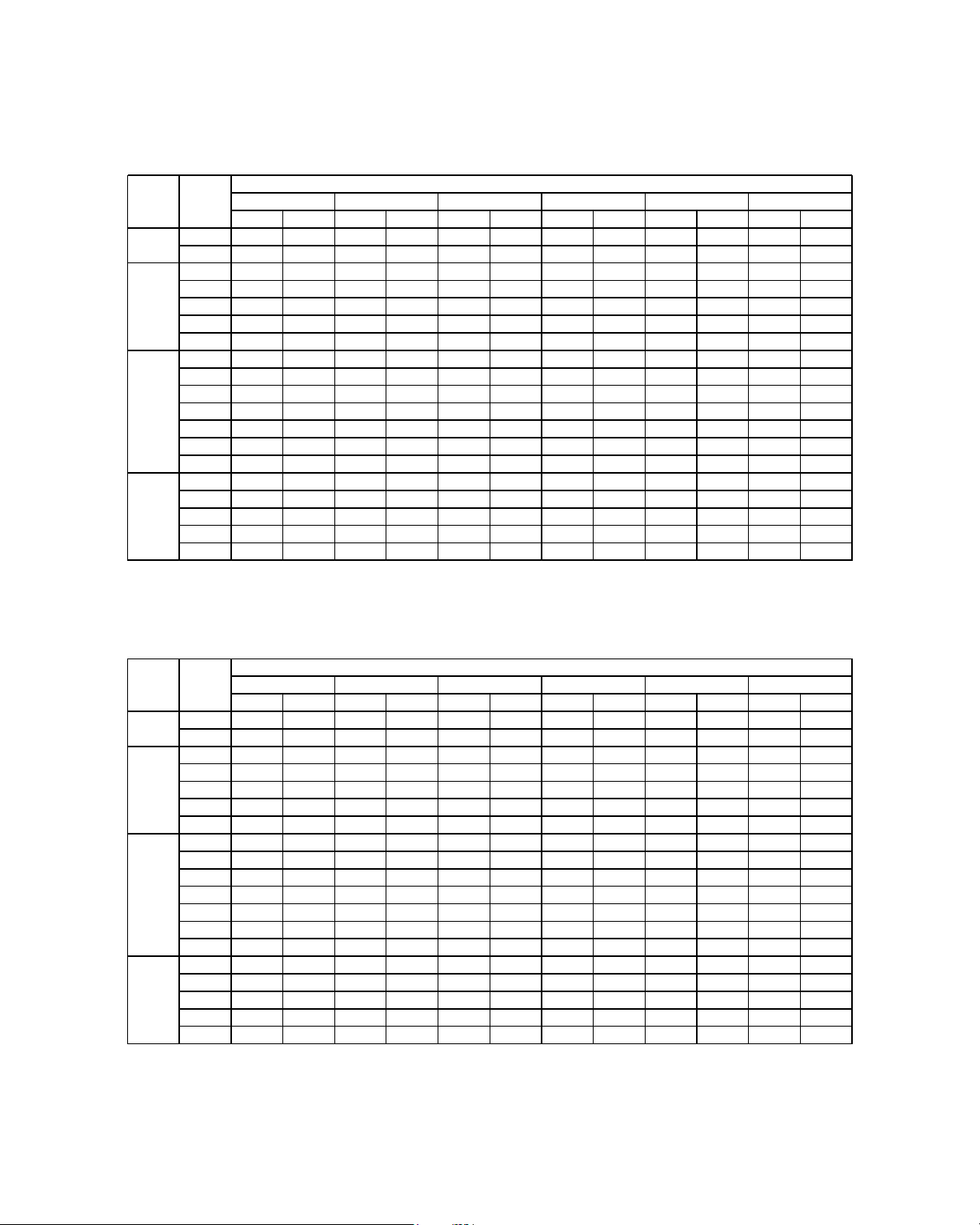
76
R410A MODELS
(COOLING ONLY)
MODEL : A5CM 15E / A5LC 15C
MODEL : A5CM 20E / A5LC 20C (1 PHASE)
TC(kW) SC(kW) TC(kW) SC(kW) TC(kW) SC(kW) TC(kW) SC(kW) TC(kW) SC(kW) TC(kW) SC(kW)
15
4 362 2.573 3.980 2.190 3.593 1.802 3 206 1.414 2.819 1 027 2.354 0.562
16
4.440 2.359 4.074 2 005 3.706 1.648 3 338 1.292 2.970 0 936 2.528 0.508
16
4.440 3.385 4.074 3 031 3.706 2.675 3 338 2.318 2.970 1 962 2.528 1.534
17
4 517 3.171 4.168 2 846 3.819 2.521 3.470 2.196 3.121 1 871 2.702 1.481
18
4 597 2.960 4.266 2 665 3.935 2.370 3 604 2.075 3.273 1.781 2.876 1.427
19
4 679 2.753 4.380 2 515 4.082 2.276 3.783 2.038 3.450 1.736 3.050 1.373
20
4.752 2.529 4.437 2 257 4.122 1.986 3 807 1.714 3.492 1.443 3.114 1.117
18
4 597 3.986 4.266 3 691 3.935 3.396 3 604 3.102 3.273 2 807 2.876 2.453
19
4 679 3.779 4.380 3 541 4.082 3.302 3.783 3.064 3.450 2.762 3.050 2.400
20
4.752 3.555 4.437 3 283 4.122 3.012 3 807 2.740 3.492 2.469 3.114 2.143
21
4 827 3.336 4.510 3 057 4.193 2.778 3 876 2.500 3.559 2 221 3.178 1.887
22
4 903 3.116 4.583 2 831 4.264 2.545 3 945 2.259 3.625 1 974 3.242 1.631
23
4 978 2.897 4.657 2 604 4.335 2.312 4 014 2.019 3.692 1.726 3.306 1.374
24
5 054 2.678 4.730 2 378 4.406 2.078 4 082 1.778 3.759 1.478 3.370 1.118
20
4.752 4.068 4.437 3.796 4.122 3.525 3 807 3.254 3.492 2 982 3.114 2.656
21
4 827 3.849 4.510 3 570 4.193 3.292 3 876 3.013 3.559 2.734 3.178 2.400
22
4 903 3.630 4.583 3 344 4.264 3.058 3 945 2.772 3.625 2.487 3.242 2.144
23
4 978 3.410 4.657 3.117 4.335 2.825 4 014 2.532 3.692 2 239 3.306 1.887
24
5 054 3.191 4.730 2 891 4.406 2.591 4 082 2.291 3.759 1 991 3.370 1.631
ID DB°C ID WB°C
Outdoor DB°C
20 25 30 35 40 46
20
24
28
30
TC(kW) SC(kW) TC(kW) SC(kW) TC(kW) SC(kW) TC(kW) SC(kW) TC(kW) SC(kW) TC(kW) SC(kW)
15
5.715 3.788 5.176 3 247 4.622 2.692 4 068 2.137 3.514 1 581 2.849 0.915
16
5 842 3.492 5.34 2.99 4 83 2.481 4.32 1.971 3.811 1.462 3.199 0.85
16
5 842 4.601 5.34 4 099 4 83 3.59 4.32 3 08 3.811 2.57 3.199 1.959
17
5 968 4.306 5.503 3 842 5.038 3.378 4 573 2.914 4.107 2.451 3.549 1.894
18
6.102 4.017 5.678 3 596 5.255 3.176 4 831 2.755 4.408 2 334 3.899 1.829
19
6 238 3.737 5.868 3.403 5.498 3.068 5.128 2.733 4.729 2 293 4.249 1.764
20
6.36 3.431 5.971 3 051 5.582 2.671 5.194 2 29 4.805 1.91 4.339 1.454
18
6.102 5.126 5.678 4.705 5.255 4.285 4 831 3.864 4.408 3.443 3.899 2.938
19
6 238 4.846 5.868 4 512 5.498 4.177 5.128 3.842 4.729 3.402 4.249 2.873
20
6.36 4 54 5.971 4.16 5.582 3.78 5.194 3.399 4.805 3 019 4.339 2.563
21
6.484 4.243 6.088 3.86 5.693 3.477 5 298 3.094 4.902 2.712 4.428 2.252
22
6 608 3.945 6.206 3.56 5.804 3.175 5.402 2.789 4.999 2.404 4.517 1.942
23
6.732 3.648 6.323 3.26 5.914 2.872 5 505 2.484 5.097 2 097 4.606 1.631
24
6 856 3 35 6.44 2.96 6.025 2.57 5 609 2.18 5.194 1.789 4.695 1.321
20
6.36 5.095 5.971 4.714 5.582 4.334 5.194 3.954 4.805 3 574 4.339 3.117
21
6.484 4.797 6.088 4.414 5.693 4.032 5 298 3.649 4.902 3 266 4.428 2.807
22
6 608 4.5 6.206 4.115 5.804 3.729 5.402 3.344 4.999 2 959 4.517 2.496
23
6.732 4.202 6.323 3 815 5.914 3.427 5 505 3.039 5.097 2 651 4.606 2.186
24
6 856 3.905 6.44 3 515 6.025 3.124 5 609 2.734 5.194 2 344 4.695 1.875
ID DB°C ID WB°C
Outdoor DB°C
20 25 30 35 40 46
20
24
28
30
Page 79

77
R410A MODELS
(COOLING ONLY)
MODEL : A5CM 20E / A5LC 20C (3 PHASE)
MODEL : A5CM 25E / A5LC 25C (1 PHASE)
TC(kW) SC(kW) TC(kW) SC(kW) TC(kW) SC(kW) TC(kW) SC(kW) TC(kW) SC(kW) TC(kW) SC(kW)
15
5 670 3.743 5.205 3 276 4.741 2.812 4 278 2.347 3.815 1 883 3.258 1.325
16
5 833 3.471 5.392 3 044 4.951 2.617 4 511 2.190 4.071 1.763 3.543 1.251
16
5 833 4.580 5.392 4.153 4.951 3.726 4 511 3.299 4.071 2 872 3.543 2.360
17
5 995 4.309 5.578 3 920 5.161 3.531 4.744 3.142 4.327 2.753 3.827 2.286
18
6.157 4.037 5.764 3 686 5.370 3.335 4 977 2.984 4.584 2 633 4.111 2.212
19
6 324 3.766 5.984 3.463 5.644 3.159 5 304 2.855 4.891 2 529 4.396 2.137
20
6.473 3.482 6.091 3.155 5.710 2.828 5 328 2.501 4.946 2.174 4.488 1.782
18
6.157 5.146 5.764 4.795 5.370 4.444 4 977 4.093 4.584 3.742 4.111 3.321
19
6 324 4.875 5.984 4 572 5.644 4.268 5 304 3.964 4.891 3 638 4.396 3.246
20
6.473 4.591 6.091 4 264 5.710 3.937 5 328 3.610 4.946 3 283 4.488 2.891
21
6 627 4.308 6.234 3 967 5.840 3.627 5.446 3.286 5.053 2 945 4.580 2.536
22
6.782 4.025 6.376 3 671 5.971 3.316 5 565 2.961 5.159 2 607 4.673 2.181
23
6 936 3.743 6.519 3 374 6.101 3.005 5 684 2.637 5.266 2 268 4.765 1.826
24
7 091 3.460 6.661 3 077 6.232 2.695 5 802 2.312 5.373 1 930 4.857 1.471
20
6.473 5.145 6.091 4 818 5.710 4.492 5 328 4.165 4.946 3 838 4.488 3.446
21
6 627 4.863 6.234 4 522 5.840 4.181 5.446 3.840 5.053 3.499 4.580 3.091
22
6.782 4.580 6.376 4 225 5.971 3.870 5 565 3.516 5.159 3.161 4.673 2.735
23
6 936 4.297 6.519 3 929 6.101 3.560 5 684 3.191 5.266 2 823 4.765 2.380
24
7 091 4.014 6.661 3 632 6.232 3.249 5 802 2.867 5.373 2.484 4.857 2.025
20
24
28
30
ID DB°C ID WB°C
Outdoor DB°C
20 25 30 35 40 46
TC(kW) SC(kW) TC(kW) SC(kW) TC(kW) SC(kW) TC(kW) SC(kW) TC(kW) SC(kW) TC(kW) SC(kW)
15
5 924 4.060 5.602 3.715 5.279 3.405 4.956 3.096 4.633 2.787 4.246 2.416
16
6.138 3.823 5.810 3 519 5.481 3.233 5.153 2.947 4.824 2.662 4.430 2.319
16
6.138 4.870 5.810 4 566 5.481 4.281 5.153 3.995 4.824 3.710 4.430 3.367
17
6 352 4.633 6.018 4 371 5.684 4.109 5.349 3.847 5.015 3.585 4.614 3.270
18
6 567 4.378 6.227 4.146 5.886 3.915 5.546 3.683 5.206 3.452 4.798 3.174
19
6.789 4.112 6.479 3 854 6.170 3.595 5.860 3.337 5.461 3.219 4.981 3.077
20
6 993 3.855 6.626 3 616 6.260 3.378 5.893 3.140 5.526 2.901 5.086 2.615
18
6 567 5.426 6.227 5.194 5.886 4.963 5.546 4.731 5.206 4.499 4.798 4.221
19
6.789 5.160 6.479 4 901 6.170 4.643 5.860 4.385 5.461 4.267 4.981 4.125
20
6 993 4.903 6.626 4 664 6.260 4.426 5.893 4.187 5.526 3.949 5.086 3.663
21
7 205 4.634 6.817 4 359 6.430 4.083 6.043 3.807 5.655 3.532 5.191 3.201
22
7.416 4.366 7.008 4 053 6.600 3.740 6.193 3.427 5.785 3.114 5.295 2.739
23
7 628 4.098 7.199 3.748 6.771 3.397 6.342 3.047 5.914 2.697 5.400 2.277
24
7 839 3.829 7.390 3.442 6.941 3.055 6.492 2.667 6.043 2.280 5.504 1.815
20
6 993 5.427 6.626 5.188 6.260 4.950 5.893 4.711 5.526 4.473 5.086 4.187
21
7 205 5.158 6.817 4 883 6.430 4.607 6.043 4.331 5.655 4.056 5.191 3.725
22
7.416 4.890 7.008 4 577 6.600 4.264 6.193 3.951 5.785 3.638 5.295 3.263
23
7 628 4.622 7.199 4 271 6.771 3.921 6.342 3.571 5.914 3.221 5.400 2.801
24
7 839 4.353 7.390 3 966 6.941 3.578 6.492 3.191 6.043 2.804 5.504 2.339
20
24
28
30
ID DB°C ID WB°C
Outdoor DB°C
20 25 30 35 40 46
Page 80

78
R410A MODELS
(COOLING ONLY)
MODEL : A5CM 25E / A5LC 25C (3 PHASE)
MODEL : A5CM 28E / A5LC 28C
TC(kW) SC(kW) TC(kW) SC(kW) TC(kW) SC(kW) TC(kW) SC(kW) TC(kW) SC(kW) TC(kW) SC(kW)
15
6.763 4.405 6.436 4 061 6.057 3.765 5 677 3.469 5.298 3.173 4.842 2.818
16
6 992 4.182 6.649 3 879 6.279 3.600 5 910 3.321 5.540 3 042 5.097 2.708
16
6 992 5.341 6.649 5 038 6.279 4.759 5 910 4.480 5.540 4 201 5.097 3.867
17
7 221 5.117 6.861 4 855 6.502 4.594 6.142 4.332 5.783 4 071 5.351 3.757
18
7.474 4.871 7.115 4 635 6.755 4.400 6 396 4.164 6.037 3 929 5.606 3.646
19
7.730 4.623 7.386 4.406 7.042 4.188 6 699 3.971 6.318 3.773 5.860 3.536
20
7 975 4.363 7.592 4.103 7.209 3.842 6 826 3.582 6.443 3 322 5.984 3.009
18
7.474 6.030 7.115 5.794 6.755 5.559 6 396 5.323 6.037 5 088 5.606 4.805
19
7.730 5.782 7.386 5 565 7.042 5.347 6 699 5.130 6.318 4 932 5.860 4.695
20
7 975 5.522 7.592 5 262 7.209 5.001 6 826 4.741 6.443 4.481 5.984 4.168
21
8 223 5.260 7.816 4 949 7.409 4.638 7 002 4.326 6.595 4 015 6.107 3.641
22
8.471 4.999 8.040 4 636 7.609 4.274 7.178 3.912 6.747 3 549 6.230 3.115
23
8.719 4.737 8.264 4 324 7.809 3.910 7 354 3.497 6.899 3 084 6.353 2.588
24
8 967 4.476 8.488 4 011 8.009 3.547 7 530 3.082 7.051 2 618 6.476 2.061
20
7 975 6.101 7.592 5 841 7.209 5.581 6 826 5.321 6.443 5 060 5.984 4.748
21
8 223 5.840 7.816 5 529 7.409 5.217 7 002 4.906 6.595 4 595 6.107 4.221
22
8.471 5.578 8.040 5 216 7.609 4.854 7.178 4.491 6.747 4.129 6.230 3.694
23
8.719 5.317 8.264 4 903 7.809 4.490 7 354 4.077 6.899 3 663 6.353 3.167
24
8 967 5.055 8.488 4 591 8.009 4.126 7 530 3.662 7.051 3.198 6.476 2.640
ID DB°C ID WB°C
Outdoor DB°C
20 25 30 35 40 46
20
24
28
30
TC(kW) SC(kW) TC(kW) SC(kW) TC(kW) SC(kW) TC(kW) SC(kW) TC(kW) SC(kW) TC(kW) SC(kW)
15
8.117 5.375 7.585 4 821 6.954 4.289 6.323 3.757 5.693 3.225 4.936 2.587
16
8 318 5.027 7.780 4 527 7.192 4.039 6.605 3.550 6.018 3.061 5.314 2.475
16
8 318 6.369 7.780 5 869 7.192 5.381 6.605 4.892 6.018 4.404 5.314 3.817
17
8 518 6.022 7.975 5 576 7.431 5.131 6.888 4.685 6.344 4.240 5.692 3.705
18
8.764 5.664 8.246 5 265 7.728 4.867 7.210 4.469 6.691 4.071 6.070 3.593
19
9 015 5.298 8.550 4 910 8.085 4.521 7.620 4.133 7.087 3.837 6.448 3.481
20
9 246 4.931 8.734 4 549 8.222 4.167 7.710 3.785 7.198 3.403 6.583 2.944
18
8.764 7.006 8.246 6 607 7.728 6.209 7.210 5.811 6.691 5.413 6.070 4.935
19
9 015 6.640 8.550 6 252 8.085 5.864 7.620 5.475 7.087 5.179 6.448 4.823
20
9 246 6.273 8.734 5 891 8.222 5.509 7.710 5.127 7.198 4.745 6.583 4.286
21
9.482 5.899 8.951 5.486 8.419 5.073 7.888 4.659 7.356 4.246 6.719 3.749
22
9.719 5.526 9.168 5 081 8.617 4.636 8.066 4.191 7.515 3.746 6.854 3.213
23
9 956 5.152 9.385 4 676 8.815 4.199 8.244 3.723 7.674 3.247 6.989 2.676
24
10.192 4.778 9.602 4 270 9.012 3.763 8.423 3.256 7.833 2.748 7.125 2.139
20
9 246 6.944 8.734 6 562 8.222 6.180 7.710 5.798 7.198 5.416 6.583 4.957
21
9.482 6.571 8.951 6.157 8.419 5.744 7.888 5.330 7.356 4.917 6.719 4.420
22
9.719 6.197 9.168 5.752 8.617 5.307 8.066 4.862 7.515 4.417 6.854 3.884
23
9 956 5.823 9.385 5 347 8.815 4.870 8.244 4.394 7.674 3.918 6.989 3.347
24
10.192 5.449 9.602 4 941 9.012 4.434 8.423 3.927 7.833 3.419 7.125 2.810
ID DB°C ID WB°C
Outdoor DB°C
20 25 30 35 40 46
20
24
28
30
Page 81

79
R410A MODELS
(COOLING ONLY)
MODEL : A5CM 28E / A5LC 35C
TC(kW) SC(kW) TC(kW) SC(kW) TC(kW) SC(kW) TC(kW) SC(kW) TC(kW) SC(kW) TC(kW) SC(kW)
15
8 685 5.958 8.373 5 617 8.022 5.364 7 670 5.111 7.318 4 858 6.897 4.555
16
9 015 5.683 8.659 5.401 8.283 5.162 7 907 4.923 7.531 4 684 7.079 4.398
16
9 015 7.025 8.659 6.743 8.283 6.504 7 907 6.265 7.531 6 026 7.079 5.740
17
9 345 6.751 8.944 6 526 8.544 6.302 8.143 6.077 7.743 5 852 7.262 5.583
18
9 693 6.435 9.261 6 241 8.828 6.047 8 396 5.853 7.964 5 659 7.445 5.426
19
10.051 6.097 9.634 5 821 9.218 5.546 8 801 5.271 8.268 5 270 7.628 5.269
20
10.389 5.781 9.889 5 539 9.389 5.296 8 888 5.053 8.388 4 810 7.788 4.519
18
9 693 7.777 9.261 7 583 8.828 7.389 8 396 7.195 7.964 7 001 7.445 6.768
19
10.051 7.439 9.634 7.163 9.218 6.888 8 801 6.613 8.268 6 612 7.628 6.611
20
10.389 7.123 9.889 6 881 9.389 6.638 8 888 6.395 8.388 6.152 7.788 5.861
21
10.737 6.786 10.200 6.463 9.664 6.141 9.128 5.819 8.592 5.497 7.948 5.110
22
11.084 6.448 10.512 6 046 9.940 5.645 9 367 5.243 8.795 4 842 8.108 4.360
23
11.432 6.110 10.823 5 629 10 215 5.148 9 607 4.667 8.998 4.186 8.269 3.609
24
11.779 5.772 11.135 5 212 10.491 4.652 9 846 4.091 9.202 3 531 8.429 2.858
20
10.389 7.794 9.889 7 552 9.389 7.309 8 888 7.066 8.388 6 823 7.788 6.532
21
10.737 7.457 10.200 7.135 9.664 6.812 9.128 6.490 8.592 6.168 7.948 5.781
22
11.084 7.119 10.512 6.717 9.940 6.316 9 367 5.914 8.795 5 513 8.108 5.031
23
11.432 6.781 10.823 6 300 10 215 5.819 9 607 5.338 8.998 4 857 8.269 4.280
24
11.779 6.444 11.135 5 883 10.491 5.323 9 846 4.762 9.202 4 202 8.429 3.529
20
24
28
30
ID DB°C ID WB°C
Outdoor DB°C
20 25 30 35 40 46
Page 82

80
R410A MODELS
(HEATPUMP)
MODEL : A5CM 15ER / A5LC 15CR
COOLING MODE
HEATING MODE
TC(kW) SC(kW) TC(kW) SC(kW) TC(kW) SC(kW) TC(kW) SC(kW) TC(kW) SC(kW) TC(kW) SC(kW)
15
4 362 2.573 3.980 2.190 3.593 1.802 3.206 1.414 2.819 1.027 2.354 0.562
16
4.440 2.359 4.074 2 005 3.706 1.648 3.338 1.292 2.970 0.936 2.528 0.508
16
4.440 3.385 4.074 3 031 3.706 2.675 3.338 2.318 2.970 1.962 2.528 1.534
17
4 517 3.171 4.168 2 846 3.819 2.521 3.470 2.196 3.121 1.871 2.702 1.481
18
4 597 2.960 4.266 2 665 3.935 2.370 3.604 2.075 3.273 1.781 2.876 1.427
19
4 679 2.753 4.380 2 515 4.082 2.276 3.783 2.038 3.450 1.736 3.050 1.373
20
4.752 2.529 4.437 2 257 4.122 1.986 3.807 1.714 3.492 1.443 3.114 1.117
18
4 597 3.986 4.266 3 691 3.935 3.396 3.604 3.102 3.273 2.807 2.876 2.453
19
4 679 3.779 4.380 3 541 4.082 3.302 3.783 3.064 3.450 2.762 3.050 2.400
20
4.752 3.555 4.437 3 283 4.122 3.012 3.807 2.740 3.492 2.469 3.114 2.143
21
4 827 3.336 4.510 3 057 4.193 2.778 3.876 2.500 3.559 2.221 3.178 1.887
22
4 903 3.116 4.583 2 831 4.264 2.545 3.945 2.259 3.625 1.974 3.242 1.631
23
4 978 2.897 4.657 2 604 4.335 2.312 4.014 2.019 3.692 1.726 3.306 1.374
24
5 054 2.678 4.730 2 378 4.406 2.078 4.082 1.778 3.759 1.478 3.370 1.118
20
4.752 4.068 4.437 3.796 4.122 3.525 3.807 3.254 3.492 2.982 3.114 2.656
21
4 827 3.849 4.510 3 570 4.193 3.292 3.876 3.013 3.559 2.734 3.178 2.400
22
4 903 3.630 4.583 3 344 4.264 3.058 3.945 2.772 3.625 2.487 3.242 2.144
23
4 978 3.410 4.657 3.117 4.335 2.825 4.014 2.532 3.692 2.239 3.306 1.887
24
5 054 3.191 4.730 2 891 4.406 2.591 4.082 2.291 3.759 1.991 3.370 1.631
ID DB°C ID WB°C
Outdoor DB°C
20 25 30 35 40 46
20
24
28
30
TC(kW) SC(kW) TC(kW) SC(kW) TC(kW) SC(kW) TC(kW) SC(kW) TC(kW) SC(kW) TC(kW) SC(kW) TC(kW) SC(kW)
15
2.091 2.091 2 366 2 366 2.458 2.458 3.469 3.469 4 020 4.020 4.296 4.296 4.571 4 571
17
2.036 2.036 2 334 2 334 2.405 2.405 3.465 3.465 3 974 3.974 4.251 4.251 4.527 4 527
19
1.981 1.981 2 302 2 302 2.352 2.352 3.460 3.460 3 927 3.927 4.205 4.205 4.484 4.484
21 1.926 1.926 2 252 2 252 2.299 2.299 3.418 3.418 3 881 3.881 4.160 4.160 4.440 4.440
23 1.871 1.871 2.183 2.183 2.245 2.245 3.338 3 338 3 835 3.835 4.115 4.115 4.396 4 396
25 1.817 1.817 2.114 2.114 2.192 2.192 3.257 3 257 3.789 3.789 4.070 4.070 4.352 4 352
27
1.762 1.762 2 045 2 045 2.139 2.139 3.177 3.177 3.742 3.742 4.025 4.025 4.308 4 308
FROST REGION
ID DB°C
Outdoor WB°C
-9 -6 -5 6 12 15 18
Page 83

81
R410A MODELS
(HEATPUMP)
MODEL : A5CM 20ER / A5LC 20CR (1 PHASE)
COOLING MODE
HEATING MODE
TC(kW) SC(kW) TC(kW) SC(kW) TC(kW) SC(kW) TC(kW) SC(kW) TC(kW) SC(kW) TC(kW) SC(kW)
15
5.715 3.788 5.176 3 247 4.622 2.692 4.068 2.137 3.514 1.581 2.849 0.915
16
5 842 3.492 5.340 2 990 4.830 2.481 4.320 1.971 3.811 1.462 3.199 0.850
16
5 842 4.601 5.340 4 099 4.830 3.590 4.320 3.080 3.811 2.570 3.199 1.959
17
5 968 4.306 5.503 3 842 5.038 3.378 4.573 2.914 4.107 2.451 3.549 1.894
18
6.102 4.017 5.678 3 596 5.255 3.176 4.831 2.755 4.408 2.334 3.899 1.829
19
6 238 3.737 5.868 3.403 5.498 3.068 5.128 2.733 4.729 2.293 4.249 1.764
20
6 360 3.431 5.971 3 051 5.582 2.671 5.194 2.290 4.805 1.910 4.339 1.454
18
6.102 5.126 5.678 4.705 5.255 4.285 4.831 3.864 4.408 3.443 3.899 2.938
19
6 238 4.846 5.868 4 512 5.498 4.177 5.128 3.842 4.729 3.402 4.249 2.873
20
6 360 4.540 5.971 4.160 5.582 3.780 5.194 3.399 4.805 3.019 4.339 2.563
21
6.484 4.243 6.088 3 860 5.693 3.477 5.298 3.094 4.902 2.712 4.428 2.252
22
6 608 3.945 6.206 3 560 5.804 3.175 5.402 2.789 4.999 2.404 4.517 1.942
23
6.732 3.648 6.323 3 260 5.914 2.872 5.505 2.484 5.097 2.097 4.606 1.631
24
6 856 3.350 6.440 2 960 6.025 2.570 5.609 2.180 5.194 1.789 4.695 1.321
20
6 360 5.095 5.971 4.714 5.582 4.334 5.194 3.954 4.805 3.574 4.339 3.117
21
6.484 4.797 6.088 4.414 5.693 4.032 5.298 3.649 4.902 3.266 4.428 2.807
22
6 608 4.500 6.206 4.115 5.804 3.729 5.402 3.344 4.999 2.959 4.517 2.496
23
6.732 4.202 6.323 3 815 5.914 3.427 5.505 3.039 5.097 2.651 4.606 2.186
24
6 856 3.905 6.440 3 515 6.025 3.124 5.609 2.734 5.194 2.344 4.695 1.875
20
24
28
30
ID DB°C ID WB°C
Outdoor DB°C
20 25 30 35 40 46
TC(kW) SC(kW) TC(kW) SC(kW) TC(kW) SC(kW) TC(kW) SC(kW) TC(kW) SC(kW) TC(kW) SC(kW) TC(kW) SC(kW)
15
3.278 3.278 3.710 3.710 3.854 3.854 5.438 5.438 6 302 6.302 6.735 6.735 7.167 7.167
17
3.192 3.192 3 680 3.680 3.770 3.770 5.432 5.432 6 228 6.228 6.662 6.662 7 096 7 096
19
3.106 3.106 3 649 3.649 3.686 3.686 5.425 5.425 6.154 6.154 6.589 6.589 7 025 7 025
21
3.020 3.020 3 573 3.573 3.603 3.603 5.358 5 358 6 080 6.080 6.517 6.517 6 954 6 954
23
2.934 2.934 3.450 3.450 3.519 3.519 5.229 5 229 6 005 6.005 6.444 6.444 6 883 6 883
25
2.848 2.848 3 327 3.327 3.435 3.435 5.101 5.101 5 931 5.931 6.371 6.371 6 812 6 812
27
2.762 2.762 3 204 3.204 3.352 3.352 4.973 4 973 5 857 5.857 6.299 6.299 6.741 6.741
FROST REGION
ID DB°C
Outdoor WB°C
-9 -6 -5 6 12 15 18
Page 84

82
R410A MODELS
(HEATPUMP)
MODEL : A5CM 20ER / A5LC 20CR (3 PHASE)
COOLING MODE
HEATING MODE
TC(kW) SC(kW) TC(kW) SC(kW) TC(kW) SC(kW) TC(kW) SC(kW) TC(kW) SC(kW) TC(kW) SC(kW)
15
5 670 3.743 5.205 3 276 4.741 2.812 4 278 2.347 3.815 1 883 3.258 1.325
16
5 833 3.471 5.392 3 044 4.951 2.617 4 511 2.190 4.071 1.763 3.543 1.251
16
5 833 4.580 5.392 4.153 4.951 3.726 4 511 3.299 4.071 2 872 3.543 2.360
17
5 995 4.309 5.578 3 920 5.161 3.531 4.744 3.142 4.327 2.753 3.827 2.286
18
6.157 4.037 5.764 3 686 5.370 3.335 4 977 2.984 4.584 2 633 4.111 2.212
19
6 324 3.766 5.984 3.463 5.644 3.159 5 304 2.855 4.891 2 529 4.396 2.137
20
6.473 3.482 6.091 3.155 5.710 2.828 5 328 2.501 4.946 2.174 4.488 1.782
18
6.157 5.146 5.764 4.795 5.370 4.444 4 977 4.093 4.584 3.742 4.111 3.321
19
6 324 4.875 5.984 4 572 5.644 4.268 5 304 3.964 4.891 3 638 4.396 3.246
20
6.473 4.591 6.091 4 264 5.710 3.937 5 328 3.610 4.946 3 283 4.488 2.891
21
6 627 4.308 6.234 3 967 5.840 3.627 5.446 3.286 5.053 2 945 4.580 2.536
22
6.782 4.025 6.376 3 671 5.971 3.316 5 565 2.961 5.159 2 607 4.673 2.181
23
6 936 3.743 6.519 3 374 6.101 3.005 5 684 2.637 5.266 2 268 4.765 1.826
24
7 091 3.460 6.661 3 077 6.232 2.695 5 802 2.312 5.373 1 930 4.857 1.471
20
6.473 5.145 6.091 4 818 5.710 4.492 5 328 4.165 4.946 3 838 4.488 3.446
21
6 627 4.863 6.234 4 522 5.840 4.181 5.446 3.840 5.053 3.499 4.580 3.091
22
6.782 4.580 6.376 4 225 5.971 3.870 5 565 3.516 5.159 3.161 4.673 2.735
23
6 936 4.297 6.519 3 929 6.101 3.560 5 684 3.191 5.266 2 823 4.765 2.380
24
7 091 4.014 6.661 3 632 6.232 3.249 5 802 2.867 5.373 2.484 4.857 2.025
ID DB°C ID WB°C
Outdoor DB°C
20 25 30 35 40 46
20
24
28
30
TC(kW) SC(kW) TC(kW) SC(kW) TC(kW) SC(kW) TC(kW) SC(kW) TC(kW) SC(kW) TC(kW) SC(kW) TC(kW) SC(kW)
15
3.326 3.326 3.764 3.764 3.910 3.910 5.518 5 518 6 394 6.394 6.833 6.833 7.271 7 271
17
3.238 3.238 3.712 3.712 3.823 3.823 5.511 5 511 6 306 6.306 6.745 6.745 7.183 7.183
19
3.151 3.151 3 660 3 660 3.735 3.735 5.504 5 504 6 218 6.218 6.656 6.656 7.094 7 094
21 3.064 3.064 3 578 3 578 3.648 3.648 5.428 5.428 6.130 6.130 6.568 6.568 7.006 7 006
23 2.977 2.977 3.465 3.465 3.561 3.561 5.282 5 282 6 042 6.042 6.480 6.480 6.918 6 918
25 2.890 2.890 3 353 3 353 3.473 3.473 5.136 5.136 5 954 5.954 6.392 6.392 6.829 6 829
27
2.803 2.803 3 240 3 240 3.386 3.386 4.991 4 991 5 866 5.866 6.303 6.303 6.741 6.741
FROST REGION
ID DB°C
Outdoor WB°C
-9 -6 -5 6 12 15 18
Page 85

83
R410A MODELS
(HEATPUMP)
MODEL : A5CM 25ER / A5LC 25CR (1 PHASE)
COOLING MODE
HEATING MODE
TC(kW) SC(kW) TC(kW) SC(kW) TC(kW) SC(kW) TC(kW) SC(kW) TC(kW) SC(kW) TC(kW) SC(kW)
15
5 924 4.060 5.602 3.715 5.279 3.405 4 956 3.096 4.633 2.787 4.246 2.416
16
6.138 3.823 5.810 3 519 5.481 3.233 5.153 2.947 4.824 2 662 4.430 2.319
16
6.138 4.870 5.810 4 566 5.481 4.281 5.153 3.995 4.824 3.710 4.430 3.367
17
6 352 4.633 6.018 4 371 5.684 4.109 5 349 3.847 5.015 3 585 4.614 3.270
18
6 567 4.378 6.227 4.146 5.886 3.915 5 546 3.683 5.206 3.452 4.798 3.174
19
6.789 4.112 6.479 3 854 6.170 3.595 5 860 3.337 5.461 3 219 4.981 3.077
20
6 993 3.855 6.626 3 616 6.260 3.378 5 893 3.140 5.526 2 901 5.086 2.615
18
6 567 5.426 6.227 5.194 5.886 4.963 5 546 4.731 5.206 4.499 4.798 4.221
19
6.789 5.160 6.479 4 901 6.170 4.643 5 860 4.385 5.461 4 267 4.981 4.125
20
6 993 4.903 6.626 4 664 6.260 4.426 5 893 4.187 5.526 3 949 5.086 3.663
21
7 205 4.634 6.817 4 359 6.430 4.083 6 043 3.807 5.655 3 532 5.191 3.201
22
7.416 4.366 7.008 4 053 6.600 3.740 6.193 3.427 5.785 3.114 5.295 2.739
23
7 628 4.098 7.199 3.748 6.771 3.397 6 342 3.047 5.914 2 697 5.400 2.277
24
7 839 3.829 7.390 3.442 6.941 3.055 6.492 2.667 6.043 2 280 5.504 1.815
20
6 993 5.427 6.626 5.188 6.260 4.950 5 893 4.711 5.526 4.473 5.086 4.187
21
7 205 5.158 6.817 4 883 6.430 4.607 6 043 4.331 5.655 4 056 5.191 3.725
22
7.416 4.890 7.008 4 577 6.600 4.264 6.193 3.951 5.785 3 638 5.295 3.263
23
7 628 4.622 7.199 4 271 6.771 3.921 6 342 3.571 5.914 3 221 5.400 2.801
24
7 839 4.353 7.390 3 966 6.941 3.578 6.492 3.191 6.043 2 804 5.504 2.339
20
24
28
30
ID DB°C ID WB°C
Outdoor DB°C
20 25 30 35 40 46
TC(kW) SC(kW) TC(kW) SC(kW) TC(kW) SC(kW) TC(kW) SC(kW) TC(kW) SC(kW) TC(kW) SC(kW) TC(kW) SC(kW)
15
3.898 3.898 4.412 4.412 4.583 4.583 6.467 6.467 7.495 7.495 8.009 8.009 8 523 8 523
17
3.796 3.796 4 347 4.347 4.488 4.488 6.459 6.459 7.431 7.431 7.950 7.950 8.470 8.470
19
3.694 3.694 4 282 4.282 4.393 4.393 6.452 6.452 7 367 7.367 7.892 7.892 8.417 8.417
21
3.591 3.591 4.190 4.190 4.298 4.298 6.387 6 387 7 304 7.304 7.834 7.834 8 364 8 364
23
3.489 3.489 4 071 4.071 4.204 4.204 6.264 6 264 7 240 7.240 7.776 7.776 8 312 8 312
25
3.387 3.387 3 951 3.951 4.109 4.109 6.142 6.142 7.176 7.176 7.718 7.718 8 259 8 259
27
3.285 3.285 3 832 3.832 4.014 4.014 6.019 6 019 7.113 7.113 7.659 7.659 8 206 8 206
FROST REGION
ID DB°C
Outdoor WB°C
-9 -6 -5 6 12 15 18
Page 86

84
R410A MODELS
(HEATPUMP)
MODEL : A5CM 25ER / A5LC 25CR (3 PHASE)
COOLING MODE
HEATING MODE
TC(kW) SC(kW) TC(kW) SC(kW) TC(kW) SC(kW) TC(kW) SC(kW) TC(kW) SC(kW) TC(kW) SC(kW)
15
6.763 4.405 6.436 4 061 6.057 3.765 5 677 3.469 5.298 3.173 4.842 2.818
16
6 992 4.182 6.649 3 879 6.279 3.600 5 910 3.321 5.540 3 042 5.097 2.708
16
6 992 5.341 6.649 5 038 6.279 4.759 5 910 4.480 5.540 4 201 5.097 3.867
17
7 221 5.117 6.861 4 855 6.502 4.594 6.142 4.332 5.783 4 071 5.351 3.757
18
7.474 4.871 7.115 4 635 6.755 4.400 6 396 4.164 6.037 3 929 5.606 3.646
19
7.730 4.623 7.386 4.406 7.042 4.188 6 699 3.971 6.318 3.773 5.860 3.536
20
7 975 4.363 7.592 4.103 7.209 3.842 6 826 3.582 6.443 3 322 5.984 3.009
18
7.474 6.030 7.115 5.794 6.755 5.559 6 396 5.323 6.037 5 088 5.606 4.805
19
7.730 5.782 7.386 5 565 7.042 5.347 6 699 5.130 6.318 4 932 5.860 4.695
20
7 975 5.522 7.592 5 262 7.209 5.001 6 826 4.741 6.443 4.481 5.984 4.168
21
8 223 5.260 7.816 4 949 7.409 4.638 7 002 4.326 6.595 4 015 6.107 3.641
22
8.471 4.999 8.040 4 636 7.609 4.274 7.178 3.912 6.747 3 549 6.230 3.115
23
8.719 4.737 8.264 4 324 7.809 3.910 7 354 3.497 6.899 3 084 6.353 2.588
24
8 967 4.476 8.488 4 011 8.009 3.547 7 530 3.082 7.051 2 618 6.476 2.061
20
7 975 6.101 7.592 5 841 7.209 5.581 6 826 5.321 6.443 5 060 5.984 4.748
21
8 223 5.840 7.816 5 529 7.409 5.217 7 002 4.906 6.595 4 595 6.107 4.221
22
8.471 5.578 8.040 5 216 7.609 4.854 7.178 4.491 6.747 4.129 6.230 3.694
23
8.719 5.317 8.264 4 903 7.809 4.490 7 354 4.077 6.899 3 663 6.353 3.167
24
8 967 5.055 8.488 4 591 8.009 4.126 7 530 3.662 7.051 3.198 6.476 2.640
20
24
28
30
ID DB°C ID WB°C
Outdoor DB°C
20 25 30 35 40 46
TC(kW) SC(kW) TC(kW) SC(kW) TC(kW) SC(kW) TC(kW) SC(kW) TC(kW) SC(kW) TC(kW) SC(kW) TC(kW) SC(kW)
15
4.110 4.110 4 652 4 652 4.833 4.833 6.820 6 820 7 904 7.904 8.446 8.446 8.987 8 987
17
4.003 4.003 4 538 4 538 4.724 4.724 6.812 6 812 7.790 7.790 8.331 8.331 8.872 8 872
19
3.895 3.895 4.424 4.424 4.615 4.615 6.804 6 804 7 676 7.676 8.216 8.216 8.756 8.756
21 3.787 3.787 4 315 4 315 4.506 4.506 6.706 6.706 7 562 7.562 8.102 8.102 8.641 8 641
23 3.679 3.679 4 210 4 210 4.397 4.397 6.520 6 520 7.448 7.448 7.987 7.987 8.525 8 525
25 3.572 3.572 4.105 4.105 4.288 4.288 6.334 6 334 7 335 7.335 7.872 7.872 8.410 8.410
27
3.464 3.464 4 001 4 001 4.180 4.180 6.147 6.147 7 221 7.221 7.758 7.758 8.294 8 294
FROST REGION
ID DB°C
Outdoor WB°C
-9 -6 -5 6 12 15 18
Page 87

85
R410A MODELS
(HEATPUMP)
MODEL : A5CM 28ER / A5LC 28CR
COOLING MODE
HEATING MODE
TC(kW) SC(kW) TC(kW) SC(kW) TC(kW) SC(kW) TC(kW) SC(kW) TC(kW) SC(kW) TC(kW) SC(kW)
15
8.117 5.375 7.585 4 821 6.954 4.289 6 323 3.757 5.693 3 225 4.936 2.587
16
8 318 5.027 7.780 4 527 7.192 4.039 6 605 3.550 6.018 3 061 5.314 2.475
16
8 318 6.369 7.780 5 869 7.192 5.381 6 605 4.892 6.018 4.404 5.314 3.817
17
8 518 6.022 7.975 5 576 7.431 5.131 6 888 4.685 6.344 4 240 5.692 3.705
18
8.764 5.664 8.246 5 265 7.728 4.867 7 210 4.469 6.691 4 071 6.070 3.593
19
9 015 5.298 8.550 4 910 8.085 4.521 7 620 4.133 7.087 3 837 6.448 3.481
20
9 246 4.931 8.734 4 549 8.222 4.167 7.710 3.785 7.198 3.403 6.583 2.944
18
8.764 7.006 8.246 6 607 7.728 6.209 7 210 5.811 6.691 5.413 6.070 4.935
19
9 015 6.640 8.550 6 252 8.085 5.864 7 620 5.475 7.087 5.179 6.448 4.823
20
9 246 6.273 8.734 5 891 8.222 5.509 7.710 5.127 7.198 4.745 6.583 4.286
21
9.482 5.899 8.951 5.486 8.419 5.073 7 888 4.659 7.356 4 246 6.719 3.749
22
9.719 5.526 9.168 5 081 8.617 4.636 8 066 4.191 7.515 3.746 6.854 3.213
23
9 956 5.152 9.385 4 676 8.815 4.199 8 244 3.723 7.674 3 247 6.989 2.676
24
10.192 4.778 9.602 4 270 9.012 3.763 8.423 3.256 7.833 2.748 7.125 2.139
20
9 246 6.944 8.734 6 562 8.222 6.180 7.710 5.798 7.198 5.416 6.583 4.957
21
9.482 6.571 8.951 6.157 8.419 5.744 7 888 5.330 7.356 4 917 6.719 4.420
22
9.719 6.197 9.168 5.752 8.617 5.307 8 066 4.862 7.515 4.417 6.854 3.884
23
9 956 5.823 9.385 5 347 8.815 4.870 8 244 4.394 7.674 3 918 6.989 3.347
24
10.192 5.449 9.602 4 941 9.012 4.434 8.423 3.927 7.833 3.419 7.125 2.810
ID DB°C ID WB°C
Outdoor DB°C
20 25 30 35 40 46
20
24
28
30
TC(kW) SC(kW) TC(kW) SC(kW) TC(kW) SC(kW) TC(kW) SC(kW) TC(kW) SC(kW) TC(kW) SC(kW) TC(kW) SC(kW)
15
4.695 4.695 5 314 5 314 5.520 5.520 7.790 7.790 9 028 9.028 9.647 9.647 10.266 10.266
17
4.572 4.572 5 287 5 287 5.408 5.408 7.781 7.781 8 961 8.961 9.589 9.589 10.216 10.216
19
4.449 4.449 5 260 5 260 5.296 5.296 7.771 7.771 8 895 8.895 9.530 9.530 10.165 10.165
21 4.326 4.326 5.157 5.157 5.184 5.184 7.699 7 699 8 829 8.829 9.472 9.472 10.115 10.115
23 4.203 4.203 4 980 4 980 5.071 5.071 7.564 7 564 8.762 8.762 9.414 9.414 10.065 10.065
25 4.080 4.080 4 802 4 802 4.959 4.959 7.429 7.429 8 696 8.696 9.356 9.356 10.015 10.015
27
3.957 3.957 4 624 4 624 4.847 4.847 7.295 7 295 8 630 8.630 9.297 9.297 9.965 9 965
FROST REGION
ID DB°C
Outdoor WB°C
-9 -6 -5 6 12 15 18
Page 88
86
R410A MODELS
(HEATPUMP)
MODEL : A5CM 28ER / A5LC 35CR
COOLING MODE
HEATING MODE
TC(kW) SC(kW) TC(kW) SC(kW) TC(kW) SC(kW) TC(kW) SC(kW) TC(kW) SC(kW) TC(kW) SC(kW)
15
8 685 5.958 8.373 5 617 8.022 5.364 7.670 5.111 7.318 4.858 6.897 4.555
16
9 015 5.683 8.659 5.401 8.283 5.162 7.907 4.923 7.531 4.684 7.079 4.398
16
9 015 7.025 8.659 6.743 8.283 6.504 7.907 6.265 7.531 6.026 7.079 5.740
17
9 345 6.751 8.944 6 526 8.544 6.302 8.143 6.077 7.743 5.852 7.262 5.583
18
9 693 6.435 9.261 6 241 8.828 6.047 8.396 5.853 7.964 5.659 7.445 5.426
19
10.051 6.097 9.634 5 821 9.218 5.546 8.801 5.271 8.268 5.270 7.628 5.269
20
10.389 5.781 9.889 5 539 9.389 5.296 8.888 5.053 8.388 4.810 7.788 4.519
18
9 693 7.777 9.261 7 583 8.828 7.389 8.396 7.195 7.964 7.001 7.445 6.768
19
10.051 7.439 9.634 7.163 9.218 6.888 8.801 6.613 8.268 6.612 7.628 6.611
20
10.389 7.123 9.889 6 881 9.389 6.638 8.888 6.395 8.388 6.152 7.788 5.861
21
10.737 6.786 10.200 6.463 9.664 6.141 9.128 5.819 8.592 5.497 7.948 5.110
22
11.084 6.448 10.512 6 046 9.940 5.645 9.367 5.243 8.795 4.842 8.108 4.360
23
11.432 6.110 10.823 5 629 10 215 5.148 9.607 4.667 8.998 4.186 8.269 3.609
24
11.779 5.772 11.135 5 212 10.491 4.652 9.846 4.091 9.202 3.531 8.429 2.858
20
10.389 7.794 9.889 7 552 9.389 7.309 8.888 7.066 8.388 6.823 7.788 6.532
21
10.737 7.457 10.200 7.135 9.664 6.812 9.128 6.490 8.592 6.168 7.948 5.781
22
11.084 7.119 10.512 6.717 9.940 6.316 9.367 5.914 8.795 5.513 8.108 5.031
23
11.432 6.781 10.823 6 300 10 215 5.819 9.607 5.338 8.998 4.857 8.269 4.280
24
11.779 6.444 11.135 5 883 10.491 5.323 9.846 4.762 9.202 4.202 8.429 3.529
20
24
28
30
ID DB°C ID WB°C
Outdoor DB°C
20 25 30 35 40 46
TC(kW) SC(kW) TC(kW) SC(kW) TC(kW) SC(kW) TC(kW) SC(kW) TC(kW) SC(kW) TC(kW) SC(kW) TC(kW) SC(kW)
15
5.492 5.492 6 217 6 217 6.458 6.458 9.113 9.113 10.561 10 561 11 285 11.285 12.009 12.009
17
5.348 5.348 6 075 6 075 6.285 6.285 9.102 9.102 10.264 10 264 10 966 10.966 11.668 11.668
19
5.204 5.204 5 933 5 933 6.112 6.112 9.091 9 091 9 967 9.967 10 647 10.647 11.328 11.328
21 5.061 5.061 5.770 5.770 5.938 5.938 8.872 8 872 9 670 9.670 10 328 10.328 10.987 10.987
23 4.917 4.917 5 587 5 587 5.765 5.765 8.446 8.446 9 373 9.373 10 010 10.010 10.646 10.646
25 4.773 4.773 5.404 5.404 5.592 5.592 8.020 8 020 9 076 9.076 9.691 9.691 10.306 10.306
27
4.629 4.629 5 221 5 221 5.419 5.419 7.593 7 593 8.779 8.779 9.372 9.372 9.965 9 965
FROST REGION
ID DB°C
Outdoor WB°C
-9 -6 -5 6 12 15 18
Page 89

INDOOR UNIT
ACM 15/20/25/28E/ER
A5CM 15/20/25/28E/ER
7. DIMENSIONAL DATA
OUTDOOR UNIT
ALC / A5LC 15 C/CR
Note : Dimension in mm
87
Note : Dimension in mm
Page 90

ALC 30C/CR
A5LC 35C/CR
Note : Dimension in mm
88
ALC 18C/CR
ALC 20/25/28C/CR
A5LC 20/25/28C/CR
MODEL A B C D E F G H I J K L M N O P Q R S T
855 628 328 508 181 44 93 149 101 113 603 126 164 17 49 32 3 23 73 75
855 730 328 513 182 44 93 149 101 113 603 126 164 17 47 32 3 23 73 75
Note : Dimension in mm
ALC 18C, ALC/A5LC 20C/CR
ALC / A5LC 25/28 C/CR
For 25/28 C/CR Only
Page 91

8. ELECTRICAL DATA
ELECTRICAL DATA - COOLING ONLY (R22)
MODEL
INDOOR MOTOR
OUTDOOR MOTOR
COMPRESSOR
INDOOR UNIT ACM 15E
OUTDOOR UNIT ALC 15C
INSULATION GRADE
POWER SOURCE V/Ph/Hz
RATED INPUT POWER W
RATED RUNNING CURRENT A
MOTOR OUTPUT W
POLES
INSULATION GRADE CLASS B
POWER SOURCE V/Ph/Hz
RATED INPUT POWER W
RATED RUNNING CURRENT A
MOTOR OUTPUT W
POLES
INSULATION GRADE
POWER SOURCE V/Ph/Hz
CAPACITOR mF
RATED INPUT POWER W
RATED RUNNING CURRENT A
LOCKED ROTOR AMP. A
CLASS B
220 - 240 / 1 / 50
79
0.34
50
6
220 - 240 / 1 / 50
59
0.26
35
6
CLASS E
220 - 240 / 1 / 50
30.0
1112
5.0
21
MODEL
INDOOR MOTOR
OUTDOOR MOTOR
COMPRESSOR
1) ALL SPECIFICATIONS ARE SUBJECTED TO CHANGE BY THE MANUFACTURER WITHOUT PRIOR NOTICE.
2) ALL UNITS ARE BEING TESTED AND COMPLY TO ISO 5151.
INDOOR UNIT ACM 20E
OUTDOOR UNIT
INSULATION GRADE
POWER SOURCE V/Ph/Hz
RATED INPUT POWER W
RATED RUNNING CURRENT A
MOTOR OUTPUT W
POLES
INSULATION GRADE
POWER SOURCE V/Ph/Hz
RATED INPUT POWER W 120 120
RATED RUNNING CURRENT A
MOTOR OUTPUT W
POLES
INSULATION GRADE
POWER SOURCE V/Ph/Hz
CAPACITOR mF
RATED INPUT POWER W
RATED RUNNING CURRENT A
LOCKED ROTOR AMP. A 32 32
ALC 18C ALC 2 0C
CLASS B
220 - 240 / 1 / 50
101
0.46
CLASS B
220 - 240 / 1 / 50
0.53 0 53
64 64
66
CLASS E
220 - 240 / 1 / 50
60.0 60.0
1653 1640
7.4 7.0
50
4
89
Page 92

90
ELECTRICAL DATA - COOLING ONLY (R22)
1) ALL SPECIFICATIONS ARE SUBJECTED TO CHANGE BY THE MANUFACTURER WITHOUT PRIOR NOTICE.
2) ALL UNITS ARE BEING TESTED AND COMPLY TO ISO 5151.
POWER SOURCE V/Ph/Hz
RATED INPUT POWER W
RATED RUNNING CURRENT A
MOTOR OUTPUT W
POWER SOURCE V/Ph/Hz
RATED INPUT POWER W
RATED RUNNING CURRENT A
MOTOR OUTPUT W
POWER SOURCE V/Ph/Hz
CAPACITOR mF
RATED INPUT POWER W
RATED RUNNING CURRENT A
LOCKED ROTOR AMP. A
ALC 28C ALC 3 0C
POWER SOURCE V/Ph/Hz
RATED INPUT POWER W
RATED RUNNING CURRENT A
MOTOR OUTPUT W
POWER SOURCE V/Ph/Hz
RATED INPUT POWER W 142 220
RATED RUNNING CURRENT A
0.62 1 02
MOTOR OUTPUT W
75 145
68
CLASS E -
POWER SOURCE V/Ph/Hz
CAPACITOR mF
50.0 50.0
RATED INPUT POWER W
2519 2377
RATED RUNNING CURRENT A
12.2 11.5
LOCKED ROTOR AMP. A 66 82
MODEL
INDOOR UNIT ACM 25E
OUTDOOR UNIT ALC 25C
INDOOR MOTOR
INSULATION GRADE
CLASS B
220 - 240 / 1 / 50
109
0.49
65
POLES
4
OUTDOOR MOTOR
INSULATION GRADE CLASS B
220 - 240 / 1 / 50
132
0.58
64
POLES
6
COMPRESSOR
INSULATION GRADE CLASS E
220 - 240 / 1 / 50
45.0
2222
11.0
54
MODEL
INDOOR UNIT ACM 28E
OUTDOOR UNIT
INDOOR MOTOR
INSULATION GRADE
CLASS B
220 - 240 / 1 / 50
150
0.75
70
POLES
4
COMPRESSOR
INSULATION GRADE
220 - 240 / 1 / 50
OUTDOOR MOTOR
INSULATION GRADE
CLASS B
220 - 240 / 1 / 50
POLES
Page 93

91
ELECTRICAL DATA - HEATPUMP (R22)
1) ALL SPECIFICATIONS ARE SUBJECTED TO CHANGE BY THE MANUFACTURER WITHOUT PRIOR NOTICE.
2) ALL UNITS ARE BEING TESTED AND COMPLY TO ISO 5151.
POWER SOURCE V/Ph/Hz
RATED INPUT POWER W
RATED RUNNING CURRENT A
MOTOR OUTPUT W
POWER SOURCE V/Ph/Hz
RATED INPUT POWER W
RATED RUNNING CURRENT A
MOTOR OUTPUT W
POWER SOURCE V/Ph/Hz
CAPACITOR mF
RATED INPUT POWER (COOLING) W
RATED INPUT POWER (HEATING) W
RATED RUNNING CURRENT (COOLING) A
RATED RUNNING CURRENT (HEATING) A
LOCKED ROTOR AMP. A
ALC 18CR ALC 20CR
POWER SOURCE V/Ph/Hz
RATED INPUT POWER W
RATED RUNNING CURRENT A
MOTOR OUTPUT W
POWER SOURCE V/Ph/Hz
RATED INPUT POWER W 120 117
RATED RUNNING CURRENT A 0.53 0 51
MOTOR OUTPUT W 64 64
66
POWER SOURCE V/Ph/Hz
CAPACITOR mF 60.0 45.0
RATED INPUT POWER (COOLING) W 1649 1522
RATED INPUT POWER (HEATING) W
1489 1512
RATED RUNNING CURRENT (COOLING) A
7.4 6.7
RATED RUNNING CURRENT (HEATING) A 7.6 7.0
LOCKED ROTOR AMP. A 32 47
6
MODEL
INDOOR UNIT ACM 15ER
OUTDOOR UNIT ALC 15CR
POLES
6
INDOOR MOTOR
INSULATION GRADE
CLASS B
220 - 240 / 1 / 50
79
0.34
50
POLES
1150
860
5.2
OUTDOOR MOTOR
INSULATION GRADE CLASS B
220 - 240 / 1 / 50
59
0.26
35
INSULATION GRADE CLASS E
220 - 240 / 1 / 50
35.0
50
POLES 4
MODEL
INDOOR UNIT ACM 20ER
OUTDOOR UNIT
CLASS B
220 - 240 / 1 / 50
101
0.46
3.9
24
COMPRESSOR
OUTDOOR MOTOR
INSULATION GRADE
CLASS B
220 - 240 / 1 / 50
POLES
INDOOR MOTOR
INSULATION GRADE
COMPRESSOR
CLASS E
INSULATION GRADE
220 - 240 / 1 / 50
Page 94

92
ELECTRICAL DATA - HEATPUMP (R22)
1) ALL SPECIFICATIONS ARE SUBJECTED TO CHANGE BY THE MANUFACTURER WITHOUT PRIOR NOTICE.
2) ALL UNITS ARE BEING TESTED AND COMPLY TO ISO 5151.
POWER SOURCE V/Ph/Hz
RATED INPUT POWER W
RATED RUNNING CURRENT A
MOTOR OUTPUT W
POWER SOURCE V/Ph/Hz
RATED INPUT POWER W
RATED RUNNING CURRENT A
MOTOR OUTPUT W
POWER SOURCE V/Ph/Hz
CAPACITOR mF
RATED INPUT POWER (COOLING) W
RATED INPUT POWER (HEATING) W
RATED RUNNING CURRENT (COOLING) A
RATED RUNNING CURRENT (HEATING) A
LOCKED ROTOR AMP. A
ALC 28CR ALC 30CR
POWER SOURCE V/Ph/Hz
RATED INPUT POWER W
RATED RUNNING CURRENT A
MOTOR OUTPUT W
POWER SOURCE V/Ph/Hz
RATED INPUT POWER W 142 220
RATED RUNNING CURRENT A 0.62 1 02
MOTOR OUTPUT W 75 145
68
CLASS E -
POWER SOURCE V/Ph/Hz
CAPACITOR mF 50.0 50.0
RATED INPUT POWER (COOLING) W 2570 2377
RATED INPUT POWER (HEATING) W
2610 2584
RATED RUNNING CURRENT (COOLING) A
12.3 11.5
RATED RUNNING CURRENT (HEATING) A 12.4 12.3
LOCKED ROTOR AMP. A 66 82
MODEL
INDOOR UNIT ACM 25ER
OUTDOOR UNIT ALC 25CR
INDOOR MOTOR
INSULATION GRADE
CLASS B
220 - 240 / 1 / 50
109
0.49
65
POLES
4
OUTDOOR MOTOR
INSULATION GRADE CLASS B
220 - 240 / 1 / 50
132
0.58
64
POLES
6
COMPRESSOR
INSULATION GRADE CLASS E
220 - 240 / 1 / 50
45.0
2222
2062
11.0
10.6
54
MODEL
INDOOR UNIT ACM 28ER
OUTDOOR UNIT
INDOOR MOTOR
INSULATION GRADE
CLASS B
220 - 240 / 1 / 50
150
0.75
70
POLES 4
COMPRESSOR
INSULATION GRADE
220 - 240 / 1 / 50
OUTDOOR MOTOR
INSULATION GRADE
CLASS B
220 - 240 / 1 / 50
POLES
Page 95

93
ELECTRICAL DATA - COOLING ONLY (R410A)
1) ALL SPECIFICATIONS ARE SUBJECTED TO CHANGE BY THE MANUFACTURER WITHOUT PRIOR NOTICE.
2) ALL UNITS ARE BEING TESTED AND COMPLY TO ISO 5151.
POWER SOURCE V/Ph/Hz
RATED INPUT POWER W
RATED RUNNING CURRENT A
MOTOR OUTPUT W
POWER SOURCE V/Ph/Hz
RATED INPUT POWER W
RATED RUNNING CURRENT A
MOTOR OUTPUT W
POWER SOURCE V/Ph/Hz
CAPACITOR mF
RATED INPUT POWER W
RATED RUNNING CURRENT A
LOCKED ROTOR AMP. A
A5CM 20E A5CM 25E
A5LC 20C A5LC 25C
POWER SOURCE V/Ph/Hz
RATED INPUT POWER W 101 109
RATED RUNNING CURRENT A 0.46 0.49
MOTOR OUTPUT W
50 65
44
POWER SOURCE V/Ph/Hz
RATED INPUT POWER W 120 132
RATED RUNNING CURRENT A
0.53 0 58
MOTOR OUTPUT W
64 64
66
POWER SOURCE V/Ph/Hz
CAPACITOR mF
50.0 / <NIL> 50.0 / <NIL>
RATED INPUT POWER W
1502 / <1536> 1732 / <1990>
RATED RUNNING CURRENT A
6.6 / <3.0> 7.8 / <3.8>
LOCKED ROTOR AMP. A 27 / <19> 63 / <26>
MODEL
INDOOR UNIT A5CM 15E
OUTDOOR UNIT A5LC 15C
6
INDOOR MOTOR
INSULATION GRADE
CLASS B
220 - 240 / 1 / 50
79
0.34
26
POLES
6
5.4
24
OUTDOOR MOTOR
INSULATION GRADE CLASS B
220 - 240 / 1 / 50
59
0.26
35
POLES
CLASS E
220 - 240 / 1 / 50
35.0
1130
MODEL
INDOOR UNIT
OUTDOOR UNIT
COMPRESSOR
INSULATION GRADE
INDOOR MOTOR
INSULATION GRADE
CLASS B
220 - 240 / 1 / 50
POLES
OUTDOOR MOTOR
INSULATION GRADE
CLASS B
220 - 240 / 1 / 50
POLES
COMPRESSOR
INSULATION GRADE CLASS E
220 - 240 / 1 / 50 / <380 - 415 / 3 / 50>
Page 96

94
ELECTRICAL DATA - COOLING ONLY (R410A)
1) ALL SPECIFICATIONS ARE SUBJECTED TO CHANGE BY THE MANUFACTURER WITHOUT PRIOR NOTICE.
2) ALL UNITS ARE BEING TESTED AND COMPLY TO ISO 5151.
A5LC 28C A5LC 35C
POWER SOURCE V/Ph/Hz
RATED INPUT POWER W
RATED RUNNING CURRENT A
MOTOR OUTPUT W
POWER SOURCE V/Ph/Hz
RATED INPUT POWER W
142 220
RATED RUNNING CURRENT A
0.62 1 06
MOTOR OUTPUT W
75 145
68
CLASS E -
POWER SOURCE V/Ph/Hz
CAPACITOR mF
45.0 / <NIL> 60.0 / <NIL>
RATED INPUT POWER W
2378 / <2423> 2547 / <2447>
RATED RUNNING CURRENT A 11.30 / <4.29> 12.70 / <3.01>
LOCKED ROTOR AMP. A 65 / <26> 97 / <7>
MODEL
INDOOR UNIT A5CM 28E
OUTDOOR UNIT
INDOOR MOTOR
INSULATION GRADE
CLASS B
220 - 240 / 1 / 50
150
0.75
70
POLES
4
COMPRESSOR
INSULATION GRADE
220 - 240 / 1 / 50 / <380 - 415 / 3 / 50>
OUTDOOR MOTOR
INSULATION GRADE CLASS B
220 - 240 / 1 / 50
POLES
Page 97

95
ELECTRICAL DATA - HEATPUMP (R410A)
1) ALL SPECIFICATIONS ARE SUBJECTED TO CHANGE BY THE MANUFACTURER WITHOUT PRIOR NOTICE.
2) ALL UNITS ARE BEING TESTED AND COMPLY TO ISO 5151.
POWER SOURCE V/Ph/Hz
RATED INPUT POWER W
RATED RUNNING CURRENT A
MOTOR OUTPUT W
POWER SOURCE V/Ph/Hz
RATED INPUT POWER W
RATED RUNNING CURRENT A
MOTOR OUTPUT W
POWER SOURCE V/Ph/Hz
CAPACITOR mF
RATED INPUT POWER (COOLING) W
RATED INPUT POWER (HEATING) W
RATED RUNNING CURRENT (COOLING) A
RATED RUNNING CURRENT (HEATING) A
LOCKED ROTOR AMP. A
A5CM 20ER A5CM 25ER
A5LC 20CR A5LC 25CR
POWER SOURCE V/Ph/Hz
RATED INPUT POWER W 101 109
RATED RUNNING CURRENT A 0.46 0.49
MOTOR OUTPUT W 50 65
44
POWER SOURCE V/Ph/Hz
RATED INPUT POWER W 120 132
RATED RUNNING CURRENT A 0.53 0 58
MOTOR OUTPUT W 64 64
66
POWER SOURCE V/Ph/Hz
CAPACITOR mF 50.0 / <NIL> 50.0 / <NIL>
RATED INPUT POWER (COOLING) W 1502 / <1536> 1732 / <1990>
RATED INPUT POWER (HEATING) W
1272 / <1306> 1762 / <1883>
RATED RUNNING CURRENT (COOLING) A
6.6 / <3.0> 7.8 / <3.8>
RATED RUNNING CURRENT (HEATING) A 5.6 / <2.5> 8.0 / <3.6>
LOCKED ROTOR AMP. A 27 / <19> 63 / <26>
MODEL
INDOOR UNIT A5CM 15ER
OUTDOOR UNIT A5LC 15CR
INDOOR MOTOR
INSULATION GRADE
CLASS B
220 - 240 / 1 / 50
79
0.34
50
POLES
6
OUTDOOR MOTOR
INSULATION GRADE CLASS B
220 - 240 / 1 / 50
59
0.26
35
POLES
6
1000
5.4
4.5
24
CLASS E
220 - 240 / 1 / 50
35.0
1130
MODEL
INDOOR UNIT
OUTDOOR UNIT
COMPRESSOR
INSULATION GRADE
INDOOR MOTOR
INSULATION GRADE
CLASS B
220 - 240 / 1 / 50
POLES
OUTDOOR MOTOR
INSULATION GRADE
CLASS B
220 - 240 / 1 / 50
POLES
COMPRESSOR
INSULATION GRADE
CLASS E
220 - 240 / 1 / 50 / <380 - 415 / 3 / 50>
Page 98

96
ELECTRICAL DATA - HEATPUMP (R410A)
1) ALL SPECIFICATIONS ARE SUBJECTED TO CHANGE BY THE MANUFACTURER WITHOUT PRIOR NOTICE.
2) ALL UNITS ARE BEING TESTED AND COMPLY TO ISO 5151.
A5LC 28CR A5LC 35CR
POWER SOURCE V/Ph/Hz
RATED INPUT POWER W
RATED RUNNING CURRENT A
MOTOR OUTPUT W
POWER SOURCE V/Ph/Hz
RATED INPUT POWER W 142 220
RATED RUNNING CURRENT A
0.62 1 06
MOTOR OUTPUT W
75 145
68
CLASS E -
POWER SOURCE V/Ph/Hz
CAPACITOR mF 45.0 / <NIL> 60.0 / <NIL>
RATED INPUT POWER (COOLING) W
2378 / <2423> 2547 / <2447>
RATED INPUT POWER (HEATING) W
2128 / <2086> 2407 / <2297>
RATED RUNNING CURRENT (COOLING) A 11.30 / <4.29> 12.70 / <3.01>
RATED RUNNING CURRENT (HEATING) A 10.30 / <3.89> 11.80 / <2.81>
LOCKED ROTOR AMP. A 65 / <26> 97 / <7>
MODEL
INDOOR UNIT A5CM 28ER
OUTDOOR UNIT
INDOOR MOTOR
INSULATION GRADE
CLASS B
220 - 240 / 1 / 50
150
0.75
70
POLES
4
COMPRESSOR
INSULATION GRADE
220 - 240 / 1 / 50 / <380 - 415 / 3 / 50>
OUTDOOR MOTOR
INSULATION GRADE
CLASS B
220 - 240 / 1 / 50
POLES
Page 99

9. WIRING DIAGRAMS
COOLING ONLY
INDOOR UNIT
MODEL: ACM / A5CM 15E
OUTDOOR UNIT
MODEL: ALC / A5LC 15C
97
Page 100

INDOOR UNIT
MODEL: ACM / A5CM 20/25E
OUTDOOR UNIT
MODEL: ALC 18C
ALC / A5LC 20/25C
98
 Loading...