

Page 1

Models:
ACK/A5CK 20E/ER
ACK/A5CK 25E/ER
ACK/A5CK 28E/ER
ACK/A5CK 40E/ER
ACK/A5CK 50E/ER
ACK - E - 2009
Ceiling Cassette Split Systems
Page 2

ACK-E-2009 Table of Contents
Table of Contents
Nomenclature......................................................................................................................1
Indoor Unit .....................................................................................................................1
Outdoor Unit ..................................................................................................................2
Product Line-Up .............................................................................................................3
Features.............................................................................................................................10
Application Information ................................................................................................... 11
Operating Range ......................................................................................................... 11
Refrigerant Circuit Diagram .........................................................................................12
Controller ....................................................................................................................17
Installation Guideline ...................................................................................................20
Sound Data ........................................................................................................................33
Sound Pressure Level .................................................................................................33
NC Curve .....................................................................................................................34
Engineering & Physical Data ........................................................................................... 37
General Data ...............................................................................................................37
Component Data .........................................................................................................53
Safety Devices ............................................................................................................69
Performance Data ............................................................................................................. 74
Calculation Steps .........................................................................................................75
Performance Table ......................................................................................................78
Outline and Dimension ..................................................................................................102
Electrical Data ................................................................................................................. 104
Wiring Diagram ............................................................................................................... 112
Service and Maintenance...............................................................................................121
Troubleshooting .............................................................................................................123
Exploded View and Part List .........................................................................................129
“Acson” is a registered trademark of Acson International. All rights reserved.
© 2009 Acson International. All rights reserved throughout the world.
Bulletin illustrations cover the general appearance of Acson International products at the time of publication.
We reserve the right to change design and construction specifi cations at any time without notice.
Page 3

Nomenclature ACK-E-2009
Nomenclature
Indoor
A 5 CK 20 E R
Brand
A : Acson
Refrigerant
“ “
4
5
Model Name
CK : Ceiling Cassette
: Omitted if R22
: R407C
: R410A
Capacity Index
20 : 20,000 Btu/h
Chassis
E : E Series
Model Type
“ “
R
: Omitted if cooling only
: Heatpump
1
Page 4
ACK-E-2009 Nomenclature
Outdoor
A 5 LC 20 C R
Brand
A : Acson
Refrigerant
“ “
4
5
Model Name
LC : Single Split Condensing Unit
Capacity Index
20 : 20,000 Btu/h
: Omitted if R22
: R407C
: R410A
Chassis
E : E Series
Model Type
“ “
R
: Omitted if cooling only
: Heatpump
2
Page 5
Product Line-Up ACK-E-2009
Product Line-Up
Indoor Unit
ACK-E Series
Classifi cation
Model
Nomenclature
20E ACOBA X X X X X X
25E ACOBA X X X X X X
28E ACOBA X X X X X X
40E ACOBA X X X X X X
COOLING ONLY
50E ACOBA X X X X X X
20ER ACOBA X X X X X X
25ER ACOBA X X X X X X
28ER ACOBA X X X X X X
40ER ACOBA X X X X X X
HEATPUMP
50ER ACOBA X X X X X X
PCB
L2 08A
G18
Handset
Fin
Refrigerant Control
Bare
Cap Tube
W/out Cap Tube
Air Purifi cation
Marking
CE
Others
Auto Air Swing
3
Page 6
ACK-E-2009 Product Line-Up
Indoor Unit
A5CK-E Series
Classifi cation
Model
Nomenclature
20E ACOBA X X X X X X
25E ACOBA X X X X X X
28E ACOBA X X X X X X
40E ACOBA X X X X X X
COOLING ONLY
50E ACOBA X X X X X X
20ER ACOBA X X X X X X
25ER ACOBA X X X X X X
28ER ACOBA X X X X X X
40ER ACOBA X X X X X X
HEATPUMP
50ER ACOBA X X X X X X
PCB
L2 08A
G18
Handset
Fin
Refrigerant Control
Bare
W/out Cap Tube
Air Purifi cation
Marking
CE
Others
Auto Air Swing
4
Page 7

Product Line-Up ACK-E-2009
Indoor Unit
ACK Panel Product Line Up
Classifi cation
Model
COOLING
Handset
Nomenclature
G18
PLCKE-NG18 X X X
ONLY
PLCKER-NG18 X X X
HEATPUMP
CE
Marking
Others
Auto Air Swing
5
Page 8

ACK-E-2009 Product Line-Up
Outdoor Unit
ALC
Classifi cation
Model
20C
25C
Refrigerant Control
Nomenclature
TXV
Cap Tube
ACPOD X X X X
ACPID X X X X
ACPHB X X X X X
ACPBD X X X X X
ACPOD X X X X
ACPID X X X X
ACPBD X X X X X
ACPHB X X X X X
ACPSD X X X X X
ACHOB X X X
Fin
Gold Coated
Bare
Compressor
Scroll / Digital Scroll
Rotary / Fixed Scroll
Contactor
High Pressure Switch
Safety Devices
Low Pressure Switch
Phase SequencerCEHigh Ambient Kit
Marking
Others
Drain Elbow
28C
35C
COOLING ONLY
40C
50C
ACHIB X X X
ACHBB X X X X
AFGE X X X X X X
AFGG X X X X X X
AFGE X X X X X X
AFGG X X X X X X
FFGE X X X X X X X
FFGF X X X X X X X X
FFGG X X X X X X X
FFGL X X X X X X X
AUCOA X X X X X X
FUDOA X X X X X X
FFGN X X X X X
FFGP X X X X X X X X
FFGQ X X X X X X X
FFGT X X X X X X X X
FUDOA X X X X X X
6
Page 9

Product Line-Up ACK-E-2009
Outdoor Unit
ALC
Classifi cation
Model
20CR
25CR
28CR
35CR
HEATPUMP
Refrigerant Control
Nomenclature
TXV
Cap Tube
ACPOD X X X X
ACPID X X X X
ACPHB X X X X X
ACPOD X X X X
ACPID X X X X
ACPHB X X X X X
ACHOB X X X
ACHIB X X X
AFFB X X X X X X X X
AFFD X X X X X X X X
Fin
Gold Coated
Bare
Compressor
Scroll/ Digital Scroll
Rotary/ Fixed Scroll
Contactor
High Pressure Switch
Safety Devices
Low Pressure Switch
Phase SequencerCEHigh Ambient Kit
Marking
Others
Drain Elbow
AFFB X X X X X X X X
AFFD X X X X X X X X
40CR
FFFB X X X X X X X X X
FFFD X X X X X X X X X
FFFF X X X X X X X X X
50CR
FFFG X X X X X X X X X
7
Page 10

ACK-E-2009 Product Line-Up
Outdoor Unit
A5LC
Classifi cation
Model
20C
25C
28C
Refrigerant Control
Nomenclature
TXV
Cap Tube
ACPIC X X X X
ACPOC X X X X
FCPOC X X X X X X
ACPIC X X X X
ACPOC X X X X
FCPOC X X X X X X
ACPOA X X X X
ACPIA X X X X
FCPOA X X X X X X
ACCOB X X X X X X X
Fin
Gold Coated
Bare
Compressor
Scroll/ Digital Scroll
Rotary/ Fixed Scroll
Contactor
High Pressure Switch
Safety Devices
Low Pressure Switch
Phase Sequencer
Marking
CE
Others
Drain Elbow
ACCGB X X X X X X X
35C
COOLING ONLY
FCCOB X X X X X X X X
FCCGB X X X X X X X X
FCCGB X X X X X X X X
FCCOB X X X X X X X X
40C
ACCOB X X X X X X X
ACCGB X X X X X X X
FCCOB X X X X X X X X
50C
FCCGB X X X X X X X X
8
Page 11

Product Line-Up ACK-E-2009
Outdoor Unit
A5LC
Classifi cation
Model
20CR
25CR
28CR
Refrigerant Control
Nomenclature
TXV
Cap Tube
ACPIC X X X X
ACPOC X X X X
FCPOC X X X X X X
ACPIC X X X X
ACPOC X X X X
FCPOC X X X X X X
ACPOA X X X X
ACPIA X X X X
FCPOA X X X X X X
ACCOB X X X X X X X
Fin
Gold Coated
Bare
Compressor
Scroll / Digital Scroll
Rotary / Fixed Scroll
Contactor
High Pressure Switch
Safety Devices
Low Pressure Switch
Phase Sequencer
Marking
CE
Others
Drain Elbow
HEATPUMP
35CR
40CR
50CR
ACCGB X X X X X X X
FCCOB X X X X X X X X
FCCGB X X X X X X X X
ACCGB X X X X X X X
ACCOB X X X X X X X
FCCOB X X X X X X X X
FCCGB X X X X X X X X
FCCOB X X X X X X X X
FCCGB X X X X X X X X
9
Page 12

ACK-E-2009 Features
Features
Improved Sound Level
The new ACK-E series is equipped with a newly-developed turbo fan, which has improved the sound pressure
level of the unit signifi cantly.
Lower Height Model
To ease installation, the overall height of the ACK-E series has been greatly reduces. (350mm for ACK-E,
290mm for ACK 20-28E/ER, 325mm for ACK 40-50E/ER).
Multi-Comfort – 3 Air Swing Pattern Control
To increase the comfort level of the air conditioned area of ACK-E series, the system had been built in with 3
different type of the air fl ow pattern to suit different requirement.
Built-in High Head Drain Pump
The unit has a built-in high head drain pump (with 700 mm drain head) to provide and ensure smoothness
drainage of condensate water.
Wireless Remote Controller
The compact LCD transmitter is able to operate the air conditioner unit within the distance of 8 meters.
•
Fan speed can be set at high / medium / low / super low or automatic.
•
Sleep mode auto control will gradually increase or decrease the setting temperature to provide a
•
comfortable surrounding for sleeping.
Air fl ow direction can be controlled automatically.
•
Room temperature is controlled by electronic thermostat.
•
The real time timer allows the air conditioner to be switched On and Off automatically based on user
•
settings.
Turbo mode function is available to enables the required set temperature to be achieved in a short time.
•
Personalized Setting allows user to preset and store 2 groups of personal settings (including timer setting)
•
in the handset.
10
Page 13
Application Information ACK-E-2009
Application Information
Operating Range
Ensure the operating temperature is in allowable range.
Cooling only
46
35
19
Outdoor temp. (°CDB)
Standard
point
! Caution :
The use of your air conditioner
outside the range of working
temperature and humidity can
result in serious failure.
Heat Pump
Outdoor temp. (°CWB)
15
Indoor temp. (°CWB)
Heating
18
6
-9
Standard
15 21
Indoor temp. (°CDB)
Note :
Standard operating range.
point
24
Cooling
46
35
19
Standard
point
Outdoor temp. (°CDB)
37
15
24
Indoor temp. (°CWB)
11
Page 14

ACK-E-2009 Application Information
Refrigerant Circuit Diagram
Model: ACK 20E - ALC 20C A5CK 25E - A5LC 25C
A5CK 20E - A5LC 20C
Model: ACK 25E - ALC 25C
A5CK 28E - A5LC 28C
70034 095231
70034 049972
12
Page 15

Application Information ACK-E-2009
Model: ACK 28E - ALC 28C
Model: ACK 40E - ALC 35/40C
ACK 50E - ALC 50C
70034 049972
13
70034 049181
Page 16

ACK-E-2009 Application Information
Model: A5CK 40E - A5LC 35/40C
A5CK 50E - A5LC 50C
Model: ACK/A5CK 20ER - ALC/A5LC 20CR
A5CK 25ER - A5LC 25CR
70034 097007
70034 095238
14
Page 17

Application Information ACK-E-2009
Model: ACK 28ER - ALC 28CR
Model: ACK/A5CK 28ER - ALC/A5LC 28CR
70034 049972
15
70034 049181
Page 18

ACK-E-2009 Application Information
Model: ACK 30ER - ALC 30CR
ACK 40ER - ALC 35/40CR
ACK 50ER - ALC 50CR
Model: A5CK 40ER - A5LC 35/40CR
A5CK 50ER - A5LC 50CR
70034 095246
08014 085116
16
Page 19

Application Information ACK-E-2009
Controller
G18
1
2
3
4
15
14
13
12
11
10
5
6
7
8
9
Operation Guide
1 Transmission Source
The source where the signal will be transmitted.•
2 Signal Transmission Indication
Blink to confi rm that the last setting has been transmitted
•
to the unit.
3 Temperature Setting
To set the desired room temperature, press the ▲ or ▼
•
button to increase or decrease the set temperature.
The temperature setting range is from 16°C to 30°C
•
(optional setting 20°C to 30°C).
4 Personalize Setting
Press
•
•
•
•
5 Automatic Air Swing (optional)
•
•
6 Silent Function
•
•
•
7 Sleep Mode Setting
•
•
•
and hold for 3s, then will blink. Press again to
cycle between and .
Set the desire setting, then leave the handset for 4s
without pressing any key and it will save the setting into the
programme.
Press once to activate the P1 setting, press again to
cycle between P1 and P2.
Press any key to deactivate the personalize setting.
Press the SWING
button to activate the automatic air
swing function.
To distribute the air to a specifi c direction, press the
SWING button and wait until the louver move to the
desired direction and press the button once again.
Press
for quiet operation.
Fan speed turn to minimum speed.
Press again to deactivate the function.
Press the SLEEP button will activate the sleep mode
function. This function is available under COOL, HEAT and
AUTO mode.
When the unit is operating under cooling mode, the set
temperature is increased by 0.5°C after 30 minutes, 1°C
after an hour, and 2°C after 2 hours.
When the unit is operating under heating mode, the set
temperature is decreased by 1°C after 30 minutes, 2°C
after an hour, and 3°C after 2 hours.
8 Operating Mode
Press the MODE button to select the type of operating
•
mode.
For cooling only unit, the available modes are: COOL (7),
•
DRY (6) and FAN (
).
9 Fan Speed Selection
Press the
•
button continuously will toggle the fan speed
in the following order:
Low B Med B High B Auto
Stop pressing when the desired fan speed appears on the
•
display screen.
10 “ON/OFF” Button
Press one to start the air conditioner unit.
•
Press again to stop the unit.
•
11 Timer Cancel
Press the TIMER CANCEL button to cancel the on timer
•
setting.
12 OFF Timer Setting
Press the OFF TIMER button will activate the off timer
•
function.
Set the desired off time by pressing the OFF TIMER button
•
continuously.
13 ON Timer Setting
Press the ON TIMER button will activate the on timer
•
function.
Set the desired on time by pressing the ON TIMER
•
button continuously. If the timer is set to 7.30am, the air
conditioner will turn on at 7.30am sharp.
14 Turbo Function
Press
•
Fan speed turn to maximum speed.
•
Press again to deactivate the function.
•
for fast cooling.
15 Clock Time Setting
Press
and hold to set the clock time.•
17
Page 20

ACK-E-2009 Application Information
Operating State and Fault Table
Wireless Remote Control
Cooling : LED Indicator Light Display Heatpump : LED Indicator Light Display
POWER TIMER SLEEP
POWER TIMER SLEEP
1 Time
2 Times
3 Times
1 Time
HEAT
POWER
Operation / Faulty Indication
Cool Mode
Time On
Sleep Mode On
Heat Mode
Auto Mode - Cool
Auto Mode - Heat
Compressor Overload
Pump Fault
Gas Leak
Room Sensor Open or Short
TIMER HEAT
2 Times
3 Times
ON
Indoor Coil Sensor Open or Short
Outdoor Coil Sensor Open or Short
ON or OFF Blinking
18
Page 21

Application Information ACK-E-2009
Water Pump
The water pump will on if compressor is on during cooling cycle. The pump will remain on for at least 5 minutes
after the compressor is off.
During mode change from cooling to non-cooling mode, the pump will on for minimum 5 minutes. During
defrost cycle, the pump will on and will on for another 5 minutes once the defrost cycle is terminated.
Water Level Switch
This normally close switch is to detect faults in water pump system. It will confi rm for 30 seconds for switch
open and 60 seconds for switch close.
Once switch is confi rmed open, it will force compressor to cut off. If the switch is closed within 5 minutes, the
compressor is allowed to cut in. If the switch does not close for more than 5 minutes, the system will warn user
regarding the fault, the compressor is not allowed to cut in. If the switch is confi rmed opened twice within 30
minutes, the system assumes there are faults.
Phase Sequencer
The unit with Scroll Compressor can only rotate in one direction. For this reason, a protective device (phase
sequencer) is fi tted to prevent incorrect wiring of the electrical phases. When the three phases are not connected
correctly, the phase sequencer operates, and the unit will not start. This devise is located in the control box of
the outdoor unit.
The following table shows the LED indicator light for phase sequencer under normal operation and fault
conditions.
LED_P
(Red)
Normal Operation On - - -
Reverse Phase Blink Blink Blink Blink
S & T Phase Missing Blink - Blink Blink
T Phase Missing Blink - - Blink
S Phase Missing Blink - Blink -
R Phase Missing - - - -
Overload Blink - - -
Sensor Missing Blink On On On
Notes: 1. “-” means LED off.
2. When R phase missing, no LED or buzzer will indicate the error, but relay 71 (Common) and 81
(NO) will cut off.
3. The unit will check the discharge sensor availability only during power up.
4. All errors can only recover through manually reset.
LED_R
(Yellow)
LED_S
(Yellow)
LED_T
(Yellow)
19
Page 22

ACK-E-2009 Application Information
Installation Guideline
Caution
Sharp edges and coil surfaces are potential injury hazard. Avoid from contact with them.•
(1) Installation Of Indoor Unit
Preliminary Site Survey
Electrical supply and installation is to confi rm to local authority’s (e.g. National Electrical Board) codes and
•
regulations.
Voltage supply fl uctuation must not exceed ± 10% of rated voltage. Electricity supply lines must be
•
independent of welding transformers which can cause high supply fl uctuation.
Ensure that the location is convenient for wiring, piping and drainage.
•
The indoor unit must be installed in such that free from any obstacles in path of cool air discharge and
•
warm air return, and must allow spreading or air throughout the room (near the centre of the room).
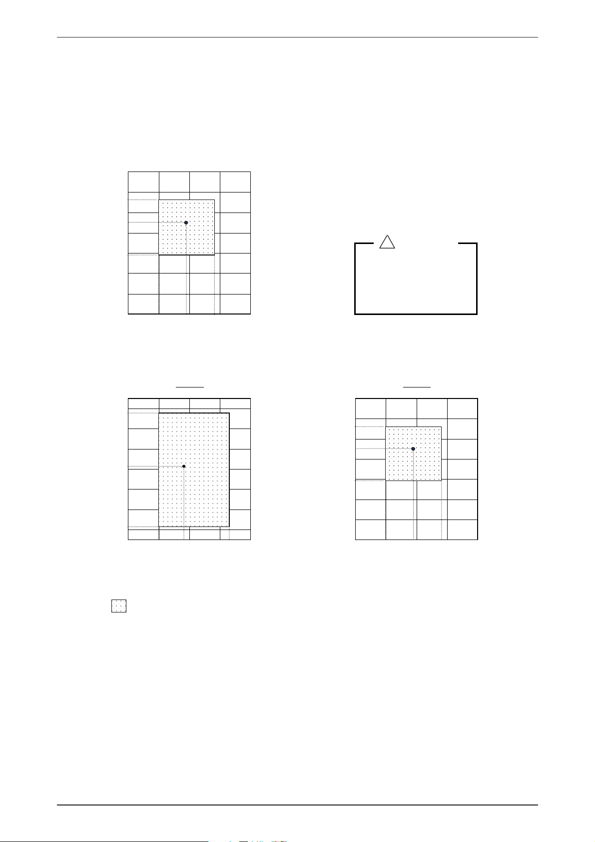
Clearance must be provided for the indoor unit from the wall and obstacles as shown in the fi gure.
•
maeB
m0.1.niM
m0.3.xaM
Obstacle
Floor
The installation place must be strong enough to support a load of 4 times the indoor unit weight to avoid
•
m5.0.niMm5.0.niMm5.0.niM
m3.0.xaM
amplifying noise and vibration.
The installation place (handling ceiling surface) must be level and the height in the ceiling is 350mm or
•
more.
Unit Installation
770.0 mm (Hanging rod)
)dorgnignaH(mm0.226
Piping Direction
The indoor unit must be away from heat and steam sources (avoid installing it near an entrance).
•
Measure and mark the position for the hanging rod. Drill the hole for the angle nut on the ceiling and fi x
•
the hanging rod.
The installation template is extended according to temperature and humidity. Check on dimensions in
•
using.
The dimensions of the installation template are same as those of the ceiling opening dimensions.
•
Before ceiling laminating work is completed, be sure to fi t the installation template to the indoor unit.
•
Note: Be sure to discuss the ceiling drilling work with the installers concerned.
20
Page 23

Application Information ACK-E-2009
Unit Hanging
Ceiling
Board
35.0mm
ACK-E
Confi rm the pitch of the hanging rod is 770mm x 622mm sharp.
•
Hold the unit and hand it on the hanging rod with the nut and washer.
•
Adjust the unit height to 35.0mm between the indoor unit bottom surface and the ceiling surface.
•
Confi rm with a level gauge that the unit is installed horizontally and tighten the nut and bol to prevent unit
•
falling and vibration.
Open the ceiling board along the outer edge of the paper installation template.
•
Drain Piping Work
Drain Test
Drain pipe must be downward gradient for smooth drainage.
•
Avoid the drain pipe from up and down slope to prevent
•
reversal fl ow.
During the drain piping connection, be careful not to exert extra
•
force on the drain connector at indoor unit.
The outside diameter of the drain connection at the fl exible
•
drain hose is 20mm.
Be sure to provide heat insulation (polyethylene foam with
•
thickness more than 8.0mm) on the drain piping to avoid the
condensed water dripping inside the room.
Connect the main drain pipe to the fl exible drain hose.
•
Feed water from fl exible drain hose and check the piping for
•
leakage.
When the test is completed, connect the fl exible drain hose to
•
the drain connector on the indoor unit.
Note: This indoor unit use drain pump for condensed water drainage. Install the unit horizontally to
prevent water leakage or condensation around the air outlet.
21
Page 24

ACK-E-2009 Application Information
Panel Installation
The front panel can only be fi tted in one direction, follow the piping direction. (Follow piping arrow sticker
•
on the front panel).
Be sure to remove the installation template before installing the front panel.
•
Open the air intake grille by pulling back the catchers and remove it together with fi lter from panel.
•
Install the front frame panel onto the indoor unit by using 4 screws and tighten it completely to prevent cool
•
air leakage.
Connect the LED wire and air swing wire to the indoor unit (Optional).
•
Note: Install the front frame panel fi rmly to prevent cool air leakage which will cause condensation
and water dripping.
22
Page 25

Application Information ACK-E-2009
Short Duct Specifi cation
The indoor unit is provided with air discharge and air intake “knock-out” hole for duct connection. However
•
the connection of the short duct for air discharge is possible on only one side.
The use of short duct for air discharge will improve air fl ow distribution if there is an obstruction (such as
•
alighting fi xture) or in a long, narrow room or an L-shaped room. It is also used for air-conditioning of two
rooms simultaneously.
Possible Direction For Air Discharge and Air Intake
Air DischargeAir Discharge
Air Intake
egrahcsiDriAegrahcsiDriA
Possible Opening Dimension for Duct Connection
Note: 1. Avoid to use the short duct on which the air discharge grille can be completely closed, to
prevent evaporator freezing.
2. In order to prevent condensation forming, be sure that there is suffi cient thermal insulation
and no leakage of cool air when installing the short duct.
3. Keep the introduction of fresh air intake within 20% of total air fl ow. Also provide a chamber
and use a booster fan.
23
Page 26

ACK-E-2009 Application Information
(2) Installation Of Outdoor Unit
As condensing temperature rises, evaporating temperature rises and cooling capacity drops. In order to achieve
maximum cooling capacity, the location selected for outdoor unit should fulfi ll the following requirements:
Install the condensing (outdoor) unit in a way such that hot air distributed by the outdoor condensing unit
•
cannot be drawn in again (as in the case of short circuit of hot discharge air). Allow suffi cient space for
maintenance around the unit.
Ensure that there is no obstruction of air fl ow into or out of the unit. Remove obstacles which block air
•
intake or discharge.
The location must be well ventilated, so that the unit can draw in and distribute plenty of air thus lowering
•
the condensing temperature.
A place capable of bearing the weight of the outdoor unit and isolating noise and vibration.
•
A place protected from direct sunlight. Otherwise use an awning for protection, if necessary.
•
The location must not be susceptible to dust or oil mist.
•
Installation Clearance
Outdoor units must be installed such that there is no short circuit of the hot discharge air or obstruction to
•
smooth air fl ow. Select the coolest possible place where intake air should not be hotter than the outside
temperature (max. 45˚C).
ALL MODELS A B C D
Minimum Distance 300 mm 1000 mm 300 mm 500 mm
CAUTION : If the condensing unit is operated in an atmosphere containing oils (including machine oils), salt (coastal area),
sulphide gas (near hot spring, oil refi nery plant), such substances may lead to failure of the unit.
24
Page 27

Application Information ACK-E-2009
(3) Refrigerant Piping
Maximum Piping Length and Maximum Number of Bends
When the pipe length becomes too long, both the capacity and reliability drop. As the number of bends
increases, system piping resistance to the refrigerant fl ow increases, thus lowering the cooling capacity,
and as the result the compressor may become defective. Always choose the shortest path and follow the
recommendation as tabulated below:
Model
Maximum Length, m 15 15 15 45 45
Maximum Elevation, m 8 8 8 25 25
Maximum No. of Bends 10 10 10 10 10
Indoor 20E/ER 25E/ER 28E/ER 40E/ER 50E/ER
Outdoor 20C/CR 25C/CR 28C/CR 35/40C/CR 50C/CR
Piping Sizes (Flare Connection Type)
Piping sizes are as follows:
R22
Model ALC 20C/CR ALC 25C/CR
Liquid (mm/in) 6.35 / 1/4 9.52 / 3/8
Suction (mm/in) 15.88 / 5/8 15.88 / 5/8
Model ALC 28C/CR ALC 35/ 40C/CR ALC 50C/CR
Liquid (mm/in) 9.52 / 3/8 9.52 / 3/8 9.52 / 3/8
Suction (mm/in) 15.88 / 5/8 19.05 / 3/4 19.05 / 3/4
R410A
Model A5LC 20C/CR A5LC 25C/CR
Liquid (mm/in) 6.35 / 1/4 6.35 / 1/4
Suction (mm/in) 12.70 / 1/2 15.88 / 5/8
Model A5LC 28C/CR A5LC 35C/CR A5LC 40C/CR A5LC 50C/CR
Liquid (mm/in) 9.52 / 3/8 9.52 / 3/8 9.52 / 3/8 9.52 / 3/8
Suction (mm/in) 15.88 / 5/8 15.88 / 5/8 15.88 / 5/8 15.88 / 5/8
25
Page 28

ACK-E-2009 Application Information
Piping Connection To The Units
Align the centre of the piping and tighten the fl are nut suffi ciently with fi ngers.
•
Finally tighten the fl are nut with torque wrench unit the wrench clicks.
•
When tightening the fl are nut with torque wrench, ensure the direction for tightening follows the arrow on
•
the wrench.
(4) Wiring
Electrical Connections
Wiring regulations on wire diameters differ from country to country. Please refer to your LOCAL ELECTRICAL
CODES for fi eld wiring rules. Be sure that installation is complied with such rules and regulations
.
General Precautions
Ensure that the rated voltage of the unit corresponds to the nameplate before carrying out proper wiring
•
according to the wiring diagram.
Provide a power outlet to be used exclusively for each unit. A power supply disconnects and a circuit
•
breaker for over current protection should be provided in the exclusive line.
All wiring must be GROUNDED to prevent possible hazards due to insulation failures.
•
All wiring must be fi rmly connected.
•
All wiring must not come in contact with the hot refrigerant piping, compressor or any moving parts of fan
•
motors.
Do not use joined and twisted wires for incoming power supply
•
26
Page 29
Application Information ACK-E-2009
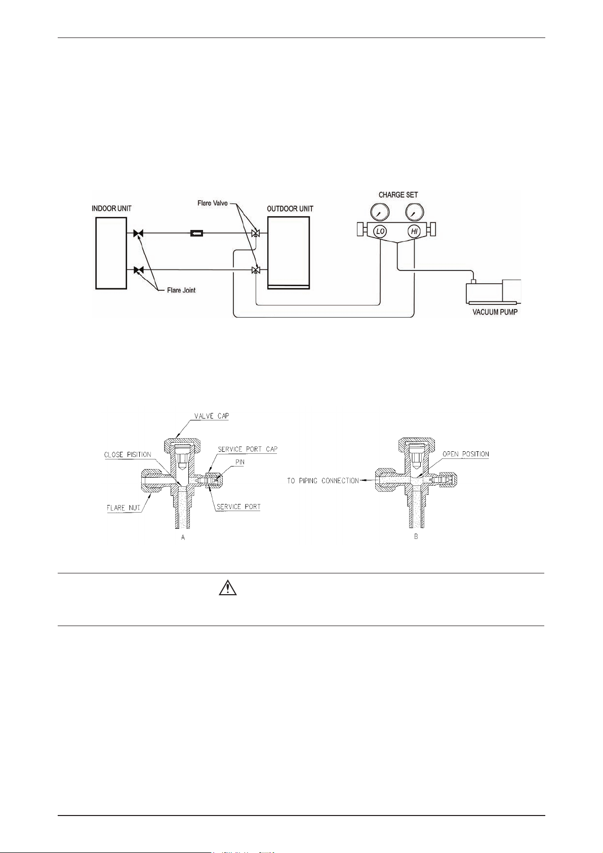
(5) Vacuuming and Charging
The pre-charged outdoor unit does not need any vacuuming or charging. However once it is connected, the
connecting pipe line and the indoor unit need to be vacuumed before releasing the R22/R407C/R410A from
the outdoor unit.
1. Open the service port core cap.
2. Connect pressure gauge to the service port.
3. Connect the line to vacuum pump. Open the charging manifold valve and turn the pump on. Vacuum to -0.1
MPa (-760mmHg) or lower. (Evacuation time varies by the pump but averagely in 1 hour).
Filter Dryer
(Mclecular-Sieve Type
Note : R407C- Fix filter dryer
R22 - Nil
R410A - Nil
4. After evacuation, unscrew the spindle (diagram B) for the gas to run to indoor unit.
Caution For R407C / R410A
Do not top-up when servicing leak, as this will reduce the unit performance. Vacuum the unit thoroughly
•
and then charge the unit with fresh R407C according to the amount recommended in the specifi cation.
27
Page 30

ACK-E-2009 Application Information
(6) Additional Charge
The refrigerant charge has already charged into the outdoor unit. For the piping length of 7.6m, additional
•
refrigerant charge after vacuuming is not necessary.
When the piping length is more than 7.6m, please use the table below (unit in gram).
•
R22
Model 10m 12m 15m 25m 35m 45m
20C/CR 38 / 53 70 / 96 118 / 162 - - -
25C/CR 94 / 53 172 / 98 289 / 164 - - -
28C/CR 94 / 133 172 / 244 291 / 411 - - -
30C/CR 133 / 133 244 / 243 410 / 409 964 / 961 1518 / 1514 2072 / 2067
35C/CR 130 / 136 238 / 248 400 / 418 940 / 983 1481 / 1547 2021 / 2112
40C/CR 134 / 136 245 / 248 412 / 418 968 / 983 1525 / 1547 2081 / 2112
50C/CR 130 / 134 238 / 245 400 / 412 942 / 968 1483 / 1525 2024 / 2081
R410A
Model 10m 15m 20m 25m 35m 45m
20C/CR 24 / 40 44 / 73 74 / 123 - - -
25C/CR 24 / 23 45 / 43 75 / 72 - - -
28C/CR 58 / 91 106 / 167 178 / 281 - - -
35C/CR 65 / 98 118 / 180 199 / 303 469 / 712 738 / 1122 1007 / 1531
40C/CR 61 / 97 112 / 178 189 / 299 445 / 703 700 / 1107 956 / 1511
50C/CR 50 / 87 92 / 159 155 / 267 363 / 628 572 / 989 781 / 1350
28
Page 31

Application Information ACK-E-2009
The additional refrigerant charge amount recommended is a guideline for longer piping application. The
actual charge required may be different from the guideline due to different application and variation in site
conditions.
Diagram shows typical charging method:
(Mclecular-Sieve Type)
Note : R407C - Fix filter dryer
R22 - Nil
R410A - Nil
Caution For R407C / R410A
Avoid prolong exposure of an opened compressor, or the internal part of refrigerant piping to moist air.
•
The POE oil in the compressor and piping can absorb moisture from air.
29
Page 32

ACK-E-2009 Application Information
Special Precautions When Dealing With Refrigerant R410A Unit
(1) What is New Refrigerant R410A?
R410A is a new HFC refrigerant which does not damage the ozone layer. The working pressure of this
new refrigerant is 1.6 times higher than conventional refrigerant (R22), thus proper installation / servicing
is essential.
(2) Components
Mixture weight composition R32(50%) and R125(50%)
(3) Characteristic
R410A liquid and vapor components have different compositions when the fl uid evaporates or
•
condenses. Hence, when leak occurs and only vapor leaks out, the composition of the refrigerant
mixture left in the system will change and subsequently affect the system performance. DO NOT add
new refrigerant to leaked system. It is recommended that the system should be evacuated thoroughly
before recharging with R410A.
When refrigerant R410A is used, the composition will differ depending on whether it is in gaseous or
•
liquid phase. Hence when charging R410A, ensure that only liquid is being withdrawn from the cylinder
or can. This is to make certain that only original composition of R410A is being charged into the system.
POE oil is used as lubricant for R410A compressor, which is different from the mineral oil used for R22
•
compressor. Extra precaution must be taken not to expose the R410A system too long to moist air.
(4) Check List Before Installation / Servicing
Tubing
•
Refrigerant R410A is more easily affected by dust of moisture compared with R22, make sure to
temporarily cover the ends of the tubing prior to installation.
Compressor oil
•
No additional charge of compressor oil is permitted.
Refrigerant
•
No other refrigerant other that R410A
Tools (size of service port is different from R22 system)
•
Tools specifi cally for R410A only (must not be used for R22 or other refrigerant)
i) Gauge manifold and charging hose
ii) Gas leak detector
iii) Refrigerant cylinder/charging cylinder
iv) Vacuum pump c/w adapter
v) Flare tools
vi) Refrigerant recovery machine
(5) Handling and Installation Guidelines
Like R22 system, the handling and installation of R410A system are closely similar. All precautionary
measures; such as ensuring no moisture, no dirt or chips in the system, clean brazing using nitrogen, and
thorough leak check and vacuuming are equally important requirements. However, due to its hydroscopic
POE oil, additional precautions must be taken to ensure optimum and trouble free system operation.
(a) During installation or servicing, avoid prolong exposure of the internal part of the refrigerant system to
moist air. Residual POE oil in the piping and components can absorb moisture from the air.
(b) Ensure that the compressor is not exposed to open air for more than the recommended time specifi ed
by its manufacturer (typically less than 10 minutes). Removed the seal plugs only when the compressor
is about to be brazed.
(c) The system should be thoroughly vacuumed to 1.0 Pa (700mmHg) or lower. This vacuuming level is
more stringent than R22 system so as to ensure no incompressible gas and moisture in the system.
30
Page 33

Application Information ACK-E-2009
(d) When charging R410A, ensure that only liquid is being withdrawn from the cylinder or can. This is
to ensure that only the original composition of R410A is being delivered into the system. The liquid
composition can be different from the vapor composition.
Invert cylinder
Dip-pipe
without dip-pipe
Liquid
withdrawal
(e) Normally, the R410A cylinder or can is being equipped with a dip pipe for liquid withdrawal. However,
if the dip pipe is not available, invert the cylinder or can so as to withdraw liquid from the valve at the
bottom.
31
Page 34

ACK-E-2009 Application Information
(7) Overall Checking
Ensure the following, in particular:
•
1. The unit is mounted solidly and rigid in position.
2. Piping and connections are leak proof after charging.
3. Proper wiring has been done.
Drainage check – pour some water into drain pan.
•
Test run
•
1. Conduct a test run after water drainage test and gas leakage test.
2. Watch out for the following:
(a) Is the electric plug fi rmly inserted into the socket?
(b) Is there any abnormal sound from the unit?
(c) Is there any abnormal vibration with regard to the unit itself or piping?
(d) Is there smooth drainage of water?
Check that:
•
1. Outdoor fan is running, with warm air blowing off the outdoor unit (cooling cycle).
2. Indoor blower is running and discharge cool air (cooling cycle).
3. Suction (low side) pressure is as per recommendations.
4. The remote controller has incorporated a 3 minutes delay in the circuit. Thus, it requires about 3 minutes
before the outdoor unit can start up.
(8) Standard Operating Condition
Cooling Only Unit
Temperature
Minimum Indoor Temperature 19.4 / 66.9 13.9 / 57.0
Maximum Indoor Temperature 26.7 / 80.1 19.4 / 66.9
Minimum Outdoor Temperature 19.4 / 66.9 13.9 / 57.0
Maximum Outdoor Temperature 46 / 114.8 24 / 75.2
Heat Pump Unit
Temperature
Minimum Indoor Temperature 10 / 50 -
Maximum Indoor Temperature 26.7 / 80.1 -
Minimum Outdoor Temperature -8 / 17.6 -9 / 15.8
Maximum Outdoor Temperature 24 / 75.2 18/ 64.4
Ts : Dry Bulb Temperature Th : Wet Bulb Temperature
Ts °C / °F Th °C / °F
Ts °C / °F Th °C / °F
32
Page 35

Sound Data ACK-E-2009
Sound Data
ACK-E/ER
Model
ACK 20E/ER
ACK 25E/ER
ACK 28E/ER
ACK 40E/ER
ACK 50E/ER
Speed
1/1 Octave A-Weighted Sound Pressure (dBA), ref 20μPa
125 Hz 250 Hz 500 Hz 1k Hz 2k Hz 4k Hz 8k Hz
Overall
A (dBA)
Noise
Criteria
High 37 38 35 26 17 8 6 34 30
Medium 34 34 33 21 11 5 6 31 28
Low 32 30 30 17 8 4 5 28 24
Super Low 32 28 29 16 7 4 5 27 23
High 39 40 37 29 22 13 6 37 32
Medium 37 38 35 26 18 9 5 34 30
Low 35 35 32 22 13 6 5 31 26
Super Low 34 34 31 20 10 5 6 30 25
High 45 43 42 35 29 22 11 41 37
Medium 40 41 39 30 24 15 7 38 34
Low 38 38 35 26 19 9 5 35 30
Super Low 35 35 33 23 14 5 4 32 28
High 48 45 44 38 30 28 15 44 39
Medium 49 42 41 34 25 21 8 41 36
Low 48 39 38 31 21 13 6 38 33
Super Low 45 35 36 26 15 5 5 35 31
High 50 48 46 42 33 32 20 47 41
Medium 52 45 43 38 29 27 13 44 38
Low 53 43 42 37 27 24 10 43 37
Super Low 51 41 39 32 23 16 6 39 34
Model Measuring location
ACK/A5CK 20E/ER
ACK/A5CK 25E/ER
ACK/A5CK 28E/ER
ACK/A5CK 40E/ER
ACK/A5CK 50E/ER
1.4m
Microphone
Standard : JIS C 9612
1.5m
Microphone
Standard : JIS B 8615
33
Page 36

ACK-E-2009 Sound Data
ACK 20E/ER NC Curve
80
70
60
50
40
Sound pressure level (dB, ref 20μPa)
30
Super High Fan
High Fan
20
Medium Fan
Low Fan
10
63 125 250 500 1000 2000 4000 8000
Octave-band frequency (Hz)
NC70
NC65
NC60
NC55
NC50
NC45
NC40
NC35
NC30
NC25
NC20
ACK 25E/ER NC Curve
80
70
60
50
40
30
Sound pressure level (dB, ref 20μPa)
20
10
63 125 250 500 1000 2000 4000 8000
Octave-band frequency (Hz)
Super High Fan
High Fan
Medium Fan
Low Fan
NC70
NC65
NC60
NC55
NC50
NC45
NC40
NC35
NC30
NC25
NC20
34
Page 37

Sound Data ACK-E-2009
ACK 28E/ER NC Curve
80
70
60
50
40
Super High Fan
30
Sound pressure level (dB, ref 20μPa)
High Fan
Medium Fan
20
Low Fan
10
63 125 250 500 1000 2000 4000 8000
Octave-band frequency (Hz)
NC70
NC65
NC60
NC55
NC50
NC45
NC40
NC35
NC30
NC25
NC20
ACK 40E/ER NC Curve
80
70
60
50
40
30
Sound pressure level (dB, ref 20μPa)
20
10
63 125 250 500 1000 2000 4000 8000
Octave-band frequency (Hz)
Super High Fan
High Fan
Medium Fan
Low Fan
NC70
NC65
NC60
NC55
NC50
NC45
NC40
NC35
NC30
NC25
NC20
35
Page 38

ACK-E-2009 Sound Data
ACK 50E/ER NC Curve
80
70
60
50
40
Super High Fan
Sound pressure level (dB, ref 20μPa)
30
High Fan
Medium Fan
20
10
63 125 250 500 1000 2000 4000 8000
Low Fan
Octave-band frequency (Hz)
NC70
NC65
NC60
NC55
NC50
NC45
NC40
NC35
NC30
NC25
NC20
36
Page 39

Engineering & Physical Data ACK-E-2009
Engineering & Physical Data
General Data - Cooling Only (R22)
MODEL
NOMINAL CAPACITY
NOMINAL TOTAL INPUT POWER W 1960 2540
NOMINAL RUNNING CURRENT A 8.8 11.5
POWER SOURCE V/Ph/Hz 220 - 240 / 1 / 50 220 - 240 / 1 / 50
EER W/W 2.91 2.89
REFRIGERANT TYPE R22 R22
REFRIGERANT CONTROL (EXPANSION DEVICE) OUTDOOR CAP. TUBE OUTDOOR CAP. TUBE
AIR DISCHARGE
CONTROL
AIR FLOW
EXTERNAL STATIC PRESSURE (H/M/L) Pa / in.wg. 00
SOUND PRESSURE LEVEL (H/M/L) dBA 34 / 31 / 28 37 / 34 / 31
UNIT DIMENSION
INDOOR UNIT
( ) - WITH PANEL
PACKING DIMENSION
( ) - PANEL
UNIT WEIGHT (UNIT + PANEL) kg/lb 29+6 / 63.9+13.2 29+6 / 63.9+13.2
CONDENSATE DRAIN SIZE
AIR FLOW l/s / CFM 614 / 1300 755 / 1600
SOUND PRESSURE LEVEL dBA 51 52
UNIT DIMENSION
PACKING DIMENSION
OUTDOOR UNIT
UNIT WEIGHT kg/lb 59 / 130 62 / 137
PIPE CONNECTION
REFRIGERANT CHARGE kg/lb 1 / 2.20 1.25 / 2.76
OPERATION WIRELESS OR WIRED MICRO-
HIGH l/s / CFM 280 / 600 320 / 680
MEDIUM l/s / CFM 250 / 530 280 / 600
LOW l/s / CFM 200 / 430 250 / 530
INDOOR UNIT ACK 20E ACK 25E
OUTDOOR UNIT ALC 20C ALC 25C
Btu/h 19500 25000
W 5715 7327
4 WAY AUTOMATIC LOUVER
(UP & DOWN)
COMPUTER REMOTE CONTROL
HEIGHT mm/in 265 (340) /10.43 (13.39) 265 (340) / 10.43 (13.39)
WIDTH mm/in 820 (990) / 32.3 (38.98) 820 (990) / 32.3 (38.98)
DEPTH mm/in 820 (990) / 32.3 (38.98) 820 (990) / 32.3 (38.98)
HEIGHT mm/in 300 (110) / 11.8 (4.33) 300 (110) / 11.8 (4.33)
WIDTH mm/in 916 (1030) / 36.1 (40.6) 916 (1030) / 36.1 (40.6)
DEPTH mm/in 916 (1030) / 36.1 (40.6) 916 (1030) / 36.1 (40.6)
mm/in 19.1 / 0.75 19.1 / 0.75
HEIGHT mm/in 654 / 25.7 756 / 29.8
WIDTH mm/in 855 / 33.7 855 / 33.7
DEPTH mm/in 328 / 12.9 328 / 12.9
HEIGHT
WIDTH mm/in 990 / 39.0 990 / 39.0
DEPTH mm/in 415 / 16.3 415 / 16.3
TYPE FLARE VALVE FLARE VALVE
SIZE
LIQUID mm/in 6.4 / 1/4 9.5 / 3/8
GAS mm/in 15.9 / 5/8 15.9 / 5/8
mm/in 710 / 28.0 810 / 31.9
4 WAY AUTOMATIC LOUVER
(UP & DOWN)
WIRELESS OR WIRED MICRO-
COMPUTER REMOTE CONTROL
1) ALL SPECIFICATIONS ARE SUBJECTED TO CHANGE BY THE MANUFACTURER WITHOUT PRIOR NOTICE.
2) ALL UNITS ARE BEING TESTED AND COMPLY TO ISO 5151.
3) NOMINAL COOLING AND HEATING CAPACITY ARE BASED ON THE CONDITIONS BELOW :
COOLING - 27°C DB / 19°C WB INDOOR AND 35°C DB / 24°C WB OUTDOOR
4) SOUND PRESSURE LEVEL ARE ACCORDING TO JIS C 9612 STANDARD. POSITION OF THE MEASUREMENT POINT IS 1.4m BELOW FASCIA.
37
Page 40

ACK-E-2009 Engineering & Physical Data
General Data - Cooling Only (R22)
MODEL
NOMINAL CAPACITY
NOMINAL TOTAL INPUT POWER
NOMINAL RUNNING CURRENT A 12.3
POWER SOURCE V/Ph/Hz 220 - 240 / 1 / 50
EER W/W 2.91
REFRIGERANT TYPE R22
REFRIGERANT CONTROL (EXPANSION DEVICE) INDOOR CAP. TUBE
AIR DISCHARGE
CONTROL
OPERATION
HIGH l/s / CFM 410 / 860
AIR FLOW
EXTERNAL STATIC PRESSURE (H/M/L) Pa / in.wg. 0
SOUND PRESSURE LEVEL (H/M/L) dBA 41 / 38 / 35
UNIT DIMENSION
INDOOR UNIT
( ) - WITH PANEL
PACKING DIMENSION
( ) - PANEL
UNIT WEIGHT (UNIT + PANEL) kg/lb 29+6 / 63.9+13.2
CONDENSATE DRAIN SIZE mm/in 19.1 / 0.75
AIR FLOW l/s / CFM 741 / 1570
SOUND PRESSURE LEVEL dBA 54
UNIT DIMENSION
PACKING DIMENSION
OUTDOOR UNIT
UNIT WEIGHT kg/lb 68 / 150
PIPE CONNECTION
REFRIGERANT CHARGE kg/lb 2.20 / 4.85
1) ALL SPECIFICATIONS ARE SUBJECTED TO CHANGE BY THE MANUFACTURER WITHOUT PRIOR NOTICE.
2) ALL UNITS ARE BEING TESTED AND COMPLY TO ISO 5151.
3) NOMINAL COOLING AND HEATING CAPACITY ARE BASED ON THE CONDITIONS BELOW :
COOLING - 27°C DB / 19°C WB INDOOR AND 35°C DB / 24°C WB OUTDOOR
4) SOUND PRESSURE LEVEL ARE ACCORDING TO JIS B 8615 STANDARD. POSITION OF THE MEASUREMENT POINT IS 1.5m BELOW FASCIA.
MEDIUM l/s / CFM 340 / 725
LOW l/s / CFM 290 / 620
INDOOR UNIT ACK 28E
OUTDOOR UNIT ALC 28C
Btu/h 27000
W 7913
W 2720
4 WAY AUTOMATIC LOUVER
(UP & DOWN)
WIRELESS OR WIRED MICRO-
COMPUTER REMOTE CONTROL
HEIGHT mm/in 265 (340) / 10.43 (13.39)
WIDTH mm/in 820 (990) / 32.3 (38.98)
DEPTH mm/in 820 (990) / 32.3 (38.98)
HEIGHT mm/in 300 (110) / 11.8 (4.33)
WIDTH mm/in 916 (1030) / 36.1 (40.6)
DEPTH mm/in 916 (1030) / 36.1 (40.6)
HEIGHT mm/in 756 / 29.8
WIDTH mm/in 855 / 33.7
DEPTH mm/in 328 / 12.9
HEIGHT
WIDTH mm/in 990 / 39.0
DEPTH mm/in 415 / 16.3
TYPE FLARE VALVE
SIZE
LIQUID mm/in 9.5 / 3/8
GAS mm/in 15.9 / 5/8
mm/in 810 / 31.9
38
Page 41

Engineering & Physical Data ACK-E-2009
General Data - Cooling Only (R22)
MODEL
NOMINAL CAPACITY - 1Ø <3Ø>
NOMINAL TOTAL INPUT POWER - 1Ø <3Ø>
NOMINAL RUNNING CURRENT - 1Ø <3Ø> A 14.4 16.7 <5.8>
POWER SOURCE - 1Ø <3Ø>
EER - 1Ø <3Ø> W/W 3.41 3.31 / <3.59>
REFRIGERANT TYPE R22 R22
REFRIGERANT CONTROL (EXPANSION DEVICE) INDOOR CAP. TUBE INDOOR CAP. TUBE
AIR DISCHARGE
CONTROL
OPERATION
HIGH l/s / CFM 490 / 1030 490 / 1030
AIR FLOW
EXTERNAL STATIC PRESSURE (H/M/L) Pa / in.wg. 00
SOUND PRESSURE LEVEL (H/M/L) dBA 44 / 41 / 38 44 / 41 / 38
UNIT DIMENSION
INDOOR UNIT
( ) - WITH PANEL
PACKING DIMENSION
( ) - PANEL
UNIT WEIGHT (UNIT + PANEL) kg/lb 42+6 / 92.6+13.2 42+6 / 92.6+13.2
CONDENSATE DRAIN SIZE mm/in 19.1 / 0.75 19.1 / 0.75
AIR FLOW l/s / CFM 1605 / 3400 1605 / 3400
SOUND PRESSURE LEVEL dBA 58 58
UNIT DIMENSION
PACKING DIMENSION
OUTDOOR UNIT
UNIT WEIGHT kg/lb 95 / 209 100 / 221
PIPE CONNECTION
REFRIGERANT CHARGE kg/lb 2.7 / 5.95 2.95 / 6.50
1) ALL SPECIFICATIONS ARE SUBJECTED TO CHANGE BY THE MANUFACTURER WITHOUT PRIOR NOTICE.
2) ALL UNITS ARE BEING TESTED AND COMPLY TO ISO 5151.
3) NOMINAL COOLING AND HEATING CAPACITY ARE BASED ON THE CONDITIONS BELOW :
COOLING - 27°C DB / 19°C WB INDOOR AND 35°C DB / 24°C WB OUTDOOR
4) SOUND PRESSURE LEVEL ARE ACCORDING TO JIS B 8615 STANDARD. POSITION OF THE MEASUREMENT POINT IS 1.5m BELOW FASCIA.
MEDIUM l/s / CFM 410 / 860 410 / 860
LOW l/s / CFM 350 / 740 350 / 740
INDOOR UNIT ACK 40E ACK 40E
OUTDOOR UNIT ALC 35C ALC 40C
Btu/h 35000 39000 <40000>
W 10258 11430 <11723>
W 3010 3450 <3260>
V/Ph/Hz 220 - 240 / 1 / 50
4 WAY AUTOMATIC LOUVER
(UP & DOWN)
WIRELESS OR WIRED MICRO-
COMPUTER REMOTE CONTROL
HEIGHT mm/in 300 (375) / 11.81 (14.76) 300 (375) / 11.81 (14.76)
WIDTH mm/in 820 (990) / 32.3 (38.98) 820 (990) / 32.3 (38.98)
DEPTH mm/in 820 (990) / 32.3 (38.98) 820 (990) / 32.3 (38.98)
HEIGHT mm/in 335 (110) / 13.19 (4.3) 335 (110) / 13.19 (4.3)
WIDTH mm/in 916 (1030) / 36.1 (40.6) 916 (1030) / 36.1 (40.6)
DEPTH mm/in 916 (1030) / 36.1 (40.6) 916 (1030) / 36.1 (40.6)
HEIGHT mm/in 850 / 33.5 850 / 33.5
WIDTH mm/in 1030 / 40.6 1030 / 40.6
DEPTH mm/in 400 / 15.8 400 / 15.8
HEIGHT
WIDTH mm/in 1200 / 47.2 1200 / 47.2
DEPTH mm/in 560 / 22.1 560 / 22.1
TYPE FLARE VALVE FLARE VALVE
SIZE
LIQUID mm/in 9.5 / 3/8 9.5 / 3/8
GAS mm/in 19.1 / 3/4 19.1 / 3/4
mm/in 1000 / 39.4 1000 / 39.4
220 - 240 / 1 / 50
<380 - 415 / 3 / 50>
4 WAY AUTOMATIC LOUVER
(UP & DOWN)
WIRELESS OR WIRED MICRO-
COMPUTER REMOTE CONTROL
39
Page 42

ACK-E-2009 Engineering & Physical Data
General Data - Cooling Only (R22)
MODEL
NOMINAL CAPACITY
NOMINAL TOTAL INPUT POWER
NOMINAL RUNNING CURRENT A 7.9
POWER SOURCE V/Ph/Hz 380 - 415 / 3 / 50
EER W/W 3.03
REFRIGERANT TYPE R22
REFRIGERANT CONTROL (EXPANSION DEVICE) INDOOR CAP. TUBE
AIR DISCHARGE
CONTROL
OPERATION
HIGH l/s / CFM 570 / 1200
AIR FLOW
EXTERNAL STATIC PRESSURE (H/M/L) Pa / in.wg. 0
SOUND PRESSURE LEVEL (H/M/L) dBA 47 / 44 / 43
UNIT DIMENSION
INDOOR UNIT
( ) - WITH PANEL
PACKING DIMENSION
( ) - PANEL
UNIT WEIGHT (UNIT + PANEL) kg/lb 42+6 / 92.6+13.2
CONDENSATE DRAIN SIZE mm/in 19.1 / 0.75
AIR FLOW l/s / CFM 1605 / 3400
SOUND PRESSURE LEVEL dBA 58
UNIT DIMENSION
PACKING DIMENSION
OUTDOOR UNIT
UNIT WEIGHT kg/lb 105 / 232
PIPE CONNECTION
REFRIGERANT CHARGE kg/lb 2.55 / 5.62
1) ALL SPECIFICATIONS ARE SUBJECTED TO CHANGE BY THE MANUFACTURER WITHOUT PRIOR NOTICE.
2) ALL UNITS ARE BEING TESTED AND COMPLY TO ISO 5151.
3) NOMINAL COOLING AND HEATING CAPACITY ARE BASED ON THE CONDITIONS BELOW :
COOLING - 27°C DB / 19°C WB INDOOR AND 35°C DB / 24°C WB OUTDOOR
4) SOUND PRESSURE LEVEL ARE ACCORDING TO JIS B 8615 STANDARD. POSITION OF THE MEASUREMENT POINT IS 1.5m BELOW FASCIA.
MEDIUM l/s / CFM 490 / 1030
LOW l/s / CFM 440 / 930
INDOOR UNIT ACK 50E
OUTDOOR UNIT ALC 50C
Btu/h 47500
W 13921
W 4600
4 WAY AUTOMATIC LOUVER
(UP & DOWN)
WIRELESS OR WIRED MICRO-
COMPUTER REMOTE CONTROL
HEIGHT mm/in 300 (375) / 11.81 (14.76)
WIDTH mm/in 820 (990) / 32.3 (38.98)
DEPTH mm/in 820 (990) / 32.3 (38.98)
HEIGHT mm/in 335 (110) / 13.19 (4.3)
WIDTH mm/in 916 (1030) / 36.1 (40.6)
DEPTH mm/in 916 (1030) / 36.1 (40.6)
HEIGHT mm/in 850 / 33.5
WIDTH mm/in 1030 / 40.6
DEPTH mm/in 400 / 15.8
HEIGHT
WIDTH mm/in 1200 / 47.2
DEPTH mm/in 560 / 22.1
TYPE FLARE VALVE
SIZE
LIQUID mm/in 9.5 / 3/8
GAS mm/in 19.1 / 3/4
mm/in 1000 / 39.4
40
Page 43

Engineering & Physical Data ACK-E-2009
General Data - Heat Pump (R22)
MODEL
NOMINAL COOLING CAPACITY
NOMINAL HEATING CAPACITY
NOMINAL TOTAL INPUT POWER (COOLING) W 1960 2540
NOMINAL TOTAL INPUT POWER (HEATING) W 1690 2310
NOMINAL RUNNING CURRENT (COOLING) A 8.8 11.5
NOMINAL RUNNING CURRENT (HEATING) A 7.6 10.4
POWER SOURCE V/Ph/Hz 220 - 240 / 1 / 50 220 - 240 / 1 / 50
EER W/W 2.91 2.89
COP W/W 3.38 3.17
REFRIGERANT TYPE R22 R22
REFRIGERANT CONTROL (EXPANSION DEVICE) OUTDOOR CAP. TUBE OUTDOOR CAP. TUBE
AIR DISCHARGE
CONTROL
OPERATION
HIGH l/s / CFM 280 / 600 320 / 680
AIR FLOW
EXTERNAL STATIC PRESSURE (H/M/L) mmAq 00
SOUND PRESSURE LEVEL (H/M/L) dBA 34 / 31 / 28 37 / 34 / 31
UNIT DIMENSION
INDOOR UNIT
( ) - WITH PANEL
PACKING DIMENSION
( ) - PANEL
UNIT WEIGHT kg/lb 29+6 / 63.9+13.2 29+6 / 63.9+13.2
CONDENSATE DRAIN SIZE mm/in 19.1 / 0.75 19.1 / 0.75
AIR FLOW l/s / CFM 614 / 1300 755 / 1600
SOUND PRESSURE LEVEL dBA 51 52
UNIT DIMENSION
PACKING DIMENSION
OUTDOOR UNIT
UNIT WEIGHT kg/lb 59 / 130 62 / 137
PIPE CONNECTION
REFRIGERANT CHARGE kg/lb 1.8 / 3.97 1.88 / 4.14
MEDIUM l/s / CFM 250 / 530 280 / 600
LOW l/s / CFM 200 / 430 250 / 530
INDOOR UNIT ACK 20ER ACK 25ER
OUTDOOR UNIT ALC 20CR ALC 25CR
Btu/h 19500 25000
W 5715 7327
Btu/h 19500 25000
W 5715 7327
4 WAY AUTOMATIC LOUVER
(UP & DOWN)
WIRELESS OR WIRED MICRO-
COMPUTER REMOTE CONTROL
HEIGHT mm/in 265 (340) /10.43 (13.39) 265 (340) / 10.43 (13.39)
WIDTH mm/in 820 (990) / 32.3 (38.98) 820 (990) / 32.3 (38.98)
DEPTH mm/in 820 (990) / 32.3 (38.98) 820 (990) / 32.3 (38.98)
HEIGHT mm/in 300 (110) / 11.8 (4.33) 300 (110) / 11.8 (4.33)
WIDTH mm/in 916 (1030) / 36.1 (40.6) 916 (1030) / 36.1 (40.6)
DEPTH mm/in 916 (1030) / 36.1 (40.6) 916 (1030) / 36.1 (40.6)
HEIGHT mm/in 654 / 25.7 756 / 29.8
WIDTH mm/in 855 / 33.7 855 / 33.7
DEPTH mm/in 328 / 12.9 328 / 12.9
HEIGHT
WIDTH mm/in 990 / 39.0 990 / 39.0
DEPTH mm/in 415 / 16.3 415 / 16.3
TYPE FLARE VALVE FLARE VALVE
SIZE
LIQUID mm/in 6.4 / 1/4 9.5 / 3/8
GAS mm/in 15.9 / 5/8 15.9 / 5/8
mm/in 710 / 28.0 810 / 31.9
4 WAY AUTOMATIC LOUVER
(UP & DOWN)
WIRELESS OR WIRED MICRO-
COMPUTER REMOTE CONTROL
1) ALL SPECIFICATIONS ARE SUBJECTED TO CHANGE BY THE MANUFACTURER WITHOUT PRIOR NOTICE.
2) ALL UNITS ARE BEING TESTED AND COMPLY TO ISO 5151.
3) NOMINAL COOLING AND HEATING CAPACITY ARE BASED ON THE CONDITIONS BELOW :
a) COOLING - 27°C DB / 19°C WB INDOOR AND 35°C DB / 24°C WB OUTDOOR
b) HEATING - 20°C DB INDOOR AND 7°C DB / 6°C WB OUTDOOR
4) SOUND PRESSURE LEVEL ARE ACCORDING TO JIS C 9612 STANDARD. POSITION OF THE MEASUREMENT POINT IS 1.4m BELOW FASCIA.
41
Page 44

ACK-E-2009 Engineering & Physical Data
General Data - Heat Pump (R22)
MODEL
NOMINAL COOLING CAPACITY
NOMINAL HEATING CAPACITY
NOMINAL TOTAL INPUT POWER (COOLING) W 2720
NOMINAL TOTAL INPUT POWER (HEATING) W 2350
NOMINAL RUNNING CURRENT (COOLING) A 12.3
NOMINAL RUNNING CURRENT (HEATING) A 10.9
POWER SOURCE V/Ph/Hz 220 - 240 / 1 / 50
EER W/W 2.91
COP W/W 3.50
REFRIGERANT TYPE R22
REFRIGERANT CONTROL (EXPANSION DEVICE) OUTDOOR CAP. TUBE
AIR DISCHARGE
CONTROL
OPERATION
HIGH l/s / CFM 410 / 860
AIR FLOW
EXTERNAL STATIC PRESSURE (H/M/L) mmAq 0
SOUND PRESSURE LEVEL (H/M/L) dBA 41 / 38 / 35
UNIT DIMENSION
INDOOR UNIT
( ) - WITH PANEL
PACKING DIMENSION
( ) - PANEL
UNIT WEIGHT kg/lb 29+6 / 63.9+13.2
CONDENSATE DRAIN SIZE mm/in 19.1 / 0.75
AIR FLOW l/s / CFM 741 / 1570
SOUND PRESSURE LEVEL dBA 54
UNIT DIMENSION
PACKING DIMENSION
OUTDOOR UNIT
UNIT WEIGHT kg/lb 68 / 150
PIPE CONNECTION
REFRIGERANT CHARGE kg/lb 1.85 / 4.08
1) ALL SPECIFICATIONS ARE SUBJECTED TO CHANGE BY THE MANUFACTURER WITHOUT PRIOR NOTICE.
2) ALL UNITS ARE BEING TESTED AND COMPLY TO ISO 5151.
3) NOMINAL COOLING AND HEATING CAPACITY ARE BASED ON THE CONDITIONS BELOW :
a) COOLING - 27°C DB / 19°C WB INDOOR AND 35°C DB / 24°C WB OUTDOOR
b) HEATING - 20°C DB INDOOR AND 7°C DB / 6°C WB OUTDOOR
4) SOUND PRESSURE LEVEL ARE ACCORDING TO JIS B 8615 STANDARD. POSITION OF THE MEASUREMENT POINT IS 1.5m BELOW FASCIA.
MEDIUM l/s / CFM 340 / 725
LOW l/s / CFM 290 / 620
INDOOR UNIT ACK 28ER
OUTDOOR UNIT ALC 28CR
Btu/h 27000
W 7913
Btu/h 28000
W 8206
4 WAY AUTOMATIC LOUVER
(UP & DOWN)
WIRELESS OR WIRED MICRO-
COMPUTER REMOTE CONTROL
HEIGHT mm/in 265 (340) / 10.43 (13.39)
WIDTH mm/in 820 (990) / 32.3 (38.98)
DEPTH mm/in 820 (990) / 32.3 (38.98)
HEIGHT mm/in 300 (110) / 11.8 (4.33)
WIDTH mm/in 916 (1030) / 36.1 (40.6)
DEPTH mm/in 916 (1030) / 36.1 (40.6)
HEIGHT mm/in 756 / 29.8
WIDTH mm/in 855 / 33.7
DEPTH mm/in 328 / 12.9
HEIGHT
WIDTH mm/in 990 / 39.0
DEPTH mm/in 415 / 16.3
TYPE FLARE VALVE
SIZE
LIQUID mm/in 9.5 / 3/8
GAS mm/in 15.9 / 5/8
mm/in 810 / 31.9
42
Page 45

Engineering & Physical Data ACK-E-2009
General Data - Heat Pump (R22)
MODEL
NOMINAL COOLING CAPACITY - 1Ø <3Ø>
NOMINAL HEATING CAPACITY - 1Ø <3Ø>
NOMINAL TOTAL INPUT POWER (COOLING) - 1Ø <3Ø> W 3010 3450 / <3260>
NOMINAL TOTAL INPUT POWER (HEATING) - 1Ø <3Ø> W 2750 3250 / <3200>
NOMINAL RUNNING CURRENT (COOLING) - 1Ø <3Ø> A 14.4 16.7 / <5.8>
NOMINAL RUNNING CURRENT (HEATING) - 1Ø <3Ø> A 13.4 15.9 / <6.0>
POWER SOURCE - 1Ø <3Ø>
EER - 1Ø / <3Ø> W/W 3.41 3.31 / <3.59>
COP - 1Ø / <3Ø> W/W 3.73 3.70 / <3.84>
REFRIGERANT TYPE R22 R22
REFRIGERANT CONTROL (EXPANSION DEVICE) OUTDOOR CAP. TUBE + TXV OUTDOOR CAP. TUBE + TXV
AIR DISCHARGE
CONTROL
OPERATION
HIGH l/s / CFM 490 / 1030 490 / 1030
AIR FLOW
EXTERNAL STATIC PRESSURE (H/M/L) mmAq 00
SOUND PRESSURE LEVEL (H/M/L) dBA 44 / 41 / 38 44 / 41 / 38
UNIT DIMENSION
INDOOR UNIT
( ) - WITH PANEL
PACKING DIMENSION
( ) - PANEL
UNIT WEIGHT kg/lb 42+6 / 92.6+13.2 42+6 / 92.6+13.2
CONDENSATE DRAIN SIZE mm/in 19.1 / 0.75 19.1 / 0.75
AIR FLOW l/s / CFM 1605 / 3400 1605 / 3400
SOUND PRESSURE LEVEL dBA 58 58
UNIT DIMENSION
PACKING DIMENSION
OUTDOOR UNIT
UNIT WEIGHT kg/lb 95 / 209 100 / 221
PIPE CONNECTION
REFRIGERANT CHARGE kg/lb 2.7 / 5.95 2.95 / 6.50
1) ALL SPECIFICATIONS ARE SUBJECTED TO CHANGE BY THE MANUFACTURER WITHOUT PRIOR NOTICE.
2) ALL UNITS ARE BEING TESTED AND COMPLY TO ISO 5151.
3) NOMINAL COOLING AND HEATING CAPACITY ARE BASED ON THE CONDITIONS BELOW :
a) COOLING - 27°C DB / 19°C WB INDOOR AND 35°C DB / 24°C WB OUTDOOR
b) HEATING - 20°C DB INDOOR AND 7°C DB / 6°C WB OUTDOOR
4) SOUND PRESSURE LEVEL ARE ACCORDING TO JIS B 8615 STANDARD. POSITION OF THE MEASUREMENT POINT IS 1.5m BELOW FASCIA.
MEDIUM l/s / CFM 410 / 860 410 / 860
LOW l/s / CFM 350 / 740 350 / 740
INDOOR UNIT ACK 40ER ACK 40ER
OUTDOOR UNIT ALC 35CR ALC 40CR
Btu/h 35000 39000 / <40000>
W 10258 11430 / <11723>
Btu/h 35000 41000 / <42000>
W 10258 12010 / <12309>
V/Ph/Hz
HEIGHT mm/in 300 (375) / 11.81 (14.76) 300 (375) / 11.81 (14.76)
WIDTH mm/in 820 (990) / 32.3 (38.98) 820 (990) / 32.3 (38.98)
DEPTH mm/in 820 (990) / 32.3 (38.98) 820 (990) / 32.3 (38.98)
HEIGHT mm/in 335 (110) / 13.19 (4.3) 335 (110) / 13.19 (4.3)
WIDTH mm/in 916 (1030) / 36.1 (40.6) 916 (1030) / 36.1 (40.6)
DEPTH mm/in 916 (1030) / 36.1 (40.6) 916 (1030) / 36.1 (40.6)
HEIGHT mm/in 850 / 33.5 850 / 33.5
WIDTH mm/in 1030 / 40.6 1030 / 40.6
DEPTH mm/in 400 / 15.8 400 / 15.8
HEIGHT
WIDTH mm/in 1200 / 47.2 1200 / 47.2
DEPTH mm/in 560 / 22.1 560 / 22.1
TYPE FLARE VALVE FLARE VALVE
SIZE
LIQUID mm/in 9.5 / 3/8 9.5 / 3/8
GAS mm/in 19.1 / 3/4 19.1 / 3/4
mm/in 1000 / 39.4 1000 / 39.4
220 - 240 / 1 / 50
<380 - 415 / 3 / 50>
4 WAY AUTOMATIC LOUVER
(UP & DOWN)
WIRELESS OR WIRED MICRO-
COMPUTER REMOTE CONTROL
220 - 240 / 1 / 50
<380 - 415 / 3 / 50>
4 WAY AUTOMATIC LOUVER
(UP & DOWN)
WIRELESS OR WIRED MICRO-
COMPUTER REMOTE CONTROL
43
Page 46

ACK-E-2009 Engineering & Physical Data
General Data - Heat Pump (R22)
MODEL
NOMINAL COOLING CAPACITY
NOMINAL HEATING CAPACITY
NOMINAL TOTAL INPUT POWER (COOLING) W 4600
NOMINAL TOTAL INPUT POWER (HEATING) W 4070
NOMINAL RUNNING CURRENT (COOLING) A 7.9
NOMINAL RUNNING CURRENT (HEATING) A 7.1
POWER SOURCE V/Ph/Hz 380 - 415 / 3 / 50
EER W/W 3.03
COP W/W 3.46
REFRIGERANT TYPE R22
REFRIGERANT CONTROL (EXPANSION DEVICE) OUTDOOR CAP. TUBE + TXV
AIR DISCHARGE
CONTROL
OPERATION
HIGH l/s / CFM 570 / 1200
AIR FLOW
EXTERNAL STATIC PRESSURE (H/M/L) mmAq 0
SOUND PRESSURE LEVEL (H/M/L) dBA 47 / 44 / 43
UNIT DIMENSION
INDOOR UNIT
( ) - WITH PANEL
PACKING DIMENSION
( ) - PANEL
UNIT WEIGHT kg/lb 42+6 / 92.6+13.2
CONDENSATE DRAIN SIZE mm/in 19.1 / 0.75
AIR FLOW l/s / CFM 1605 / 3400
SOUND PRESSURE LEVEL dBA 58
UNIT DIMENSION
PACKING DIMENSION
OUTDOOR UNIT
UNIT WEIGHT kg/lb 105 / 232
PIPE CONNECTION
REFRIGERANT CHARGE kg/lb 2.9 / 6.39
1) ALL SPECIFICATIONS ARE SUBJECTED TO CHANGE BY THE MANUFACTURER WITHOUT PRIOR NOTICE.
2) ALL UNITS ARE BEING TESTED AND COMPLY TO ISO 5151.
3) NOMINAL COOLING AND HEATING CAPACITY ARE BASED ON THE CONDITIONS BELOW :
a) COOLING - 27°C DB / 19°C WB INDOOR AND 35°C DB / 24°C WB OUTDOOR
b) HEATING - 20°C DB INDOOR AND 7°C DB / 6°C WB OUTDOOR
4) SOUND PRESSURE LEVEL ARE ACCORDING TO JIS B 8615 STANDARD. POSITION OF THE MEASUREMENT POINT IS 1.5m BELOW FASCIA.
MEDIUM l/s / CFM 490 / 1030
LOW l/s / CFM 440 / 930
INDOOR UNIT ACK 50ER
OUTDOOR UNIT ALC 50CR
Btu/h 47500
W 13921
Btu/h 48000
W 14068
4 WAY AUTOMATIC LOUVER
(UP & DOWN)
WIRELESS OR WIRED MICRO-
COMPUTER REMOTE CONTROL
HEIGHT mm/in 300 (375) / 11.81 (14.76)
WIDTH mm/in 820 (990) / 32.3 (38.98)
DEPTH mm/in 820 (990) / 32.3 (38.98)
HEIGHT mm/in 335 (110) / 13.19 (4.3)
WIDTH mm/in 916 (1030) / 36.1 (40.6)
DEPTH mm/in 916 (1030) / 36.1 (40.6)
HEIGHT mm/in 850 / 33.5
WIDTH mm/in 1030 / 40.6
DEPTH mm/in 400 / 15.8
HEIGHT
WIDTH mm/in 1200 / 47.2
DEPTH mm/in 560 / 22.1
TYPE FLARE VALVE
SIZE
LIQUID mm/in 9.5 / 3/8
GAS mm/in 19.1 / 3/4
mm/in 1000 / 39.4
44
Page 47

Engineering & Physical Data ACK-E-2009
General Data - Cooling Only (R410A)
MODEL
NOMINAL CAPACITY
NOMINAL TOTAL INPUT POWER W 1740 1940
NOMINAL RUNNING CURRENT W 7.7 8.7
POWER SOURCE V/Ph/Hz 220 - 240 / 1 / 50 220 - 240 / 1 / 50
EER W/W 3.08 3.36
REFRIGERANT TYPE R410A R410A
REFRIGERANT CONTROL (EXPANSION DEVICE) OUTDOOR CAP. TUBE OUTDOOR CAP. TUBE
AIR DISCHARGE
CONTROL
OPERATION
HIGH l/s / CFM 280 / 600 320 / 680
AIR FLOW
EXTERNAL STATIC PRESSURE (H/M/L) Pa (in.wg.) 00
SOUND PRESSURE LEVEL (H/M/L) dBA 34 / 31 / 28 37 / 34 / 31
UNIT DIMENSION
INDOOR UNIT
( ) - WITH PANEL
PACKING DIMENSION
( ) - PANEL
WEIGHT (UNIT + PANEL) kg/lb 29+6 / 63.9+13.2 29+6 / 63.9+13.2
CONDENSATE DRAIN SIZE mm/in 19.1 / 3/4 19.1 / 3/4
AIR FLOW l/s / CFM 614 / 1300 755 / 1600
SOUND PRESSURE LEVEL dBA 52 52
UNIT DIMENSION
PACKING DIMENSION
OUTDOOR UNIT
UNIT WEIGHT kg/lb 59 / 130 62 / 137
PIPE CONNECTION
REFRIGERANT CHARGE kg/lb 1.75 / 3.86 1.85 / 4.08
1) ALL SPECIFICATIONS ARE SUBJECTED TO CHANGE BY THE MANUFACTURER WITHOUT PRIOR NOTICE.
2) ALL UNITS ARE BEING TESTED AND COMPLY TO ISO 5151.
3) NOMINAL COOLING AND HEATING CAPACITY ARE BASED ON THE CONDITIONS BELOW :
COOLING - 27°C DB / 19°C WB INDOOR AND 35°C DB / 24°C WB OUTDOOR
4) SOUND PRESSURE LEVEL ARE ACCORDING TO JIS C 9612 STANDARD. POSITION OF THE MEASUREMENT POINT IS 1.4m BELOW FASCIA.
MEDIUM l/s / CFM 250 / 530 280 / 600
LOW l/s / CFM 200 / 430 250 / 530
INDOOR UNIT A5CK 20E A5CK 25E
OUTDOOR UNIT A5LC 20C A5LC 25C
Btu/h 18300 22200
W 5363 6506
4 WAY AUTOMATIC LOUVER
(UP & DOWN)
WIRELESS OR WIRED MICRO-
COMPUTER REMOTE CONTROL
HEIGHT mm/in 265 (340) / 10.43 (13.39) 265 (340) / 10.43 (13.39)
WIDTH mm/in 820 (990) / 32.3 (38.98) 820 (990) / 32.3 (38.98)
DEPTH mm/in 820(990) / 32.3 (38.98) 820(990) / 32.3 (38.98)
HEIGHT mm/in 300 (110) / 11.8 (4.33) 300 (110) / 11.8 (4.33)
WIDTH mm/in 916 (1030) / 36.1 (40.6) 916 (1030) / 36.1 (40.6)
DEPTH mm/in 916 (1030) / 36.1 (40.6) 916 (1030) / 36.1 (40.6)
HEIGHT mm/in 654 / 25.7 756 / 29.8
WIDTH mm/in 855 / 33.7 855 / 33.7
DEPTH mm/in 328 / 12.9 328 / 12.9
HEIGHT
WIDTH mm/in 990 / 39.0 990 / 39.0
DEPTH mm/in 415 / 16.3 415 / 16.3
TYPE FLARE VALVE FLARE VALVE
SIZE
LIQUID mm/in 6.4 / 1/4 6.4 / 1/4
GAS mm/in 12.7 / 1/2 15.9 / 5/8
mm/in 710 / 28.0 810 / 31.9
4 WAY AUTOMATIC LOUVER
(UP & DOWN)
WIRELESS OR WIRED MICRO-
COMPUTER REMOTE CONTROL
45
Page 48

ACK-E-2009 Engineering & Physical Data
General Data - Cooling Only (R410A)
MODEL
NOMINAL CAPACITY
NOMINAL TOTAL INPUT POWER W 2790
NOMINAL RUNNING CURRENT A 13.1
POWER SOURCE V/Ph/Hz 220 - 240 / 1 / 50
EER W/W 2.84
REFRIGERANT TYPE R410A
REFRIGERANT CONTROL (EXPANSION DEVICE) OUTDOOR CAP. TUBE
AIR DISCHARGE
CONTROL
OPERATION
HIGH l/s / CFM 410 / 860
AIR FLOW
EXTERNAL STATIC PRESSURE (H/M/L) Pa (in.wg.) 0
SOUND PRESSURE LEVEL (H/M/L) dBA 41 / 38 / 35
UNIT DIMENSION
INDOOR UNIT
( ) - WITH PANEL
PACKING DIMENSION
( ) - PANEL
WEIGHT (UNIT + PANEL) kg/lb 29+6 / 63.9+13.2
CONDENSATE DRAIN SIZE mm/in 19.1 / 0.75
AIR FLOW l/s / CFM 684 / 1450
SOUND PRESSURE LEVEL dBA 54
UNIT DIMENSION
PACKING DIMENSION
OUTDOOR UNIT
UNIT WEIGHT kg/lb 68 / 150
PIPE CONNECTION
REFRIGERANT CHARGE kg/lb 2.125 / 4.68
1) ALL SPECIFICATIONS ARE SUBJECTED TO CHANGE BY THE MANUFACTURER WITHOUT PRIOR NOTICE.
2) ALL SPECIFICATIONS ARE BEING TESTED AND COMPLY TO ISO 5151.
3) NOMINAL COOLING AND HEATING CAPACITY ARE BASED ON THE CONDITIONS BELOW :
COOLING - 27°C DB / 19°C WB INDOOR AND 35°C DB / 24°C WB OUTDOOR
4) SOUND PRESSURE LEVEL ARE ACCORDING TO JIS B 8615 STANDARD. POSITION OF THE MEASUREMENT POINT IS 1.5m BELOW FASCIA.
MEDIUM l/s / CFM 340 / 725
LOW l/s / CFM 290 / 620
INDOOR UNIT A5CK 28E
OUTDOOR UNIT A5LC 28C
Btu/h 27000
W 7913
4 WAY AUTOMATIC LOUVER
(UP & DOWN)
WIRELESS OR WIRED MICRO-
COMPUTER REMOTE CONTROL
HEIGHT mm/in 265 (340) / 10.43 (13.39)
WIDTH mm/in 820 (990) / 32.3 (38.98)
DEPTH mm/in 820 (990) / 32.3 (38.98)
HEIGHT mm/in 300 (110) / 11.8 (4.33)
WIDTH mm/in 916 (1030) / 36.1 (40.6)
DEPTH mm/in 916 (1030) / 36.1 (40.6)
HEIGHT mm/in 756 / 29.8
WIDTH mm/in 855 / 33.7
DEPTH mm/in 328 / 12.9
HEIGHT
WIDTH mm/in 990 / 39.0
DEPTH mm/in 415 / 16.3
TYPE FLARE VALVE
SIZE
LIQUID mm/in 9.5 / 3/8
GAS mm/in 15.9 / 5/8
mm/in 810 / 31.9
46
Page 49

Engineering & Physical Data ACK-E-2009
General Data - Cooling Only (R410A)
MODEL
NOMINAL COOLING CAPACITY - 1Ø / <3Ø>
NOMINAL TOTAL INPUT POWER (COOLING) - 1Ø / <3Ø> W 2820 / <2770> 3920 / <3840>
NOMINAL RUNNING CURRENT - 1Ø / <3Ø> A 13.6 / <5.2> 17.8 / <6.9>
POWER SOURCE - 1Ø <3Ø>
EER - 1Ø / <3Ø> W/W 3.03 / <3.28> 2.92 / <2.98>
REFRIGERANT TYPE R410A R410A
REFRIGERANT CONTROL (EXPANSION DEVICE) OUTDOOR CAP. TUBE OUTDOOR CAP. TUBE
AIR DISCHARGE
CONTROL
OPERATION
HIGH l/s / CFM 490 / 1030 490 / 1030
AIR FLOW
EXTERNAL STATIC PRESSURE (H/M/L) Pa (in.wg.) 00
SOUND PRESSURE LEVEL (H/M/L) dBA 44 / 41 / 38 44 / 41 / 38
UNIT DIMENSION
INDOOR UNIT
( ) - WITH PANEL
PACKING DIMENSION
( ) - PANEL
WEIGHT (UNIT + PANEL) kg/lb 42+6 / 92.6+13.2 42+6 / 92.6+13.2
CONDENSATE DRAIN SIZE mm/in 19.1 / 0.75 19.1 / 0.75
AIR FLOW l/s / CFM 1605 / 3400 1605 / 3400
SOUND PRESSURE LEVEL dBA 58 58
UNIT DIMENSION
PACKING DIMENSION
OUTDOOR UNIT
UNIT WEIGHT kg/lb 95 / 209 100 / 221
PIPE CONNECTION
REFRIGERANT CHARGE - 1Ø / <3Ø> kg/lb 2.175 / 4.80 / <2.15 / 4.74> 2.45 / 5.40 / <2.425 / 5.35>
1) ALL SPECIFICATIONS ARE SUBJECTED TO CHANGE BY THE MANUFACTURER WITHOUT PRIOR NOTICE.
2) ALL SPECIFICATIONS ARE BEING TESTED AND COMPLY TO ISO 5151.
3) NOMINAL COOLING AND HEATING CAPACITY ARE BASED ON THE CONDITIONS BELOW :
COOLING - 27°C DB / 19°C WB INDOOR AND 35°C DB / 24°C WB OUTDOOR
4) SOUND PRESSURE LEVEL ARE ACCORDING TO JIS B 8615 STANDARD. POSITION OF THE MEASUREMENT POINT IS 1.5m BELOW FASCIA.
MEDIUM l/s / CFM 410 / 860 410 / 860
LOW l/s / CFM 350 / 740 350 / 740
INDOOR UNIT A5CK 40E A5CK 40E
OUTDOOR UNIT A5LC 35C A5LC 40C
Btu/h 29200 / <31000> 39000 / <39000>
W 8558 / <9086> 11430 / <11430>
V/Ph/Hz
HEIGHT mm/in 300 (375) / 11.81 (14.76) 300 (375) / 11.81 (14.76)
WIDTH mm/in 820 (990) / 32.3 (38.98) 820 (990) / 32.3 (38.98)
DEPTH mm/in 820 (990) / 32.3 (38.98) 820 (990) / 32.3 (38.98)
HEIGHT mm/in 335 (110) / 13.19 (4.3) 335 (110) / 13.19 (4.3)
WIDTH mm/in 916 (1030) / 36.1 (40.6) 916 (1030) / 36.1 (40.6)
DEPTH mm/in 916 (1030) / 36.1 (40.6) 916 (1030) / 36.1 (40.6)
HEIGHT mm/in 850 / 33.5 850 / 33.5
WIDTH mm/in 1030 / 40.6 1030 / 40.6
DEPTH mm/in 400 / 15.8 400 / 15.8
HEIGHT
WIDTH mm/in 1200 / 47.2 1200 / 47.2
DEPTH mm/in 560 / 22.1 560 / 22.1
TYPE FLARE VALVE FLARE VALVE
SIZE
LIQUID mm/in 9.5 / 3/8 9.5 / 3/8
GAS mm/in 15.8 / 5/8 15.9 / 5/8
mm/in 1000 / 39.4 1000 / 39.4
220 - 240 / 1 / 50 /
<380 - 415 / 3 / 50>
4 WAY AUTOMATIC LOUVER
(UP & DOWN)
WIRELESS OR WIRED MICRO-
COMPUTER REMOTE CONTROL
220 - 240 / 1 / 50 /
<380 - 415 / 3 / 50>
4 WAY AUTOMATIC LOUVER
(UP & DOWN)
WIRELESS OR WIRED MICRO-
COMPUTER REMOTE CONTROL
47
Page 50

ACK-E-2009 Engineering & Physical Data
General Data - Cooling Only (R410A)
MODEL
NOMINAL CAPACITY
NOMINAL TOTAL INPUT POWER W 4390
NOMINAL RUNNING CURRENT A 7.6
POWER SOURCE V/Ph/Hz 380 - 415 / 3 / 50
EER W/W 2.87
REFRIGERANT TYPE R410A
REFRIGERANT CONTROL (EXPANSION DEVICE) OUTDOOR CAP. TUBE
AIR DISCHARGE
CONTROL
OPERATION
HIGH l/s / CFM 570 / 1200
AIR FLOW
EXTERNAL STATIC PRESSURE (H/M/L) Pa (in.wg.) 0
SOUND PRESSURE LEVEL (H/M/L) dBA 47 / 44 / 43
UNIT DIMENSION
INDOOR UNIT
( ) - WITH PANEL
PACKING DIMENSION
( ) - PANEL
WEIGHT (UNIT + PANEL) kg/lb 42+6 / 92.6+13.2
CONDENSATE DRAIN SIZE mm/in 19.1 / 0.75
AIR FLOW l/s / CFM 2171 / 4600
SOUND PRESSURE LEVEL dBA 68
UNIT DIMENSION
PACKING DIMENSION
OUTDOOR UNIT
UNIT WEIGHT kg/lb 105 / 231.5
PIPE CONNECTION
REFRIGERANT CHARGE kg/lb 2.3 / 5.07
1) ALL SPECIFICATIONS ARE SUBJECTED TO CHANGE BY THE MANUFACTURER WITHOUT PRIOR NOTICE.
2) ALL SPECIFICATIONS ARE BEING TESTED AND COMPLY TO ISO 5151.
3) NOMINAL COOLING AND HEATING CAPACITY ARE BASED ON THE CONDITIONS BELOW :
COOLING - 27°C DB / 19°C WB INDOOR AND 35°C DB / 24°C WB OUTDOOR
4) SOUND PRESSURE LEVEL ARE ACCORDING TO JIS B 8615 STANDARD. POSITION OF THE MEASUREMENT POINT IS 1.5m BELOW FASCIA.
MEDIUM l/s / CFM 490 / 1030
LOW l/s / CFM 440 / 930
INDOOR UNIT A5CK 50E
OUTDOOR UNIT A5LC 50C
Btu/h 43000
W 12603
4 WAY AUTOMATIC LOUVER
(UP & DOWN)
WIRELESS OR WIRED MICRO-
COMPUTER REMOTE CONTROL
HEIGHT mm/in 300 (375) / 11.81 (14.76)
WIDTH mm/in 820 (990) / 32.3 (38.98)
DEPTH mm/in 820(990) / 32.3 (38.98)
HEIGHT mm/in 335 (110) / 13.19 (4.3)
WIDTH mm/in 916 (1030) / 36.1 (40.6)
DEPTH mm/in 916 (1030) / 36.1 (40.6)
HEIGHT mm/in 850 / 33.46
WIDTH mm/in 1030 / 40.55
DEPTH mm/in 400 / 15.75
HEIGHT
WIDTH mm/in 1200 / 47.24
DEPTH mm/in 560 / 22.05
TYPE FLARE VALVE
SIZE
LIQUID mm/in 9.5 / 3/8
GAS mm/in 15.9 / 5/8
mm/in 1000 / 39.37
48
Page 51

Engineering & Physical Data ACK-E-2009
General Data - Heat Pump (R410A)
MODEL
NOMINAL COOLING CAPACITY
NOMINAL HEATING CAPACITY
NOMINAL TOTAL INPUT POWER (COOLING) W 1740 1940
NOMINAL TOTAL INPUT POWER (HEATING) W 1490 1760
NOMINAL RUNNING CURRENT (COOLING) A 7.7 8.7
NOMINAL RUNNING CURRENT (HEATING) A 6.6 7.9
POWER SOURCE V/Ph/Hz 220 - 240 / 1 / 50 220 - 240 / 1 / 50
EER W/W 3.08 3.36
COP W/W 3.48 3.41
REFRIGERANT TYPE R410A R410A
REFRIGERANT CONTROL (EXPANSION DEVICE) OUTDOOR CAP. TUBE OUTDOOR CAP. TUBE
AIR DISCHARGE
CONTROL
OPERATION
HIGH l/s / CFM 280 / 600 320 / 680
AIR FLOW
EXTERNAL STATIC PRESSURE (H/M/L) Pa (in.wg.) 00
SOUND PRESSURE LEVEL (H/M/L) dBA 34 / 31 / 28 37 / 34 / 31
UNIT DIMENSION
INDOOR UNIT
( ) - WITH PANEL
PACKING DIMENSION
( ) - PANEL
WEIGHT (UNIT + PANEL) kg/lb 29+6 / 63.9+13.2 29+6 / 63.9+13.2
CONDENSATE DRAIN SIZE mm/in 19.1 / 3/4 19.1 / 3/4
AIR FLOW l/s / CFM 614 / 1300 755 / 1600
SOUND PRESSURE LEVEL dBA 52 52
UNIT DIMENSION
PACKING DIMENSION
OUTDOOR UNIT
UNIT WEIGHT kg/lb 59 / 130 62 / 137
PIPE CONNECTION
REFRIGERANT CHARGE kg/lb 1.75 / 3.86 1.85 / 4.08
1) ALL SPECIFICATIONS ARE SUBJECTED TO CHANGE BY THE MANUFACTURER WITHOUT PRIOR NOTICE.
2) ALL UNITS ARE BEING TESTED AND COMPLY TO ISO 5151.
3) NOMINAL COOLING AND HEATING CAPACITY ARE BASED ON THE CONDITIONS BELOW :
a) COOLING - 27°C DB / 19°C WB INDOOR AND 35°C DB / 24°C WB OUTDOOR
b) HEATING - 20°C DB INDOOR AND 7°C DB / 6°C WB OUTDOOR
4) SOUND PRESSURE LEVEL ARE ACCORDING TO JIS C 9612 STANDARD. POSITION OF THE MEASUREMENT POINT IS 1.4m BELOW FASCIA.
MEDIUM l/s / CFM 250 / 530 280 / 600
LOW l/s / CFM 200 / 430 250 / 530
INDOOR UNIT A5CK 20ER A5CK 25ER
OUTDOOR UNIT A5LC 20CR A5LC 25CR
Btu/h 18300 22200
W 5363 6506
Btu/h 17700 20500
W 5188 6008
4 WAY AUTOMATIC LOUVER
(UP & DOWN)
WIRELESS OR WIRED MICRO-
COMPUTER REMOTE CONTROL
HEIGHT mm/in 265 (340) / 10.43 (13.39) 265 (340) / 10.43 (13.39)
WIDTH mm/in 820 (990) / 32.3 (38.98) 820 (990) / 32.3 (38.98)
DEPTH mm/in 820(990) / 32.3 (38.98) 820(990) / 32.3 (38.98)
HEIGHT mm/in 300 (110) / 11.8 (4.33) 300 (110) / 11.8 (4.33)
WIDTH mm/in 916 (1030) / 36.1 (40.6) 916 (1030) / 36.1 (40.6)
DEPTH mm/in 916 (1030) / 36.1 (40.6) 916 (1030) / 36.1 (40.6)
HEIGHT mm/in 654 / 25.7 756 / 29.8
WIDTH mm/in 855 / 33.7 855 / 33.7
DEPTH mm/in 328 / 12.9 328 / 12.9
HEIGHT
WIDTH mm/in 990 / 39.0 990 / 39.0
DEPTH mm/in 415 / 16.3 415 / 16.3
TYPE FLARE VALVE FLARE VALVE
SIZE
LIQUID mm/in 6.4 / 1/4 6.4 / 1/4
GAS mm/in 12.7 / 1/2 15.9 / 5/8
mm/in 710 / 28.0 810 / 31.9
4 WAY AUTOMATIC LOUVER
(UP & DOWN)
WIRELESS OR WIRED MICRO-
COMPUTER REMOTE CONTROL
49
Page 52

ACK-E-2009 Engineering & Physical Data
General Data - Heat Pump (R410A)
MODEL
NOMINAL COOLING CAPACITY
NOMINAL HEATING CAPACITY
NOMINAL TOTAL INPUT POWER (COOLING) W 2790
NOMINAL TOTAL INPUT POWER (HEATING) W 2320
NOMINAL RUNNING CURRENT (COOLING) A 13.1
NOMINAL RUNNING CURRENT (HEATING) A 11. 2
POWER SOURCE V/Ph/Hz 220 - 240 / 1 / 50
EER W/W 2.84
COP W/W 3.53
REFRIGERANT TYPE R410A
REFRIGERANT CONTROL (EXPANSION DEVICE) OUTDOOR CAP. TUBE
AIR DISCHARGE
CONTROL
OPERATION
HIGH l/s / CFM 410 / 860
AIR FLOW
EXTERNAL STATIC PRESSURE (H/M/L) Pa (in.wg.) 0
SOUND PRESSURE LEVEL (H/M/L) dBA 41 / 38 / 35
UNIT DIMENSION
INDOOR UNIT
( ) - WITH PANEL
PACKING DIMENSION
( ) - PANEL
WEIGHT (UNIT + PANEL) kg/lb 29+6 / 63.9+13.2
CONDENSATE DRAIN SIZE mm/in 19.1 / 0.75
AIR FLOW l/s / CFM 684 / 1450
SOUND PRESSURE LEVEL dBA 54
UNIT DIMENSION
PACKING DIMENSION
OUTDOOR UNIT
UNIT WEIGHT kg/lb 68 / 150
PIPE CONNECTION
REFRIGERANT CHARGE kg/lb 2.125 / 4.68
1) ALL SPECIFICATIONS ARE SUBJECTED TO CHANGE BY THE MANUFACTURER WITHOUT PRIOR NOTICE.
2) ALL UNITS ARE BEING TESTED AND COMPLY TO ISO 5151.
3) NOMINAL COOLING AND HEATING CAPACITY ARE BASED ON THE CONDITIONS BELOW :
a) COOLING - 27°C DB / 19°C WB INDOOR AND 35°C DB / 24°C WB OUTDOOR
b) HEATING - 20°C DB INDOOR AND 7°C DB / 6°C WB OUTDOOR
4) SOUND PRESSURE LEVEL ARE ACCORDING TO JIS C 9612 STANDARD. POSITION OF THE MEASUREMENT POINT IS 1.4m BELOW FASCIA.
MEDIUM l/s / CFM 340 / 725
LOW l/s / CFM 290 / 620
INDOOR UNIT A5CK 28ER
OUTDOOR UNIT A5LC 28CR
Btu/h 27000
W 7913
Btu/h 28000
W 8206
4 WAY AUTOMATIC LOUVER
(UP & DOWN)
WIRELESS OR WIRED MICRO-
COMPUTER REMOTE CONTROL
HEIGHT mm/in 265 (340) / 10.43 (13.39)
WIDTH mm/in 820 (990) / 32.3 (38.98)
DEPTH mm/in 820(990) / 32.3 (38.98)
HEIGHT mm/in 300 (110) / 11.8 (4.33)
WIDTH mm/in 916 (1030) / 36.1 (40.6)
DEPTH mm/in 916 (1030) / 36.1 (40.6)
HEIGHT mm/in 756 / 29.8
WIDTH mm/in 855 / 33.7
DEPTH mm/in 328 / 12.9
HEIGHT
WIDTH mm/in 990 / 39.0
DEPTH
TYPE FLARE VALVE
SIZE
LIQUID mm/in 9.5 / 3/8
GAS mm/in 15.9 / 5/8
mm/in 810 / 31.9
mm/in 415 / 16.3
50
Page 53
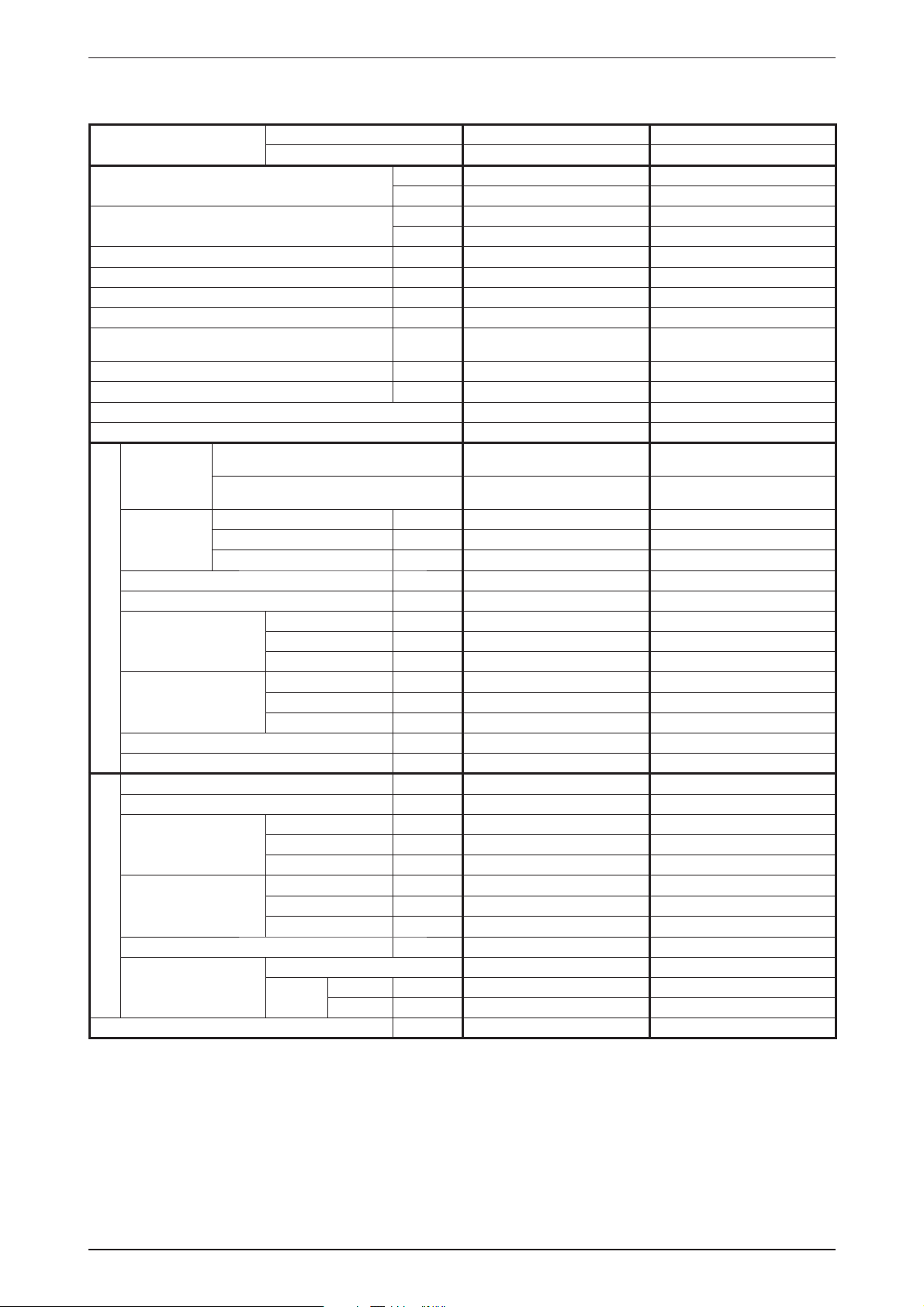
Engineering & Physical Data ACK-E-2009
General Data - Heat Pump (R410A)
MODEL
NOMINAL COOLING CAPACITY - 1Ø / <3Ø>
NOMINAL HEATING CAPACITY - 1Ø / <3Ø>
NOMINAL TOTAL INPUT POWER (COOLING) - 1Ø / <3Ø> W 2820 / <2770> 3920/ <3840>
NOMINAL TOTAL INPUT POWER (HEATING) - 1Ø / <3Ø> W 2550 / <2550> 3740 / <3610>
NOMINAL RUNNING CURRENT (COOLING) - 1Ø / <3Ø> A 13.6 / <5.2> 17.8 / <6.9>
NOMINAL RUNNING CURRENT (HEATING) - 1Ø / <3Ø> A 12.7 / <5.0> 17.2 / <6.6>
POWER SOURCE - 1Ø <3Ø>
EER - 1Ø / <3Ø> W/W 3.03 / <3.28> 2.92 / <2.98>
COP - 1Ø / <3Ø> W/W 3.66 / <3.84> 3.06 / <3.21>
REFRIGERANT TYPE R410A R410A
REFRIGERANT CONTROL (EXPANSION DEVICE) OUTDOOR CAP. TUBE OUTDOOR CAP. TUBE
AIR DISCHARGE
CONTROL
OPERATION
HIGH l/s / CFM 490 / 1030 490 / 1030
AIR FLOW
EXTERNAL STATIC PRESSURE (H/M/L) Pa (in.wg.) 00
SOUND PRESSURE LEVEL (H/M/L) dBA 44 / 41 / 38 44 / 41 / 38
UNIT DIMENSION
INDOOR UNIT
( ) - WITH PANEL
PACKING DIMENSION
( ) - PANEL
WEIGHT (UNIT + PANEL) kg/lb 42+6 / 92.6+13.2 42+6 / 92.6+13.2
CONDENSATE DRAIN SIZE mm/in 19.1 / 0.75 19.1 / 0.75
AIR FLOW l/s / CFM 1605 / 3400 1605 / 3400
SOUND PRESSURE LEVEL dBA 58 58
UNIT DIMENSION
PACKING DIMENSION
OUTDOOR UNIT
UNIT WEIGHT kg/lb 95 / 209 100 / 221
PIPE CONNECTION
REFRIGERANT CHARGE kg/lb 2.175 / 4.80 / <2.15 / 4.74> 2.45 / 5.40 / <2.425 / 4.35>
1) ALL SPECIFICATIONS ARE SUBJECTED TO CHANGE BY THE MANUFACTURER WITHOUT PRIOR NOTICE.
2) ALL UNITS ARE BEING TESTED AND COMPLY TO ISO 5151.
3) NOMINAL COOLING AND HEATING CAPACITY ARE BASED ON THE CONDITIONS BELOW :
a) COOLING - 27°C DB / 19°C WB INDOOR AND 35°C DB / 24°C WB OUTDOOR
b) HEATING - 20°C DB INDOOR AND 7°C DB / 6°C WB OUTDOOR
4) SOUND PRESSURE LEVEL ARE ACCORDING TO JIS C 8615 STANDARD. POSITION OF THE MEASUREMENT POINT IS 1.5m BELOW FASCIA.
MEDIUM l/s / CFM 410 / 860 410 / 860
LOW l/s / CFM 350 / 740 350 / 740
INDOOR UNIT A5CK 40ER A5CK 40ER
OUTDOOR UNIT A5LC 35CR A5LC 40CR
Btu/h 29200 / <31000> 39000 / <39000>
W 8558 / <9086> 11430 / <11430>
Btu/h 31800 / <33400> 39000 / <39500>
W 9320 / <9789> 11430 / <11577>
V/Ph/Hz
HEIGHT mm/in 300 (375) / 11.81 (14.76) 300 (375) / 11.81 (14.76)
WIDTH mm/in 820 (990) / 32.3 (38.98) 820 (990) / 32.3 (38.98)
DEPTH mm/in 820(990) / 32.3 (38.98) 820(990) / 32.3 (38.98)
HEIGHT mm/in 335 (110) / 13.19 (4.3) 335 (110) / 13.19 (4.3)
WIDTH mm/in 916 (1030) / 36.1 (40.6) 916 (1030) / 36.1 (40.6)
DEPTH mm/in 916 (1030) / 36.1 (40.6) 916 (1030) / 36.1 (40.6)
HEIGHT mm/in 850 / 33.5 850 / 33.5
WIDTH mm/in 1030 / 40.6 1030 / 40.6
DEPTH mm/in 400 / 15.8 400 / 15.8
HEIGHT
WIDTH mm/in 1200 / 47.2 1200 / 47.2
DEPTH mm/in 560 / 22.1 560 / 22.1
TYPE FLARE VALVE FLARE VALVE
SIZE
LIQUID mm/in 9.51 / 3/8 9.5 / 3/8
GAS mm/in 15.9 / 5/8 15.9 / 5/8
mm/in 1000 / 39.4 1000 / 39.4
220 - 240 / 1 / 50 /
<380 - 415 / 3 / 50>
4 WAY AUTOMATIC LOUVER
(UP & DOWN)
WIRELESS OR WIRED MICRO-
COMPUTER REMOTE CONTROL
220 - 240 / 1 / 50 /
<380 - 415 / 3 / 50>
4 WAY AUTOMATIC LOUVER
(UP & DOWN)
WIRELESS OR WIRED MICRO-
COMPUTER REMOTE CONTROL
51
Page 54

ACK-E-2009 Engineering & Physical Data
General Data - Heat Pump (R410A)
MODEL
NOMINAL COOLING CAPACITY
NOMINAL HEATING CAPACITY
NOMINAL TOTAL INPUT POWER (COOLING) W 4390
NOMINAL TOTAL INPUT POWER (HEATING) W 4010
NOMINAL RUNNING CURRENT (COOLING) A 7.6
NOMINAL RUNNING CURRENT (HEATING) A 7.2
POWER SOURCE V/Ph/Hz 380 - 415 / 3 / 50
EER W/W 2.87
COP W/W 3.46
REFRIGERANT TYPE R410A
REFRIGERANT CONTROL (EXPANSION DEVICE) OUTDOOR CAP. TUBE
AIR DISCHARGE
CONTROL
OPERATION
HIGH l/s / CFM 570 / 1200
AIR FLOW
EXTERNAL STATIC PRESSURE (H/M/L) Pa (in.wg.) 0
SOUND PRESSURE LEVEL (H/M/L) dBA 47 / 44 / 43
UNIT DIMENSION
INDOOR UNIT
( ) - WITH PANEL
PACKING DIMENSION
( ) - PANEL
WEIGHT (UNIT + PANEL) kg/lb 42+6 / 92.6+13.2
CONDENSATE DRAIN SIZE mm/in 19.1 / 0.75
AIR FLOW l/s / CFM 2171 / 4600
SOUND PRESSURE LEVEL dBA 68
UNIT DIMENSION
PACKING DIMENSION
OUTDOOR UNIT
UNIT WEIGHT kg/lb 105 / 232
PIPE CONNECTION
REFRIGERANT CHARGE kg/lb 2.3 / 5.07
1) ALL SPECIFICATIONS ARE SUBJECTED TO CHANGE BY THE MANUFACTURER WITHOUT PRIOR NOTICE.
2) ALL UNITS ARE BEING TESTED AND COMPLY TO ISO 5151.
3) NOMINAL COOLING AND HEATING CAPACITY ARE BASED ON THE CONDITIONS BELOW :
a) COOLING - 27°C DB / 19°C WB INDOOR AND 35°C DB / 24°C WB OUTDOOR
b) HEATING - 20°C DB INDOOR AND 7°C DB / 6°C WB OUTDOOR
4) SOUND PRESSURE LEVEL ARE ACCORDING TO JIS C 8615 STANDARD. POSITION OF THE MEASUREMENT POINT IS 1.5m BELOW FASCIA.
MEDIUM l/s / CFM 490 / 1030
LOW l/s / CFM 440 / 930
INDOOR UNIT A5CK 50ER
OUTDOOR UNIT A5LC 50CR
Btu/h 43000
W 12603
Btu/h 47300
W 13863
4 WAY AUTOMATIC LOUVER
(UP & DOWN)
WIRELESS OR WIRED MICRO-
COMPUTER REMOTE CONTROL
HEIGHT mm/in 300 (375) / 11.81 (14.76)
WIDTH mm/in 820 (990) / 32.3 (38.98)
DEPTH mm/in 820(990) / 32.3 (38.98)
HEIGHT mm/in 335 (110) / 13.19 (4.3)
WIDTH mm/in 916 (1030) / 36.1 (40.6)
DEPTH mm/in 916 (1030) / 36.1 (40.6)
HEIGHT mm/in 850 / 33.5
WIDTH mm/in 1030 / 40.6
DEPTH mm/in 400 / 15.8
HEIGHT
WIDTH mm/in 1200 / 47.2
DEPTH
TYPE FLARE VALVE
SIZE
LIQUID mm/in 9.5 / 3/8
GAS mm/in 15.9 / 5/8
mm/in 1000 / 39.4
mm/in 560 / 22.1
52
Page 55

Engineering & Physical Data ACK-E-2009
Component Data - Cooling Only (R22)
MODEL
INDOOR UNIT ACK 20E ACK 25E
OUTDOOR UNIT ALC 20C ALC 25C
TYPE BLOWER WHEEL BLOWER WHEEL
QUANTITY 11
INDOOR FAN
MATERIAL ASG 10% ASG 10%
DRIVE DIRECT DIRECT
DIAMETER
LENGTH
mm/in
mm/in
462 / 18.18 462 / 18.18
171 / 6.13 171 / 6.13
TYPE INDUCTION INDUCTION
INDOOR FAN MOTOR
QUANTITY 11
INDEX OF PROTECTION (IP) 20 20
TYPE PROPELLER PROPELLER
QUANTITY 11
OUTDOOR FAN
MATERIAL
GLASS REINFORCED ACRYL
STYRENE RESIN
DRIVE DIRECT DIRECT
DIAMETER
mm/in
457 / 18 457 / 18
TYPE INDUCTION INDUCTION
OUTDOOR FAN
MOTOR
QUANTITY 11
INDEX OF PROTECTION (IP) IP54 IP54
TYPE ROTARY ROTARY
COMPRESSOR
INDOOR COIL
OIL TYPE ATMOS NM56M or SUNISO 4GDID ATMOS NM56M or SUNISO 4GDID
OIL AMOUNT
MATERIAL
TUBE
DIAMETER
THICKNESS
cm
mm/in
mm/in
3
/ fl .oz.
670 / 23.6 670 / 23.6
SEAMLESS INNER GROOVED COPPER SEAMLESS INNER GROOVED COPPER
7 / 0.27 7 / 0.27
0.24 / 0.01 0.24 / 0.01
MATERIAL ALUMINIUM (SLIT FIN) ALUMINIUM (SLIT FIN)
FIN
THICKNESS
FACE AREA
mm/in
2
m
/ft
2
0.11 / 0.004 0.11 / 0.004
0.386 / 4.15 0.386 / 4.15
ROW 22
FIN PER INCH 18 18
SEAMLESS INNER GROOVE COPPER SEAMLESS INNER GROOVE COPPER
7.00 / 0.276 7.00 / 0.276
0.28 / 0.011 0.28 / 0.011
0.10 / 0.004 0.10 / 0.004
2
2
/ft
0.52 / 5.59 0.52 / 5.59
OUTDOOR COIL
TUBE
FIN
MATERIAL
DIAMETER
THICKNESS
mm/in
mm/in
MATERIAL ALUMINIUM (RAISE LANCE) ALUMINIUM (RAISE LANCE)
THICKNESS
FACE AREA
mm/in
m
ROW 12
FIN PER INCH 20 24
TYPE WASHABLE SARANET FILTER WASHABLE SARANET FILTER
AIR QUALITY FILTER
PAN EL
CASING
INDOOR UNIT
OUTDOOR UNIT
QUANTITY
LENGTH
WIDTH
SIZE
THICKNESS
pc
mm/in
mm/in
mm/in
MATERIAL
FINISHING
COLOUR
MATERIAL
FINISHING
COLOUR
MATERIAL
FINISHING
COLOUR
HOT DIP GALVANIZED STEEL HOT DIP GALVANIZED STEEL
WITH PE INSULATION WITH PE INSULATION
GALVANIZED MILD STEEL GALVANIZED MILD STEEL
POLYESTER POWDER POLYESTER POWDER
11
576.0 / 22.7 576.0 / 22.7
556.0 / 21.9 556.0 / 21.9
2 / 0.078 2 / 0.078
ABS ABS
N/A N/A
LIGHT GREY LIGHT GREY
WITHOUT PAINT WITHOUT PAINT
LIGHT GREY LIGHT GREY
1) ALL SPECIFICATIONS ARE SUBJECTED TO CHANGE BY THE MANUFACTURER WITHOUT PRIOR NOTICE.
GLASS REINFORCED ACRYL
STYRENE RESIN
53
Page 56

ACK-E-2009 Engineering & Physical Data
Component Data - Cooling Only (R22)
MODEL
INDOOR UNIT ACK 28E
OUTDOOR UNIT ALC 28C
TYPE BLOWER WHEEL
QUANTITY 1
INDOOR FAN
MATERIAL ASG 10%
DRIVE DIRECT
DIAMETER
LENGTH
mm/in
mm/in
462 / 18.18
171 / 6.13
TYPE INDUCTION
INDOOR FAN MOTOR
QUANTITY 1
INDEX OF PROTECTION (IP) 20
TYPE PROPELLER
QUANTITY 1
OUTDOOR FAN
MATERIAL
GLASS REINFORCED ACRYL
STYRENE RESIN
DRIVE DIRECT
DIAMETER
mm/in
457 / 18
TYPE INDUCTION
OUTDOOR FAN
MOTOR
QUANTITY 1
INDEX OF PROTECTION (IP) IP54
TYPE ROTARY
COMPRESSOR
INDOOR COIL
OIL TYPE ATMOS M60 or SUNISO 4GDID
OIL AMOUNT
MATERIAL
TUBE
DIAMETER
THICKNESS
cm
mm/in
mm/in
3
/ fl .oz.
1130 / 39.8
SEAMLESS INNER GROOVED COPPER
7 / 0.27
0.24 / 0.01
MATERIAL ALUMINIUM (SLIT FIN)
FIN
THICKNESS
FACE AREA
mm/in
2
m
/ft
2
0.11 / 0.004
0.372 / 4.0
ROW 3
FIN PER INCH 18
SEAMLESS INNER GROOVE COPPER
9.52 / 3/8
0.33 / 0.013
0.12 / 0.005
2
2
/ft
0.61 / 6.52
OUTDOOR COIL
TUBE
FIN
MATERIAL
DIAMETER
THICKNESS
mm/in
mm/in
MATERIAL ALUMINIUM (SLIT FIN)
THICKNESS
FACE AREA
mm/in
m
ROW 2
FIN PER INCH 18
TYPE WASHABLE SARANET FILTER
AIR QUALITY FILTER
PAN EL
CASING
INDOOR UNIT
OUTDOOR UNIT
QUANTITY
LENGTH
WIDTH
SIZE
THICKNESS
pc
mm/in
mm/in
mm/in
MATERIAL
FINISHING
COLOUR
MATERIAL
FINISHING
COLOUR
MATERIAL
FINISHING
COLOUR
HOT DIP GALVANIZED STEEL
WITH PE INSULATION
GALVANIZED MILD STEEL
POLYESTER POWDER
1
576.0 / 22.7
556.0 / 21.9
2 / 0.078
ABS
N/A
LIGHT GREY
WITHOUT PAINT
LIGHT GREY
1) ALL SPECIFICATIONS ARE SUBJECTED TO CHANGE BY THE MANUFACTURER WITHOUT PRIOR NOTICE.
54
Page 57

Engineering & Physical Data ACK-E-2009
Component Data - Cooling Only (R22)
MODEL
INDOOR UNIT ACK 40E ACK 40E
OUTDOOR UNIT ALC 35C ALC 40C
TYPE BLOWER WHEEL BLOWER WHEEL
QUANTITY 11
INDOOR FAN
MATERIAL ASG 10% ASG 10%
DRIVE DIRECT DIRECT
DIAMETER
LENGTH
mm/in
mm/in
462 / 18.18 462 / 18.18
171 / 6.13 171 / 6.13
TYPE INDUCTION INDUCTION
INDOOR FAN MOTOR
QUANTITY 11
INDEX OF PROTECTION (IP) 20 20
TYPE PROPELLER PROPELLER
QUANTITY 11
OUTDOOR FAN
MATERIAL
GLASS REINFORCED ACRYL
STYRENE RESIN
DRIVE DIRECT DIRECT
DIAMETER
mm/in
609.6 / 24 609.6 / 24
TYPE INDUCTION INDUCTION
OUTDOOR FAN
MOTOR
QUANTITY 11
INDEX OF PROTECTION (IP) --
TYPE SCROLL SCROLL
COMPRESSOR
INDOOR COIL
OIL TYPE MINERAL (Sontex 200 LT) MINERAL (Sontex 200 LT)
OIL AMOUNT
MATERIAL
TUBE
DIAMETER
THICKNESS
cm
mm/in
mm/in
3
/ fl .oz.
1240 / 43.6 1240 / 43.6
SEAMLESS INNER GROOVED COPPER SEAMLESS INNER GROOVED COPPER
7 / 0.27 7 / 0.27
0.24 / 0.01 0.24 / 0.01
MATERIAL ALUMINIUM (SLIT FIN) ALUMINIUM (SLIT FIN)
FIN
THICKNESS
FACE AREA
mm/in
2
m
/ft
2
0.11 / 0.004 0.11 / 0.004
0.461 / 4.96 0.461 / 4.96
ROW 33
FIN PER INCH 20 20
MATERIAL SEAMLESS COPPER SEAMLESS COPPER
OUTDOOR COIL
TUBE
FIN
DIAMETER
THICKNESS
mm/in
mm/in
MATERIAL ALUMINIUM (SLIT FIN) ALUMINIUM (CORR. FIN)
THICKNESS
FACE AREA
mm/in
m2/ft
2
9.52 / 3/8 9.52 / 3/8
0.35 / 0.014 0.35 / 0.014
0.127 / 0.005 0.127 / 0.005
0.87 / 9.33 0.87 / 9.33
ROW 12
FIN PER INCH 16 14
TYPE WASHABLE SARANET FILTER WASHABLE SARANET FILTER
AIR QUALITY FILTER
PAN EL
CASING
INDOOR UNIT
OUTDOOR UNIT
QUANTITY
LENGTH
WIDTH
SIZE
THICKNESS
pc
mm/in
mm/in
mm/in
MATERIAL
FINISHING
COLOUR
MATERIAL
FINISHING
COLOUR
MATERIAL
FINISHING
COLOUR
HOT DIP GALVANIZED STEEL HOT DIP GALVANIZED STEEL
WITH PE INSULATION WITH PE INSULATION
GALVANIZED MILD STEEL GALVANIZED MILD STEEL
POLYESTER POWDER POLYESTER POWDER
11
576.0 / 22.7 576.0 / 22.7
556.0 / 21.9 556.0 / 21.9
2 / 0.078 2 / 0.078
ABS ABS
N/A N/A
LIGHT GREY LIGHT GREY
WITHOUT PAINT WITHOUT PAINT
LIGHT GREY LIGHT GREY
1) ALL SPECIFICATIONS ARE SUBJECTED TO CHANGE BY THE MANUFACTURER WITHOUT PRIOR NOTICE.
GLASS REINFORCED ACRYL
STYRENE RESIN
55
Page 58

ACK-E-2009 Engineering & Physical Data
Component Data - Cooling Only (R22)
MODEL
INDOOR UNIT ACK 50E
OUTDOOR UNIT ALC 50C
TYPE BLOWER WHEEL
QUANTITY 1
INDOOR FAN
MATERIAL ASG 10%
DRIVE DIRECT
DIAMETER
LENGTH
mm/in
mm/in
462 / 18.18
171 / 6.13
TYPE INDUCTION
INDOOR FAN MOTOR
QUANTITY 1
INDEX OF PROTECTION (IP) 20
TYPE PROPELLER
QUANTITY 1
OUTDOOR FAN
MATERIAL
GLASS REINFORCED ACRYL
STYRENE RESIN
DRIVE DIRECT
DIAMETER
mm/in
609.6 / 24
TYPE PROPELLER
OUTDOOR FAN
MOTOR
QUANTITY 1
INDEX OF PROTECTION (IP) -
TYPE SCROLL
COMPRESSOR
INDOOR COIL
OIL TYPE MINERAL (Sontex 200 LT)
OIL AMOUNT
MATERIAL
TUBE
DIAMETER
THICKNESS
cm
mm/in
mm/in
3
/ fl .oz.
1950 / 68.6
SEAMLESS INNER GROOVED COPPER
7 / 0.27
0.24 / 0.01
MATERIAL ALUMINIUM (SLIT FIN)
FIN
THICKNESS
FACE AREA
mm/in
2
m
/ft
2
0.11 / 0.004
0.464 / 4.988
ROW 3
FIN PER INCH 20
MATERIAL SEAMLESS COPPER
OUTDOOR COIL
TUBE
FIN
DIAMETER
THICKNESS
mm/in
mm/in
MATERIAL ALUMINIUM (CORR. FIN)
THICKNESS
FACE AREA
mm/in
m2/ft
2
9.52 / 3/8
0.35 / 0.014
0.127 / 0.005
0.87 / 9.33
ROW 2
FIN PER INCH 16
TYPE WASHABLE SARANET FILTER
AIR QUALITY FILTER
PAN EL
CASING
INDOOR UNIT
OUTDOOR UNIT
QUANTITY
LENGTH
WIDTH
SIZE
THICKNESS
pc
mm/in
mm/in
mm/in
MATERIAL
FINISHING
COLOUR
MATERIAL
FINISHING
COLOUR
MATERIAL
FINISHING
COLOUR
HOT DIP GALVANIZED STEEL
WITH PE INSULATION
GALVANIZED MILD STEEL
POLYESTER POWDER
1
576.0 / 22.7
556.0 / 21.9
2 / 0.078
ABS
N/A
LIGHT GREY
WITHOUT PAINT
LIGHT GREY
1) ALL SPECIFICATIONS ARE SUBJECTED TO CHANGE BY THE MANUFACTURER WITHOUT PRIOR NOTICE.
56
Page 59

Engineering & Physical Data ACK-E-2009
Component Data - Heat Pump (R22)
MODEL
INDOOR UNIT ACK 20ER ACK 25ER
OUTDOOR UNIT ALC 20CR ALC 25CR
TYPE BLOWER WHEEL BLOWER WHEEL
QUANTITY 11
INDOOR FAN
MATERIAL ASG 10% ASG 10%
DRIVE DIRECT DIRECT
DIAMETER
LENGTH
mm/in
mm/in
462 / 18.18 462 / 18.18
171 / 6.13 171 / 6.13
TYPE INDUCTION INDUCTION
INDOOR FAN MOTOR
QUANTITY 11
INDEX OF PROTECTION (IP) 20 20
TYPE PROPELLER PROPELLER
QUANTITY 11
OUTDOOR FAN
MATERIAL
GLASS REINFORCED ACRYL
STYRENE RESIN
DRIVE DIRECT DIRECT
DIAMETER
mm/in
457 / 18 457 / 18
TYPE INDUCTION INDUCTION
OUTDOOR FAN
MOTOR
QUANTITY 11
INDEX OF PROTECTION (IP) IP54 IP54
TYPE ROTARY ROTARY
COMPRESSOR
INDOOR COIL
OIL TYPE ATMOS NM56M or SUNISO 4GDID ATMOS NM56M or SUNISO 4GDID
OIL AMOUNT
MATERIAL
TUBE
DIAMETER
THICKNESS
cm
mm/in
mm/in
3
/ fl .oz.
670 / 23.6 670 / 23.6
SEAMLESS INNER GROOVED COPPER SEAMLESS INNER GROOVED COPPER
7 / 0.27 7 / 0.27
0.24 / 0.01 0.24 / 0.01
MATERIAL ALUMINIUM (SLIT FIN) ALUMINIUM (SLIT FIN)
FIN
THICKNESS
FACE AREA
mm/in
2
m
/ft
2
0.11 / 0.004 0.11 / 0.004
0.386 / 4.15 0.386 / 4.15
ROW 22
FIN PER INCH 18 18
SEAMLESS INNER GROOVE COPPER SEAMLESS INNER GROOVE COPPER
7.00 / 0.276 7.00 / 0.276
0.28 / 0.011 0.28 / 0.011
0.10 / 0.004 0.10 / 0.004
2
2
/ft
0.52 / 5.59 0.52 / 5.59
OUTDOOR COIL
TUBE
FIN
MATERIAL
DIAMETER
THICKNESS
mm/in
mm/in
MATERIAL ALUMINIUM (RAISE LANCE) ALUMINIUM (RAISE LANCE)
THICKNESS
FACE AREA
mm/in
m
ROW 12
FIN PER INCH 20 24
TYPE WASHABLE SARANET FILTER WASHABLE SARANET FILTER
AIR QUALITY FILTER
PAN EL
CASING
INDOOR UNIT
OUTDOOR UNIT
QUANTITY
LENGTH
WIDTH
SIZE
THICKNESS
pc
mm/in
mm/in
mm/in
MATERIAL
FINISHING
COLOUR
MATERIAL
FINISHING
COLOUR
MATERIAL
FINISHING
COLOUR
HOT DIP GALVANIZED STEEL HOT DIP GALVANIZED STEEL
WITH PE INSULATION WITH PE INSULATION
GALVANIZED MILD STEEL GALVANIZED MILD STEEL
POLYESTER POWDER POLYESTER POWDER
11
576.0 / 22.7 576.0 / 22.7
556.0 / 21.9 556.0 / 21.9
2 / 0.078 2 / 0.078
ABS ABS
N/A N/A
LIGHT GREY LIGHT GREY
WITHOUT PAINT WITHOUT PAINT
LIGHT GREY LIGHT GREY
1) ALL SPECIFICATIONS ARE SUBJECTED TO CHANGE BY THE MANUFACTURER WITHOUT PRIOR NOTICE.
GLASS REINFORCED ACRYL
STYRENE RESIN
57
Page 60

ACK-E-2009 Engineering & Physical Data
Component Data - Heat Pump (R22)
MODEL
INDOOR UNIT ACK 28ER ACK 28ER
OUTDOOR UNIT ALC 28CR ALC 28CR
TYPE BLOWER WHEEL BLOWER WHEEL
QUANTITY 11
INDOOR FAN
MATERIAL ASG 10% ASG 10%
DRIVE DIRECT DIRECT
DIAMETER
LENGTH
mm/in
mm/in
462 / 18.18 462 / 18.18
171 / 6.13 171 / 6.13
TYPE INDUCTION INDUCTION
INDOOR FAN MOTOR
QUANTITY 11
INDEX OF PROTECTION (IP) 20 20
TYPE PROPELLER PROPELLER
QUANTITY 11
OUTDOOR FAN
MATERIAL
GLASS REINFORCED ACRYL
STYRENE RESIN
DRIVE DIRECT DIRECT
DIAMETER
mm/in
457 / 18 609.6 / 24
TYPE INDUCTION INDUCTION
OUTDOOR FAN
MOTOR
QUANTITY 11
INDEX OF PROTECTION (IP) IP54 IP54
TYPE ROTARY ROTARY
COMPRESSOR
INDOOR COIL
OIL TYPE ATMOS M60 or SUNISO 4GDID ATMOS M60 or SUNISO 4GDID
OIL AMOUNT
MATERIAL
TUBE
DIAMETER
THICKNESS
cm
mm/in
mm/in
3
/ fl .oz.
1130 / 39.8 1130 / 39.8
SEAMLESS INNER GROOVED COPPER SEAMLESS INNER GROOVED COPPER
7 / 0.27 7 / 0.27
0.24 / 0.01 0.24 / 0.01
MATERIAL ALUMINIUM (SLIT FIN) ALUMINIUM (SLIT FIN)
FIN
THICKNESS
FACE AREA
mm/in
2
m
/ft
2
0.11 / 0.004 0.11 / 0.004
0.372 / 4.0 0.372 / 4.0
ROW 33
FIN PER INCH 18 18
SEAMLESS INNER GROOVE COPPER SEAMLESS INNER GROOVE COPPER
9.52 / 3/8 9.52 / 3/8
0.33 / 0.013 0.33 / 0.013
0.12 / 0.005 0.12 / 0.005
2
2
/ft
0.61 / 6.52 0.61 / 6.52
OUTDOOR COIL
TUBE
FIN
MATERIAL
DIAMETER
THICKNESS
mm/in
mm/in
MATERIAL ALUMINIUM (SLIT FIN) ALUMINIUM (SLIT FIN)
THICKNESS
FACE AREA
mm/in
m
ROW 22
FIN PER INCH 18 18
TYPE WASHABLE SARANET FILTER WASHABLE SARANET FILTER
AIR QUALITY FILTER
PAN EL
CASING
INDOOR UNIT
OUTDOOR UNIT
QUANTITY
LENGTH
WIDTH
SIZE
THICKNESS
pc
mm/in
mm/in
mm/in
MATERIAL
FINISHING
COLOUR
MATERIAL
FINISHING
COLOUR
MATERIAL
FINISHING
COLOUR
HOT DIP GALVANIZED STEEL HOT DIP GALVANIZED STEEL
WITH PE INSULATION WITH PE INSULATION
GALVANIZED MILD STEEL GALVANIZED MILD STEEL
POLYESTER POWDER POLYESTER POWDER
11
576.0 / 22.7 576.0 / 22.7
556.0 / 21.9 556.0 / 21.9
2 / 0.078 2 / 0.078
ABS ABS
N/A N/A
LIGHT GREY LIGHT GREY
WITHOUT PAINT WITHOUT PAINT
LIGHT GREY LIGHT GREY
1) ALL SPECIFICATIONS ARE SUBJECTED TO CHANGE BY THE MANUFACTURER WITHOUT PRIOR NOTICE.
GLASS REINFORCED ACRYL
STYRENE RESIN
58
Page 61

Engineering & Physical Data ACK-E-2009
Component Data - Heat Pump (R22)
MODEL
INDOOR UNIT ACK 40ER ACK 40ER
OUTDOOR UNIT ALC 35CR ALC 40CR
TYPE BLOWER WHEEL BLOWER WHEEL
QUANTITY 11
INDOOR FAN
MATERIAL ASG 10% ASG 10%
DRIVE DIRECT DIRECT
DIAMETER
LENGTH
mm/in
mm/in
462 / 18.18 462 / 18.18
171 / 6.13 171 / 6.13
TYPE INDUCTION INDUCTION
INDOOR FAN MOTOR
QUANTITY 11
INDEX OF PROTECTION (IP) 20 20
TYPE PROPELLER PROPELLER
QUANTITY 11
OUTDOOR FAN
MATERIAL
GLASS REINFORCED ACRYL
STYRENE RESIN
DRIVE DIRECT DIRECT
DIAMETER
mm/in
609.6 / 24 609.6 / 24
TYPE INDUCTION INDUCTION
OUTDOOR FAN
MOTOR
QUANTITY 11
INDEX OF PROTECTION (IP) --
TYPE SCROLL SCROLL
COMPRESSOR
INDOOR COIL
OIL TYPE MINERAL (Sontex 200 LT) MINERAL (Sontex 200 LT)
OIL AMOUNT
MATERIAL
TUBE
DIAMETER
THICKNESS
cm
mm/in
mm/in
3
/ fl .oz.
1240 / 43.6 1240 / 43.6
SEAMLESS INNER GROOVED COPPER SEAMLESS INNER GROOVED COPPER
7 / 0.27 7 / 0.27
0.24 / 0.01 0.24 / 0.01
MATERIAL ALUMINIUM (SLIT FIN) ALUMINIUM (SLIT FIN)
FIN
THICKNESS
FACE AREA
mm/in
2
m
/ft
2
0.11 / 0.004 0.11 / 0.004
0.461 / 4.96 0.461 / 4.96
ROW 33
FIN PER INCH 20 20
SEAMLESS INNER GROOVED COPPER SEAMLESS INNER GROOVED COPPER
9.52 / 3/8 9.52 / 3/8
0.33 / 0.013 0.33 / 0.013
0.127 / 0.005 0.127 / 0.005
2
2
/ft
0.87 / 9.33 0.87 / 9.33
OUTDOOR COIL
TUBE
FIN
MATERIAL
DIAMETER
THICKNESS
mm/in
mm/in
MATERIAL ALUMINIUM (CORR. FIN) ALUMINIUM (CORR. FIN)
THICKNESS
FACE AREA
mm/in
m
ROW 22
FIN PER INCH 16 16
TYPE WASHABLE SARANET FILTER WASHABLE SARANET FILTER
AIR QUALITY FILTER
PAN EL
CASING
INDOOR UNIT
OUTDOOR UNIT
QUANTITY
LENGTH
WIDTH
SIZE
THICKNESS
pc
mm/in
mm/in
mm/in
MATERIAL
FINISHING
COLOUR
MATERIAL
FINISHING
COLOUR
MATERIAL
FINISHING
COLOUR
HOT DIP GALVANIZED STEEL HOT DIP GALVANIZED STEEL
WITH PE INSULATION WITH PE INSULATION
GALVANIZED MILD STEEL GALVANIZED MILD STEEL
POLYESTER POWDER POLYESTER POWDER
11
576.0 / 22.7 576.0 / 22.7
556.0 / 21.9 556.0 / 21.9
2 / 0.078 2 / 0.078
ABS ABS
N/A N/A
LIGHT GREY LIGHT GREY
WITHOUT PAINT WITHOUT PAINT
LIGHT GREY LIGHT GREY
1) ALL SPECIFICATIONS ARE SUBJECTED TO CHANGE BY THE MANUFACTURER WITHOUT PRIOR NOTICE.
GLASS REINFORCED ACRYL
STYRENE RESIN
59
Page 62

ACK-E-2009 Engineering & Physical Data
Component Data - Heat Pump (R22)
MODEL
INDOOR UNIT ACK 50ER
OUTDOOR UNIT ALC 50CR
TYPE BLOWER WHEEL
QUANTITY 1
INDOOR FAN
MATERIAL ASG 10%
DRIVE DIRECT
DIAMETER
LENGTH
mm/in
mm/in
462 / 18.18
171 / 6.13
TYPE INDUCTION
INDOOR FAN MOTOR
QUANTITY 1
INDEX OF PROTECTION (IP) 20
TYPE PROPELLER
QUANTITY 1
OUTDOOR FAN
MATERIAL
GLASS REINFORCED ACRYL
STYRENE RESIN
DRIVE DIRECT
DIAMETER
mm/in
609.6 / 24
TYPE INDUCTION
OUTDOOR FAN
MOTOR
QUANTITY 1
INDEX OF PROTECTION (IP) -
TYPE SCROLL
COMPRESSOR
INDOOR COIL
OIL TYPE MINERAL (Sontex 200 LT)
OIL AMOUNT
MATERIAL
TUBE
DIAMETER
THICKNESS
cm
mm/in
mm/in
3
/ fl .oz.
1950 / 68.6
SEAMLESS INNER GROOVED COPPER
7 / 0.27
0.24 / 0.01
MATERIAL ALUMINIUM (SLIT FIN)
FIN
THICKNESS
FACE AREA
mm/in
2
m
/ft
2
0.11 / 0.004
0.464 / 4.988
ROW 3
FIN PER INCH 20
SEAMLESS INNER GROOVED COPPER
9.52 / 3/8
0.33 / 0.013
0.127 / 0.005
2
2
/ft
0.87 / 9.33
OUTDOOR COIL
TUBE
FIN
MATERIAL
DIAMETER
THICKNESS
mm/in
mm/in
MATERIAL ALUMINIUM (CORR. FIN)
THICKNESS
FACE AREA
mm/in
m
ROW 2
FIN PER INCH 16
TYPE WASHABLE SARANET FILTER
AIR QUALITY FILTER
PAN EL
CASING
INDOOR UNIT
OUTDOOR UNIT
QUANTITY
LENGTH
WIDTH
SIZE
THICKNESS
pc
mm/in
mm/in
mm/in
MATERIAL
FINISHING
COLOUR
MATERIAL
FINISHING
COLOUR
MATERIAL
FINISHING
COLOUR
HOT DIP GALVANIZED STEEL
WITH PE INSULATION
GALVANIZED MILD STEEL
POLYESTER POWDER
1
576.0 / 22.7
556.0 / 21.9
2 / 0.078
ABS
N/A
LIGHT GREY
WITHOUT PAINT
LIGHT GREY
1) ALL SPECIFICATIONS ARE SUBJECTED TO CHANGE BY THE MANUFACTURER WITHOUT PRIOR NOTICE.
60
Page 63

Engineering & Physical Data ACK-E-2009
Component Data - Cooling Only (R410A)
MODEL
INDOOR UNIT A5CK 20E A5CK 25E
OUTDOOR UNIT A5LC 20C A5LC 25C
TYPE BLOWER WHEEL BLOWER WHEEL
QUANTITY 11
INDOOR FAN
MATERIAL ASG 10% ASG 10%
DRIVE DIRECT DIRECT
DIAMETER
LENGTH
mm/in
mm/in
462 / 18.18 462 / 18.18
171 / 6.13 171 / 6.13
TYPE INDUCTION INDUCTION
INDOOR FAN MOTOR
QUANTITY 11
INDEX OF PROTECTION (IP) 20 20
TYPE PROPELLER PROPELLER
QUANTITY 11
OUTDOOR FAN
MATERIAL
GLASS REINFORCED ACRYL
STYRENE RESIN
DRIVE DIRECT DIRECT
DIAMETER
mm/in
457 / 18 457 / 18
TYPE INDUCTION INDUCTION
OUTDOOR FAN
MOTOR
QUANTITY 11
INDEX OF PROTECTION (IP) IP54 IP54
TYPE ROTARY ROTARY
COMPRESSOR
INDOOR COIL
OIL TYPE RB68A or Freol Alpha68M RB68A or Freol Alpha68M
OIL AMOUNT
MATERIAL
TUBE
DIAMETER
THICKNESS
cm
mm/in
mm/in
3
/ fl .oz.
670 / 23.6 1130 / 39.8
SEAMLESS INNER GROOVED COPPER SEAMLESS INNER GROOVED COPPER
7 / 0.27 7 / 0.27
0.24 / 0.01 0.24 / 0.01
MATERIAL ALUMINIUM (SLIT FIN) ALUMINIUM (SLIT FIN)
FIN
THICKNESS
FACE AREA
mm/in
2
m
/ft
2
0.11 / 0.004 0.11 / 0.004
0.386 / 4.15 0.386 / 4.15
ROW 22
FIN PER INCH 18 18
SEAMLESS INNER GROOVE COPPER SEAMLESS INNER GROOVE COPPER
7.00 / 0.276 7.00 / 0.276
0.28 / 0.011 0.28 / 0.011
0.10 / 0.004 0.10 / 0.004
2
2
/ft
0.510 / 5.460 0.620 / 6.630
OUTDOOR COIL
TUBE
FIN
MATERIAL
DIAMETER
THICKNESS
mm/in
mm/in
MATERIAL ALUMINIUM (RAISE LANCE) ALUMINIUM (RAISE LANCE)
THICKNESS
FACE AREA
mm/in
m
ROW 22
FIN PER INCH 18 18
TYPE WASHABLE SARANET FILTER WASHABLE SARANET FILTER
AIR QUALITY FILTER
PAN EL
CASING
INDOOR UNIT
OUTDOOR UNIT
QUANTITY
LENGTH
WIDTH
SIZE
THICKNESS
pc
mm/in
mm/in
mm/in
MATERIAL
FINISHING
COLOUR
MATERIAL
FINISHING
COLOUR
MATERIAL
FINISHING
COLOUR
HOT DIP GALVANIZED STEEL HOT DIP GALVANIZED STEEL
WITH PE INSULATION WITH PE INSULATION
GALVANIZED MILD STEEL GALVANIZED MILD STEEL
POLYESTER POWDER POLYESTER POWDER
11
576.0 / 22.7 576.0 / 22.7
556.0 / 21.9 556.0 / 21.9
2 / 0.078 2 / 0.078
ABS ABS
N/A N/A
LIGHT GREY LIGHT GREY
WITHOUT PAINT WITHOUT PAINT
LIGHT GREY LIGHT GREY
1) ALL SPECIFICATIONS ARE SUBJECTED TO CHANGE BY THE MANUFACTURER WITHOUT PRIOR NOTICE.
GLASS REINFORCED ACRYL
STYRENE RESIN
61
Page 64

ACK-E-2009 Engineering & Physical Data
Component Data - Cooling Only (R410A)
MODEL
INDOOR UNIT A5CK 28E
OUTDOOR UNIT A5LC 28C
TYPE BLOWER WHEEL
QUANTITY 1
INDOOR FAN
MATERIAL ASG 10%
DRIVE DIRECT
DIAMETER
LENGTH
mm/in
mm/in
462 / 18.18
171 / 6.13
TYPE INDUCTION
INDOOR FAN MOTOR
QUANTITY 1
INDEX OF PROTECTION (IP) IP22
TYPE PROPELLER
QUANTITY 1
OUTDOOR FAN
MATERIAL
GLASS REINFORCED ACRYL
STYRENE RESIN
DRIVE DIRECT
DIAMETER
mm/in
457 / 18
TYPE INDUCTION
OUTDOOR FAN
MOTOR
QUANTITY 1
INDEX OF PROTECTION (IP) IP54
TYPE ROTARY
COMPRESSOR
INDOOR COIL
OIL TYPE RB68A or Freol Alpha68M
OIL AMOUNT
MATERIAL
TUBE
DIAMETER
THICKNESS
cm
mm/in
mm/in
3
/ fl .oz.
SEAMLESS INNER GROOVED COPPER
1130 / 39.8
7 / 0.27
0.24 / 0.01
MATERIAL ALUMINIUM (SLIT FIN)
FIN
THICKNESS
FACE AREA
mm/in
m2/ft
2
0.11 / 0.004
0.372 / 4.0
ROW 3
FIN PER INCH 18
SEAMLESS INNER GROOVE COPPER
7.00 / 0.276
0.28 / 0.011
0.11 / 0.0043
2
2
/ft
0.620 / 6.630
OUTDOOR COIL
TUBE
FIN
MATERIAL
DIAMETER
THICKNESS
mm/in
mm/in
MATERIAL ALUMINIUM (CORR. FIN)
THICKNESS
FACE AREA
mm/in
m
ROW 2
FIN PER INCH 18
TYPE WASHABLE SARANET FILTER
AIR QUALITY FILTER
PAN EL
CASING
INDOOR UNIT
OUTDOOR UNIT
QUANTITY
LENGTH
WIDTH
SIZE
THICKNESS
pc
mm/in
mm/in
mm/in
MATERIAL
FINISHING
COLOUR
MATERIAL
FINISHING
COLOUR
MATERIAL
FINISHING
COLOUR
HOT DIP GALVANIZED STEEL
WITH PE INSULATION
GALVANIZED MILD STEEL
POLYESTER POWDER
1
576.0 / 22.7
556.0 / 21.9
2 / 0.078
ABS
N/A
LIGHT GREY
WITHOUT PAINT
LIGHT GREY
1) ALL SPECIFICATIONS ARE SUBJECTED TO CHANGE BY THE MANUFACTURER WITHOUT PRIOR NOTICE.
62
Page 65

Engineering & Physical Data ACK-E-2009
Component Data - Cooling Only (R410A)
MODEL
INDOOR UNIT A5CK 40E A5CK 40E
OUTDOOR UNIT A5LC 35C A5LC 40C
TYPE BLOWER WHEEL BLOWER WHEEL
QUANTITY 11
INDOOR FAN
MATERIAL ASG 10% ASG 10%
DRIVE DIRECT DIRECT
DIAMETER
LENGTH
mm/in
mm/in
462 / 18.18 462 / 18.18
171 / 6.13 171 / 6.13
TYPE INDUCTION INDUCTION
INDOOR FAN MOTOR
QUANTITY 11
INDEX OF PROTECTION (IP) IP22 IP22
TYPE PROPELLER PROPELLER
QUANTITY 11
OUTDOOR FAN
MATERIAL
GLASS REINFORCED ACRYL
STYRENE RESIN
DRIVE DIRECT DIRECT
DIAMETER
mm/in
609.6 / 24 609.6 / 24
TYPE INDUCTION INDUCTION
OUTDOOR FAN
MOTOR
QUANTITY 11
INDEX OF PROTECTION (IP) --
TYPE SCROLL SCROLL
COMPRESSOR
INDOOR COIL
OIL TYPE MOBIL EAL ARCTIC 22CC MOBIL EAL ARCTIC 22CC
OIL AMOUNT
MATERIAL
TUBE
DIAMETER
THICKNESS
cm
mm/in
mm/in
3
/ fl .oz.
SEAMLESS INNER GROOVED COPPER SEAMLESS INNER GROOVED COPPER
1242 / 43.7 1951 / 68.7
7 / 0.27 7 / 0.27
0.24 / 0.01 0.24 / 0.01
MATERIAL ALUMINIUM (SLIT FIN) ALUMINIUM (SLIT FIN)
FIN
THICKNESS
FACE AREA
mm/in
m2/ft
2
0.11 / 0.004 0.11 / 0.004
0.461 / 4.96 0.461 / 4.96
ROW 33
FIN PER INCH 20 20
SEAMLESS INNER GROOVE COPPER SEAMLESS INNER GROOVE COPPER
7.00 / 0.276 7.00 / 0.276
0.28 / 0.011 0.28 / 0.011
0.10 / 0.0039 0.10 / 0.0039
2
2
/ft
0.87 / 9.33 0.87 / 9.33
OUTDOOR COIL
TUBE
FIN
MATERIAL
DIAMETER
THICKNESS
mm/in
mm/in
MATERIAL ALUMINIUM (CORR. FIN) ALUMINIUM (CORR. FIN)
THICKNESS
FACE AREA
mm/in
m
ROW 22
FIN PER INCH 18 18
TYPE WASHABLE SARANET FILTER WASHABLE SARANET FILTER
AIR QUALITY FILTER
PAN EL
CASING
INDOOR UNIT
OUTDOOR UNIT
QUANTITY
LENGTH
WIDTH
SIZE
THICKNESS
pc
mm/in
mm/in
mm/in
MATERIAL
FINISHING
COLOUR
MATERIAL
FINISHING
COLOUR
MATERIAL
FINISHING
COLOUR
HOT DIP GALVANIZED STEEL HOT DIP GALVANIZED STEEL
WITH PE INSULATION WITH PE INSULATION
GALVANIZED MILD STEEL GALVANIZED MILD STEEL
POLYESTER POWDER POLYESTER POWDER
11
576.0 / 22.7 576.0 / 22.7
556.0 / 21.9 556.0 / 21.9
2 / 0.078 2 / 0.078
ABS ABS
N/A N/A
LIGHT GREY LIGHT GREY
WITHOUT PAINT WITHOUT PAINT
LIGHT GREY LIGHT GREY
1) ALL SPECIFICATIONS ARE SUBJECTED TO CHANGE BY THE MANUFACTURER WITHOUT PRIOR NOTICE.
GLASS REINFORCED ACRYL
STYRENE RESIN
63
Page 66

ACK-E-2009 Engineering & Physical Data
Component Data - Cooling Only (R410A)
MODEL
INDOOR FAN
INDOOR FAN MOTOR
OUTDOOR FAN
OUTDOOR FAN
MOTOR
COMPRESSOR
INDOOR COIL
OUTDOOR COIL
AIR QUALITY FILTER
CASING
1) ALL SPECIFICATIONS ARE SUBJECTED TO CHANGE BY THE MANUFACTURER WITHOUT PRIOR NOTICE.
INDOOR UNIT A5CK 50E
OUTDOOR UNIT A5LC 50C
TYPE BLOWER WHEEL
QUANTITY 1
MATERIAL ASG 10%
DRIVE DIRECT
DIAMETER
LENGTH
mm/in
mm/in
462 / 18.18
171 / 6.13
TYPE INDUCTION
QUANTITY 1
INDEX OF PROTECTION (IP) IP22
TYPE PROPELLER
QUANTITY 1
MATERIAL
GLASS REINFORCED ACRYL
STYRENE RESIN
DRIVE DIRECT
DIAMETER
mm/in
609.6 / 24
TYPE INDUCTION
QUANTITY 1
INDEX OF PROTECTION (IP) -
TYPE SCROLL
OIL TYPE MOBIL EAL ARCTIC 22CC
OIL AMOUNT
MATERIAL
TUBE
DIAMETER
THICKNESS
cm
mm/in
mm/in
3
/ fl .oz.
SEAMLESS INNER GROOVED COPPER
1656 / 58.3
7 / 0.27
0.24 / 0.01
MATERIAL ALUMINIUM (SLIT FIN)
FIN
THICKNESS
FACE AREA
mm/in
m2/ft
2
0.11 / 0.004
0.464 / 4.988
ROW 3
FIN PER INCH 20
SEAMLESS INNER GROOVED COPPER
9.52 / 3/8
0.30 / 0.012
TUBE
MATERIAL
DIAMETER
THICKNESS
mm/in
mm/in
MATERIAL ALUMINIUM (HYDROPHILIC)
FIN
THICKNESS
FACE AREA
mm/in
2
m
/ft
2
0.11 / 0.0043
0.36 / 3.95
ROW 2
FIN PER INCH 18
TYPE WASHABLE SARANET FILTER
QUANTITY
SIZE
PAN EL
INDOOR UNIT
OUTDOOR UNIT
LENGTH
WIDTH
THICKNESS
pc
mm/in
mm/in
mm/in
MATERIAL
FINISHING
COLOUR
MATERIAL
FINISHING
COLOUR
MATERIAL
FINISHING
COLOUR
HOT DIP GALVANIZED STEEL
WITH PE INSULATION
GALVANIZED MILD STEEL
POLYESTER POWDER
1
576.0 / 22.7
556.0 / 21.9
2 / 0.078
ABS
N/A
LIGHT GREY
WITHOUT PAINT
LIGHT GREY
64
Page 67

Engineering & Physical Data ACK-E-2009
Component Data - Heat Pump (R410A)
MODEL
INDOOR UNIT A5CK 20ER A5CK 25ER
OUTDOOR UNIT A5LC 20CR A5LC 25CR
TYPE BLOWER WHEEL BLOWER WHEEL
QUANTITY 11
INDOOR FAN
MATERIAL ASG 10% ASG 10%
DRIVE DIRECT DIRECT
DIAMETER mm/in 462 / 18.18 462 / 18.18
LENGTH mm/in 171 / 6.13 171 / 6.13
TYPE INDUCTION INDUCTION
INDOOR FAN MOTOR
QUANTITY 11
INDEX OF PROTECTION (IP) 20 20
TYPE PROPELLER PROPELLER
QUANTITY 11
OUTDOOR FAN
MATERIAL
GLASS REINFORCED ACRYL
STYRENE RESIN
DRIVE DIRECT DIRECT
DIAMETER mm/in 457 / 18 457 / 18
TYPE INDUCTION INDUCTION
OUTDOOR FAN
MOTOR
QUANTITY 11
INDEX OF PROTECTION (IP) IP54 IP54
TYPE ROTARY ROTARY
COMPRESSOR
INDOOR COIL
OIL TYPE RB68A or Freol Alpha68M RB68A or Freol Alpha68M
3
OIL AMOUNT cm
MATERIAL
TUBE
DIAMETER
THICKNESS
/ fl .oz. 670 / 23.6 1130 / 39.8
SEAMLESS INNER GROOVED COPPER SEAMLESS INNER GROOVED COPPER
mm/in
mm/in
7 / 0.27 7 / 0.27
0.24 / 0.01 0.24 / 0.01
MATERIAL ALUMINIUM (SLIT FIN) ALUMINIUM (SLIT FIN)
FIN
THICKNESS
FACE AREA
mm/in
2
/ft
m
2
0.11 / 0.004 0.11 / 0.004
0.386 / 4.15 0.386 / 4.15
ROW 22
FIN PER INCH 18 18
SEAMLESS INNER GROOVE COPPER SEAMLESS INNER GROOVE COPPER
7.00 / 0.276 7.00 / 0.276
0.28 / 0.011 0.28 / 0.011
0.10 / 0.004 0.10 / 0.004
2
2
/ft
0.510 / 5.460 0.620 / 6.630
OUTDOOR COIL
TUBE
FIN
MATERIAL
DIAMETER
THICKNESS
mm/in
mm/in
MATERIAL ALUMINIUM (RAISE LANCE) ALUMINIUM (RAISE LANCE)
THICKNESS
FACE AREA
mm/in
m
ROW 22
FIN PER INCH 18 18
TYPE WASHABLE SARANET FILTER WASHABLE SARANET FILTER
AIR QUALITY FILTER
PAN EL
CASING
INDOOR UNIT
OUTDOOR UNIT
QUANTITY
LENGTH
WIDTH
SIZE
THICKNESS
pc
mm/in
mm/in
mm/in
MATERIAL
FINISHING
COLOUR
MATERIAL
FINISHING
COLOUR
MATERIAL
FINISHING
COLOUR
HOT DIP GALVANIZED STEEL HOT DIP GALVANIZED STEEL
WITH PE INSULATION WITH PE INSULATION
GALVANIZED MILD STEEL GALVANIZED MILD STEEL
POLYESTER POWDER POLYESTER POWDER
11
576.0 / 22.7 576.0 / 22.7
556.0 / 21.9 556.0 / 21.9
2 / 0.078 2 / 0.078
ABS ABS
N/A N/A
LIGHT GREY LIGHT GREY
WITHOUT PAINT WITHOUT PAINT
LIGHT GREY LIGHT GREY
1) ALL SPECIFICATIONS ARE SUBJECTED TO CHANGE BY THE MANUFACTURER WITHOUT PRIOR NOTICE.
GLASS REINFORCED ACRYL
STYRENE RESIN
65
Page 68

ACK-E-2009 Engineering & Physical Data
Component Data - Heat Pump (R410A)
MODEL
INDOOR UNIT A5CK 28ER A5CK 28ER
OUTDOOR UNIT A5LC 28CR A5LC 28CR
TYPE BLOWER WHEEL BLOWER WHEEL
QUANTITY 11
INDOOR FAN
MATERIAL ASG 10% ASG 10%
DRIVE DIRECT DIRECT
DIAMETER
LENGTH
mm/in
mm/in
462 / 18.18 462 / 18.18
171 / 6.13 171 / 6.13
TYPE INDUCTION INDUCTION
INDOOR FAN MOTOR
QUANTITY 11
INDEX OF PROTECTION (IP) IP22 IP22
TYPE PROPELLER PROPELLER
QUANTITY 11
OUTDOOR FAN
MATERIAL
GLASS REINFORCED ACRYL
STYRENE RESIN
DRIVE DIRECT DIRECT
DIAMETER
mm/in
457 / 18 609.6 / 24
TYPE INDUCTION INDUCTION
OUTDOOR FAN
MOTOR
QUANTITY 11
INDEX OF PROTECTION (IP) IP54 -
TYPE ROTARY SCROLL
COMPRESSOR
INDOOR COIL
OIL TYPE RB68A or Freol Alpha68M MOBIL EAL ARCTIC 22C
OIL AMOUNT
MATERIAL
TUBE
DIAMETER
THICKNESS
cm
mm/in
mm/in
3
/ fl .oz.
SEAMLESS INNER GROOVED COPPER SEAMLESS INNER GROOVED COPPER
1130 / 39.8 1242 / 43.7
7 / 0.27 7 / 0.27
0.24 / 0.01 0.24 / 0.01
MATERIAL ALUMINIUM (SLIT FIN) ALUMINIUM (SLIT FIN)
FIN
THICKNESS
FACE AREA
mm/in
m2/ft
2
0.11 / 0.004 0.11 / 0.004
0.372 / 4.0 0.372 / 4.0
ROW 33
FIN PER INCH 18 18
SEAMLESS INNER GROOVE COPPER SEAMLESS INNER GROOVE COPPER
7.00 / 0.276 7.00 / 0.276
0.28 / 0.011 0.28 / 0.011
0.11 / 0.0043 0.11 / 0.0043
2
2
/ft
0.62 / 6.63 0.87 / 9.33
OUTDOOR COIL
TUBE
FIN
MATERIAL
DIAMETER
THICKNESS
mm/in
mm/in
MATERIAL ALUMINIUM (CORR. FIN) ALUMINIUM (CORR. FIN)
THICKNESS
FACE AREA
mm/in
m
ROW 22
FIN PER INCH 18 18
TYPE WASHABLE SARANET FILTER WASHABLE SARANET FILTER
AIR QUALITY FILTER
PAN EL
CASING
INDOOR UNIT
OUTDOOR UNIT
QUANTITY
LENGTH
WIDTH
SIZE
THICKNESS
pc
mm/in
mm/in
mm/in
MATERIAL
FINISHING
COLOUR
MATERIAL
FINISHING
COLOUR
MATERIAL
FINISHING
COLOUR
HOT DIP GALVANIZED STEEL HOT DIP GALVANIZED STEEL
WITH PE INSULATION WITH PE INSULATION
GALVANIZED MILD STEEL GALVANIZED MILD STEEL
POLYESTER POWDER POLYESTER POWDER
11
576.0 / 22.7 576.0 / 22.7
556.0 / 21.9 556.0 / 21.9
2 / 0.078 2 / 0.078
ABS ABS
N/A N/A
LIGHT GREY LIGHT GREY
WITHOUT PAINT WITHOUT PAINT
LIGHT GREY LIGHT GREY
1) ALL SPECIFICATIONS ARE SUBJECTED TO CHANGE BY THE MANUFACTURER WITHOUT PRIOR NOTICE.
GLASS REINFORCED ACRYL
STYRENE RESIN
66
Page 69

Engineering & Physical Data ACK-E-2009
Component Data - Heat Pump (R410A)
MODEL
INDOOR UNIT A5CK 40ER A5CK 40ER
OUTDOOR UNIT A5LC 35CR A5LC 40CR
TYPE BLOWER WHEEL BLOWER WHEEL
QUANTITY 11
INDOOR FAN
MATERIAL ASG 10% ASG 10%
DRIVE DIRECT DIRECT
DIAMETER
LENGTH
mm/in
mm/in
462 / 18.18 462 / 18.18
171 / 6.13 171 / 6.13
TYPE INDUCTION INDUCTION
INDOOR FAN MOTOR
QUANTITY 11
INDEX OF PROTECTION (IP) IP22 IP22
TYPE PROPELLER PROPELLER
QUANTITY 11
OUTDOOR FAN
MATERIAL
GLASS REINFORCED ACRYL
STYRENE RESIN
DRIVE DIRECT DIRECT
DIAMETER
mm/in
609.6 / 24 609.6 / 24
TYPE INDUCTION INDUCTION
OUTDOOR FAN
MOTOR
QUANTITY 11
INDEX OF PROTECTION (IP) --
TYPE SCROLL SCROLL
COMPRESSOR
INDOOR COIL
OIL TYPE MOBIL EAL ARCTIC 22CC MOBIL EAL ARCTIC 22CC
OIL AMOUNT
MATERIAL
TUBE
DIAMETER
THICKNESS
cm
mm/in
mm/in
3
/ fl .oz.
SEAMLESS INNER GROOVED COPPER SEAMLESS INNER GROOVED COPPER
1242 / 43.7 1951 / 68.7
7 / 0.27 7 / 0.27
0.24 / 0.01 0.24 / 0.01
MATERIAL ALUMINIUM (SLIT FIN) ALUMINIUM (SLIT FIN)
FIN
THICKNESS
FACE AREA
mm/in
m2/ft
2
0.11 / 0.004 0.11 / 0.004
0.461 / 4.96 0.461 / 4.96
ROW 22
FIN PER INCH 18 18
SEAMLESS INNER GROOVE COPPER SEAMLESS INNER GROOVE COPPER
7.00 / 0.276 7.00 / 0.276
0.28 / 0.011 0.28 / 0.011
0.11 / 0.0043 0.11 / 0.0043
2
2
/ft
0.87 / 9.33 0.87 / 9.33
OUTDOOR COIL
TUBE
FIN
MATERIAL
DIAMETER
THICKNESS
mm/in
mm/in
MATERIAL ALUMINIUM (CORR. FIN) ALUMINIUM (CORR. FIN)
THICKNESS
FACE AREA
mm/in
m
ROW 22
FIN PER INCH 18 18
TYPE WASHABLE SARANET FILTER WASHABLE SARANET FILTER
AIR QUALITY FILTER
PAN EL
CASING
INDOOR UNIT
OUTDOOR UNIT
QUANTITY
LENGTH
WIDTH
SIZE
THICKNESS
pc
mm/in
mm/in
mm/in
MATERIAL
FINISHING
COLOUR
MATERIAL
FINISHING
COLOUR
MATERIAL
FINISHING
COLOUR
HOT DIP GALVANIZED STEEL HOT DIP GALVANIZED STEEL
WITH PE INSULATION WITH PE INSULATION
GALVANIZED MILD STEEL GALVANIZED MILD STEEL
POLYESTER POWDER POLYESTER POWDER
11
576.0 / 22.7 576.0 / 22.7
556.0 / 21.9 556.0 / 21.9
2 / 0.078 2 / 0.078
ABS ABS
N/A N/A
LIGHT GREY LIGHT GREY
WITHOUT PAINT WITHOUT PAINT
LIGHT GREY LIGHT GREY
1) ALL SPECIFICATIONS ARE SUBJECTED TO CHANGE BY THE MANUFACTURER WITHOUT PRIOR NOTICE.
GLASS REINFORCED ACRYL
STYRENE RESIN
67
Page 70

ACK-E-2009 Engineering & Physical Data
Component Data - Heat Pump (R410A)
MODEL
INDOOR UNIT A5CK 50ER
OUTDOOR UNIT A5LC 50CR
TYPE BLOWER WHEEL
QUANTITY 1
INDOOR FAN
MATERIAL ASG 10%
DRIVE DIRECT
DIAMETER
LENGTH
mm/in
mm/in
462 / 18.18
171 / 6.13
TYPE INDUCTION
INDOOR FAN MOTOR
QUANTITY 1
INDEX OF PROTECTION (IP) IP22
TYPE PROPELLER
QUANTITY 1
OUTDOOR FAN
MATERIAL
GLASS REINFORCED ACRYL
STYRENE RESIN
DRIVE DIRECT
DIAMETER
mm/in
609.6 / 24
TYPE INDUCTION
OUTDOOR FAN
MOTOR
QUANTITY 1
INDEX OF PROTECTION (IP) -
TYPE SCROLL
COMPRESSOR
INDOOR COIL
OIL TYPE MOBIL EAL ARCTIC 22CC
OIL AMOUNT
MATERIAL
TUBE
DIAMETER
THICKNESS
cm
mm/in
mm/in
3
/ fl .oz.
SEAMLESS INNER GROOVED COPPER
1656 / 58.3
7 / 0.27
0.24 / 0.01
MATERIAL ALUMINIUM (SLIT FIN)
FIN
THICKNESS
FACE AREA
mm/in
m2/ft
2
0.11 / 0.004
0.464 / 4.988
ROW 3
FIN PER INCH 20
MATERIAL SEAMLESS COPPER
OUTDOOR COIL
TUBE
FIN
DIAMETER
THICKNESS
mm/in
mm/in
MATERIAL ALUMINIUM (CORR. FIN)
THICKNESS
FACE AREA
mm/in
2
/ft
m
2
7.00 / 0.276
0.28 / 0.011
0.11 / 0.0043
0.87 / 9.33
ROW 2
FIN PER INCH 18
TYPE WASHABLE SARANET FILTER
AIR QUALITY FILTER
PAN EL
CASING
INDOOR UNIT
OUTDOOR UNIT
QUANTITY
LENGTH
WIDTH
SIZE
THICKNESS
pc
mm/in
mm/in
mm/in
MATERIAL
FINISHING
COLOUR
MATERIAL
FINISHING
COLOUR
MATERIAL
FINISHING
COLOUR
HOT DIP GALVANIZED STEEL
WITH PE INSULATION
GALVANIZED MILD STEEL
POLYESTER POWDER
1
576.0 / 22.7
556.0 / 21.9
2 / 0.078
ABS
N/A
LIGHT GREY
WITHOUT PAINT
LIGHT GREY
1) ALL SPECIFICATIONS ARE SUBJECTED TO CHANGE BY THE MANUFACTURER WITHOUT PRIOR NOTICE.
68
Page 71

Engineering & Physical Data ACK-E-2009
Safety Devices - MCK-E Series
MODEL
SAFETY DEVICE
MODEL
SAFETY DEVICE
INDOOR UNIT ACK 20E
OUTDOOR UNIT ALC 20C
TYPE N/A
HIGH PRESSURE SWITCH
LOW PRESSURE SWITCH
PHASE SEQUENCER N/A
DISCHARGE THERMOSTAT SETTING °C / °F N/A
INDOOR UNIT ACK 25E
OUTDOOR UNIT ALC 25C
HIGH PRESSURE SWITCH
LOW PRESSURE SWITCH
PHASE SEQUENCER N/A
DISCHARGE THERMOSTAT SETTING °C / °F N/A
OPEN kPa / psi N/A
CLOSE kPa / psi N/A
TYPE N/A
OPEN kPa / psi N/A
CLOSE kPa / psi N/A
TYPE N/A
OPEN kPa / psi N/A
CLOSE kPa / psi N/A
TYPE N/A
OPEN kPa / psi N/A
CLOSE kPa / psi N/A
MODEL
SAFETY DEVICE
MODEL
SAFETY DEVICE
INDOOR UNIT ACK 28E
OUTDOOR UNIT ALC 28C
TYPE N/A
HIGH PRESSURE SWITCH
LOW PRESSURE SWITCH
PHASE SEQUENCER - 1Ø / <3Ø> N/A
DISCHARGE THERMOSTAT SETTING - 1Ø / <3Ø> °C / °F N/A
INDOOR UNIT ACK 40E ACK 40E
OUTDOOR UNIT ALC 35C
HIGH PRESSURE SWITCH
LOW PRESSURE SWITCH
PHASE SEQUENCER - 1Ø / <3Ø> N/A
DISCHARGE THERMOSTAT SETTING - 1Ø / <3Ø> °C / °F N/A
OPEN kPa / psi N/A
CLOSE kPa / psi N/A
TYPE N/A
OPEN kPa / psi N/A
CLOSE kPa / psi N/A
TYPE NC
OPEN kPa / psi 2937 / 426
CLOSE kPa / psi 2413 / 350
TYPE NC
OPEN kPa / psi 124 / 18
CLOSE kPa / psi 193 / 28
ALC 40C
NC
2937 / 426
2413 / 350
NC
124 / 18
193 / 28
N/A / <YES>
N/A / <130 / 266>
1) ALL SPECIFICATIONS ARE SUBJECTED TO CHANGE BY THE MANUFACTURER WITHOUT PRIOR NOTICE.
69
Page 72

ACK-E-2009 Engineering & Physical Data
Safety Devices - MCK-E Series
MODEL
SAFETY DEVICE
MODEL
SAFETY DEVICE
INDOOR UNIT ACK 50E
OUTDOOR UNIT ALC 50C
TYPE NC
HIGH PRESSURE SWITCH
LOW PRESSURE SWITCH
PHASE SEQUENCER YES
DISCHARGE THERMOSTAT SETTING °C / °F 130 / 266
INDOOR UNIT ACK 20ER
OUTDOOR UNIT ALC 20CR
HIGH PRESSURE SWITCH
LOW PRESSURE SWITCH
PHASE SEQUENCER N/A
DISCHARGE THERMOSTAT SETTING °C / °F N/A
OPEN kPa / psi 2937 / 426
CLOSE kPa / psi 2413 / 350
TYPE NC
OPEN kPa / psi 124 / 18
CLOSE kPa / psi 193 / 28
TYPE N/A
OPEN kPa / psi N/A
CLOSE kPa / psi N/A
TYPE N/A
OPEN kPa / psi N/A
CLOSE kPa / psi N/A
MODEL
SAFETY DEVICE
MODEL
SAFETY DEVICE
INDOOR UNIT ACK 25ER
OUTDOOR UNIT ALC 25CR
TYPE N/A
HIGH PRESSURE SWITCH
LOW PRESSURE SWITCH
PHASE SEQUENCER N/A
DISCHARGE THERMOSTAT SETTING °C / °F N/A
INDOOR UNIT ACK 28ER
OUTDOOR UNIT ALC 28CR
HIGH PRESSURE SWITCH
LOW PRESSURE SWITCH
PHASE SEQUENCER - 1Ø / <3Ø> N/A
DISCHARGE THERMOSTAT SETTING - 1Ø / <3Ø> °C / °F N/A
OPEN kPa / psi N/A
CLOSE kPa / psi N/A
TYPE N/A
OPEN kPa / psi N/A
CLOSE kPa / psi N/A
TYPE N/A
OPEN kPa / psi N/A
CLOSE kPa / psi N/A
TYPE N/A
OPEN kPa / psi N/A
CLOSE kPa / psi N/A
1) ALL SPECIFICATIONS ARE SUBJECTED TO CHANGE BY THE MANUFACTURER WITHOUT PRIOR NOTICE.
70
Page 73

Engineering & Physical Data ACK-E-2009
Safety Devices - MCK-E Series
MODEL
SAFETY DEVICE
MODEL
SAFETY DEVICE
INDOOR UNIT ACK 40ER ACK 40ER
OUTDOOR UNIT ALC 35CR ALC 40CR
TYPE NC NC
HIGH PRESSURE SWITCH
LOW PRESSURE SWITCH
PHASE SEQUENCER - 1Ø / <3Ø> N/A N/A / <YES>
DISCHARGE THERMOSTAT SETTING - 1Ø / <3Ø> °C / °F N/A N/A / <130 / 266>
INDOOR UNIT ACK 50ER
OUTDOOR UNIT ALC 50CR
HIGH PRESSURE SWITCH
LOW PRESSURE SWITCH
PHASE SEQUENCER YES
DISCHARGE THERMOSTAT SETTING °C / °F 130 / 266
OPEN kPa / psi 2937 / 426 2937 / 426
CLOSE kPa / psi 2413 / 350 2413 / 350
TYPE N/A N/A
OPEN kPa / psi N/A N/A
CLOSE kPa / psi N/A N/A
TYPE N/A
OPEN kPa / psi 2937 / 426
CLOSE kPa / psi 2413 / 350
TYPE N/A
OPEN kPa / psi N/A
CLOSE kPa / psi N/A
1) ALL SPECIFICATIONS ARE SUBJECTED TO CHANGE BY THE MANUFACTURER WITHOUT PRIOR NOTICE.
71
Page 74

ACK-E-2009 Engineering & Physical Data
Safety Devices - M5CK-E Series
MODEL
SAFETY DEVICE
MODEL
SAFETY DEVICE
INDOOR UNIT A5CK 20E A5CK 25E
OUTDOOR UNIT A5LC 20C A5LC 25C
TYPE N/A N/A
HIGH PRESSURE SWITCH
LOW PRESSURE SWITCH
PHASE SEQUENCER - 1Ø / <3Ø> N/A / <YES> N/A / <YES>
DISCHARGE THERMOSTAT SETTING - 1Ø / <3Ø> °C / °F N/A / <130 / 266> N/A / <130 / 266>
INDOOR UNIT A5CK 28E
OUTDOOR UNIT A5LC 28C
HIGH PRESSURE SWITCH
LOW PRESSURE SWITCH
PHASE SEQUENCER - 1Ø / <3Ø> N/A / <YES>
DISCHARGE THERMOSTAT SETTING - 1Ø / <3Ø> °C / °F N/A / <130 / 266>
OPEN kPa / psi N/A N/A
CLOSE kPa / psi N/A N/A
TYPE N/A N/A
OPEN kPa / psi N/A N/A
CLOSE kPa / psi N/A N/A
TYPE N/A
OPEN kPa / psi N/A
CLOSE kPa / psi N/A
TYPE N/A
OPEN kPa / psi N/A
CLOSE kPa / psi N/A
MODEL
SAFETY DEVICE
MODEL
SAFETY DEVICE
INDOOR UNIT A5CK 40E A5CK 40E
OUTDOOR UNIT A5LC 35C A5LC 40C
TYPE NC NC
HIGH PRESSURE SWITCH
LOW PRESSURE SWITCH
PHASE SEQUENCER - 1Ø / <3Ø> N/A / <YES> N/A / <YES>
DISCHARGE THERMOSTAT SETTING - 1Ø / <3Ø> °C / °F N/A / <130 / 266> N/A / <130 / 266>
INDOOR UNIT A5CK 50E
OUTDOOR UNIT A5LC 50C
HIGH PRESSURE SWITCH
LOW PRESSURE SWITCH
PHASE SEQUENCER YES
DISCHARGE THERMOSTAT SETTING °C / °F 130 / 266
OPEN kPa / psi 4137 / 600 4137 / 600
CLOSE kPa / psi 3310 / 480 3310 / 480
TYPE NC NC
OPEN kPa / psi 48 / 7 48 / 7
CLOSE kPa / psi 152 / 22 152 / 22
TYPE NC
OPEN kPa / psi 4137 / 600
CLOSE kPa / psi 3310 / 480
TYPE NC
OPEN kPa / psi 48 / 7
CLOSE kPa / psi 152 / 22
1) ALL SPECIFICATIONS ARE SUBJECTED TO CHANGE BY THE MANUFACTURER WITHOUT PRIOR NOTICE.
72
Page 75

Engineering & Physical Data ACK-E-2009
Safety Devices - M5CK-E Series
MODEL
SAFETY DEVICE
MODEL
SAFETY DEVICE
INDOOR UNIT A5CK 20ER A5CK 25ER
OUTDOOR UNIT A5LC 20CR A5LC 25CR
TYPE N/A N/A
HIGH PRESSURE SWITCH
LOW PRESSURE SWITCH
PHASE SEQUENCER - 1Ø / <3Ø> N/A / <YES> N/A / <YES>
DISCHARGE THERMOSTAT SETTING - 1Ø / <3Ø> °C / °F N/A / <130 / 266> N/A / <130 / 266>
INDOOR UNIT A5CK 28ER
OUTDOOR UNIT A5LC 28CR
HIGH PRESSURE SWITCH
LOW PRESSURE SWITCH
PHASE SEQUENCER - 1Ø / <3Ø> N/A / <YES>
DISCHARGE THERMOSTAT SETTING - 1Ø / <3Ø> °C / °F N/A / <130 / 266>
OPEN kPa / psi N/A N/A
CLOSE kPa / psi N/A N/A
TYPE N/A N/A
OPEN kPa / psi N/A N/A
CLOSE kPa / psi N/A N/A
TYPE N/A
OPEN kPa / psi N/A
CLOSE kPa / psi N/A
TYPE N/A
OPEN kPa / psi N/A
CLOSE kPa / psi N/A
MODEL
SAFETY DEVICE
MODEL
SAFETY DEVICE
INDOOR UNIT A5CK 40ER A5CK 40ER
OUTDOOR UNIT A5LC 35CR A5LC 40CR
TYPE NC NC
HIGH PRESSURE SWITCH
LOW PRESSURE SWITCH
PHASE SEQUENCER - 1Ø / <3Ø> N/A / <YES> N/A / <YES>
DISCHARGE THERMOSTAT SETTING - 1Ø / <3Ø> °C / °F N/A / <130 / 266> N/A / <130 / 266>
INDOOR UNIT A5CK 50ER
OUTDOOR UNIT A5LC 50CR
HIGH PRESSURE SWITCH
LOW PRESSURE SWITCH
PHASE SEQUENCER YES
DISCHARGE THERMOSTAT SETTING °C / °F 130 / 266
OPEN kPa / psi 4137 / 600 4137 / 600
CLOSE kPa / psi 3310 / 480 3310 / 480
TYPE NC NC
OPEN kPa / psi 48 / 7 48 / 7
CLOSE kPa / psi 152 / 22 152 / 22
TYPE NC
OPEN kPa / psi 4137 / 600
CLOSE kPa / psi 3310 / 480
TYPE NC
OPEN kPa / psi 48 / 7
CLOSE kPa / psi 152 / 22
1) ALL SPECIFICATIONS ARE SUBJECTED TO CHANGE BY THE MANUFACTURER WITHOUT PRIOR NOTICE.
73
Page 76

ACK-E-2009 Performance Data
Performance Data
Interpolation and Extrapolation method can be used to get the total capacity, TC and sensible capacity, SC at
those temperatures which are not stated out in the table.
Example:
Model: ACK 20E – ALC 20C
Indoor Condition: 23°C DB, 15°C WB
Outdoor Condition: 37°C DB
Solution:
Overall
Based on the Performance table on Pg.56,
1. Refer to the Indoor DB column,
23°C is located between 20°C and 24°C (Thus, Interpolation need to be applied)
-
2. Refer to the Indoor WB column,
15°C only available in the case of Indoor DB = 20°C. (Thus, Extrapolation between 16°C WB and 17°C
WB during 24°C indoor DB is required)
3. Refer to the Outdoor DB column,
37°C is located between 35°C and 40°C. (Thus, Interpolation need to be applied)
-
Please follow the steps below in order to get the required capacity.
nd
1st Step
Extrapolation of Indoor WB
Find TC, SC for
(a)
Indoor: 24°C DB, 15°C WB
Outdoor: 35°C DB
(b) Indoor: 24°C DB, 15°C WB
Outdoor: 40°C DB
2
Step
Interpolation of Indoor DB
Find TC, SC for
(a)
Indoor: 23°C DB, 15°C WB
Outdoor: 35°C DB
(b)
Indoor: 23°C DB, 15°C WB
Outdoor: 40°C DB
rd
3
Step
Interpolation of Outdoor DB
Find TC, SC for
(a) Indoor: 23°C DB, 15°C WB
Outdoor: 37°C DB
74
Page 77

Performance Data ACK-E-2009
Details:
1st Step:
To obtain the Total capacity and Sensible capacity for
(a) Indoor Condition: 24°C DB, 15°C WB
Outdoor Condition: 35°C DB
Outdoor DB, ˚C
Indoor DB˚C Indoor WB˚C
35
TC (kW) SC (kW)
24
........
15
...........................................
x
1
16 5.419 3.94
........
y
1
17 5.495 3.71
Total capacity, TC
⇒ x
= 5.343kW (Same as Total capacity at 20°C Indoor DB / 15°C Indoor WB & 35°C Outdoor WB)*
1
Sensible capacity, SC
Extrapolation Method:
17º C – 15º C
⇒
17º C – 16º C 3.71kW – 3.94kW
=
3.71kW – y
1
⇒ y1 = 4.17kW
(b) Indoor Condition: 24°C DB, 15°C WB
Outdoor Condition: 40°C DB
Outdoor DB, ˚C
Indoor DB˚C Indoor WB˚C
40
TC (kW) SC (kW)
24
........
15
...........................................
x
2
16 4.944 3.592
........
y
2
17 5.06 3.463
Total capacity, TC
⇒ x2 = 4.828kW (Same as Total capacity at 20°C Indoor DB / 15°C Indoor WB & 40°C Outdoor WB)*
Sensible capacity, SC
Extrapolation Method:
17º C – 15º C
⇒
17º C – 16º C 3.463kW – 3.592kW
=
3.463kW – y
2
⇒ y2 = 3.721kW
* This is due to 2 different conditions with same WB temperature, will have the same level of enthalpy. For more
details, please refer to psychrometrics chart
75
Page 78

ACK-E-2009 Performance Data
2nd Step:
To obtain the Total capacity and Sensible capacity for
(a) Indoor Condition: 23°C DB, 15°C WB
Outdoor Condition: 35°C DB
Outdoor DB, ˚C
Indoor DB˚C Indoor WB˚C
35
TC (kW) SC (kW)
20 15
23 15
...........................................
........
5.343 2.925
x
3
........
y
3
24 15 5.343 4.17
Total capacity, TC
⇒ x
= 3.295kW (Same as Total capacity at 20°C Indoor DB / 15°C Indoor WB & 35°C Outdoor WB)*
3
Sensible capacity, SC
Interpolation Method:
24º C – 20º C
⇒
24º C – 23º C 4.17kW – y
4.17kW – 2.925kW
=
3
⇒ y1 = 3.859kW
(b) Indoor Condition: 23°C DB, 15°C WB
Outdoor Condition: 40°C DB
Outdoor DB, ˚C
Indoor DB˚C Indoor WB˚C
40
TC (kW) SC (kW)
20 15
23 15
...........................................
........
4.828 2.477
x
4
........
y
4
24 15 4.828 3.721
Total capacity, TC
⇒ x4 = 4.828kW (Same as Total capacity at 20°C Indoor DB / 15°C Indoor WB & 40°C Outdoor WB)*
Sensible capacity, SC
Interpolation Method:
24º C – 20º C
⇒
24º C – 23º C 3.721kW – y
3.721kW – 2.477kW
=
4
⇒ y2 = 3.41kW
* This is due to 2 different conditions with same WB temperature, will have the same level of enthalpy. For more
details, please refer to psychrometrics chart
76
Page 79

Performance Data ACK-E-2009
3rd Step:
To obtain the Total capacity and Sensible capacity for
(a) Indoor Condition: 23°C DB, 15°C WB
Outdoor Condition: 37°C DB
Outdoor DB, ˚C
Indoor DB˚C Indoor WB˚C
35 37 40
TC (kW) SC (kW) TC (kW) SC (kW) TC (kW) SC (kW)
23 15
Total capacity, TC
Interpolation Method:
40º C – 35º C
⇒
40º C – 37º C 4.828kW –
4.828kW – 3.295kW
=
⇒ x = 3.908kW
Sensible capacity, SC
Interpolation Method:
40º C – 35º C
⇒
3.41kW – 3.859kW
=
40º C – 37º C 3.41kW – y
⇒ y = 3.679kW
......................
........
........
........
........
........
3.295 3.859 x y 4.828 3.41
χ
........
77
Page 80

ACK-E-2009 Performance Data
Cooling Only (R22)
Model: ACK 20E - ALC 20C
Cooling Mode
ID
DB°C
20
24
28
30
ID
WB°C
15 6.886 4.269 6.371 3.821 5.857 3.373 5.343 2.925 4.828 2.477 4.211 1.939
16 6.843 3.738 6.368 3.391 5.893 3.043 5.419 2.695 4.944 2.347 4.374 1.93
16 6.843 4.983 6.368 4.635 5.893 4.287 5.419 3.94 4.944 3.592 4.374 3.175
17 6.799 4.452 6.365 4.205 5.93 3.957 5.495 3.71 5.06 3.463 4.538 3.166
18 6.756 3.921 6.361 3.774 5.966 3.627 5.571 3.48 5.176 3.333 4.702 3.157
19 6.713 3.39 6.358 3.344 6.002 3.297 5.647 3.25 5.292 3.204 4.865 3.148
20 6.67 2.856 6.351 2.879 6.032 2.902 5.713 2.926 5.394 2.949 5.011 2.977
18 6.756 5.166 6.361 5.019 5.966 4.872 5.571 4.725 5.176 4.578 4.702 4.401
19 6.713 4.635 6.358 4.588 6.002 4.542 5.647 4.495 5.292 4.448 4.865 4.392
20 6.67 4.1 6.351 4.124 6.032 4.147 5.713 4.17 5.394 4.193 5.011 4.221
21 6.626 3.563 6.341 3.636 6.056 3.709 5.771 3.782 5.487 3.855 5.145 3.943
22 6.582 3.026 6.331 3.149 6.081 3.272 5.83 3.395 5.58 3.517 5.279 3.664
23 6.538 2.489 6.322 2.662 6.105 2.834 5.889 3.007 5.673 3.179 5.413 3.386
24 6.494 1.952 6.312 2.175 6.13 2.397 5.948 2.619 5.766 2.841 5.547 3.107
20 6.67 4.723 6.351 4.746 6.032 4.769 5.713 4.793 5.394 4.816 5.011 4.844
21 6.626 4.186 6.341 4.259 6.056 4.332 5.771 4.405 5.487 4.478 5.145 4.565
22 6.582 3.649 6.331 3.771 6.081 3.894 5.83 4.017 5.58 4.14 5.279 4.287
23 6.538 3.112 6.322 3.284 6.105 3.457 5.889 3.629 5.673 3.801 5.413 4.008
24 6.494 2.575 6.312 2.797 6.13 3.019 5.948 3.241 5.766 3.463 5.547 3.73
20 25 30 35 40 46
TC(kW) SC(kW) TC(kW) SC(kW) TC(kW) SC(kW) TC(kW) SC(kW) TC(kW) SC(kW) TC(kW) SC(kW)
Outdoor DB°C
Model: ACK 25E - ALC 25C
Cooling Mode
ID
DB°C
20
24
28
30
ID
WB°C
15 8.301 5.301 7.8 4.867 7.299 4.433 6.798 3.998 6.297 3.564 5.695 3.043
16 8.436 4.744 7.955 4.391 7.474 4.037 6.992 3.684 6.511 3.33 5.933 2.906
16 8.436 6.081 7.955 5.728 7.474 5.374 6.992 5.021 6.511 4.667 5.933 4.243
17 8.572 5.524 8.11 5.251 7.648 4.979 7.186 4.706 6.725 4.433 6.171 4.106
18 8.707 4.967 8.265 4.775 7.823 4.583 7.381 4.391 6.939 4.199 6.408 3.969
19 8.842 4.411 8.42 4.299 7.997 4.188 7.575 4.077 7.153 3.965 6.646 3.832
20 8.976 3.852 8.565 3.802 8.153 3.753 7.742 3.703 7.331 3.654 6.837 3.594
18 8.707 6.304 8.265 6.112 7.823 5.92 7.381 5.728 6.939 5.536 6.408 5.306
19 8.842 5.748 8.42 5.636 7.997 5.525 7.575 5.413 7.153 5.302 6.646 5.168
20 8.976 5.189 8.565 5.139 8.153 5.09 7.742 5.04 7.331 4.991 6.837 4.931
21 9.109 4.628 8.703 4.628 8.297 4.628 7.891 4.627 7.485 4.627 6.997 4.627
22 9.243 4.067 8.842 4.117 8.441 4.166 8.039 4.215 7.638 4.264 7.157 4.323
23 9.376 3.507 8.98 3.605 8.584 3.704 8.188 3.802 7.792 3.901 7.317 4.019
24 9.509 2.946 9.119 3.094 8.728 3.242 8.337 3.39 7.946 3.538 7.477 3.715
20 8.976 5.857 8.565 5.807 8.153 5.758 7.742 5.708 7.331 5.659 6.837 5.6
21 9.109 5.296 8.703 5.296 8.297 5.296 7.891 5.296 7.485 5.296 6.997 5.296
22 9.243 4.736 8.842 4.785 8.441 4.834 8.039 4.883 7.638 4.933 7.157 4.992
23 9.376 4.175 8.98 4.274 8.584 4.372 8.188 4.471 7.792 4.569 7.317 4.688
24 9.509 3.615 9.119 3.763 8.728 3.91 8.337 4.058 7.946 4.206 7.477 4.384
20 25 30 35 40 46
TC(kW) SC(kW) TC(kW) SC(kW) TC(kW) SC(kW) TC(kW) SC(kW) TC(kW) SC(kW) TC(kW) SC(kW)
Outdoor DB°C
78
Page 81

Performance Data ACK-E-2009
Model: ACK 28E - ALC 28C
Cooling Mode
ID
DB°C
20
24
28
30
ID
WB°C
15 9.173 5.692 8.5 5.095 7.827 4.498 7.154 3.901 6.481 3.303 5.673 2.587
16 9.177 5.051 8.542 4.561 7.907 4.071 7.272 3.581 6.637 3.091 5.875 2.503
16 9.177 6.705 8.542 6.215 7.907 5.725 7.272 5.235 6.637 4.745 5.875 4.157
17 9.182 6.065 8.585 5.682 7.988 5.298 7.391 4.915 6.794 4.532 6.078 4.072
18 9.187 5.424 8.628 5.148 8.069 4.872 7.51 4.596 6.951 4.319 6.28 3.988
19 9.192 4.784 8.671 4.614 8.15 4.445 7.629 4.276 7.108 4.107 6.483 3.904
20 9.197 4.14 8.714 4.052 8.231 3.964 7.748 3.877 7.265 3.789 6.686 3.684
18 9.187 7.078 8.628 6.802 8.069 6.526 7.51 6.25 6.951 5.974 6.28 5.642
19 9.192 6.438 8.671 6.269 8.15 6.099 7.629 5.93 7.108 5.761 6.483 5.558
20 9.197 5.794 8.714 5.706 8.231 5.619 7.748 5.531 7.265 5.443 6.686 5.338
21 9.202 5.148 8.757 5.125 8.312 5.102 7.868 5.079 7.423 5.055 6.889 5.028
22 9.206 4.503 8.8 4.544 8.393 4.585 7.987 4.626 7.581 4.668 7.093 4.717
23 9.211 3.857 8.843 3.963 8.475 4.068 8.107 4.174 7.738 4.28 7.296 4.407
24 9.216 3.211 8.886 3.381 8.556 3.552 8.226 3.722 7.896 3.892 7.5 4.097
20 9.197 6.621 8.714 6.533 8.231 6.446 7.748 6.358 7.265 6.27 6.686 6.165
21 9.202 5.975 8.757 5.952 8.312 5.929 7.868 5.906 7.423 5.883 6.889 5.855
22 9.206 5.33 8.8 5.371 8.393 5.412 7.987 5.453 7.581 5.495 7.093 5.544
23 9.211 4.684 8.843 4.79 8.475 4.895 8.107 5.001 7.738 5.107 7.296 5.234
24 9.216 4.038 8.886 4.208 8.556 4.379 8.226 4.549 7.896 4.719 7.5 4.924
20 25 30 35 40 46
TC(kW) SC(kW) TC(kW) SC(kW) TC(kW) SC(kW) TC(kW) SC(kW) TC(kW) SC(kW) TC(kW) SC(kW)
Outdoor DB°C
79
Page 82

ACK-E-2009 Performance Data
Model: ACK 40E - ALC 35C (1 Phase)
Cooling Mode
ID
DB°C
20
24
28
30
ID
WB°C
15 11.539 7.064 10.8 6.384 10.061 5.704 9.322 5.024 8.582 4.343 7.696 3.527
16 11.555 6.316 10.883 5.757 10.211 5.197 9.538 4.637 8.866 4.077 8.059 3.405
16 11.555 8.486 10.883 7.926 10.211 7.366 9.538 6.806 8.866 6.246 8.059 5.575
17 11.571 7.738 10.966 7.298 10.36 6.859 9.755 6.419 9.15 5.98 8.423 5.453
18 11.587 6.99 11.049 6.671 10.51 6.352 9.972 6.033 9.433 5.714 8.787 5.331
19 11.603 6.242 11.132 6.044 10.66 5.845 10.188 5.646 9.717 5.448 9.151 5.209
20 11.617 5.491 11.189 5.379 10.762 5.267 10.334 5.155 9.906 5.044 9.393 4.91
18 11.587 9.159 11.049 8.84 10.51 8.521 9.972 8.202 9.433 7.883 8.787 7.5
19 11.603 8.412 11.132 8.213 10.66 8.014 10.188 7.815 9.717 7.617 9.151 7.378
20 11.617 7.66 11.189 7.548 10.762 7.436 10.334 7.325 9.906 7.213 9.393 7.079
21 11.628 6.905 11.23 6.858 10.831 6.811 10.432 6.764 10.033 6.717 9.555 6.661
22 11.64 6.151 11.27 6.169 10.9 6.186 10.53 6.204 10.16 6.222 9.716 6.243
23 11.651 5.397 11.31 5.479 10.969 5.561 10.628 5.644 10.287 5.726 9.877 5.825
24 11.663 4.642 11.351 4.789 11.038 4.936 10.726 5.083 10.414 5.231 10.039 5.407
20 11.617 8.745 11.189 8.633 10.762 8.521 10.334 8.409 9.906 8.298 9.393 8.163
21 11.628 7.99 11.23 7.943 10.831 7.896 10.432 7.849 10.033 7.802 9.555 7.746
22 11.64 7.236 11.27 7.253 10.9 7.271 10.53 7.289 10.16 7.306 9.716 7.328
23 11.651 6.481 11.31 6.564 10.969 6.646 10.628 6.728 10.287 6.811 9.877 6.91
24 11.663 5.727 11.351 5.874 11.038 6.021 10.726 6.168 10.414 6.315 10.039 6.492
20 25 30 35 40 46
TC(kW) SC(kW) TC(kW) SC(kW) TC(kW) SC(kW) TC(kW) SC(kW) TC(kW) SC(kW) TC(kW) SC(kW)
Outdoor DB°C
Model: ACK 40E - ALC 40C (1 Phase)
Cooling Mode
ID
DB°C
20
24
28
30
ID
WB°C
15 12.509 7.883 11.704 7.151 10.899 6.419 10.094 5.687 9.289 4.955 8.323 4.077
16 12.673 7.135 11.899 6.501 11.125 5.866 10.35 5.231 9.576 4.597 8.647 3.835
16 12.673 9.298 11.899 8.664 11.125 8.029 10.35 7.394 9.576 6.76 8.647 5.998
17 12.837 8.551 12.094 8.014 11.35 7.476 10.607 6.939 9.863 6.401 8.971 5.756
18 13.001 7.804 12.288 7.364 11.576 6.923 10.863 6.483 10.15 6.043 9.295 5.514
19 13.165 7.057 12.483 6.714 11.801 6.37 11.119 6.027 10.437 5.684 9.618 5.272
20 13.328 6.308 12.67 6.047 12.012 5.787 11.354 5.527 10.696 5.266 9.906 4.954
18 13.001 9.967 12.288 9.527 11.576 9.086 10.863 8.646 10.15 8.206 9.295 7.677
19 13.165 9.22 12.483 8.876 11.801 8.533 11.119 8.19 10.437 7.847 9.618 7.435
20 13.328 8.471 12.67 8.21 12.012 7.95 11.354 7.69 10.696 7.429 9.906 7.117
21 13.491 7.721 12.852 7.534 12.214 7.347 11.575 7.159 10.937 6.972 10.171 6.748
22 13.654 6.971 13.035 6.857 12.416 6.743 11.797 6.629 11.178 6.515 10.435 6.379
23 13.816 6.22 13.217 6.18 12.617 6.14 12.018 6.099 11.418 6.059 10.699 6.01
24 13.979 5.47 13.399 5.503 12.819 5.536 12.239 5.569 11.659 5.602 10.963 5.641
20 13.328 9.552 12.67 9.292 12.012 9.031 11.354 8.771 10.696 8.511 9.906 8.198
21 13.491 8.802 12.852 8.615 12.214 8.428 11.575 8.241 10.937 8.054 10.171 7.829
22 13.654 8.052 13.035 7.938 12.416 7.825 11.797 7.711 11.178 7.597 10.435 7.46
23 13.816 7.302 13.217 7.261 12.617 7.221 12.018 7.181 11.418 7.14 10.699 7.091
24 13.979 6.552 13.399 6.585 12.819 6.618 12.239 6.65 11.659 6.683 10.963 6.722
20 25 30 35 40 46
TC(kW) SC(kW) TC(kW) SC(kW) TC(kW) SC(kW) TC(kW) SC(kW) TC(kW) SC(kW) TC(kW) SC(kW)
Outdoor DB°C
80
Page 83

Performance Data ACK-E-2009
Model: ACK 40E - ALC 40C (3 Phase)
Cooling Mode
ID
DB°C
20
24
28
30
ID
WB°C
15 12.723 7.926 11.899 7.223 11.074 6.52 10.25 5.817 9.425 5.114 8.436 4.271
16 12.924 7.053 12.12 6.481 11.316 5.91 10.512 5.338 9.708 4.766 8.744 4.08
16 12.924 9.213 12.12 8.642 11.316 8.07 10.512 7.498 9.708 6.926 8.744 6.24
17 13.125 8.34 12.342 7.9 11.558 7.459 10.775 7.018 9.991 6.578 9.051 6.049
18 13.326 7.467 12.563 7.158 11.8 6.848 11.037 6.539 10.274 6.229 9.359 5.858
19 13.527 6.594 12.784 6.416 12.042 6.237 11.3 6.059 10.558 5.881 9.667 5.667
20 13.727 5.717 13.004 5.64 12.281 5.563 11.558 5.486 10.834 5.409 9.966 5.317
18 13.326 9.627 12.563 9.318 11.8 9.008 11.037 8.699 10.274 8.389 9.359 8.018
19 13.527 8.754 12.784 8.576 12.042 8.397 11.3 8.219 10.558 8.041 9.667 7.827
20 13.727 7.877 13.004 7.8 12.281 7.723 11.558 7.646 10.834 7.569 9.966 7.477
21 13.928 6.998 13.223 7.003 12.517 7.007 11.812 7.012 11.107 7.016 10.26 7.021
22 14.129 6.119 13.441 6.205 12.754 6.291 12.067 6.377 11.379 6.463 10.554 6.565
23 14.329 5.24 13.66 5.407 12.99 5.575 12.321 5.742 11.652 5.909 10.848 6.11
24 14.53 4.361 13.878 4.61 13.227 4.858 12.576 5.107 11.924 5.356 11.143 5.654
20 13.727 8.957 13.004 8.88 12.281 8.803 11.558 8.726 10.834 8.649 9.966 8.557
21 13.928 8.078 13.223 8.083 12.517 8.087 11.812 8.092 11.107 8.096 10.26 8.101
22 14.129 7.199 13.441 7.285 12.754 7.371 12.067 7.457 11.379 7.543 10.554 7.646
23 14.329 6.32 13.66 6.488 12.99 6.655 12.321 6.822 11.652 6.989 10.848 7.19
24 14.53 5.441 13.878 5.69 13.227 5.938 12.576 6.187 11.924 6.436 11.143 6.734
20 25 30 35 40 46
TC(kW) SC(kW) TC(kW) SC(kW) TC(kW) SC(kW) TC(kW) SC(kW) TC(kW) SC(kW) TC(kW) SC(kW)
Outdoor DB°C
Model: ACK 50E - ALC 50C
Cooling Mode
ID
DB°C
20
24
28
30
ID
WB°C
15 14.59 9.052 13.731 8.3 12.872 7.547 12.013 6.794 11.154 6.041 10.124 5.138
16 14.78 8.071 13.973 7.468 13.167 6.864 12.361 6.261 11.554 5.657 10.587 4.933
16 14.78 10.609 13.973 10.006 13.167 9.402 12.361 8.798 11.554 8.195 10.587 7.471
17 14.969 9.628 14.215 9.174 13.462 8.719 12.708 8.265 11.954 7.811 11.05 7.265
18 15.158 8.647 14.457 8.342 13.756 8.037 13.055 7.732 12.354 7.426 11.513 7.06
19 15.347 7.666 14.699 7.51 14.051 7.354 13.402 7.198 12.754 7.042 11.976 6.855
20 15.533 6.68 14.912 6.632 14.29 6.585 13.668 6.538 13.047 6.49 12.301 6.433
18 15.158 11.185 14.457 10.88 13.756 10.574 13.055 10.269 12.354 9.964 11.513 9.598
19 15.347 10.204 14.699 10.048 14.051 9.892 13.402 9.736 12.754 9.58 11.976 9.393
20 15.533 9.218 14.912 9.17 14.29 9.123 13.668 9.075 13.047 9.028 12.301 8.971
21 15.717 8.228 15.105 8.262 14.492 8.296 13.88 8.33 13.268 8.364 12.533 8.404
22 15.901 7.239 15.298 7.354 14.695 7.469 14.092 7.584 13.489 7.7 12.765 7.838
23 16.085 6.25 15.491 6.446 14.898 6.643 14.304 6.839 13.71 7.035 12.998 7.271
24 16.269 5.261 15.685 5.538 15.1 5.816 14.516 6.094 13.931 6.371 13.23 6.704
20 15.533 10.486 14.912 10.439 14.29 10.392 13.668 10.344 13.047 10.297 12.301 10.24
21 15.717 9.497 15.105 9.531 14.492 9.565 13.88 9.599 13.268 9.633 12.533 9.673
22 15.901 8.508 15.298 8.623 14.695 8.738 14.092 8.853 13.489 8.968 12.765 9.107
23 16.085 7.519 15.491 7.715 14.898 7.912 14.304 8.108 13.71 8.304 12.998 8.54
24 16.269 6.529 15.685 6.807 15.1 7.085 14.516 7.362 13.931 7.64 13.23 7.973
20 25 30 35 40 46
TC(kW) SC(kW) TC(kW) SC(kW) TC(kW) SC(kW) TC(kW) SC(kW) TC(kW) SC(kW) TC(kW) SC(kW)
Outdoor DB°C
81
Page 84

ACK-E-2009 Performance Data
Heat Pump (R22)
Model: ACK 20ER - ALC 20CR
Cooling Mode
ID
DB°C
20
24
28
30
ID
WB°C
15 6.886 4.269 6.371 3.821 5.857 3.373 5.343 2.925 4.828 2.477 4.211 1.939
16 6.843 3.738 6.368 3.391 5.893 3.043 5.419 2.695 4.944 2.347 4.374 1.93
16 6.843 4.983 6.368 4.635 5.893 4.287 5.419 3.94 4.944 3.592 4.374 3.175
17 6.799 4.452 6.365 4.205 5.93 3.957 5.495 3.71 5.06 3.463 4.538 3.166
18 6.756 3.921 6.361 3.774 5.966 3.627 5.571 3.48 5.176 3.333 4.702 3.157
19 6.713 3.39 6.358 3.344 6.002 3.297 5.647 3.25 5.292 3.204 4.865 3.148
20 6.67 2.856 6.351 2.879 6.032 2.902 5.713 2.926 5.394 2.949 5.011 2.977
18 6.756 5.166 6.361 5.019 5.966 4.872 5.571 4.725 5.176 4.578 4.702 4.401
19 6.713 4.635 6.358 4.588 6.002 4.542 5.647 4.495 5.292 4.448 4.865 4.392
20 6.67 4.1 6.351 4.124 6.032 4.147 5.713 4.17 5.394 4.193 5.011 4.221
21 6.626 3.563 6.341 3.636 6.056 3.709 5.771 3.782 5.487 3.855 5.145 3.943
22 6.582 3.026 6.331 3.149 6.081 3.272 5.83 3.395 5.58 3.517 5.279 3.664
23 6.538 2.489 6.322 2.662 6.105 2.834 5.889 3.007 5.673 3.179 5.413 3.386
24 6.494 1.952 6.312 2.175 6.13 2.397 5.948 2.619 5.766 2.841 5.547 3.107
20 6.67 4.723 6.351 4.746 6.032 4.769 5.713 4.793 5.394 4.816 5.011 4.844
21 6.626 4.186 6.341 4.259 6.056 4.332 5.771 4.405 5.487 4.478 5.145 4.565
22 6.582 3.649 6.331 3.771 6.081 3.894 5.83 4.017 5.58 4.14 5.279 4.287
23 6.538 3.112 6.322 3.284 6.105 3.457 5.889 3.629 5.673 3.801 5.413 4.008
24 6.494 2.575 6.312 2.797 6.13 3.019 5.948 3.241 5.766 3.463 5.547 3.73
20 25 30 35 40 46
TC(kW) SC(kW) TC(kW) SC(kW) TC(kW) SC(kW) TC(kW) SC(kW) TC(kW) SC(kW) TC(kW) SC(kW)
Outdoor DB°C
Model: ACK 20ER - ALC 20CR
Heating Mode
ID
DB°C
15
17
19
21
23
25
27
-9 -6 -5 6 12 15 18
TC(kW) SC(kW) TC(kW) SC(kW) TC(kW) SC(kW) TC(kW) SC(kW) TC(kW) SC(kW) TC(kW) SC(kW) TC(kW) SC(kW)
2.322 2.322 2.983 2.983 3.204 3.204 5.629 5.629 6.952 6.952 7.614 7.614 8.275 8.275
2.245 2.245 2.917 2.917 3.141 3.141 5.489 5.489 6.762 6.762 7.401 7.401 8.04 8.04
2.167 2.167 2.85 2.85 3.078 3.078 5.349 5.349 6.572 6.572 7.188 7.188 7.805 7.805
2.09 2.09 2.784 2.784 3.015 3.015 5.209 5.209 6.381 6.381 6.975 6.975 7.569 7.569
2.104 2.104 2.74 2.74 2.952 2.952 5.058 5.058 6.191 6.191 6.762 6.762 7.334 7.334
2.118 2.118 2.697 2.697 2.89 2.89 4.907 4.907 6 6 6.549 6.549 7.098 7.098
2.132 2.132 2.653 2.653 2.827 2.827 4.756 4.756 5.81 5.81 6.336 6.336 6.863 6.863
FROST REGION
Outdoor WB°C
82
Page 85

Performance Data ACK-E-2009
Model: ACK 25ER - ALC 25CR
Cooling Mode
ID
DB°C
20
24
28
30
ID
WB°C
15 8.301 5.301 7.8 4.867 7.299 4.433 6.798 3.998 6.297 3.564 5.695 3.043
16 8.436 4.744 7.955 4.391 7.474 4.037 6.992 3.684 6.511 3.33 5.933 2.906
16 8.436 6.081 7.955 5.728 7.474 5.374 6.992 5.021 6.511 4.667 5.933 4.243
17 8.572 5.524 8.11 5.251 7.648 4.979 7.186 4.706 6.725 4.433 6.171 4.106
18 8.707 4.967 8.265 4.775 7.823 4.583 7.381 4.391 6.939 4.199 6.408 3.969
19 8.842 4.411 8.42 4.299 7.997 4.188 7.575 4.077 7.153 3.965 6.646 3.832
20 8.976 3.852 8.565 3.802 8.153 3.753 7.742 3.703 7.331 3.654 6.837 3.594
18 8.707 6.304 8.265 6.112 7.823 5.92 7.381 5.728 6.939 5.536 6.408 5.306
19 8.842 5.748 8.42 5.636 7.997 5.525 7.575 5.413 7.153 5.302 6.646 5.168
20 8.976 5.189 8.565 5.139 8.153 5.09 7.742 5.04 7.331 4.991 6.837 4.931
21 9.109 4.628 8.703 4.628 8.297 4.628 7.891 4.627 7.485 4.627 6.997 4.627
22 9.243 4.067 8.842 4.117 8.441 4.166 8.039 4.215 7.638 4.264 7.157 4.323
23 9.376 3.507 8.98 3.605 8.584 3.704 8.188 3.802 7.792 3.901 7.317 4.019
24 9.509 2.946 9.119 3.094 8.728 3.242 8.337 3.39 7.946 3.538 7.477 3.715
20 8.976 5.857 8.565 5.807 8.153 5.758 7.742 5.708 7.331 5.659 6.837 5.6
21 9.109 5.296 8.703 5.296 8.297 5.296 7.891 5.296 7.485 5.296 6.997 5.296
22 9.243 4.736 8.842 4.785 8.441 4.834 8.039 4.883 7.638 4.933 7.157 4.992
23 9.376 4.175 8.98 4.274 8.584 4.372 8.188 4.471 7.792 4.569 7.317 4.688
24 9.509 3.615 9.119 3.763 8.728 3.91 8.337 4.058 7.946 4.206 7.477 4.384
20 25 30 35 40 46
TC(kW) SC(kW) TC(kW) SC(kW) TC(kW) SC(kW) TC(kW) SC(kW) TC(kW) SC(kW) TC(kW) SC(kW)
Outdoor DB°C
Model: ACK 25ER - ALC 25CR
Heating Mode
ID
DB°C
15
17
19
21
23
25
27
-9 -6 -5 6 12 15 18
TC(kW) SC(kW) TC(kW) SC(kW) TC(kW) SC(kW) TC(kW) SC(kW) TC(kW) SC(kW) TC(kW) SC(kW) TC(kW) SC(kW)
3.626 3.626 4.379 4.379 4.63 4.63 7.39 7.39 8.896 8.896 9.649 9.649 10.402 10.402
3.574 3.574 4.302 4.302 4.545 4.545 7.21 7.21 8.656 8.656 9.381 9.381 10.106 10.106
3.522 3.522 4.226 4.226 4.46 4.46 7.03 7.03 8.415 8.415 9.113 9.113 9.811 9.811
3.471 3.471 4.149 4.149 4.376 4.376 6.85 6.85 8.174 8.174 8.845 8.845 9.515 9.515
3.427 3.427 4.075 4.075 4.291 4.291 6.658 6.658 7.934 7.934 8.576 8.576 9.219 9.219
3.382 3.382 4 4 4.206 4.206 6.467 6.467 7.693 7.693 8.308 8.308 8.923 8.923
3.338 3.338 3.926 3.926 4.121 4.121 6.276 6.276 7.452 7.452 8.04 8.04 8.628 8.628
FROST REGION
Outdoor WB°C
83
Page 86

ACK-E-2009 Performance Data
Model: ACK 28ER - ALC 28CR
Cooling Mode
ID
DB°C
20
24
28
30
ID
WB°C
15 9.173 5.692 8.5 5.095 7.827 4.498 7.154 3.901 6.481 3.303 5.673 2.587
16 9.177 5.051 8.542 4.561 7.907 4.071 7.272 3.581 6.637 3.091 5.875 2.503
16 9.177 6.705 8.542 6.215 7.907 5.725 7.272 5.235 6.637 4.745 5.875 4.157
17 9.182 6.065 8.585 5.682 7.988 5.298 7.391 4.915 6.794 4.532 6.078 4.072
18 9.187 5.424 8.628 5.148 8.069 4.872 7.51 4.596 6.951 4.319 6.28 3.988
19 9.192 4.784 8.671 4.614 8.15 4.445 7.629 4.276 7.108 4.107 6.483 3.904
20 9.197 4.14 8.714 4.052 8.231 3.964 7.748 3.877 7.265 3.789 6.686 3.684
18 9.187 7.078 8.628 6.802 8.069 6.526 7.51 6.25 6.951 5.974 6.28 5.642
19 9.192 6.438 8.671 6.269 8.15 6.099 7.629 5.93 7.108 5.761 6.483 5.558
20 9.197 5.794 8.714 5.706 8.231 5.619 7.748 5.531 7.265 5.443 6.686 5.338
21 9.202 5.148 8.757 5.125 8.312 5.102 7.868 5.079 7.423 5.055 6.889 5.028
22 9.206 4.503 8.8 4.544 8.393 4.585 7.987 4.626 7.581 4.668 7.093 4.717
23 9.211 3.857 8.843 3.963 8.475 4.068 8.107 4.174 7.738 4.28 7.296 4.407
24 9.216 3.211 8.886 3.381 8.556 3.552 8.226 3.722 7.896 3.892 7.5 4.097
20 9.197 6.621 8.714 6.533 8.231 6.446 7.748 6.358 7.265 6.27 6.686 6.165
21 9.202 5.975 8.757 5.952 8.312 5.929 7.868 5.906 7.423 5.883 6.889 5.855
22 9.206 5.33 8.8 5.371 8.393 5.412 7.987 5.453 7.581 5.495 7.093 5.544
23 9.211 4.684 8.843 4.79 8.475 4.895 8.107 5.001 7.738 5.107 7.296 5.234
24 9.216 4.038 8.886 4.208 8.556 4.379 8.226 4.549 7.896 4.719 7.5 4.924
20 25 30 35 40 46
TC(kW) SC(kW) TC(kW) SC(kW) TC(kW) SC(kW) TC(kW) SC(kW) TC(kW) SC(kW) TC(kW) SC(kW)
Outdoor DB°C
Model: ACK 28ER - ALC 28CR
Heating Mode
ID
DB°C
15
17
19
21
23
25
27
-9 -6 -5 6 12 15 18
TC(kW) SC(kW) TC(kW) SC(kW) TC(kW) SC(kW) TC(kW) SC(kW) TC(kW) SC(kW) TC(kW) SC(kW) TC(kW) SC(kW)
3.637 3.637 4.54 4.54 4.841 4.841 8.15 8.15 9.955 9.955 10.858 10.858 11.76 11.76
3.549 3.549 4.449 4.449 4.749 4.749 7.913 7.913 9.684 9.684 10.555 10.555 11.426 11.426
3.461 3.461 4.358 4.358 4.657 4.657 7.677 7.677 9.413 9.413 10.252 10.252 11.091 11.091
3.373 3.373 4.267 4.267 4.565 4.565 7.44 7.44 9.142 9.142 9.949 9.949 10.757 10.757
3.363 3.363 4.195 4.195 4.473 4.473 7.262 7.262 8.87 8.87 9.646 9.646 10.422 10.422
3.354 3.354 4.124 4.124 4.38 4.38 7.084 7.084 8.599 8.599 9.344 9.344 10.088 10.088
3.344 3.344 4.052 4.052 4.288 4.288 6.907 6.907 8.328 8.328 9.041 9.041 9.754 9.754
FROST REGION
Outdoor WB°C
84
Page 87

Performance Data ACK-E-2009
Model: ACK 40ER - ALC 35CR (1 Phase)
Cooling Mode
ID
DB°C
20
24
28
30
ID
WB°C
15 11.539 7.064 10.8 6.384 10.061 5.704 9.322 5.024 8.582 4.343 7.696 3.527
16 11.555 6.316 10.883 5.757 10.211 5.197 9.538 4.637 8.866 4.077 8.059 3.405
16 11.555 8.486 10.883 7.926 10.211 7.366 9.538 6.806 8.866 6.246 8.059 5.575
17 11.571 7.738 10.966 7.298 10.36 6.859 9.755 6.419 9.15 5.98 8.423 5.453
18 11.587 6.99 11.049 6.671 10.51 6.352 9.972 6.033 9.433 5.714 8.787 5.331
19 11.603 6.242 11.132 6.044 10.66 5.845 10.188 5.646 9.717 5.448 9.151 5.209
20 11.617 5.491 11.189 5.379 10.762 5.267 10.334 5.155 9.906 5.044 9.393 4.91
18 11.587 9.159 11.049 8.84 10.51 8.521 9.972 8.202 9.433 7.883 8.787 7.5
19 11.603 8.412 11.132 8.213 10.66 8.014 10.188 7.815 9.717 7.617 9.151 7.378
20 11.617 7.66 11.189 7.548 10.762 7.436 10.334 7.325 9.906 7.213 9.393 7.079
21 11.628 6.905 11.23 6.858 10.831 6.811 10.432 6.764 10.033 6.717 9.555 6.661
22 11.64 6.151 11.27 6.169 10.9 6.186 10.53 6.204 10.16 6.222 9.716 6.243
23 11.651 5.397 11.31 5.479 10.969 5.561 10.628 5.644 10.287 5.726 9.877 5.825
24 11.663 4.642 11.351 4.789 11.038 4.936 10.726 5.083 10.414 5.231 10.039 5.407
20 11.617 8.745 11.189 8.633 10.762 8.521 10.334 8.409 9.906 8.298 9.393 8.163
21 11.628 7.99 11.23 7.943 10.831 7.896 10.432 7.849 10.033 7.802 9.555 7.746
22 11.64 7.236 11.27 7.253 10.9 7.271 10.53 7.289 10.16 7.306 9.716 7.328
23 11.651 6.481 11.31 6.564 10.969 6.646 10.628 6.728 10.287 6.811 9.877 6.91
24 11.663 5.727 11.351 5.874 11.038 6.021 10.726 6.168 10.414 6.315 10.039 6.492
20 25 30 35 40 46
TC(kW) SC(kW) TC(kW) SC(kW) TC(kW) SC(kW) TC(kW) SC(kW) TC(kW) SC(kW) TC(kW) SC(kW)
Outdoor DB°C
Model: ACK 40ER - ALC 35CR (1 Phase)
Heating Mode
ID
DB°C
15
17
19
21
23
25
27
-9 -6 -5 6 12 15 18
TC(kW) SC(kW) TC(kW) SC(kW) TC(kW) SC(kW) TC(kW) SC(kW) TC(kW) SC(kW) TC(kW) SC(kW) TC(kW) SC(kW)
4.775 4.775 5.847 5.847 6.205 6.205 10.136 10.136 12.28 12.28 13.353 13.353 14.425 14.425
4.687 4.687 5.739 5.739 6.089 6.089 10.165 10.165 11.947 11.947 12.981 12.981 14.015 14.015
4.599 4.599 5.63 5.63 5.974 5.974 10.195 10.195 11.614 11.614 12.609 12.609 13.604 13.604
4.511 4.511 5.522 5.522 5.858 5.858 10.224 10.224 11.281 11.281 12.237 12.237 13.194 13.194
4.472 4.472 5.425 5.425 5.743 5.743 9.667 9.667 10.947 10.947 11.866 11.866 12.784 12.784
4.433 4.433 5.329 5.329 5.627 5.627 9.11 9.11 10.614 10.614 11.494 11.494 12.374 12.374
4.394 4.394 5.232 5.232 5.512 5.512 8.553 8.553 10.281 10.281 11.122 11.122 11.964 11.964
FROST REGION
Outdoor WB°C
85
Page 88

ACK-E-2009 Performance Data
Model: ACK 40ER - ALC 40CR (1 Phase)
Cooling Mode
ID
DB°C
20
24
28
30
ID
WB°C
15 12.509 7.883 11.704 7.151 10.899 6.419 10.094 5.687 9.289 4.955 8.323 4.077
16 12.673 7.135 11.899 6.501 11.125 5.866 10.35 5.231 9.576 4.597 8.647 3.835
16 12.673 9.298 11.899 8.664 11.125 8.029 10.35 7.394 9.576 6.76 8.647 5.998
17 12.837 8.551 12.094 8.014 11.35 7.476 10.607 6.939 9.863 6.401 8.971 5.756
18 13.001 7.804 12.288 7.364 11.576 6.923 10.863 6.483 10.15 6.043 9.295 5.514
19 13.165 7.057 12.483 6.714 11.801 6.37 11.119 6.027 10.437 5.684 9.618 5.272
20 13.328 6.308 12.67 6.047 12.012 5.787 11.354 5.527 10.696 5.266 9.906 4.954
18 13.001 9.967 12.288 9.527 11.576 9.086 10.863 8.646 10.15 8.206 9.295 7.677
19 13.165 9.22 12.483 8.876 11.801 8.533 11.119 8.19 10.437 7.847 9.618 7.435
20 13.328 8.471 12.67 8.21 12.012 7.95 11.354 7.69 10.696 7.429 9.906 7.117
21 13.491 7.721 12.852 7.534 12.214 7.347 11.575 7.159 10.937 6.972 10.171 6.748
22 13.654 6.971 13.035 6.857 12.416 6.743 11.797 6.629 11.178 6.515 10.435 6.379
23 13.816 6.22 13.217 6.18 12.617 6.14 12.018 6.099 11.418 6.059 10.699 6.01
24 13.979 5.47 13.399 5.503 12.819 5.536 12.239 5.569 11.659 5.602 10.963 5.641
20 13.328 9.552 12.67 9.292 12.012 9.031 11.354 8.771 10.696 8.511 9.906 8.198
21 13.491 8.802 12.852 8.615 12.214 8.428 11.575 8.241 10.937 8.054 10.171 7.829
22 13.654 8.052 13.035 7.938 12.416 7.825 11.797 7.711 11.178 7.597 10.435 7.46
23 13.816 7.302 13.217 7.261 12.617 7.221 12.018 7.181 11.418 7.14 10.699 7.091
24 13.979 6.552 13.399 6.585 12.819 6.618 12.239 6.65 11.659 6.683 10.963 6.722
20 25 30 35 40 46
TC(kW) SC(kW) TC(kW) SC(kW) TC(kW) SC(kW) TC(kW) SC(kW) TC(kW) SC(kW) TC(kW) SC(kW)
Outdoor DB°C
Model: ACK 40ER - ALC 40CR (1 Phase)
Heating Mode
ID
DB°C
15
17
19
21
23
25
27
-9 -6 -5 6 12 15 18
TC(kW) SC(kW) TC(kW) SC(kW) TC(kW) SC(kW) TC(kW) SC(kW) TC(kW) SC(kW) TC(kW) SC(kW) TC(kW) SC(kW)
5.47 5.47 6.441 6.441 6.764 6.764 10.325 10.325 12.267 12.267 13.238 13.238 14.209 14.209
5.432 5.432 6.342 6.342 6.645 6.645 10.695 10.695 11.937 11.937 12.871 12.871 13.805 13.805
5.395 5.395 6.242 6.242 6.525 6.525 11.064 11.064 11.607 11.607 12.504 12.504 13.401 13.401
5.358 5.358 6.143 6.143 6.405 6.405 11.434 11.434 11.278 11.278 12.138 12.138 12.997 12.997
5.253 5.253 6.027 6.027 6.285 6.285 10.52 10.52 10.948 10.948 11.771 11.771 12.594 12.594
5.147 5.147 5.91 5.91 6.165 6.165 9.606 9.606 10.618 10.618 11.404 11.404 12.19 12.19
5.041 5.041 5.794 5.794 6.045 6.045 8.692 8.692 10.288 10.288 11.037 11.037 11.786 11.786
FROST REGION
Outdoor WB°C
86
Page 89

Performance Data ACK-E-2009
Model: ACK 40ER - ALC 40CR (3 Phase)
Cooling Mode
ID
DB°C
20
24
28
30
ID
WB°C
15 12.723 7.926 11.899 7.223 11.074 6.52 10.25 5.817 9.425 5.114 8.436 4.271
16 12.924 7.053 12.12 6.481 11.316 5.91 10.512 5.338 9.708 4.766 8.744 4.08
16 12.924 9.213 12.12 8.642 11.316 8.07 10.512 7.498 9.708 6.926 8.744 6.24
17 13.125 8.34 12.342 7.9 11.558 7.459 10.775 7.018 9.991 6.578 9.051 6.049
18 13.326 7.467 12.563 7.158 11.8 6.848 11.037 6.539 10.274 6.229 9.359 5.858
19 13.527 6.594 12.784 6.416 12.042 6.237 11.3 6.059 10.558 5.881 9.667 5.667
20 13.727 5.717 13.004 5.64 12.281 5.563 11.558 5.486 10.834 5.409 9.966 5.317
18 13.326 9.627 12.563 9.318 11.8 9.008 11.037 8.699 10.274 8.389 9.359 8.018
19 13.527 8.754 12.784 8.576 12.042 8.397 11.3 8.219 10.558 8.041 9.667 7.827
20 13.727 7.877 13.004 7.8 12.281 7.723 11.558 7.646 10.834 7.569 9.966 7.477
21 13.928 6.998 13.223 7.003 12.517 7.007 11.812 7.012 11.107 7.016 10.26 7.021
22 14.129 6.119 13.441 6.205 12.754 6.291 12.067 6.377 11.379 6.463 10.554 6.565
23 14.329 5.24 13.66 5.407 12.99 5.575 12.321 5.742 11.652 5.909 10.848 6.11
24 14.53 4.361 13.878 4.61 13.227 4.858 12.576 5.107 11.924 5.356 11.143 5.654
20 13.727 8.957 13.004 8.88 12.281 8.803 11.558 8.726 10.834 8.649 9.966 8.557
21 13.928 8.078 13.223 8.083 12.517 8.087 11.812 8.092 11.107 8.096 10.26 8.101
22 14.129 7.199 13.441 7.285 12.754 7.371 12.067 7.457 11.379 7.543 10.554 7.646
23 14.329 6.32 13.66 6.488 12.99 6.655 12.321 6.822 11.652 6.989 10.848 7.19
24 14.53 5.441 13.878 5.69 13.227 5.938 12.576 6.187 11.924 6.436 11.143 6.734
20 25 30 35 40 46
TC(kW) SC(kW) TC(kW) SC(kW) TC(kW) SC(kW) TC(kW) SC(kW) TC(kW) SC(kW) TC(kW) SC(kW)
Outdoor DB°C
Model: ACK 40ER - ALC 40CR (3 Phase)
Heating Mode
ID
DB°C
15
17
19
21
23
25
27
-9 -6 -5 6 12 15 18
TC(kW) SC(kW) TC(kW) SC(kW) TC(kW) SC(kW) TC(kW) SC(kW) TC(kW) SC(kW) TC(kW) SC(kW) TC(kW) SC(kW)
5.536 5.536 6.635 6.635 7.002 7.002 11.034 11.034 13.233 13.233 14.332 14.332 15.432 15.432
5.469 5.469 6.524 6.524 6.875 6.875 11.156 11.156 12.875 12.875 13.934 13.934 14.993 14.993
5.403 5.403 6.412 6.412 6.748 6.748 11.279 11.279 12.518 12.518 13.536 13.536 14.555 14.555
5.336 5.336 6.3 6.3 6.621 6.621 11.401 11.401 12.161 12.161 13.138 13.138 14.116 14.116
5.257 5.257 6.185 6.185 6.494 6.494 10.706 10.706 11.803 11.803 12.74 12.74 13.677 13.677
5.178 5.178 6.07 6.07 6.367 6.367 10.01 10.01 11.446 11.446 12.342 12.342 13.238 13.238
5.098 5.098 5.955 5.955 6.24 6.24 9.314 9.314 11.089 11.089 11.944 11.944 12.8 12.8
FROST REGION
Outdoor WB°C
87
Page 90

ACK-E-2009 Performance Data
Model: ACK 50ER - ALC 50CR
Cooling Mode
ID
DB°C
20
24
28
30
ID
WB°C
15 14.59 9.052 13.731 8.3 12.872 7.547 12.013 6.794 11.154 6.041 10.124 5.138
16 14.78 8.071 13.973 7.468 13.167 6.864 12.361 6.261 11.554 5.657 10.587 4.933
16 14.78 10.609 13.973 10.006 13.167 9.402 12.361 8.798 11.554 8.195 10.587 7.471
17 14.969 9.628 14.215 9.174 13.462 8.719 12.708 8.265 11.954 7.811 11.05 7.265
18 15.158 8.647 14.457 8.342 13.756 8.037 13.055 7.732 12.354 7.426 11.513 7.06
19 15.347 7.666 14.699 7.51 14.051 7.354 13.402 7.198 12.754 7.042 11.976 6.855
20 15.533 6.68 14.912 6.632 14.29 6.585 13.668 6.538 13.047 6.49 12.301 6.433
18 15.158 11.185 14.457 10.88 13.756 10.574 13.055 10.269 12.354 9.964 11.513 9.598
19 15.347 10.204 14.699 10.048 14.051 9.892 13.402 9.736 12.754 9.58 11.976 9.393
20 15.533 9.218 14.912 9.17 14.29 9.123 13.668 9.075 13.047 9.028 12.301 8.971
21 15.717 8.228 15.105 8.262 14.492 8.296 13.88 8.33 13.268 8.364 12.533 8.404
22 15.901 7.239 15.298 7.354 14.695 7.469 14.092 7.584 13.489 7.7 12.765 7.838
23 16.085 6.25 15.491 6.446 14.898 6.643 14.304 6.839 13.71 7.035 12.998 7.271
24 16.269 5.261 15.685 5.538 15.1 5.816 14.516 6.094 13.931 6.371 13.23 6.704
20 15.533 10.486 14.912 10.439 14.29 10.392 13.668 10.344 13.047 10.297 12.301 10.24
21 15.717 9.497 15.105 9.531 14.492 9.565 13.88 9.599 13.268 9.633 12.533 9.673
22 15.901 8.508 15.298 8.623 14.695 8.738 14.092 8.853 13.489 8.968 12.765 9.107
23 16.085 7.519 15.491 7.715 14.898 7.912 14.304 8.108 13.71 8.304 12.998 8.54
24 16.269 6.529 15.685 6.807 15.1 7.085 14.516 7.362 13.931 7.64 13.23 7.973
20 25 30 35 40 46
TC(kW) SC(kW) TC(kW) SC(kW) TC(kW) SC(kW) TC(kW) SC(kW) TC(kW) SC(kW) TC(kW) SC(kW)
Outdoor DB°C
Model: ACK 50ER - ALC 50CR
Heating Mode
ID
DB°C
15
17
19
21
23
25
27
-9 -6 -5 6 12 15 18
TC(kW) SC(kW) TC(kW) SC(kW) TC(kW) SC(kW) TC(kW) SC(kW) TC(kW) SC(kW) TC(kW) SC(kW) TC(kW) SC(kW)
6.327 6.327 7.575 7.575 7.991 7.991 12.567 12.567 15.062 15.062 16.31 16.31 17.558 17.558
6.253 6.253 7.448 7.448 7.846 7.846 12.643 12.643 14.656 14.656 15.857 15.857 17.059 17.059
6.18 6.18 7.321 7.321 7.702 7.702 12.718 12.718 14.249 14.249 15.404 15.404 16.56 16.56
6.106 6.106 7.194 7.194 7.557 7.557 12.794 12.794 13.842 13.842 14.952 14.952 16.061 16.061
6.013 6.013 7.063 7.063 7.412 7.412 12.069 12.069 13.436 13.436 14.499 14.499 15.562 15.562
5.92 5.92 6.931 6.931 7.268 7.268 11.345 11.345 13.029 13.029 14.046 14.046 15.062 15.062
5.828 5.828 6.799 6.799 7.123 7.123 10.62 10.62 12.622 12.622 13.593 13.593 14.563 14.563
FROST REGION
Outdoor WB°C
88
Page 91

Performance Data ACK-E-2009
Cooling Only (R410A)
Model: A5CK 20E - A5LC 20C
Cooling Mode
ID
DB°C
20
24
28
30
ID
WB°C
15 6.043 3.869 5.628 3.454 5.236 3.062 4.844 2.67 4.452 2.277 3.981 1.807
16 6.16 3.597 5.769 3.226 5.389 2.866 5.009 2.507 4.63 2.147 4.174 1.716
16 6.16 4.839 5.769 4.468 5.389 4.109 5.009 3.749 4.63 3.39 4.174 2.958
17 6.282 4.567 5.914 4.24 5.546 3.913 5.179 3.587 4.811 3.26 4.37 2.868
18 6.393 4.284 6.041 3.994 5.69 3.704 5.338 3.415 4.987 3.125 4.565 2.778
19 6.488 3.99 6.077 3.681 5.665 3.373 5.254 3.064 5.03 2.893 4.761 2.687
20 6.611 3.705 6.274 3.426 5.938 3.147 5.601 2.868 5.265 2.589 4.861 2.254
18 6.393 5.526 6.041 5.237 5.69 4.947 5.338 4.657 4.987 4.368 4.565 4.02
19 6.488 5.232 6.077 4.924 5.665 4.615 5.254 4.306 5.03 4.135 4.761 3.929
20 6.611 4.948 6.274 4.669 5.938 4.39 5.601 4.111 5.265 3.832 4.861 3.497
21 6.718 4.652 6.38 4.347 6.042 4.041 5.704 3.736 5.367 3.43 4.961 3.064
22 6.825 4.357 6.486 4.025 6.147 3.693 5.808 3.361 5.468 3.029 5.061 2.631
23 6.933 4.061 6.592 3.703 6.251 3.345 5.911 2.986 5.57 2.628 5.161 2.198
24 7.04 3.766 6.698 3.381 6.356 2.996 6.014 2.612 5.672 2.227 5.261 1.765
20 6.611 5.569 6.274 5.29 5.938 5.011 5.601 4.732 5.265 4.453 4.861 4.118
21 6.718 5.274 6.38 4.968 6.042 4.663 5.704 4.357 5.367 4.052 4.961 3.685
22 6.825 4.978 6.486 4.646 6.147 4.314 5.808 3.982 5.468 3.651 5.061 3.252
23 6.933 4.683 6.592 4.324 6.251 3.966 5.911 3.608 5.57 3.249 5.161 2.819
24 7.04 4.387 6.698 4.002 6.356 3.618 6.014 3.233 5.672 2.848 5.261 2.387
20 25 30 35 40 46
TC(kW) SC(kW) TC(kW) SC(kW) TC(kW) SC(kW) TC(kW) SC(kW) TC(kW) SC(kW) TC(kW) SC(kW)
Outdoor DB°C
Model: A5CK 25E - A5LC 25C
Cooling Mode
ID
DB°C
20
24
28
30
ID
WB°C
15 6.553 4.344 6.133 3.924 5.745 3.536 5.357 3.148 4.969 2.76 4.504 2.295
16 6.781 4.071 6.35 3.697 5.935 3.339 5.521 2.981 5.106 2.622 4.609 2.193
16 6.781 5.334 6.35 4.959 5.935 4.601 5.521 4.243 5.106 3.885 4.609 3.455
17 7.008 5.061 6.567 4.732 6.125 4.404 5.684 4.075 5.243 3.747 4.713 3.352
18 7.221 4.773 6.759 4.48 6.297 4.187 5.834 3.895 5.372 3.602 4.818 3.25
19 7.458 4.478 7.094 4.182 6.731 3.886 6.367 3.59 5.711 3.389 4.922 3.148
20 7.646 4.184 7.142 3.89 6.638 3.597 6.134 3.304 5.63 3.01 5.026 2.658
18 7.221 6.036 6.759 5.743 6.297 5.45 5.834 5.157 5.372 4.864 4.818 4.512
19 7.458 5.74 7.094 5.444 6.731 5.148 6.367 4.852 5.711 4.651 4.922 4.41
20 7.646 5.446 7.142 5.153 6.638 4.859 6.134 4.566 5.63 4.272 5.026 3.92
21 7.859 5.144 7.334 4.815 6.809 4.485 6.284 4.156 5.759 3.826 5.129 3.431
22 8.072 4.842 7.526 4.477 6.98 4.111 6.434 3.745 5.888 3.38 5.232 2.941
23 8.285 4.54 7.718 4.139 7.15 3.737 6.583 3.335 6.016 2.933 5.336 2.451
24 8.497 4.238 7.909 3.801 7.321 3.363 6.733 2.925 6.145 2.487 5.439 1.962
20 7.646 6.077 7.142 5.784 6.638 5.49 6.134 5.197 5.63 4.904 5.026 4.551
21 7.859 5.775 7.334 5.446 6.809 5.116 6.284 4.787 5.759 4.457 5.129 4.062
22 8.072 5.473 7.526 5.108 6.98 4.742 6.434 4.376 5.888 4.011 5.232 3.572
23 8.285 5.172 7.718 4.77 7.15 4.368 6.583 3.966 6.016 3.564 5.336 3.082
24 8.497 4.87 7.909 4.432 7.321 3.994 6.733 3.556 6.145 3.118 5.439 2.593
20 25 30 35 40 46
TC(kW) SC(kW) TC(kW) SC(kW) TC(kW) SC(kW) TC(kW) SC(kW) TC(kW) SC(kW) TC(kW) SC(kW)
Outdoor DB°C
89
Page 92

ACK-E-2009 Performance Data
Model: A5CK 28E - A5LC 28C
Cooling Mode
ID
DB°C
20
24
28
30
ID
WB°C
15 8.526 5.482 7.952 4.908 7.412 4.369 6.873 3.83 6.334 3.291 5.686 2.644
16 8.751 5.113 8.186 4.599 7.639 4.103 7.092 3.607 6.545 3.11 5.888 2.515
16 8.751 6.85 8.186 6.336 7.639 5.84 7.092 5.344 6.545 4.848 5.888 4.252
17 8.976 6.481 8.421 6.027 7.866 5.574 7.311 5.12 6.756 4.667 6.089 4.123
18 9.185 6.095 8.629 5.691 8.072 5.287 7.516 4.883 6.959 4.479 6.291 3.994
19 9.4 5.699 8.867 5.291 8.334 4.883 7.801 4.475 7.206 4.198 6.492 3.864
20 9.602 5.306 9.03 4.91 8.458 4.514 7.887 4.118 7.315 3.722 6.629 3.246
18 9.185 7.832 8.629 7.428 8.072 7.024 7.516 6.62 6.959 6.216 6.291 5.731
19 9.4 7.436 8.867 7.028 8.334 6.62 7.801 6.212 7.206 5.935 6.492 5.602
20 9.602 7.044 9.03 6.647 8.458 6.251 7.887 5.855 7.315 5.459 6.629 4.984
21 9.809 6.64 9.223 6.203 8.638 5.765 8.053 5.328 7.467 4.89 6.765 4.366
22 10.015 6.237 9.417 5.758 8.818 5.279 8.219 4.801 7.62 4.322 6.901 3.748
23 10.222 5.833 9.61 5.313 8.997 4.793 8.385 4.273 7.773 3.753 7.038 3.13
24 10.429 5.43 9.803 4.869 9.177 4.307 8.551 3.746 7.925 3.185 7.174 2.512
20 9.602 7.912 9.03 7.516 8.458 7.12 7.887 6.724 7.315 6.328 6.629 5.852
21 9.809 7.509 9.223 7.071 8.638 6.634 8.053 6.196 7.467 5.759 6.765 5.234
22 10.015 7.105 9.417 6.627 8.818 6.148 8.219 5.669 7.62 5.191 6.901 4.616
23 10.222 6.702 9.61 6.182 8.997 5.662 8.385 5.142 7.773 4.622 7.038 3.998
24 10.429 6.298 9.803 5.737 9.177 5.176 8.551 4.615 7.925 4.054 7.174 3.38
20 25 30 35 40 46
TC(kW) SC(kW) TC(kW) SC(kW) TC(kW) SC(kW) TC(kW) SC(kW) TC(kW) SC(kW) TC(kW) SC(kW)
Outdoor DB°C
90
Page 93

Performance Data ACK-E-2009
Model: A5CK 40E - A5LC 35C (1 Phase)
Cooling Mode
ID
DB°C
20
24
28
30
ID
WB°C
15 9.941 6.288 9.131 5.477 8.325 4.672 7.52 3.867 6.715 3.061 5.748 2.095
16 10.082 5.815 9.271 5.073 8.463 4.333 7.655 3.592 6.847 2.852 5.878 1.964
16 10.082 7.903 9.271 7.16 8.463 6.42 7.655 5.68 6.847 4.94 5.878 4.052
17 10.224 7.431 9.413 6.756 8.602 6.081 7.792 5.406 6.981 4.731 6.008 3.921
18 10.364 6.956 9.551 6.348 8.739 5.739 7.926 5.13 7.113 4.521 6.138 3.791
19 10.525 6.485 9.818 5.957 9.11 5.429 8.402 4.901 7.432 4.337 6.269 3.66
20 10.644 5.989 9.828 5.421 9.012 4.853 8.196 4.285 7.38 3.717 6.4 3.035
18 10.364 9.044 9.551 8.435 8.739 7.826 7.926 7.218 7.113 6.609 6.138 5.878
19 10.525 8.572 9.818 8.045 9.11 7.517 8.402 6.989 7.432 6.425 6.269 5.748
20 10.644 8.077 9.828 7.508 9.012 6.94 8.196 6.372 7.38 5.804 6.4 5.123
21 10.784 7.584 9.966 6.99 9.149 6.397 8.331 5.803 7.513 5.21 6.532 4.498
22 10.924 7.091 10.105 6.472 9.285 5.853 8.466 5.234 7.647 4.615 6.664 3.873
23 11.064 6.598 10.243 5.953 9.422 5.309 8.601 4.665 7.78 4.021 6.795 3.248
24 11.204 6.105 10.381 5.435 9.559 4.766 8.736 4.096 7.914 3.426 6.927 2.623
20 10.644 9.12 9.828 8.552 9.012 7.984 8.196 7.416 7.38 6.848 6.4 6.167
21 10.784 8.627 9.966 8.034 9.149 7.441 8.331 6.847 7.513 6.254 6.532 5.542
22 10.924 8.135 10.105 7.516 9.285 6.897 8.466 6.278 7.647 5.659 6.664 4.917
23 11.064 7.642 10.243 6.997 9.422 6.353 8.601 5.709 7.78 5.065 6.795 4.292
24 11.204 7.149 10.381 6.479 9.559 5.809 8.736 5.14 7.914 4.47 6.927 3.667
20 25 30 35 40 46
TC(kW) SC(kW) TC(kW) SC(kW) TC(kW) SC(kW) TC(kW) SC(kW) TC(kW) SC(kW) TC(kW) SC(kW)
Outdoor DB°C
Model: A5CK 40E - A5LC 35C (3 Phase)
Cooling Mode
ID
DB°C
20
24
28
30
ID
WB°C
15 9.319 5.853 8.669 5.203 8.05 4.584 7.432 3.966 6.813 3.347 6.071 2.605
16 9.616 5.458 8.955 4.87 8.31 4.298 7.666 3.726 7.021 3.154 6.247 2.467
16 9.616 7.439 8.955 6.85 8.31 6.278 7.666 5.706 7.021 5.134 6.247 4.448
17 9.914 7.043 9.243 6.518 8.572 5.992 7.901 5.466 7.23 4.941 6.425 4.31
18 10.198 6.633 9.506 6.16 8.815 5.687 8.123 5.213 7.432 4.74 6.602 4.172
19 10.517 6.223 9.983 5.799 9.449 5.376 8.915 4.952 7.944 4.535 6.78 4.034
20 10.763 5.794 10.025 5.329 9.286 4.863 8.547 4.398 7.808 3.932 6.922 3.374
18 10.198 8.614 9.506 8.141 8.815 7.667 8.123 7.194 7.432 6.72 6.602 6.152
19 10.517 8.204 9.983 7.78 9.449 7.356 8.915 6.933 7.944 6.515 6.78 6.014
20 10.763 7.775 10.025 7.309 9.286 6.844 8.547 6.378 7.808 5.913 6.922 5.354
21 11.046 7.345 10.28 6.836 9.514 6.326 8.749 5.816 7.983 5.306 7.064 4.694
22 11.328 6.916 10.535 6.362 9.743 5.808 8.95 5.253 8.158 4.699 7.207 4.034
23 11.61 6.487 10.791 5.888 9.971 5.29 9.152 4.691 8.332 4.092 7.349 3.374
24 11.892 6.057 11.046 5.414 10.2 4.771 9.353 4.128 8.507 3.485 7.491 2.714
20 10.763 8.765 10.025 8.3 9.286 7.834 8.547 7.369 7.808 6.903 6.922 6.345
21 11.046 8.336 10.28 7.826 9.514 7.316 8.749 6.806 7.983 6.296 7.064 5.684
22 11.328 7.906 10.535 7.352 9.743 6.798 8.95 6.244 8.158 5.689 7.207 5.024
23 11.61 7.477 10.791 6.879 9.971 6.28 9.152 5.681 8.332 5.083 7.349 4.364
24 11.892 7.048 11.046 6.405 10.2 5.762 9.353 5.119 8.507 4.476 7.491 3.704
20 25 30 35 40 46
TC(kW) SC(kW) TC(kW) SC(kW) TC(kW) SC(kW) TC(kW) SC(kW) TC(kW) SC(kW) TC(kW) SC(kW)
Outdoor DB°C
91
Page 94

ACK-E-2009 Performance Data
Model: A5CK 40E - A5LC 40C (1 Phase)
Cooling Mode
ID
DB°C
20
24
28
30
ID
WB°C
15 11.252 7.087 10.56 6.396 9.743 5.752 8.927 5.108 8.111 4.464 7.132 3.691
16 11.666 6.645 10.973 6.027 10.219 5.432 9.464 4.837 8.71 4.242 7.804 3.529
16 11.666 8.612 10.973 7.994 10.219 7.399 9.464 6.804 8.71 6.209 7.804 5.495
17 12.079 8.171 11.387 7.625 10.694 7.079 10.001 6.534 9.309 5.988 8.477 5.333
18 12.55 7.707 11.897 7.22 11.243 6.732 10.589 6.244 9.935 5.756 9.151 5.171
19 13.037 7.234 12.501 6.756 11.964 6.278 11.427 5.8 10.698 5.44 9.824 5.009
20 13.475 6.758 12.813 6.273 12.15 5.787 11.488 5.302 10.825 4.816 10.03 4.234
18 12.55 9.674 11.897 9.186 11.243 8.699 10.589 8.211 9.935 7.723 9.151 7.138
19 13.037 9.201 12.501 8.723 11.964 8.245 11.427 7.767 10.698 7.407 9.824 6.976
20 13.475 8.725 12.813 8.239 12.15 7.754 11.488 7.268 10.825 6.783 10.03 6.2
21 13.929 8.239 13.219 7.698 12.509 7.157 11.799 6.615 11.089 6.074 10.236 5.425
22 14.383 7.753 13.625 7.156 12.867 6.559 12.11 5.962 11.352 5.365 10.443 4.649
23 14.837 7.267 14.031 6.614 13.226 5.962 12.421 5.309 11.615 4.657 10.649 3.874
24 15.291 6.781 14.438 6.073 13.585 5.365 12.732 4.656 11.879 3.948 10.855 3.098
20 13.475 9.708 12.813 9.223 12.15 8.737 11.488 8.252 10.825 7.766 10.03 7.184
21 13.929 9.222 13.219 8.681 12.509 8.14 11.799 7.599 11.089 7.057 10.236 6.408
22 14.383 8.736 13.625 8.139 12.867 7.543 12.11 6.946 11.352 6.349 10.443 5.633
23 14.837 8.25 14.031 7.598 13.226 6.945 12.421 6.293 11.615 5.64 10.649 4.857
24 15.291 7.764 14.438 7.056 13.585 6.348 12.732 5.64 11.879 4.931 10.855 4.082
20 25 30 35 40 46
TC(kW) SC(kW) TC(kW) SC(kW) TC(kW) SC(kW) TC(kW) SC(kW) TC(kW) SC(kW) TC(kW) SC(kW)
Outdoor DB°C
Model: A5CK 40E - A5LC 40C (3 Phase)
Cooling Mode
ID
DB°C
20
24
28
30
ID
WB°C
15 11.313 7.381 10.646 6.707 9.862 6.086 9.079 5.466 8.295 4.846 7.356 4.102
16 11.692 6.931 10.993 6.333 10.235 5.762 9.477 5.191 8.719 4.62 7.81 3.934
16 11.692 8.791 10.993 8.193 10.235 7.622 9.477 7.051 8.719 6.479 7.81 5.794
17 12.072 8.341 11.34 7.819 10.607 7.297 9.875 6.775 9.143 6.253 8.265 5.627
18 12.505 7.867 11.777 7.404 11.05 6.941 10.322 6.478 9.594 6.015 8.72 5.46
19 12.971 7.374 12.404 6.879 11.837 6.383 11.271 5.888 10.318 5.617 9.175 5.292
20 13.363 6.895 12.595 6.433 11.827 5.971 11.058 5.509 10.29 5.047 9.368 4.493
18 12.505 9.727 11.777 9.264 11.05 8.801 10.322 8.338 9.594 7.875 8.72 7.319
19 12.971 9.234 12.404 8.738 11.837 8.243 11.271 7.747 10.318 7.477 9.175 7.152
20 13.363 8.755 12.595 8.293 11.827 7.831 11.058 7.369 10.29 6.907 9.368 6.352
21 13.787 8.257 12.975 7.737 12.162 7.217 11.349 6.697 10.536 6.177 9.561 5.552
22 14.212 7.759 13.354 7.181 12.497 6.603 11.64 6.025 10.782 5.446 9.754 4.753
23 14.636 7.261 13.734 6.625 12.832 5.989 11.93 5.353 11.028 4.716 9.946 3.953
24 15.06 6.764 14.113 6.069 13.167 5.375 12.221 4.681 11.274 3.986 10.139 3.153
20 13.363 9.684 12.595 9.222 11.827 8.76 11.058 8.298 10.29 7.836 9.368 7.282
21 13.787 9.187 12.975 8.667 12.162 8.146 11.349 7.626 10.536 7.106 9.561 6.482
22 14.212 8.689 13.354 8.111 12.497 7.533 11.64 6.954 10.782 6.376 9.754 5.683
23 14.636 8.191 13.734 7.555 12.832 6.919 11.93 6.282 11.028 5.646 9.946 4.883
24 15.06 7.693 14.113 6.999 13.167 6.305 12.221 5.61 11.274 4.916 10.139 4.083
20 25 30 35 40 46
TC(kW) SC(kW) TC(kW) SC(kW) TC(kW) SC(kW) TC(kW) SC(kW) TC(kW) SC(kW) TC(kW) SC(kW)
Outdoor DB°C
92
Page 95

Performance Data ACK-E-2009
Model: A5CK 50E - A5LC 50C
Cooling Mode
ID
DB°C
20
24
28
30
ID
WB°C
15 13.022 8.478 12.216 7.672 11.482 6.938 10.747 6.203 10.013 5.469 9.131 4.587
16 13.447 7.897 12.686 7.192 11.961 6.523 11.235 5.853 10.51 5.183 9.639 4.38
16 13.447 10.494 12.686 9.789 11.961 9.119 11.235 8.45 10.51 7.78 9.639 6.976
17 13.872 9.914 13.156 9.309 12.439 8.704 11.723 8.099 11.006 7.494 10.147 6.769
18 14.265 9.301 13.571 8.774 12.876 8.247 12.182 7.72 11.488 7.193 10.654 6.561
19 14.641 8.643 13.883 7.972 13.125 7.301 12.368 6.63 11.82 6.504 11.162 6.354
20 15.04 8.046 14.34 7.529 13.639 7.013 12.938 6.497 12.237 5.98 11.396 5.361
18 14.265 11.897 13.571 11.37 12.876 10.844 12.182 10.317 11.488 9.79 10.654 9.158
19 14.641 11.24 13.883 10.569 13.125 9.897 12.368 9.226 11.82 9.101 11.162 8.95
20 15.04 10.642 14.34 10.126 13.639 9.61 12.938 9.093 12.237 8.577 11.396 7.957
21 15.423 10 14.694 9.416 13.964 8.833 13.235 8.249 12.506 7.665 11.631 6.965
22 15.806 9.358 15.048 8.707 14.29 8.056 13.532 7.404 12.775 6.753 11.865 5.972
23 16.188 8.716 15.402 7.997 14.616 7.279 13.829 6.56 13.043 5.841 12.1 4.979
24 16.571 8.074 15.756 7.288 14.941 6.502 14.127 5.716 13.312 4.93 12.334 3.986
20 15.04 11.941 14.34 11.424 13.639 10.908 12.938 10.392 12.237 9.875 11.396 9.256
21 15.423 11.298 14.694 10.715 13.964 10.131 13.235 9.547 12.506 8.963 11.631 8.263
22 15.806 10.656 15.048 10.005 14.29 9.354 13.532 8.703 12.775 8.052 11.865 7.27
23 16.188 10.014 15.402 9.296 14.616 8.577 13.829 7.858 13.043 7.14 12.1 6.277
24 16.571 9.372 15.756 8.586 14.941 7.8 14.127 7.014 13.312 6.228 12.334 5.284
20 25 30 35 40 46
TC(kW) SC(kW) TC(kW) SC(kW) TC(kW) SC(kW) TC(kW) SC(kW) TC(kW) SC(kW) TC(kW) SC(kW)
Outdoor DB°C
93
Page 96

ACK-E-2009 Performance Data
Heat Pump (R410A)
Model: A5CK 20ER - A5LC 20CR
Cooling Mode
ID
DB°C
20
24
28
30
ID
WB°C
15 6.043 3.869 5.628 3.454 5.236 3.062 4.844 2.67 4.452 2.277 3.981 1.807
16 6.16 3.597 5.769 3.226 5.389 2.866 5.009 2.507 4.63 2.147 4.174 1.716
16 6.16 4.839 5.769 4.468 5.389 4.109 5.009 3.749 4.63 3.39 4.174 2.958
17 6.282 4.567 5.914 4.24 5.546 3.913 5.179 3.587 4.811 3.26 4.37 2.868
18 6.393 4.284 6.041 3.994 5.69 3.704 5.338 3.415 4.987 3.125 4.565 2.778
19 6.488 3.99 6.077 3.681 5.665 3.373 5.254 3.064 5.03 2.893 4.761 2.687
20 6.611 3.705 6.274 3.426 5.938 3.147 5.601 2.868 5.265 2.589 4.861 2.254
18 6.393 5.526 6.041 5.237 5.69 4.947 5.338 4.657 4.987 4.368 4.565 4.02
19 6.488 5.232 6.077 4.924 5.665 4.615 5.254 4.306 5.03 4.135 4.761 3.929
20 6.611 4.948 6.274 4.669 5.938 4.39 5.601 4.111 5.265 3.832 4.861 3.497
21 6.718 4.652 6.38 4.347 6.042 4.041 5.704 3.736 5.367 3.43 4.961 3.064
22 6.825 4.357 6.486 4.025 6.147 3.693 5.808 3.361 5.468 3.029 5.061 2.631
23 6.933 4.061 6.592 3.703 6.251 3.345 5.911 2.986 5.57 2.628 5.161 2.198
24 7.04 3.766 6.698 3.381 6.356 2.996 6.014 2.612 5.672 2.227 5.261 1.765
20 6.611 5.569 6.274 5.29 5.938 5.011 5.601 4.732 5.265 4.453 4.861 4.118
21 6.718 5.274 6.38 4.968 6.042 4.663 5.704 4.357 5.367 4.052 4.961 3.685
22 6.825 4.978 6.486 4.646 6.147 4.314 5.808 3.982 5.468 3.651 5.061 3.252
23 6.933 4.683 6.592 4.324 6.251 3.966 5.911 3.608 5.57 3.249 5.161 2.819
24 7.04 4.387 6.698 4.002 6.356 3.618 6.014 3.233 5.672 2.848 5.261 2.387
20 25 30 35 40 46
TC(kW) SC(kW) TC(kW) SC(kW) TC(kW) SC(kW) TC(kW) SC(kW) TC(kW) SC(kW) TC(kW) SC(kW)
Outdoor DB°C
Model: A5CK 20ER - A5LC 20CR
Heating Mode
ID
DB°C
15
17
19
21
23
25
27
-9 -6 -5 6 12 15 18
TC(kW) SC(kW) TC(kW) SC(kW) TC(kW) SC(kW) TC(kW) SC(kW) TC(kW) SC(kW) TC(kW) SC(kW) TC(kW) SC(kW)
3.075 3.075 3.481 3.481 3.616 3.616 5.103 5.103 5.913 5.913 6.319 6.319 6.724 6.724
2.995 2.995 3.475 3.475 3.538 3.538 5.096 5.096 5.847 5.847 6.255 6.255 6.662 6.662
2.914 2.914 3.47 3.47 3.46 3.46 5.09 5.09 5.781 5.781 6.191 6.191 6.601 6.601
2.834 2.834 3.402 3.402 3.382 3.382 5.029 5.029 5.715 5.715 6.127 6.127 6.539 6.539
2.753 2.753 3.271 3.271 3.305 3.305 4.913 4.913 5.649 5.649 6.063 6.063 6.477 6.477
2.672 2.672 3.14 3.14 3.227 3.227 4.797 4.797 5.583 5.583 5.999 5.999 6.415 6.415
2.592 2.592 3.01 3.01 3.149 3.149 4.682 4.682 5.518 5.518 5.935 5.935 6.353 6.353
FROST REGION
Outdoor WB°C
94
Page 97

Performance Data ACK-E-2009
Model: A5CK 25ER - A5LC 25CR
Cooling Mode
ID
DB°C
20
24
28
30
ID
WB°C
15 6.553 4.344 6.133 3.924 5.745 3.536 5.357 3.148 4.969 2.76 4.504 2.295
16 6.781 4.071 6.35 3.697 5.935 3.339 5.521 2.981 5.106 2.622 4.609 2.193
16 6.781 5.334 6.35 4.959 5.935 4.601 5.521 4.243 5.106 3.885 4.609 3.455
17 7.008 5.061 6.567 4.732 6.125 4.404 5.684 4.075 5.243 3.747 4.713 3.352
18 7.221 4.773 6.759 4.48 6.297 4.187 5.834 3.895 5.372 3.602 4.818 3.25
19 7.458 4.478 7.094 4.182 6.731 3.886 6.367 3.59 5.711 3.389 4.922 3.148
20 7.646 4.184 7.142 3.89 6.638 3.597 6.134 3.304 5.63 3.01 5.026 2.658
18 7.221 6.036 6.759 5.743 6.297 5.45 5.834 5.157 5.372 4.864 4.818 4.512
19 7.458 5.74 7.094 5.444 6.731 5.148 6.367 4.852 5.711 4.651 4.922 4.41
20 7.646 5.446 7.142 5.153 6.638 4.859 6.134 4.566 5.63 4.272 5.026 3.92
21 7.859 5.144 7.334 4.815 6.809 4.485 6.284 4.156 5.759 3.826 5.129 3.431
22 8.072 4.842 7.526 4.477 6.98 4.111 6.434 3.745 5.888 3.38 5.232 2.941
23 8.285 4.54 7.718 4.139 7.15 3.737 6.583 3.335 6.016 2.933 5.336 2.451
24 8.497 4.238 7.909 3.801 7.321 3.363 6.733 2.925 6.145 2.487 5.439 1.962
20 7.646 6.077 7.142 5.784 6.638 5.49 6.134 5.197 5.63 4.904 5.026 4.551
21 7.859 5.775 7.334 5.446 6.809 5.116 6.284 4.787 5.759 4.457 5.129 4.062
22 8.072 5.473 7.526 5.108 6.98 4.742 6.434 4.376 5.888 4.011 5.232 3.572
23 8.285 5.172 7.718 4.77 7.15 4.368 6.583 3.966 6.016 3.564 5.336 3.082
24 8.497 4.87 7.909 4.432 7.321 3.994 6.733 3.556 6.145 3.118 5.439 2.593
20 25 30 35 40 46
TC(kW) SC(kW) TC(kW) SC(kW) TC(kW) SC(kW) TC(kW) SC(kW) TC(kW) SC(kW) TC(kW) SC(kW)
Outdoor DB°C
Model: A5CK 25ER - A5LC 25CR
Heating Mode
ID
DB°C
15
17
19
21
23
25
27
-9 -6 -5 6 12 15 18
TC(kW) SC(kW) TC(kW) SC(kW) TC(kW) SC(kW) TC(kW) SC(kW) TC(kW) SC(kW) TC(kW) SC(kW) TC(kW) SC(kW)
3.497 3.497 3.958 3.958 4.112 4.112 5.802 5.802 6.724 6.724 7.185 7.185 7.646 7.646
3.405 3.405 4.08 4.08 4.016 4.016 5.795 5.795 6.613 6.613 7.071 7.071 7.529 7.529
3.314 3.314 4.201 4.201 3.921 3.921 5.788 5.788 6.501 6.501 6.956 6.956 7.412 7.412
3.222 3.222 4.138 4.138 3.825 3.825 5.697 5.697 6.389 6.389 6.842 6.842 7.294 7.294
3.13 3.13 3.889 3.889 3.73 3.73 5.52 5.52 6.278 6.278 6.727 6.727 7.177 7.177
3.039 3.039 3.64 3.64 3.634 3.634 5.343 5.343 6.166 6.166 6.613 6.613 7.06 7.06
2.947 2.947 3.391 3.391 3.539 3.539 5.167 5.167 6.054 6.054 6.498 6.498 6.942 6.942
FROST REGION
Outdoor WB°C
95
Page 98

ACK-E-2009 Performance Data
Model: A5CK 28ER - A5LC 28CR
Cooling Mode
ID
DB°C
20
24
28
30
ID
WB°C
15 8.526 5.482 7.952 4.908 7.412 4.369 6.873 3.83 6.334 3.291 5.686 2.644
16 8.751 5.113 8.186 4.599 7.639 4.103 7.092 3.607 6.545 3.11 5.888 2.515
16 8.751 6.85 8.186 6.336 7.639 5.84 7.092 5.344 6.545 4.848 5.888 4.252
17 8.976 6.481 8.421 6.027 7.866 5.574 7.311 5.12 6.756 4.667 6.089 4.123
18 9.185 6.095 8.629 5.691 8.072 5.287 7.516 4.883 6.959 4.479 6.291 3.994
19 9.4 5.699 8.867 5.291 8.334 4.883 7.801 4.475 7.206 4.198 6.492 3.864
20 9.602 5.306 9.03 4.91 8.458 4.514 7.887 4.118 7.315 3.722 6.629 3.246
18 9.185 7.832 8.629 7.428 8.072 7.024 7.516 6.62 6.959 6.216 6.291 5.731
19 9.4 7.436 8.867 7.028 8.334 6.62 7.801 6.212 7.206 5.935 6.492 5.602
20 9.602 7.044 9.03 6.647 8.458 6.251 7.887 5.855 7.315 5.459 6.629 4.984
21 9.809 6.64 9.223 6.203 8.638 5.765 8.053 5.328 7.467 4.89 6.765 4.366
22 10.015 6.237 9.417 5.758 8.818 5.279 8.219 4.801 7.62 4.322 6.901 3.748
23 10.222 5.833 9.61 5.313 8.997 4.793 8.385 4.273 7.773 3.753 7.038 3.13
24 10.429 5.43 9.803 4.869 9.177 4.307 8.551 3.746 7.925 3.185 7.174 2.512
20 9.602 7.912 9.03 7.516 8.458 7.12 7.887 6.724 7.315 6.328 6.629 5.852
21 9.809 7.509 9.223 7.071 8.638 6.634 8.053 6.196 7.467 5.759 6.765 5.234
22 10.015 7.105 9.417 6.627 8.818 6.148 8.219 5.669 7.62 5.191 6.901 4.616
23 10.222 6.702 9.61 6.182 8.997 5.662 8.385 5.142 7.773 4.622 7.038 3.998
24 10.429 6.298 9.803 5.737 9.177 5.176 8.551 4.615 7.925 4.054 7.174 3.38
20 25 30 35 40 46
TC(kW) SC(kW) TC(kW) SC(kW) TC(kW) SC(kW) TC(kW) SC(kW) TC(kW) SC(kW) TC(kW) SC(kW)
Outdoor DB°C
Model: A5CK 28ER - A5LC 28CR
Heating Mode
ID
DB°C
15
17
19
21
23
25
27
-9 -6 -5 6 12 15 18
TC(kW) SC(kW) TC(kW) SC(kW) TC(kW) SC(kW) TC(kW) SC(kW) TC(kW) SC(kW) TC(kW) SC(kW) TC(kW) SC(kW)
4.889 4.889 5.534 5.534 5.749 5.749 8.112 8.112 9.401 9.401 10.046 10.046 10.69 10.69
4.761 4.761 5.326 5.326 5.631 5.631 8.102 8.102 9.328 9.328 9.981 9.981 10.633 10.633
4.633 4.633 5.119 5.119 5.513 5.513 8.093 8.093 9.255 9.255 9.915 9.915 10.576 10.576
4.505 4.505 4.986 4.986 5.396 5.396 8.015 8.015 9.182 9.182 9.85 9.85 10.518 10.518
4.377 4.377 4.928 4.928 5.278 5.278 7.87 7.87 9.109 9.109 9.785 9.785 10.461 10.461
4.248 4.248 4.87 4.87 5.16 5.16 7.725 7.725 9.036 9.036 9.72 9.72 10.404 10.404
4.12 4.12 4.812 4.812 5.043 5.043 7.579 7.579 8.963 8.963 9.655 9.655 10.346 10.346
FROST REGION
Outdoor WB°C
96
Page 99

Performance Data ACK-E-2009
Model: A5CK 40ER - A5LC 35CR (1 Phase)
Cooling Mode
ID
DB°C
20
24
28
30
ID
WB°C
15 9.941 6.288 9.131 5.477 8.325 4.672 7.52 3.867 6.715 3.061 5.748 2.095
16 10.082 5.815 9.271 5.073 8.463 4.333 7.655 3.592 6.847 2.852 5.878 1.964
16 10.082 7.903 9.271 7.16 8.463 6.42 7.655 5.68 6.847 4.94 5.878 4.052
17 10.224 7.431 9.413 6.756 8.602 6.081 7.792 5.406 6.981 4.731 6.008 3.921
18 10.364 6.956 9.551 6.348 8.739 5.739 7.926 5.13 7.113 4.521 6.138 3.791
19 10.525 6.485 9.818 5.957 9.11 5.429 8.402 4.901 7.432 4.337 6.269 3.66
20 10.644 5.989 9.828 5.421 9.012 4.853 8.196 4.285 7.38 3.717 6.4 3.035
18 10.364 9.044 9.551 8.435 8.739 7.826 7.926 7.218 7.113 6.609 6.138 5.878
19 10.525 8.572 9.818 8.045 9.11 7.517 8.402 6.989 7.432 6.425 6.269 5.748
20 10.644 8.077 9.828 7.508 9.012 6.94 8.196 6.372 7.38 5.804 6.4 5.123
21 10.784 7.584 9.966 6.99 9.149 6.397 8.331 5.803 7.513 5.21 6.532 4.498
22 10.924 7.091 10.105 6.472 9.285 5.853 8.466 5.234 7.647 4.615 6.664 3.873
23 11.064 6.598 10.243 5.953 9.422 5.309 8.601 4.665 7.78 4.021 6.795 3.248
24 11.204 6.105 10.381 5.435 9.559 4.766 8.736 4.096 7.914 3.426 6.927 2.623
20 10.644 9.12 9.828 8.552 9.012 7.984 8.196 7.416 7.38 6.848 6.4 6.167
21 10.784 8.627 9.966 8.034 9.149 7.441 8.331 6.847 7.513 6.254 6.532 5.542
22 10.924 8.135 10.105 7.516 9.285 6.897 8.466 6.278 7.647 5.659 6.664 4.917
23 11.064 7.642 10.243 6.997 9.422 6.353 8.601 5.709 7.78 5.065 6.795 4.292
24 11.204 7.149 10.381 6.479 9.559 5.809 8.736 5.14 7.914 4.47 6.927 3.667
20 25 30 35 40 46
TC(kW) SC(kW) TC(kW) SC(kW) TC(kW) SC(kW) TC(kW) SC(kW) TC(kW) SC(kW) TC(kW) SC(kW)
Outdoor DB°C
Model: A5CK 40ER - A5LC 35CR (1 Phase)
Heating Mode
ID
DB°C
15
17
19
21
23
25
27
-9 -6 -5 6 12 15 18
TC(kW) SC(kW) TC(kW) SC(kW) TC(kW) SC(kW) TC(kW) SC(kW) TC(kW) SC(kW) TC(kW) SC(kW) TC(kW) SC(kW)
5.527 5.527 6.256 6.256 6.499 6.499 9.171 9.171 10.628 10.628 11.357 11.357 12.085 12.085
5.382 5.382 5.751 5.751 6.383 6.383 9.16 9.16 10.633 10.633 11.383 11.383 12.133 12.133
5.238 5.238 5.247 5.247 6.266 6.266 9.149 9.149 10.637 10.637 11.409 11.409 12.18 12.18
5.093 5.093 5.069 5.069 6.15 6.15 9.115 9.115 10.642 10.642 11.435 11.435 12.228 12.228
4.948 4.948 5.217 5.217 6.033 6.033 9.057 9.057 10.647 10.647 11.461 11.461 12.275 12.275
4.803 4.803 5.366 5.366 5.917 5.917 9 9 10.652 10.652 11.487 11.487 12.323 12.323
4.658 4.658 5.515 5.515 5.801 5.801 8.943 8.943 10.656 10.656 11.513 11.513 12.37 12.37
FROST REGION
Outdoor WB°C
97
Page 100

ACK-E-2009 Performance Data
Model: A5CK 40ER - A5LC 35CR (3 Phase)
Cooling Mode
ID
DB°C
20
24
28
30
ID
WB°C
15 9.319 5.853 8.669 5.203 8.05 4.584 7.432 3.966 6.813 3.347 6.071 2.605
16 9.616 5.458 8.955 4.87 8.31 4.298 7.666 3.726 7.021 3.154 6.247 2.467
16 9.616 7.439 8.955 6.85 8.31 6.278 7.666 5.706 7.021 5.134 6.247 4.448
17 9.914 7.043 9.243 6.518 8.572 5.992 7.901 5.466 7.23 4.941 6.425 4.31
18 10.198 6.633 9.506 6.16 8.815 5.687 8.123 5.213 7.432 4.74 6.602 4.172
19 10.517 6.223 9.983 5.799 9.449 5.376 8.915 4.952 7.944 4.535 6.78 4.034
20 10.763 5.794 10.025 5.329 9.286 4.863 8.547 4.398 7.808 3.932 6.922 3.374
18 10.198 8.614 9.506 8.141 8.815 7.667 8.123 7.194 7.432 6.72 6.602 6.152
19 10.517 8.204 9.983 7.78 9.449 7.356 8.915 6.933 7.944 6.515 6.78 6.014
20 10.763 7.775 10.025 7.309 9.286 6.844 8.547 6.378 7.808 5.913 6.922 5.354
21 11.046 7.345 10.28 6.836 9.514 6.326 8.749 5.816 7.983 5.306 7.064 4.694
22 11.328 6.916 10.535 6.362 9.743 5.808 8.95 5.253 8.158 4.699 7.207 4.034
23 11.61 6.487 10.791 5.888 9.971 5.29 9.152 4.691 8.332 4.092 7.349 3.374
24 11.892 6.057 11.046 5.414 10.2 4.771 9.353 4.128 8.507 3.485 7.491 2.714
20 10.763 8.765 10.025 8.3 9.286 7.834 8.547 7.369 7.808 6.903 6.922 6.345
21 11.046 8.336 10.28 7.826 9.514 7.316 8.749 6.806 7.983 6.296 7.064 5.684
22 11.328 7.906 10.535 7.352 9.743 6.798 8.95 6.244 8.158 5.689 7.207 5.024
23 11.61 7.477 10.791 6.879 9.971 6.28 9.152 5.681 8.332 5.083 7.349 4.364
24 11.892 7.048 11.046 6.405 10.2 5.762 9.353 5.119 8.507 4.476 7.491 3.704
20 25 30 35 40 46
TC(kW) SC(kW) TC(kW) SC(kW) TC(kW) SC(kW) TC(kW) SC(kW) TC(kW) SC(kW) TC(kW) SC(kW)
Outdoor DB°C
Model: A5CK 40ER - A5LC 35CR (3 Phase)
Heating Mode
ID
DB°C
15
17
19
21
23
25
27
-9 -6 -5 6 12 15 18
TC(kW) SC(kW) TC(kW) SC(kW) TC(kW) SC(kW) TC(kW) SC(kW) TC(kW) SC(kW) TC(kW) SC(kW) TC(kW) SC(kW)
5.807 5.807 6.573 6.573 6.828 6.828 9.635 9.635 11.167 11.167 11.932 11.932 12.698 12.698
5.655 5.655 6.419 6.419 6.672 6.672 9.624 9.624 10.993 10.993 11.755 11.755 12.518 12.518
5.503 5.503 6.265 6.265 6.516 6.516 9.612 9.612 10.819 10.819 11.578 11.578 12.338 12.338
5.351 5.351 6.11 6.11 6.359 6.359 9.467 9.467 10.645 10.645 11.401 11.401 12.158 12.158
5.199 5.199 5.954 5.954 6.203 6.203 9.188 9.188 10.471 10.471 11.224 11.224 11.977 11.977
5.046 5.046 5.797 5.797 6.046 6.046 8.908 8.908 10.297 10.297 11.047 11.047 11.797 11.797
4.894 4.894 5.641 5.641 5.89 5.89 8.629 8.629 10.123 10.123 10.87 10.87 11.617 11.617
FROST REGION
Outdoor WB°C
98
 Loading...