

Page 1

INSTALLATION MANUAL
Model: IM-5ACV210CR-0706-ACSON
MINI CHILLER
AIR COOLED CHILLER
(R410A INVERTER MODEL)
Page 2

Page 3

5ACV 210CR
OUTLINE AND DIMENSIONS
DETAIL A
WATER OUTLET
50.0
1998.4
2092.5
1992.5
30.0
50.0
128.0
256.0
1683.3
1786.3
SEE DETAIL A
100.0
38.0
70.0
624.5
504.5
174.0
WATER INLET
1199.2
98.7
1192.2
! Caution
injury hazards. Avoid from being in contact with these places.
! Avertissement
Sharp edges and coil surfaces are potential locations which may cause
! Vorsicht
! Cautela
! Cuidado
!
Scharfe Kanten und WŠrmetauscherflŠchen stellen eine Gefahrenquelle dar.
Jeglicher Kontakt mit diesen Stellen ist zu vermeiden.
Per preservarsi da eventuali ferite, evitare di toccare gli spigoli affilali e la
superficie della serpentina.
Los Bordes afilados y la superficie del serpent’n pueden producir lesiones.
Evite tocarlos.
Les bords coupants et les surfaces du refroidisseur tuulaire prŽsentent
un risque de blessure. Mieux vaut Žviter le contact avec ces endroits.
.
.
i
Page 4

5ACV 210CR
UNIT INSTALLATION
700.0
500.0 500.0
700.0
ii
Page 5

E
P
s
la r
ééé
é
t
ййкйй
é
V
euillez
é
tre ces centres. Ceci
p
é
.
G
ten (WEEE
tes
ü
ö
r
ü
ö
r
n
W
ndiges
A
r
Hinweis gilt nur f
nder der Europ
.
.
ritirato da un centro incaricato del ritiro e smaltimento. Per conoscere il
n
t
locali. Questa disposizione
è
i
dell
U.E.
é
ó
n
e
fico
i
ó
i
ó
n
.
!!
! CAUTION
!!
• Improper handling of unit during installation could result in leaks, electrical shock or unit malfunction.
• Contact your dealer for reinstallation or dismantling of unit.
• Do not introduce foreign objects such as fingers, sticks etc. into the air inlet and air outlet.
• Do not climb or place objects on top of mini chiller.
!!
! AVERTISSEMENT
!!
• De mauvaises manoeuvres lors de l’installation peuvent entraîner des fuites, des chocs électriques ou des disfonctionnements
de l’appareil.
• Contacter le distributeur pour la réinstallation ou le démontage de l’appareil.
• Ne pas introduire d’objets étrangers comme les doigts, des petits bâtons, etc., dans l’ouverture d’entrée et de sortie d’air.
• Ne pas grimper ou déposer des objets sur le dessus du mini-refroidisseur.
!!
! VORSICHT
!!
• Unsachgemäße Handhabung des Geräts bei der Installation kann zu Lecks, Stromschlägen und Fehlfunktionen beim
Gerät führen.
• Wenden Sie sich für die Wiederinstallation oder fürs Abmontieren des Geräts an Ihren Händler.
• Führen Sie keine Fremdkörper wie Finger, Stäbe etc. in die Lufteintritts- bzw. Luftaustrittsöffnung ein.
• Steigen Sie nicht auf das Mini-Kühlgerät und stellen Sie keinerlei Objekte auf das Gerät.
!!
! ATTENZIONE
!!
• Una movimentazione impropria dell’unità durante l’installazione può provocare perdite, elettroshock o un
malfunzionamento dell’apparecchio.
• Contattare il proprio fornitore per una reinstallazione o smontaggio dell’apparecchio.
• Non introdurre oggetti estranei, come dita, bastoncini, ecc., nell’entrata e nello scarico dell’aria.
• Non salire e non porre oggetti nella parte superiore dell’unità.
!!
! CUIDADO
!!
• El manejo incorrecto de la unidad podría tener como resultado escapes, un funcionamiento defectuoso o descargas eléctricas.
• Solicite a su distribuidor la instalación, reinstalación o desmontaje de la unidad.
• No introduzca objetos extraños tales como los dedos, palos, etc. en las tomas y salidas de aire.
• No coloque objetos sobre la unidad ni se suba a ella.
!!
! ОСТОРОЖНО
!!
• Неправильное обращение с аппаратом во время установки может стать причиной протеканий,
поражения электрическим током или неправильной работы аппарата.
• Если необходимо переустановить или демонтировать аппарат, обращайтесь к своему дилеру.
• Не вставляйте в воздухозаборные и воздуховыпускные отверстия посторонних предметов, таких как
пальцы, палки и т.п.
• Не взбирайтесь на аппарат и не ставьте на него никаких предметов.
NOTICE
This product is subjected toWste of Electrical and Electronic Equipment Regulations (WEE
Regulations). The waste
lease refer to local authority for these centres.This is only applicable to European Union countrie
Ce produit est soumis
cifique.
est uniquement applicable aux pays de l'Union Euro
enne
lectriques e
er
ll bei Ihrer
Questo prodottoè soggetto alle disposizioni RAEE (Rifiuti di apparecchiature elettriche ed elettroniche)
Il prodotto da
ome del centro pertinente, contattarele autori
de colecc
solamente aplicable a los pases de la Un
tlichen
ischen Union
Europea
Ihrem
ctrico y Electr
iii
tliche
bfall-Amt. Diese
valida solamente i paes
ico en materia d
Page 6
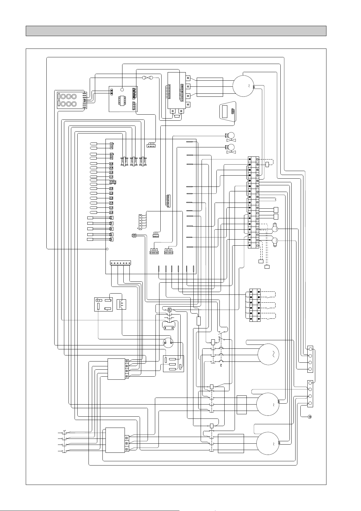
MODEL : 5ACV 210CR
ELECTRICAL WIRING DIAGRAM
W
FUSE
DC_OUT
JP_POWER
L1 FL2 FL1
IC090102
MAIN BOARD
JP14
ON/OFF
ALARM
CH
JK8
PWM1
JP_POWER1
JP1
BL
BL
RD BL BROR
JP232
EV1EV2
FAN-2-2
R_PHASE
U V
POWER1
IPM BOARD
N
P
0.47uF
C
R_PHASE
CP2
CP1
CC_H1
BOILER
PUMP
AU_H
JDC
BP_H
4WV2
4WV1
FAN-2-1
FAN-1-2
FAN-1-1
PHASE
BOARD
PE
TSR
PE
DC_IN
JP3
JK2 JK1 JK4 JK3 JK7 JP8 JP2 JP4 JP5 JP7 JP6 JP17 JP18 JP19 JP20 JP11 JP9
J-RST
N
DC+
DC1 +
DC2 +
JP_DC
DC DC1 DC2 -
CAPACITOR BOARD
TOR /
/
LP2 HP1 FLW HP2 LP1
POWER
TBPE-2
TBPL-2
TWE
TWL
TCS2
TCD2
TCS1
TOA
TBPL-1
TBPE-1
TOC2
TCD3
TCD1
TOC3
TOC4
TOC1
OR AISLANTE
BLACK
W
V
WHITE
COMP
U
RED
LCD
DISPLAY
PANEL
EV1EV2
GREEN/YELLOW
PART NO : 50 13 4 085020
AU_H
BP_H
4WV24WV1
CF1
18uF
FM1FM2
FAN-2-1 FAN-2-2 N FAN-1-2 FAN-1-1 4WV1 N 4WV2 BP_H N CC_H3 CC_H2 N CC_H1 BOIL N AU_H
TB3
CF2
18uF
FSC2
FSC1
AVEC INTERRUPTEUR ISOLANT / MIT SCHWINGUNGSISOLA
TOR SWITCH /
WITH ISOLA
OTERMICO / CON INTERRUPT
TORE MAGNET
CON SEZIONA
-
+
N
N
L2 L3
S T
L1
R
380~415V / 3PH / 50Hz
SWITCH
ISOLATOR
L
BR-1P
LA LB
G
N'
N
C'
C
(25A)
FTR2
B'
B
A
A'
G
N
C
C'
(50A)
FTR1
B
B'
A
A'
A2
A1
T3
T2
L1 L2 L3
T1
1
2
EST
1 2
PFC
R
-
S
T
+
BR-3P
97
98
A1
A2
96
95
PUMP
L1 L2 L3
T1 T2 T3
A1
A2
CP2
21
22
L1 L2 L3
T1 T2 T3
A1
A2
CP1
21
22
L1 L2 L3
T1 T2 T3
OR BL
BL
ON/OFF ON/OFFALARM ALARM
H/C H/C
RD BL BR
TB2
BLACK
V
WHITE
RED
BLACK
V
WHITE
RED
BLACK
V
WHITE
RED
HEAT/COOL ON/OFF ALARM
GREEN/YELLOW
W
PUMP
U
GREEN/YELLOW
W
U
GREEN/YELLOW
W
COMP 1 COMP 2
U
GROUND PLATE
TB4 TB5
iv
Page 7

INSTALLATION MANUAL
This manual provides the procedures of installation to ensure a safe and good standard of operation for the
chiller.
Special adjustments may be necessary to suit local requirements.
Before using the chiller, please read this instruction manual carefully and keep it for future reference.
AIR COOLED INVERTER CHILLER
MODEL
HEAT PUMP
English
R410A
5ACV210CR / A5ACV210CR
!!
! WARNING
!!
Installation and maintenance should be performed by qualified persons who are familiar with local code and
regulation, and experienced with this type of appliance.
Part No.: A08019028696
IM 5ACV210CR-0706 (0)-Acson
Page 8

INDEX
- Outline And Dimensions page i
- Unit Installation page ii
- Electrical Wiring Diagram page iv
- Transportation page 1
- Installation Location page 1
- Physical Data page 2
- Water Piping and Fitting page 2
- Electrical And Wiring page 3
- Electrical Data page 3
!!
! CAUTION
!!
- Recommended Fuse And Calbe Sizes page 3
- Refrigerant Circuit page 4
- Special Precautions When Dealing With R410A Unit
- Refrigerant Circuit Diagrams page 5
- Control Operation Guide page 6
- LCD Panel Installation page 6
- Maintenance page 7
- Troubleshooting page 7
Please take note of the following important points when installing.
Do not install the unit where leakage of flammable gas may occur.
If gas leaks and accumulates around the unit, it may cause fire ignition.
Do not over charge the unit.
This unit is factory pre-charged. Overcharge will cause over-current or damage to the compressor.
page 4
Sharp edges and aluminium fin coil surface are potential location which may cause injury hazards
Avoid from being in contact with these locations.
TRANSPORTATION
The unit should be lifted using a crane. Ensure that the hanger belts are not touching
panel and the coil, top front panel (use protective panel) as shown in Figure 1.
The bolt of the base and channel support can be removed after putting the unit on the
fixed location.
Protective Panel
Figure 1
Hanging Belt
Hanger
08 02 4 087984
INSTALLATION LOCATION
Installation work should be done by the authorized dealer or qualified contractor.
Make sure there is sufficient airflow around the unit.
Vibration isolator should be provided to prevent vibration and noise from the unit.
There should be sufficient space allocated fro servicing and maintenance.
1-1
Page 9

PHYSICAL DATA
Table A-1 : R410A - Heat Pump
Model 5ACV210CR
Nominal cooling capacity kW 58.56
Nominal heating capacity kW 61.49
Operating Weight kg 682.0
Refrigerant charge R410A kg 9.5 / 8.5
Compressor 2 Scroll + 1 Inverter Compressor
Control system LCD Electronic Control
Refrigerant - water heat exchanger Brazed Plate Heat Exchanger
Water connections (BSP) inches 1 1/2
Maximum water pressure kPa 1000
Hydr onic circuit
Pump Horizontal Multistage End-Suction
Available pressure (Cooling/Heating) kPa 258.5 / 244.0
Water inlet connection (BSPT) inches 1 1/2
Water outlet connection (BSPT) inches 1 1/2
Drain tap coupling (BSPT) inches 1/2
Closed expansion tank water volume litre 8
Refrigerant - air heat exchanger
Tube diameter mm 9.52
No. of rows 2
Tubes/row 62
Fin spacing mm
Fan
Diameter/Number of O/D fan mm 32 x 2
No. of blades 6
Air flow (high speed) m
Fan speed (high speed) r/min 550
3
/hr 11890
0.6299
English
Note: For cooling nominal values are based on 12°C / 7°C entering / leaving evaporator water temperature, 35°C air ambient
temperature.
Note: For heating nominal values are based on 40°C / 45°C entering / leaving evaporator water temperature, 7°C DB / 6°C
WB air ambient temperature.
WATER PIPING AND FITTING
All water pipe must be insulated to prevent capacity losses and condensation.
Install a 40-60 mesh strainer to ensure water quality is good.
Water pipe recommended are black steel pipe and copper pipe.
During installation, the piping of the unit should be clamp before rotating the installation pipe to reduce the moment induce
on the unit piping.
Users are recommended to install the pipe and accessories as shown in Figure 2.
An air vent must be installed at the highest position, while a drainage plug at the lowest position of the water circuit. Open
the air vent to release any air trap in the water circuit.
Run the clean water through the water inlet and operate the pump to drain out the dirty water. Clean the strainer after
running the pump for 30 minutes.
Fill up the water circuit after connecting all the pipes and equipment. Check water leakages at all connections and joints.
Do not start the unit when the system is leaking. To optimize the capacity of the system. ensure that the system is free of air
bubbles. The air trapped in the system would make the system unbalanced.
1-2
Page 10

AIRVENT (INSTALL
HIGHEST POSITION)
PRESSURE GAUGE
GATE
VALVE
THERMOMETER
FLEXIBLE
THERMOMETER
FLEXIBLE
GATE
VALVE
GATE
BALANCING
VALVE
VALVE
GATE
VALVE
!!
! CAUTION
!!
BALANCING
VALVE
STRAINER
CHECK
VALVE
GATE
VALVE
PRESSURE
DIFFERENTIAL
VALVE
(LOWER POSITION
FOR DRAINAGE)
MAKE UP
VALVE
FAN COIL UNIT/AIR HANDLING UNIT
GATE VALVE
Do not allow water remain in the water pipes if the unit is not operating for a long period.
Water must be drained out if the unit is not running during winter. failing to do so would cause the pipe to crack.
Do not drink the chilled water in the unit.
ELECTRICAL AND WIRING
Refer to the wiring diagram provided on the unit when making electrical wiring.
Do not ground any electrical equipment to the water piping.
Figure 2
ELECTRICAL DATA
Table B-1 : R410A - Heat Pump
Model 5ACV210CR
Power supply V-ph-Hz 400 / 3 / 50
Voltage range V 380-415
Nominal Power Input (Cooling/Heating) kW 23.2 / 22.9
Nominal Current Input (Cooling/Heating) A 38.5 / 38.1
System 1(inv)* System 1 System 2
Compressor Maximum Continuous Current A 21.0 17.0 29.0
Compressor Full Load Current (FLA) A 16.4 10.7 22.2
Compressor Locked Rotor Current (LRA) A - 90 118
Pump Power Input (Cooling/Heating) W 1175 / 1294
* Readings taken at rated compressor frequency. The Power Input and Current differ depending on the combination of
outdoor temperature and entering water temperature. For further details, please refer to Technical Manual.
RECOMMENDED FUSE AND CALBE SIZES
Heat Pump
Model 5ACV 210 CR
Voltage Range ** 380 - 415V /3Ph /50Hz + N +
Recommended Fuse * A 100
Power Supply Cable Size * mm
Number of Conductor 5
Interconnection Cable Size mm
2
2
10
1.5
IMPORTANT : * The figures shown in the table are for information purpose only. They should be checked and selected to
comply with the local/national codes of regulations. This is also subject to the type of installation and
conductors used.
** The appropriate voltage range should be checked with label data on the unit.
1-3
Page 11

!!
! CAUTION
!!
• All field wiring must be installed in accordance with the national wiring regulation.
• All the terminals and connections must be tightened. Improper connection and fastenings could cause electric shock,
short circuit and fire.
• Ensure that the rated voltage of the unit corresponds to that of the name plate before commencing wiring work
according to the wiring diagram.
• The unit must be GROUNDED to prevent possible hazards due to insulation failure.
• All electrical wiring must not touch the refrigerant piping, compressor, pump, fan motor or any moving parts of
the fan motors.
• Do not operate the chiller with wet hands. It would result in electric shock.
• Do not use fuse of different amperage than stated. Using wire etc. to replace a fuse could cause equipment damage
or fire.
Electrical Wiring Diagram (please refer to Appendix 3).
REFRIGERANT CIRCUIT
• All mini chillers units are pre-charged with R410A refrigerant.
SPECIAL PRECAUTIONS WHEN DEALING WITH R410A UNIT
• R410A is a near azeotrope refrigerant blend of hydro fluorocarbon (HFC) which is environmental friendly. It has Zero
Ozone Depletion Potential (ODP=0) and this conforms to Montreal Protocol regulations. It has no flame propagation and
a low toxic refrigerant (rated as A1 by ARI). R410A is a mixture of R32 (50%) and R125 (50%).
• POE oil is used as lubricant for R410A compressor, which is different from the mineral oil used for R22 compressor.
During installation or servicing, extra precaution must be taken not to expose the R410A system too long to moist air.
Residual POE oil in the piping and components can absorb moisture from the air.
• Refrigerant R410A is more easily affected by dust of moisture compared with R22, make sure to temporarily cover the
ends of the tubing prior to installation.
• No additional charge of compressor oil only is permitted.
• No refrigerant other than R410A is permitted.
• Tools designed specifically for R410A only.
i) Manifold gauge and charging hose
ii) Gas leak detector
iii) Refrigerant cylinder/charging cylinder
iv) Vacuum pump c/w adaptor
v) Flare tools
vi) Refrigerant recovery machine
English
!!
! CAUTION
!!
• R410A must be charged as liquid. Usually R410A cylinder is equipped with a dip-pipe for liquid withdrawal.
If there is no dip-pipe, the cylinder should be inverted so as to withdraw liquid R410A from the valve.
• Do not top-up when servicing leak, as this will reduce the unit performance. Vacuum the unit thoroughly and then
charge the unit with fresh R410A according to the amount recommended in the specification.
• Do not touch the compressor or refrigerant piping when the chiller is running. If necessary wear protective gloves.
1-4
Page 12

5ACV 210CR
Refrigerant Circuit Diagram
TWIN
TUBE JOINT
OIL
SEPARATOR
VARIABLE SPEED
COMPRESSOR
OIL
RETURN
TUBE
TWIN
TUBE JOINT
FIN TUBE
HEAT EXCHANGER
(SYSTEM 1)
4-WAY VALVE
OIL
SEPARATOR
COMPRESSOR
SUCTION
ACCUMULATOR
EXV
LIQUID
RECEIVER
WATER
FILTER
DRIER
CHECK
VALVE
OUT
EXV
LIQUID
RECEIVER
WATER
IN
FILTER
DRIER
CHECK
VALVE
HEAT EXCHANGER
4-WAY VALVE
SUCTION
ACCUMULATOR
FIN TUBE
(SYSTEM 2)
COMPRESSOR
1-5
Page 13

CONTROL OPERATION GUIDE
The unit is equipped with a microprocessor controller board. The microprocessor controller is provided to give temperature
control for the system by accurately measuring and controlling the water entering and water leaving temperature. The temperature setting in the unit is preset in the factory. It is not recommended to change the setting unless necessary. A wired
controller handset is connected to the microprocessor board. Every parameter setting and reading can be observed from the
LCD of the handset.
JP14
JP7
JP10
JP6
JP5 JP4 JP3
SW1
JP-Y
JDC
CC-H1
BOILER
4WV1
SW2
4WV2
BP-H
AU-H
JK3 JK7
MAIN BOARD
PUMP
JK4
JK1 JK2
FAN2
FAN1
JP9
JP8 JP2
JP11
JP13
R-PHASE
1. Handset location
The handset is located on a metal bracket behind the right door panel.
2. LED Display (microprocessor board)
The keypad LED will light up when the unit is powered up.
The LCD will light up when the unit is turned on.
3. LCD display (controller handset)
During normal operations, the LCD can display the entering water temperature, the leaving water temperature, the entering water setpoint temperature, compressor on or off status and outdoor air temperature. When malfunctioning occurred,
the LCD would blink. The display would show the faulty parameter and the date and time of the occurrence.
4. Controller functioning specification
There is a 3 minute delay for the compressor and fan motor to restart (default setting).
During defrosting, fan motor is not running.
English
!!
! CAUTION
!!
• Use the controller handset to switch on / off the unit. Do not plug off the main power supply directly, it would cause
the unit to breakdown. In case of emergency switch off the isolator switch located on the front panel of the unit.
• Do not change the settings of the safety devices.
LCD PANEL INSTALLATION
• The unit comes with a LCD panel installed. To change the position or re-install the LCD panel, follow the installation
guide below.
When fastening the LCD panel to the bracket,
Step 1 Step 2
When removing the LCD panel from the bracket,
Step 1 Step 2
Hook the LCD panel
from the top first
Push to fasten the LCD
panel to the bracket
Remove the
LCD panel
Remove the LCD panel
from the bottom part first
with help of a screw driver
1-6
Page 14

1. A 3V DC battery is supplied with the LCD. It is used to ensure that the LCD displays real time once the timer is set.
2. The LCD is wired to the main board via CN8 connection. (This is factory installed)
If the wiring between the LCD and PCB must be longer, an alternative is used. Use a 4-core wire of the desired length and
connect this wire between the terminal block CN2 on the LCD to the terminal block CN5 on the PCB. Ensure that the
correct wire terminals are connected.
3. Networking between chillers can be carried out. Connect the wire as shown
JP13
Factory installed
LCD Panel
CN8
CN2
GND
12V
B
A
Alternative wiring between LCD panel and PCB
For networking only
Main Board unit 00
CN5
A
B
A
B
12V
GND
GND
12V
PCB unit 01
MAINTENANCE
• Maintenance service of the mini chiller must be carried out by qualified persons.
• The unit is easily accessible for servicing and maintenance by accessing the front panel of the unit (for electrical compo-
nents) and the panel door (for refrigerant and water circuit).
• For consistent performance it is recommended that a routine maintenance of cleaning the coil surfaces to conducted
because of dusty surroundings.
• It is also recommended that regular checks on the water strainer to be conducted. Change the water strainer if it is dirty or
choked.
!!
! CAUTION
!!
• Do not attempt to do any service or maintenance when the unit is operating.
• Do not spray any chemical agents or flammable agents to the unit. It could cause fire or explosion.
TROUBLESHOOTING
When any malfunction is occurred, immediately switch off the power supply to the unit, and contact the local dealer, if
necessary. Some simple troubleshooting tips are given below :
SYMPTOMS POSSIBLE CAUSES REMEDIAL ACTION
1. Compressor does
not start.
2. Fan does not work.
3. Unit does work,
but insufficient
cooling.
4. Flow Switch Error
• No power supply.
• Fuses blown or automatic circuit breakdown open.
• Defective contactor or coil.
• Unit is stopped because safety device has
tripped.
• Loose wires.
• Compressor faulty.
• No power supply.
• Fan motor faulty.
• Thermostat setting too high.
• Condenser coil dirty.
• Obstacle blocking air inlet or outlet of the
unit.
• Insufficient refrigerant in the system.
• Improper water flow rate.
• Water in the system is contaminated.
• No water in the system.
• Low water level in the system.
• Check power supply.
• Look for short circuit or grounded wires in
motor windings. Replace fuses and reset
circuit breakers when the fault has been
corrected. Check tightness and soundness of
all electrical connections.
• Repair or replace.
• Determine the type of safety shut down and
correct the default before the unit is restarted.
• Check wire connections and tighten terminal
screws.
• Contact local dealer.
• Check power supply.
• Contact local dealer.
• Reset thermostat.
• Contact local dealer.
• Remove the obstacle.
• Contact local dealer.
• Contact local dealer.
• Contact local dealer.
• Check water supply.
• Check water supply.
!!
! CAUTION
!!
• Troubleshooting must be performed by qualified personnel.
1-7
Page 15

Page 16

• In the event that there is any conflict in the interpretation of this manual and any translation of the same in any language,
the English version of this manual shall prevail.
• The manufacturer reserves the right to revise any of the specification and design contain herein at any time without prior
notification.
• En cas de désaccord sur l’interprétation de ce manuel ou une de ses traductions, la version anglaise fera autorité.
• Le fabriquant se réserve le droit de modifier à tout moment et sans préavis la conception et les caractéristiques techniques
des appareils présentés dans ce manuel.
• Im Falle einer widersprüchlichen Auslegung der vorliegenden Anleitung bzw. einer ihrer Übersetzungen gilt die Ausführung
in Englisch.
• Änderungen von Design und technischen Merkmalen der in dieser Anleitung beschriebenen Geräte bleiben dem Hersteller
jederzeit vorbehalten.
• Nel caso ci fossero conflitti nell’interpretazione di questo manuale o delle sue stesse traduzioni in altre lingue, la versione
in lingua inglese prevale.
• Il fabbricante mantiene il diritto di cambiare qualsiasi specificazione e disegno contenuti qui senza precedente notifica.
• En caso de conflicto en la interpretación de este manual, y en su traducción a cualquier idioma, prevalecerá la versión
inglesa.
• El fabricante se reserva el derecho a modificar cualquiera de las especificaciones y diseños contenidos en el presente
manual en cualquier momento y sin notificación previa.
• В случае противоречия перевода данного руководства с другими переводами одного и того же текста,
английский вариант рассматривается как приоритетный.
• Завод-изготовитель оставляет за собой право изменять характеристики и конструкцию в любое время
без предварительного уведомления.
OYL MANUFACTURING COMPANY SDN. BHD.
JALAN PENGAPIT 15/19, P.O. BOX 7072, 40702 SHAH ALAM, SELANGOR DARUL EHSAN, MALAYSIA.
 Loading...