

ACS Motion Control MC4U-19-Piano-enc, MC4U-9-Piano-enc, MC4U-22-Piano-enc, MC4U-11-Piano-enc, MC4U-13-Piano-AX7 Hardware Manual
Page 1

MP4U
Control Module
Hardware Guide
December 2017
Document Revision: 2.50.D
Page 2

MC4UHardwareGuide
MC4U
ReleaseDate: December2017
Copyright
© ACSMotionControlLtd.2017.Allrightsreserved.
Changesareperiodically madetotheinformationinthisdocument.Changesarepublished asreleasenotesandlater
incorporatedintorevisionsof thisdocument.
Nopart of thisdocumentmay bereproducedinanyformwithoutpriorwritten permissionfromACSMotionControl.
Trademarks
ACSMotionControl, SPiiPlus,PEG, MARK, ServoBoost,NetworkBoost and NanoPWMare trademarksof ACS MotionControlLtd.
Windows andVisualBasicare trademarksof MicrosoftCorporation.
EtherCAT is registeredtrademark and patentedtechnology,licensedbyBeckhoff AutomationGmbH,Germany.
Anyother companies and product namesmentioned hereinmaybe thetrademarks of theirrespectiveowners.
Patents
ACS MotionControlLtd.NanoPWMproducts areprotectedunderthefollowingpatents:
IsraelPatent No.235022
US Patent ApplicationNo. 14/532,023
EuropePatentapplication No.15187586.1
JapanPatentApplication No.: 2015-193179
ChinesePatentApplication No.:201510639732.X
Taiwan(R.O.C.)PatentApplication No.104132118
KoreanPatent ApplicationNo.10-2015-0137612
www.acsmotioncontrol.com
support@acsmotioncontrol.com
sales@acsmotioncontrol.com
Notice
Theinformationinthisdocument isdeemedto be correctat thetime ofpublishing.ACSMotionControlreservestherightto
changespecifications withoutnotice.ACSMotionControlis not responsiblefor incidental,consequential,or special damagesof
anykindinconnectionwithusingthisdocument.
Version 2.50.D
2
Page 3

RevisionHistory
Date Revision Description
MC4UHardwareGuide
December
2017
July2017 2.40.D Removed SPiiPlusADKSuitesoftwarediscshipping withMC4U.
November
2016
August
2016
May2016
November
2015
June2015 2.29.01
2.50.D Reformatted
2.30.01.
D
2.30.D
2.29.20.
D
2.29.10.
D
Returned motherboardsectionsnot includedin Version2.30.D
Updated forSPiiPlusADK Suitev2.30.
Updated RelatedDocumentslist.
Addedminimumhardware revisionandSPiiPlusFirmware
versionrequirements.
Updated absoluteencoderbidirectionalschematicdiagram
Updated STOnote
Addednote concerningSTO certification.
Majordocument update:removalof unsupported modules,
informationrevised,documentrestructuredfor usability.
March
2015
2.29 Updated forVersion2.29features.
Version2.50.D
3
Page 4

ConventionsUsedinthisGuide
TextFormats
Format Description
Bold Namesof GUI objects orcommands.
BOLD+UPPERCASE ACSPL+variablesandcommandss
MC4UHardwareGuide
FlaggedText
Monospace + grey
background
Italic Namesof other documents.
Blue Web pages,ande-mailaddresses.
[ ] InGUIsindicatesoptional item(s)
| InGUIsindicateseither/or items
Note -includesadditional information orprogrammingtips.
Caution -describes aconditionthat mayresult indamageto equipment.
Warning -describes acondition thatmayresult inserious bodily injuryor death.
Model -highlightsaspecification, procedure, condition, orstatement that depends
on the product model.
Code example.
Version 2.50.D
Advanced -indicatesatopic for advanced users.
4
Page 5

MC4UHardwareGuide
RelatedDocuments
Documents listed inthe following table provide additionalinformationrelated to this document.
The most updated versionof the documents can be downloaded by authorized users from
www.acsmotioncontrol.com/downloads.
Document Description
Provides communication,configurationand
SPiiPlus Setup Guide
SPiiPlus Utilities User Guide
adjustment procedures for the MC4U Control
Module motion controller.
A guide for usingthe SPiiPlusUser ModeDriver
(UMD) for setting up communicationwith the
SPiiPlusmotion controller.
ACSPL+ Programmer’s Guide
SPiiPlus Command and Variable
Reference Guide
SPiiPlus CLibrary Programmer
Guide
SPiiPlus COMLibrary
Programmer Guide
SPiiPlus .NET Library
Programmer Guide
SPiiPlus MMI Application Studio
User Guide
Guide for usingthe ACSPL+high level
programminglanguage.
Provides complete details ofthe ACSPL+
programminglanguage command andvariable
set for programming SPiiPluscontrollers.
Provides C++andVisual Basic®libraries for host
PCapplications. Thisreference isspecifically
applicable for the MC4UControl Module motion
controller.
Provides COMMethods,Properties, and Events
for Communication with the MC4U Control
Module motion controller.
Provides .NET Methods,Properties,andEvents
for Communication with the MC4U Control
Module motion controller.
A complete guide for using the SPiiPlusMMI
Application Studio and associated monitoring
tools
SPiiPlusNT/DC Motion Controller
Hardware Guide
SPiiPlus PDMnt Product Guide
SPiiPlus SDMnt Product Guide
Version 2.50.D
Provides detailsfor the SPiiPlusNT-LT/HPand
SPiiPlusDC-LT/HPmotion controllers, one of
which isinstalled in the MC4UControl Module.
Technical descriptionof the SPiiPlusPDMnt
Network Interface.
Technical descriptionof the SPiiPlusSDMntStep
Motor DriveModule.
5
Page 6

Document Description
MC4UHardwareGuide
SPiiPlus UDMnt Product Guide
PEGand MARKOperations
Application Notes
Using Absolute Encoderswith
ACS Products AN3.00
HSSIExpansion Modules Guide
SPiiPlus ADK Suite v2.50
Release Notes
Technical descriptionof the SPiiPlusUDMnt
UniversalDrive Module.
Provides detailsonusing the PEG commandsin
SPiiPlussystems.
Addressesthe physicalconnections,
configurationandoperationof absolute
encoderswith ACSMotionControl networking
products.
High-SpeedSynchronousSerialInterface(HSSI)
for expanded I/O, distributed axes, and
nonstandard devices.
Describesnewfeatures andchanges thatwere
introduced sincethe last SPiiPlusNTSuite
version 2.40 release.
Version 2.50.D
6
Page 7

MC4UHardwareGuide
TableofContents
1. Introduction 24
1.1 Document Scope 24
1.2 Product Overview 24
1.2.1 MC4U-9-Piano-enc 24
1.2.2 MC4U-11-Piano-enc 25
1.2.3 MC4U-13-Piano-AX7 26
1.2.4 MC4U-19-Piano-enc 27
1.2.5 MC4U-22-Piano-enc 28
1.3 Software Package 29
2. MC4USpecifications 30
2.1 MC4U PhysicalSpecifications 31
2.1.1 MC4UDimensions 31
2.1.1.1 MC4U-9-Piano-enc Dimensions 31
2.1.1.2 MC4U-11-Piano-encDimensions 32
2.1.1.3 MC4U-13-Piano-AX7 Dimensions 33
2.1.1.4 MC4U-19-Piano-enc Dimensions 34
2.1.1.5 MC4U-22-Piano-enc Dimensions 35
2.1.2 MC4U Weight 36
2.1.3 MC4U PowerDissipation 36
2.1.4 MC4U EnvironmentalParameters 37
2.1.5 MC4U CoolingVents 38
2.2SPiiPlusNT/DC MotionControllers 38
2.2.1 SPiiPlusNT/DC MotionControllersFeatures 40
2.2.2SPiiPlusNT/DC Indicators 46
2.3PSM3UPower Supplies 48
2.3.1 PSM3U Specifications 54
2.3.1.1 PSM3U-48V-XXkW Power Supply 54
2.3.1.2 PSM3U-320V-8kW Power Supply 56
2.4 Motor Drives 64
Version 2.50.D
2.3.1.3 PSM3U-320V-20KWPowerSupply 62
2.4.1 PWM Drives 64
2.4.1.1 DDM3U-X-60V-4A Low-Power Motor Drive 65
2.4.1.1.1 DDM3U-X-60V-4A Specifications 66
7
Page 8

MC4UHardwareGuide
2.4.1.2 DDM3U-1-320V-XX-SRMotor Drive 69
2.4.1.2.1 DDM3U-1-320V-XX-SRSpecifications 70
2.4.1.2.2 DDM3U-1-320V-XX-SRPWMPower Bridge Specification 72
2.4.1.2.3 DDM3U-1-320V-XX-SRDrive Protection Circuits 73
2.4.1.3 DDM3U-2-320V-XA High-PowerMotor Drive 75
2.4.1.3.1 DDM3U-2-320V-XASpecifications 75
2.4.1.3.2 DDM3U-2-320V-XA PWM PowerBridge Specification 81
2.4.1.4 DDM3U-4-320V-XAMotor Drive 86
2.4.1.4.1 DDM3U-4-320V-XA Power SupplyInput Specification 88
2.4.1.4.2 DDM3U-4-320V-XAControl Supply Input Specification 89
2.4.1.4.3 DDM3U-4-320V-XA PWMPowerBridge Specification 90
2.4.1.4.4 DDM3U-4-320V-XADrive Protection Circuits 91
2.4.2 LDM3USingle AxisLinear Drive 92
2.4.2.1 LDM3USpecifications 94
2.5MC4UMotherboards 96
2.5.1 MB4U-ZZW-AX7 96
2.5.1.1 MB4U-ZZW-AX7 Functionality 96
2.5.1.2 J1 -24VLogic & I/OSupply Connector 96
2.5.1.3 J2 -EtherCAT® OUTConnector 97
2.5.1.4 J3 -Ether Cat INConnector 98
2.5.1.5 J4 -Encoder Connector 98
2.5.1.6 J5 -EncoderConnector 102
2.5.1.7 J6 -DriveSupply Connector 105
2.5.1.8 J7-J10 -Motor Connectors 106
2.5.1.9 J11-J14-Motor Connectors 107
2.5.2MB5U-CONT-PS 108
2.5.2.1 MB5U-CONT-PSFunctionality 108
2.5.2.2Encoder andHallConnectors 109
2.5.2.3J7-Squared SIN-COS Connector 111
2.5.2.4J8-Digital and Analog I/OConnector 112
Version 2.50.D
2.5.2.5J9 -Regeneration Connector 114
2.5.2.6J21 -Fast I/O(PEGand Mark) Connector 115
2.5.2.7 J22-Motor LimitsConnector 117
2.5.2.8J4,J5,andJ6-HSSIConnectors 118
2.5.2.9J2andJ3-Ethernet Connectors 119
8
Page 9

MC4UHardwareGuide
2.5.2.10J19 and J20RS-232 CommunicationConnectors 120
2.5.2.11 J14 -Drive Supply Voltage Connector 120
2.5.2.12J1 -24V LogicSupply Connector 121
2.5.2.13MB5U-CONT-PSJumpers 121
2.5.3MB5U-CONT-PS2 124
2.5.3.1 MB5U-CONT-PS2Functionality 124
2.5.3.2J1 -24V Logic Supply Connector 125
2.5.3.3Encoder andHallConnectors 125
2.5.3.4J7 -Squared SIN-COS Connector 127
2.5.3.5J8 -Digital and Analog I/OConnector 128
2.5.3.6J14, J114 -Drive SupplyVoltage Connector 131
2.5.3.7 J21 -Fast I/O(PEGand Mark) Connector 132
2.5.3.8J22-MotorLimitsConnector 134
2.5.3.9J4,J5,andJ6-HSSIConnectors 135
2.5.3.10J2andJ3-Ethernet Connectors 136
2.5.3.11 J19 andJ20RS-232 CommunicationConnectors 137
2.5.3.12J9, J109- Regeneration Connector 137
2.5.3.13J145 -60V Drive SupplyConnector 138
2.5.3.14 MB5U-CONT-PS2Jumpers 138
2.5.4MB5U-Lin 140
2.5.4.1 MB5U-LinMFunctionality 141
2.5.4.2J130(D0)-DriveMotor 141
2.5.4.3MB5U-LinJumpers 142
2.5.5MB5U-LinM 143
2.5.5.1 MB5U-LinMFunctionality 143
2.5.5.2J130(D0) -Drive Motor 143
2.5.5.3MB5U-LinM Jumpers 144
2.5.6MB5U-YYYY 145
2.5.6.1 MB5U-YYYY Functionality 145
2.5.6.2Encoder andHallConnectors 146
Version 2.50.D
2.5.6.3J7 -Squared SIN-COSConnector 148
2.5.6.4 J8 -DigitalandAnalogI/O Connector 149
2.5.6.5J9-Regeneration Connector 151
2.5.6.6J21 -Fast I/O(PEG& Mark)Connector 152
2.5.6.7 J22-Motor LimitsConnector 154
9
Page 10

MC4UHardwareGuide
2.5.6.8J4, J5, andJ6-HSSI Connectors 155
2.5.6.9J2andJ3-Ethernet Connectors 156
2.5.6.10J19 and J20RS-232 CommunicationConnectors 157
2.5.6.11 J14-Drive Supply VoltageConnector 157
2.5.6.12 J1 -24VLogic Supply Connector 158
2.5.6.13 J40-External DriveControl Signals 158
2.5.6.14 J152_$ - Motor DriveOutput Connectors 160
2.5.6.15MB5U-YYYY Jumper Configuration 161
2.5.7 MB5U-Z 164
2.5.7.1 MB5U-Z Functionality 165
2.5.7.2 Encoder and Hall Connectors 166
2.5.7.3 J10 -DigitalandAnalogI/O Connector 167
2.5.7.4 J20-Safety & Fast I/O InputsConnector 170
2.5.7.5J3,J4-Drive Motor Connectors 171
2.5.7.6 J6 and J7 -Ethernet Connectors 172
2.5.7.7 J8 -HSSIConnector 173
2.5.7.8 J19 -RS-232 CommunicationConnector 174
2.5.7.9 J13 -ExternalDrive Control Signals 174
2.5.7.10 J11 -External Regeneration 176
2.5.7.11 J12 -Drive SupplyConnector 176
2.5.7.12 J5 -24V LogicSupply Connector 177
2.5.7.13 MB5U-Z Jumper Configuration 177
2.5.8MB5U-ZV 179
2.5.8.1 MB5U-ZVFunctionality 180
2.5.8.2Encoder andHallConnectors 181
2.5.8.3J10-Digital and Analog I/OConnector 182
2.5.8.4J20-Safety &FastI/OInputs Connector 185
2.5.8.5J1, J3, J21,J22-DriveMotor Connectors 187
2.5.8.6J2andJ4-Drive Motor Connectors 187
2.5.8.7 J8, J9 andJ30-HSSI Connectors 189
Version 2.50.D
2.5.8.8J6andJ7 -Ethernet Connectors 189
2.5.8.9J19 -RS-232CommunicationConnector 190
2.5.8.10J23-Z&CSafety Connector 190
2.5.8.11 J11-External Regeneration 191
2.5.8.12 J12 -DriveSupply Input 191
10
Page 11

MC4UHardwareGuide
2.5.8.13 J5-24VLogicSupply 192
2.5.8.14 MB5U-ZVJumpers 192
2.5.9MB5U-ZZ 195
2.5.9.1 MB5U-ZZFunctionality 196
2.5.9.2Encoder andHallConnectors 196
2.5.9.3J10-Digital and Analog I/OConnector 198
2.5.9.4 J20-Safety &FastI/OInputs Connector 200
2.5.9.5J1, J2, J3,J4-DriveMotor Connectors 202
2.5.9.6J6and J7 -Ethernet Connectors 203
2.5.9.7 J8 and J9-HSSIConnectors 204
2.5.9.8J19 -RS-232CommunicationConnector 204
2.5.9.9J11 -ExternalRegeneration 205
2.5.9.10J12 -DriveSupply Connector 205
2.5.9.11 J5 -24V LogicSupply Connector 206
2.5.9.12 MB5U-ZZJumpers 206
2.5.10MB5U-ZZW 208
2.5.10.1 MB5U-ZZWFunctionality 209
2.5.10.2Encoder andHallConnectors 210
2.5.10.3J7 -Squared SIN-COS Connector 212
2.5.10.4 J8 -DigitalandAnalogI/O Connector 213
2.5.10.5J9-Regeneration Connector 215
2.5.10.6J21 -Fast I/O(PEG& Mark)Connector 216
2.5.10.7 J22 -Motor LimitsConnector 218
2.5.10.8J4, J5, andJ6-HSSIConnectors 219
2.5.10.9J2andJ3-Ethernet Connectors 220
2.5.10.10 J19 andJ20RS-232CommunicationConnectors 221
2.5.10.11 J14-Drive Supply VoltageConnector 221
2.5.10.12 J1 -24VLogic Supply Connector 222
2.5.10.13 J40 -ExternalDriveControl Signals 222
2.5.10.14 J152_$ - Motor DriveOutput 223
Version 2.50.D
2.5.10.15 J125 -ExternalDC Drive Supply Input 225
2.5.10.16 J121 -J124 Low-Power Motor Connectors 226
2.5.10.17 MB5U-ZZW Jumpers 227
2.5.11 MB5U-ZZZ 230
2.5.11.1 MB5U-ZZZFunctionality 230
11
Page 12

MC4UHardwareGuide
2.5.11.2 Encoder and HallConnectors 231
2.5.11.3 J7 -Squared SIN-COS Connector 233
2.5.11.4 J8-Digital and Analog I/OConnector 234
2.5.11.5 J9 -Regeneration Connector 236
2.5.11.6 J21 -FastI/O(PEG& Mark) Connector 237
2.5.11.7 J22-Motor Limits Connector 239
2.5.11.8 J4, J5,andJ6-HSSIConnectors 241
2.5.11.9 J2 andJ3-Ethernet Connectors 241
2.5.11.10 J19andJ20RS-232CommunicationConnectors 242
2.5.11.11 J14 -Drive Supply VoltageConnector 243
2.5.11.12 J1 -24V LogicSupply Connector 243
2.5.11.13 J40-ExternalDrive Control Signals 244
2.5.11.14 J152_$ -Motor DriveOutput 245
2.5.11.15 MB5U-ZZZ Jumpers 246
2.5.12 MB5U-2-45 249
2.5.12.1 J152-0,J152-1-Servo MotorDrive 249
2.5.12.2B5U-2-45Jumpers 250
2.5.13 MB5U-2-20 250
2.5.13.1 J152 -ServoMotor Drive 251
2.5.13.2MB5U-2-20 Jumpers 252
2.5.14 MB5U-4-XX 253
2.5.14.1 MB5U-4-XXFunctionality 254
2.5.14.2 ServoMotor Drive Connectors 254
2.5.14.3 MB5U-4-XXJumpers 256
2.6 MC4U Accessories 256
2.6.1 MC4U-MF-560V MotorFilter 257
2.6.1.1 Motor Filter Operational Specifications 258
2.6.1.2 J1 -Drive Connector 259
2.6.1.3 J2 -Motor Connector 259
2.6.1.4 MotorFilter PhysicalSpecifications 259
3. SafetyandEMCGuidelines 262
3.1 Certification 262
3.2General Safety Guidelines 262
Version 2.50.D
2.6.1.5 Connecting the Motor Filter 261
2.6.2MC4U-REGEN-600 Regeneration Module 261
12
Page 13

MC4UHardwareGuide
3.2.1 MC4U Handling& Maintenance 263
3.2.2Safe Torque Off (STO) 263
3.2.2.1 STO Module Connector Type andPinout 265
3.2.3EmergencyStop Device 265
3.2.4 FailSafe LogicRecommendation 265
3.2.5InitialLogicState of Outputs 265
3.2.6Electrical Separation 266
3.2.7 Over-Travel Protection 266
3.2.8ThermalDetection 266
3.2.9Power Supply and Motor Cable Ground 266
3.3General Wiring and EMCGuidelines 266
3.3.1 ExternalACLineFilters 266
3.3.2ACS Motor Filters 267
3.3.3Routing SignalandPowerCables 267
3.3.4 Cable Length 267
3.3.5Grounding 268
3.3.5.1 SafetyGrounding 268
3.3.5.2High Frequency Grounding 268
4. Circuit Protection 269
4.1 InternalIntegratedDrive Protection Circuits 269
4.1.1 Soft Start Circuit 269
4.1.2 MotorRegenerationCircuit 269
4.1.3 PSM3U Low-Power PS 269
4.1.4 PSM3UHigh-PowerPS 270
4.1.5 DDM3U Low-Power Motor Drive 270
4.1.6 DDM3UHigh-Power Motor Drive 271
4.2 Fuses 271
4.2.1 PSM3U Power Supply Fuses 271
4.2.1.1 PSM3ULow-Power AC InputPower Fuses 271
4.3 Fault Handling 273
Version 2.50.D
4.2.1.2 PSM3U Low-Power 24VdcLogicSupply Input Fuses 272
4.2.1.3 PSM3U High-Power ACInputPower Fuses 272
4.2.2 DDM3U Motor DrivesFuses 272
4.2.2.1 DDM3U-X-60V-4A Low-Power Motor DriveFuses 272
4.2.2.2DDM3U-2-320V-YY High-PowerMotor Drive Fuses 272
13
Page 14

MC4UHardwareGuide
5. MC4UConnectivity 276
5.1 MC4U I/ONaming Conventions 276
5.2Incremental Digital Encoder Interface 277
5.3Sin-CosEncoder Input 277
5.4 AbsoluteEncoder Interface 278
5.5I/O Interface 280
5.6HallInterface 281
5.7 Motor Temperature Input 282
5.8EmergencyStop Input 283
5.9MARK1 Registration DigitalInput 283
5.10PEGPulseOutput 284
5.11 JoystickInput Interface 284
6. InstallationandMaintenance 286
6.1 Installing the MC4U 286
6.1.1 Panel-Mountingthe MC4U 286
6.1.2 Rack-Mounting the MC4U-19-Piano-enc andMC4U-22-Piano-enc 287
6.2 Maintenance 288
6.2.1 Replacing MC4UComponents 288
6.2.2Replacing CoolingVents 288
Version 2.50.D
14
Page 15

MC4UHardwareGuide
ListOfFigures
Figure 1-1. MC4U-9-Piano-enc 25
Figure 1-2. MC4U-11-Piano-enc 26
Figure 1-3. MC4U-13-Piano-AX7 27
Figure 1-4. MC4U-19-Piano-enc 28
Figure 1-5. MC4U-22-Piano-enc 29
Figure 2-1. MC4U Components 30
Figure 2-2.MC4U-9-Piano-enc Dimensions 32
Figure 2-3.MC4U-11-Piano-enc Dimensions 33
Figure 2-4.MC4U-13-Piano-AX7 Dimensions 34
Figure 2-5.MC4U-19-Piano-enc Dimensions 35
Figure 2-6.MC4U-22-Piano-encDimensions 36
Figure 2-7. SPiiPlusNT GeneralView 39
Figure 2-8.SPiiPlusNT/DC Indicators(SPiiPlusNTshown) 47
Figure 2-9.DDM3U-4-320V-XAMotor Drive 87
Figure 2-10.LDM3U Single AxisLinearAmplifier 92
Figure 2-11. MB4U-ZZW-AX7 Connectors 96
Figure 2-12. MB5U-CONT-PS Connectors 108
Figure 2-13.MB5U-CONT-PS Jumpers andPinNumbers 122
Figure 2-14. MB5U-CONT-PS2 Connectors 124
Figure 2-15.MB5U-CON-PS2 Motherboard Jumpers andPinNumbers 139
Figure 2-16. MB5U-Lin 141
Figure 2-17. MB5U-LinM 143
Figure 2-18. MB5U-YYYY Connectors 145
Figure 2-19. Source-Type Drive Enable Output (D Axis) 160
Figure 2-20.MB5U-YYYY Motor Drive Connections 161
Figure 2-21. MB5U-YYYY Jumpers 162
Figure 2-22.MB5U-ZConnectors 165
Figure 2-23.MB5U-ZMotor Drive Connections 172
Figure 2-24.Source -Type DriveEnable Output (B Axis) 176
Figure 2-25.MB5U-Z MotherboardJumpers andPinNumbers 178
Figure 2-26.MB5U-ZVConnectors 180
Figure 2-27.MB5U-ZVMotor Drive Connections 188
Figure 2-28.MB5U-ZVJumpers 193
Figure 2-29.MB5U-ZZConnectors 195
Version 2.50.D
15
Page 16

MC4UHardwareGuide
Figure 2-30.MB5U-ZZ Motor DriveConnections 203
Figure 2-31.MB5U-ZZJumpers and PinNumbers 207
Figure 2-32.MB5U-ZZW Connectors 209
Figure 2-33.MB5U-ZZW J152Motor Drive Connections 225
Figure 2-34.MB5U-ZZWJ121-J124Motor DriveConnections 227
Figure 2-35.MB5U-ZZW Motherboard Jumpersand Pin Numbers 228
Figure 2-36.MB5U-ZZZ Connectors 230
Figure 2-37.MB5U-ZZZMotor Drive Connections 246
Figure 2-38.MB5U-ZZZ Jumpers and Pin Numbers 247
Figure 2-39.MB5U-2-45 Connectors 249
Figure 2-40.MB5U-2-20 Connectors 251
Figure 2-41. MB5U-2-20 Motor DriveConnections 252
Figure 2-42.MB5U-4-XXConnectors 254
Figure 2-43.MB5U-4Motor DriveConnections 255
Figure 2-44. MC4U-MF-560V Motor Filter 258
Figure 2-45.Motor Filter ExternalDimensions 260
Figure 2-46.RegenerationModule 261
Figure 3-1. StandardsOrganization Marks 262
Figure 3-2.STO Wiring Scheme 264
Figure 3-3.STO Implementation 264
Figure 3-4.Cable Spacing 267
Figure 3-5.Shielded Cable 267
Figure 3-6.MC4UGrounding Post 268
Figure 5-1. Incremental DigitalEncoder Interface (X-axis) 277
Figure 5-2.Sin-CosEncoder Interface 278
Figure 5-3.Absolute Encoder HiperfaceSchematic Diagram 279
Figure 5-4.Absolute Encoder Schematic Diagram 279
Figure 5-5.Absolute Encoder BidirectionalSchematic Diagram 280
Figure 5-6.I/OInterfaceSchematic Diagram 281
Figure 5-7.HallInterface Schematic Diagram 282
Figure 5-8.Connection to Motor Temperature Input (X-axis) 283
Figure 5-9.Connection for Emergency Stop Input 283
Figure 5-10.Differential Connection for MARK1 Input (X-axis) 284
Figure 5-11. PEGPulse DigitalOutput Connection (X-axis) 284
Figure 5-12.Analog Inputswith 0-10V Configuration 285
Version 2.50.D
16
Page 17

MC4UHardwareGuide
Figure 5-13.A ±5V Differential Joystick through AIN 285
Figure 6-1. MC4U-9-Piano-enc and MC4U-11-Piano-encPanel-Mounting 286
Figure 6-2.MC4U-19-Piano-enc andMC4U-22-Piano-encPanel-Mounting 287
Figure 6-3.MC4U-19-Piano-enc andMC4U-22-Piano-encRackMount 287
Version 2.50.D
17
Page 18

MC4UHardwareGuide
ListofTables
Table 2-1.MC4U-9-Piano-enc Dimensions 31
Table 2-2. MC4U-11-Piano-encDimensions 33
Table 2-3. MC4U-13-Piano-AX7 Dimensions 33
Table 2-4.MC4U-19-Piano-enc Dimensions 34
Table 2-5. MC4U-22-Piano-encDimensions 35
Table 2-6.MC4U Power Dissipation @NominalLoad 37
Table 2-7.MC4UEnvironmental Specification 38
Table 2-8. CTIMEValuesfor MC4UntSPiiPlusNT-LT/HP/LD/NP(Rev. D and later) Controller 41
Table 2-9.SPiiPlusNT/DC-LT/HP/LD AdditionalFeatures 42
Table 2-10.SPiiPlusNT/DCIndicators 47
Table 2-11. PSM3U Power Supplies-General 49
Table 2-12.PSM3U-48V-XXkWLow-Power PSSpecifications 54
Table 2-13.PSM3U-320V-8kWHigh-PowerPS Specifications 57
Table 2-14.Maximum Input Power @Single Phase Input 85 -265Vac 59
Table 2-15.Maximum InputPower @Three PhaseInput 195-265Vac 59
Table 2-16.Maximum Input Current @Single Phase Input 85- 265Vac 60
Table 2-17.Maximum Input Current @ThreePhaseInput 195-265Vac 60
Table 2-18.Output Voltage @SinglePhaseInput 85- 130Vac 60
Table 2-19.Output Voltage @SinglePhaseInput 195-265Vac 60
Table 2-20. Output Voltage @Three PhaseInput 195- 265Vac 61
Table 2-21.Output Power @Single Phase Input 85-130Vac 61
Table 2-22. Output Power @SinglePhaseInput 195-265Vac 61
Table 2-23. Output Power @Three PhaseInput 195-265Vac 61
Table 2-24. PSM3U-320V-10KWPSSpecifications 62
Table 2-25. Maximum Input Power @ Three PhaseInput 195-265Vac 63
Table 2-26. Maximum Input Current @Three Phase Input 195- 265Vac 63
Table 2-27.Output Voltage @Three PhaseInput 195-265Vac 64
Table 2-28. Output Power @Three PhaseInput 195-265Vac 64
Table 2-29. DDM3U-X-60V-4A Power Block Assembly Options 66
Table 2-30. DDM3U-X-60V-4ASpecifications 66
Table 2-31.DDM3U-X-60V-4AMaximum Input Current andInput Power 68
Table 2-32. DDM3U-X-60V-4ATotal Output Current andOutput Power 68
Table 2-33. DDM3U-X-60V-4APower Motor Output Parameters 69
Table 2-34. DDM3U-1-320V-XX-SRSpecifications 70
Version 2.50.D
18
Page 19

MC4UHardwareGuide
Table 2-35. PWMPower Bridge Specifications 72
Table 2-36. DDM3U-2-320V-XA Power Supply Input Specifications 75
Table 2-37.Maximum Input Power[W] @Continuous/PeakCurrent for115Vac+15%, Single
PhaseMainSupply 78
Table 2-38. Maximum Input Power[W] @Continuous/PeakCurrent for 230Vac+15%, Single
PhaseMainSupply 78
Table 2-39. Maximum Input Power [W] @Continuous/Peak Current for 230Vac +15%, Three
PhaseMainSupply 79
Table 2-40. Maximum Input Current (Continuous/Peak) [A] for 115Vac +15%, Single Phase Main
Supply 79
Table 2-41.Maximum Input Current (Continuous/Peak) [A] for 230Vac+15%, Single Phase Main
Supply 80
Table 2-42. Maximum Input Current (Continuous/Peak) [A] for 230Vac+15%, Three PhaseMain
Supply 81
Table 2-43. PWMPowerBridge Specifications 81
Table 2-44.Maximum Phase Output Current (Continuous/Peak) [A] 82
Table 2-45. MinimumOutput Voltage (Phase-to-Phase) [Vrms]@Continuous/Peak Current for
115Vac+15%, Single Phase MainSupply 83
Table 2-46.MinimumOutput Voltage(Phase-to-Phase) [Vrms] @Continuous/PeakCurrent
for 230Vac +15%,Single PhaseMain Supply 83
Table 2-47.MinimumOutput Voltage (Phase-to-Phase) [Vrms]@ Continuous/Peak Current
for 230Vac +15%,Three Phase MainSupply 84
Table 2-48.Maximum Output Power[W] @Continuous/PeakCurrent for115Vac+15%, Single
PhaseMainSupply 84
Table 2-49.Maximum Output Power[W] @Continuous/PeakCurrent for230Vac +15%,Single
PhaseMainSupply 85
Table 2-50. Maximum Output Power[W] @Continuous/PeakCurrent for230Vac +15%,Three
PhaseMainSupply 86
Table 2-51.DDM3U-4-320V-XAPowerSupply Input Specifications 88
Table 2-52. DDM3U-4-320V-XAControl Supply InputSpecifications 89
Table 2-53. 24VLogic Supply Connector Pinout 97
Table 2-54. EtherCAT OutConnector Pinout 97
Table 2-55. EtherCAT In Pinout 98
Table 2-56. J4-Encoder Pinout 99
Table 2-57. J5-Encoder Pinout 102
Table 2-58. J6-DriveSupply Pinout 106
Table 2-59. J7-J10-DriveSupply Pinout 107
Table 2-60. J11-J14 -DriveSupply Pinout 107
Table 2-61.Encoder/Hall Pinout 109
Version 2.50.D
19
Page 20

MC4UHardwareGuide
Table 2-62. J7 -Squared Sin-Cos Pinout 111
Table 2-63. J8-Digital and Analog I/OPinout 112
Table 2-64.J9-Regeneration Pinout 115
Table 2-65. J21-PEGand MarkFastI/O Pinout 115
Table 2-66. J2andJ3-Ethernet Pinout 119
Table 2-67.J19andJ20-RS-232Communication Pinout 120
Table 2-68. J14 -DriveSupply Voltage Pinout 121
Table 2-69. J1 -24V LogicSupply Pinout 121
Table 2-70.I/OJumpers 122
Table 2-71.Encoder Supply 123
Table 2-72.Default Jumper Settings 123
Table 2-73.I2C Address 123
Table 2-74.GeneralPurpose AnalogInput Jumpers 123
Table 2-75.J1 -24VLogicSupply Pinout 125
Table 2-76.Encoder/Hall Pinout 126
Table 2-77.J7 -Squared Sin-CosPinout 127
Table 2-78.J8-DigitalandAnalog I/OPinout 129
Table 2-79.J14, J114 -DriveSupply VoltagePinout 131
Table 2-80. J21-PEGand MarkFastI/O Pinout 132
Table 2-81.J22-Motor Limits Pinout 134
Table 2-82. J4,J5,andJ6-HSSIPinout 135
Table 2-83. J2andJ3-Ethernet Pinout 136
Table 2-84. J19 and J20-RS-232 CommunicationPinout 137
Table 2-85. J9,J109-Regeneration Pinout 137
Table 2-86. J145 -60VDrive Supply Pinout 138
Table 2-87.I/O Jumpers 139
Table 2-88. Encoder Supply 140
Table 2-89. I2CAddress 140
Table 2-90. GeneralPurpose AnalogInput Jumpers 140
Table 2-91.J130(D0)- Drive Motor Pinout 141
Table 2-92. MB5U-Lin Jumper Settings 142
Table 2-93. J130(D0)-DriveMotor Pinout 143
Table 2-94.MB5U-LinM Jumper Settings 144
Table 2-95. Encoder/Hall Pinout 146
Table 2-96. J7 -Squared Sin-Cos Pinout 148
Version 2.50.D
20
Page 21

MC4UHardwareGuide
Table 2-97.J8-DigitalandAnalog I/OPinout 149
Table 2-98. J9-Regeneration Pinout 152
Table 2-99. J21 -Fast I/OPinout 152
Table 2-100. J2andJ3-Ethernet Pinout 156
Table 2-101.J19 and J20- RS-232 CommunicationPinout 157
Table 2-102. J14 -DriveSupply Voltage Pinout 158
Table 2-103. J1 -24V LogicSupply Pinout 158
Table 2-104.J40- ExternalDrive Control SignalsPinout 159
Table 2-105. J152_$ -MotorDrive Output Pinout 161
Table 2-106.MB5U-YYYY Jumper Settings 162
Table 2-107.I/OJumper Setup 163
Table 2-108.Encoder Supply 164
Table 2-109.Default Jumper Settings 164
Table 2-110.Encoder/Hall Connector Pinout 166
Table 2-111. J10-DigitalandAnalog I/OPinout 168
Table 2-112.J20-Safety and FastI/O Pinout 170
Table 2-113.J3andJ4-Drive Motor Pinout 171
Table 2-114. J6 andJ7 -Ethernet Pinout 173
Table 2-115.J8-HSSIPinout 173
Table 2-116.J19 -RS-232CommunicationPinout 174
Table 2-117. J13-ExternalDrive Control Signals Pinout 175
Table 2-118.J11 -ExternalRegenerationPinout 176
Table 2-119. J12-DriveSupply Pinout 176
Table 2-120. J5-24VLogic Supply Pinout 177
Table 2-121.I/O Jumpers 178
Table 2-122.Encoder Supply 179
Table 2-123.Default Jumper Settings 179
Table 2-124.Encoder/Hall Pinout 181
Table 2-125. J10-Digital and Analog I/OPinout 183
Table 2-126.J20- Safety andFast I/O InputsPinout 186
Table 2-127.J1, J3, J21andJ22- Drive Motor Pinout 187
Table 2-128.J2and J4-Drive Motor Pinout 188
Table 2-129.J8,J9and J30-HSSIPinout 189
Table 2-130. J6andJ7 -Ethernet Pinout 189
Table 2-131.J19 -RS-232CommunicationPinout 190
Version 2.50.D
21
Page 22

MC4UHardwareGuide
Table 2-132.J23 Pinout 191
Table 2-133.J11 Pinout 191
Table 2-134.J12Pinout 192
Table 2-135. J5Pinout 192
Table 2-136.Safety andI/OSupply Configuration 193
Table 2-137.I/O Jumpers 194
Table 2-138.Encoder Supply 195
Table 2-139.Default Jumper Settings 195
Table 2-140.Encoder/Hall Connector Pinout 197
Table 2-141. J10-DigitalandAnalog I/OPinout 198
Table 2-142.J20- Safety andFast I/O Pinout 201
Table 2-143.J1,J2,J3andJ4-Drive MotorPinout 202
Table 2-144.J6andJ7 -Ethernet Pinout 203
Table 2-145.J8and J9 -HSSI Pinout 204
Table 2-146.J19 -RS-232CommunicationPinout 205
Table 2-147. J11 -ExternalRegeneration Pinout 205
Table 2-148.J12-Drive Supply Pinout 206
Table 2-149.J5-24V LogicSupply Pinout 206
Table 2-150. I/O Jumpers 207
Table 2-151.Encoder Supply 208
Table 2-152. Default Jumper Settings 208
Table 2-153. Encoder/HallPinout 210
Table 2-154.J7-Squared Sin-CosPinout 212
Table 2-155. J8-Digital and Analog I/OPinout 213
Table 2-156.J9 -Regeneration Pinout 216
Table 2-157.J21-Fast I/O Pinout 216
Table 2-158.J4, J5,andJ6-HSSIPinout 220
Table 2-159.J2and J3-Ethernet Pinout 220
Table 2-160.J19andJ20- RS-232 CommunicationPinout 221
Table 2-161.J14 -DriveSupply Voltage Pinout 222
Table 2-162.J1-24VLogicSupply Pinout 222
Table 2-163.J40- ExternalDrive Control SignalsPinout 223
Table 2-164.J152_$ -Motor Drive Pinout 224
Table 2-165.J125- ExternalDC DriveSupport Pinout 226
Table 2-166.J121-J124-Low-Power Motor Pinout 226
Version 2.50.D
22
Page 23

MC4UHardwareGuide
Table 2-167.MB5U-ZZWJumpers 228
Table 2-168.Default Jumper Settings 229
Table 2-169.Encoder/Hall Pinout 231
Table 2-170.J7-Squared Sin-CosPinout 233
Table 2-171. J8- Digital and Analog I/OPinout 234
Table 2-172.J9-Regeneration Pinout 237
Table 2-173.J21-FastI/OPinout 237
Table 2-174. J22 -MotorLimitsPinout 239
Table 2-175.J4,J5,andJ6-HSSI Pinout 241
Table 2-176.J2andJ3-Ethernet Pinout 241
Table 2-177. J19andJ20- RS-232 CommunicationPinout 242
Table 2-178.J14 -DriveSupply Voltage Pinout 243
Table 2-179.J1 -24V LogicSupply Pinout 243
Table 2-180.J40 -ExternalDrive Control Signals Pinout 244
Table 2-181.J152_$ -Motor DrivePinout 245
Table 2-182.MB5U-ZZZ Jumpers 247
Table 2-183.Default Jumper Settings 248
Table 2-184.J152-0, J152-1Servo MotorDrive Pinout 249
Table 2-185.MB5U-2-45A Jumper Settings 250
Table 2-186.J152-ServoMotor DrivePinout 251
Table 2-187.MB5U-2-20 Jumper Settings 253
Table 2-188.J121-J124-Low-Power Motor Pinout 255
Table 2-189.MB5U-4-XX Jumper Settings 256
Table 2-190.MC4U Optional Accessories 256
Table 2-191. MotorFilter OperationalSpecifications 258
Table 2-192.J1-Drive Connector Pinout 259
Table 2-193.J2- Motor Connector Pinout 259
Table 3-1.International Standards& Certificates Applicable to MC4U 262
Table 3-2. STO Connector Type 265
Table 3-3. STO Pinout 265
Table 3-4.Line Filtersfor Single Phase AC Input 266
Table 3-5. LineFilters for ThreePhaseAC Input 266
Table 4-1.Fault Handling 273
Table 5-1.Absolute Encoder Reference 278
Version 2.50.D
23
Page 24

MC4UHardwareGuide
1. Introduction
1. Introduction
1.1 DocumentScope
The guide covers all versionsof the MC4U Control Module, andprovides detailed hardware
information.For eachversion thisguide includes the following information:
> Detailed mechanicalandelectricaldescriptionsof the components making up the MC4U
Control Module
> Installationinstructions
For asetup procedure of the MC4U Control Module,refer tothe SPiiPlus Setup Guide. It includes:
> Howto establishcommunication
> Howto configure the drive, motor, feedbackfor anaxis
> Howto adjust(tune) the parameters of an axis
The remaining tasksinvolved in operating the MC4Uare described in the SPiiPlus Programmer’s
Guide, including:
> Howto program motion
> Howto program I/Oevents
> Additionalproduct features
1.2 Product Overview
The MC4UControl Module isa multi-axis machineand motioncontrol module. The MC4Ucontainsa
motion controller,power supply, and motor drives allintegrated in asingle unit. All components are
housed in“upright piano”enclosure that can be either panel- orrack-mounted.
The specific components,controller,drives, and power supplies can be tailored to the needs ofthe
application, thusoptimizing the performance-to-cost ratio.
The MC4Ufamily includesthe following models:
> MC4U-9-Piano-enc
> MC4U-11-Piano-enc
> MC4U-13-Piano-AX7
> MC4U-19-Piano-enc
> MC4U-22-Piano-enc
1.2.1 MC4U-9-Piano-enc
MC4U-9-Piano-enc candirectly control two axes and containsthe following plug-in components:
> A SPiiPlusNT/DCcontroller
> A power supply
> One high-power dualaxisDDM3U-2-320V-YY motor drive
> A specific motherboard thataccommodatesthe plug-in components and external
interfaceconnectors
Version 2.50.D
24
Page 25

The unit canonly be panel-mounted.
1.2.2 MC4U-11-Piano-enc
MC4UHardwareGuide
1. Introduction
Figure 1-1. MC4U-9-Piano-enc
MC4U-11-Piano-enccandirectly control up tofour axesandcontainsthe following:
> A SPiiPluscontroller
> A power supply
> Two high-power dualaxis DDM3U-2-320V-YY motor drives
> A specific motherboard thataccommodatesthe plug-in components and external
interfaceconnectors
The unit canonly be panel-mounted.
Version 2.50.D
25
Page 26

MC4UHardwareGuide
1. Introduction
Figure 1-2. MC4U-11-Piano-enc
1.2.3 MC4U-13-Piano-AX7
MC4U-13-Piano-AX7 cancontrol 4or 8axes,dependingon the SPiiPlusMotion Controllerthat is
installed. Itcancontain:
> A SPiiPlusNT/DCmotion controller
> A PSM3U-320V-4kW(inthe 4 axes version)or aPSM3U-320V-8kW (inthe 8axesversion)
power supply
> Two multi-axis motor drives
> MB4U-ASMB motherboard
The unit caneither rack-or panel-mounted.
Version 2.50.D
26
Page 27

Figure 1-3. MC4U-13-Piano-AX7
MC4UHardwareGuide
1. Introduction
1.2.4 MC4U-19-Piano-enc
MC4U-19-Piano-enc cancontrol up to8axes.Itprovides the mostflexibilitywith regards totype of
drives (PWM, linear), matching powersupplies andaccessories.It can containthe following:
> A SPiiPlusNT/DCmotion controller
> A power supply withone or two motor voltages
> Up to four multi-axis motor drives
> One ormore motherboards thataccommodate the plug-incomponents andthe external
interfaceconnectors.
The unit caneither rack-or panel-mounted.
Version 2.50.D
27
Page 28

MC4UHardwareGuide
1. Introduction
Figure 1-4. MC4U-19-Piano-enc
1.2.5 MC4U-22-Piano-enc
MC4U-22-Piano-enc can control up to8axes.Itisdesigned to support PWMdriveswith matching
power supplies and accessories. It cancontainthe following:
> A SPiiPlusNT/DCmotion controller
> One PSM3U-320V-10KW320V, 20kW power supply
> Up to four DDM3U-1-320V-XX-SR single-axis digital PWM motor drives320V, 30/45A
> Motherboard:
- MB5U-CON-PS2 -Motherboard for SPiiPlusNT/DC controller andtwo PSM3U-320V-
10KW powersupplies
- MB5U-2-90A -Motherboardfor DDM3U-1-XXX-XX drivers
The unit caneither rack orpanel-mounted.
Version 2.50.D
28
Page 29

MC4UHardwareGuide
1. Introduction
Figure 1-5. MC4U-22-Piano-enc
1.3 SoftwarePackage
The MC4Uissupported bythe SPiiPlusADK (AdvancedDevelopment Kit) which isintended for
aiding programmers indeveloping ACSPL+ basedapplications and host basedprograms.
The latest versionsof all software are downloadable (for registered customers)from
https://www.acsmotioncontrol.com/downloads.
The kit contains:
> SPiiPlusMMIApplication Studio -a fullyintegrated GUI providing allthe toolsneeded for
programmingandmonitoring motion
> SPiiPlusCLibrary -for hostprogramminginC/C++
> SPiiPlusCOMLibrary -for hostprogramminginC#, C++, Visual Basic™, VBScript,LabView
andother programming languagesthat support the use ofCOMcomponents
> SPiiPlusUtilities -containing the SPiiPlus User Mode Driver (UMD) for establishing the
communication between the host computer andthe MC4U
> SPiiPlusSimulator -controller simulator for fast application development
> ACSPL+and C/C++ training filesandprogrammingexamples.
Version 2.50.D
29
Page 30
MC4UHardwareGuide
2.MC4U Specifications
2. MC4USpecifications
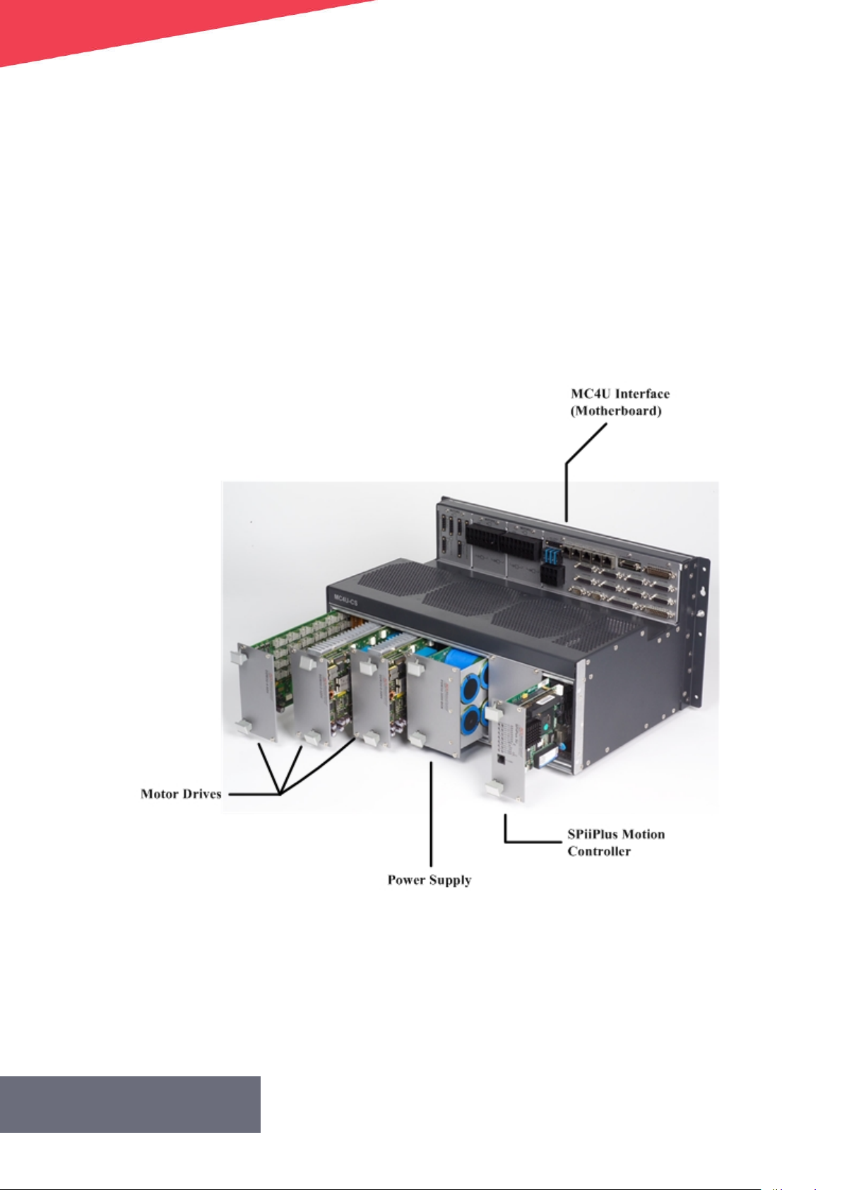
This sectionprovidesdetailed specifications of the MC4U family and its components. The
componentsconsist of:
> SPiiPlusMotion Controller
> PSM3UPowerSupply
> Motor Drive(up to amaximumof 3units)
> MC4UInterface(Motherboard) Connectors
The functionalityof anyspecific MC4UControl Moduleisdetermined by the motherboard thatis
installed. See MC4U Motherboardsfor detailsof thevariousmotherboardsincorporated inthe
MC4UControl Module models.
Version 2.50.D
Figure 2-1. MC4U Components
30
Page 31

MC4UHardwareGuide
2.MC4U Specifications
2.1 MC4UPhysicalSpecifications
2.1.1 MC4U Dimensions
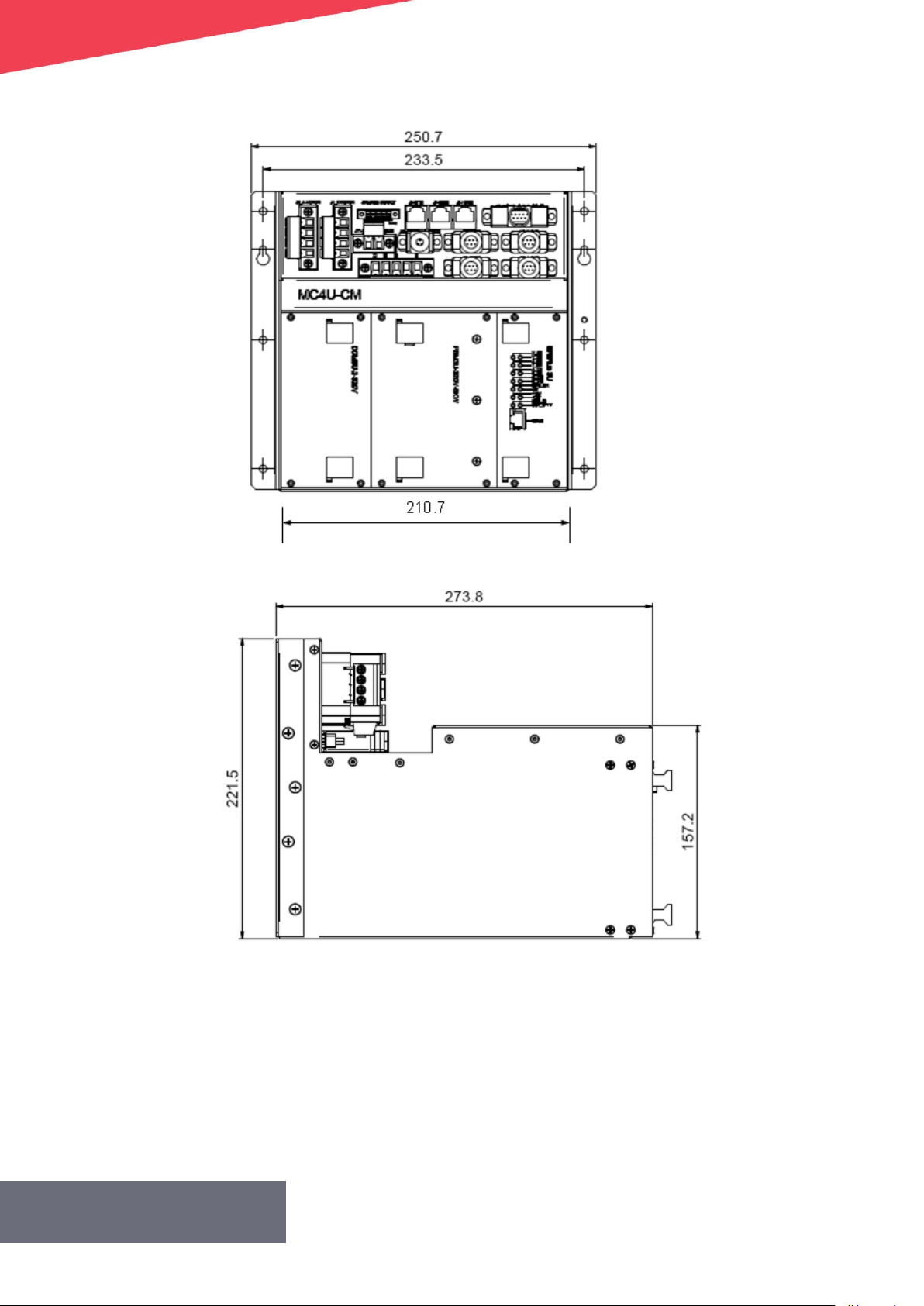
2.1.1.1 MC4U-9-Piano-enc Dimensions
The following table provides the mechanical dimensions ofthe MC4U-9-Piano-enc.
Table 2-1.MC4U-9-Piano-enc Dimensions
Height 221.5 ±1mm
Width 273.8 ±1mm(with extractors 287.3mm)
Length
The following figuredisplaysthe overalldimensions of the MC4U-9-Piano-encunit.
211 ±1mm (withmounting-bracket
250.7±1mm)
Version 2.50.D
31
Page 32
MC4UHardwareGuide
2.MC4U Specifications
Figure 2-2.MC4U-9-Piano-enc Dimensions
2.1.1.2 MC4U-11-Piano-enc Dimensions
The following table provides the mechanical dimensions ofthe MC4U-11-Piano-enc.
Version 2.50.D
32
Page 33

MC4UHardwareGuide
2.MC4U Specifications
Table 2-2. MC4U-11-Piano-encDimensions
Height 221.5±1mm
Width 273.8±1mm (withextractors287.3mm)
Length 276.7±1mm(with mounting-bracket 316.7±1mm)
The following figuredisplaysthe overalldimensions of the MC4U-11-Piano-enc unit.
Figure 2-3.MC4U-11-Piano-enc Dimensions
2.1.1.3 MC4U-13-Piano-AX7Dimensions
The following table provides the mechanical dimensions ofthe MC4U-13-Piano-AX7.
Table 2-3. MC4U-13-Piano-AX7 Dimensions
Height 185 ±0.2mm
Width
Version 2.50.D
> 340±0.2mm(without mounting
33
Page 34

MC4UHardwareGuide
2.MC4U Specifications
brackets)
> 383±0.2mm(withmounting
brackets)
Length 292±1mm
The following figuredisplaysthe overalldimensions of the MC4U-13-Piano-AX7unit.
Figure 2-4.MC4U-13-Piano-AX7 Dimensions
2.1.1.4 MC4U-19-Piano-enc Dimensions
Table 2-4.MC4U-19-Piano-enc Dimensions
The following table provides the mechanical dimensions ofthe MC4U-19-Piano-enc.
Height 221.5±1mm
> 483±1mm (withfront
bracket)
Width
Length 292±1mm
The following figuredisplaysthe overalldimensions of the MC4U-19-Piano-encunit.
Version 2.50.D
> 476 ±1mm(with rear
bracket)
> 436±1mm (withno
bracket)
34
Page 35

MC4UHardwareGuide
2.MC4U Specifications
Figure 2-5.MC4U-19-Piano-enc Dimensions
2.1.1.5 MC4U-22-Piano-enc Dimensions
The following tableprovides the mechanical dimensions ofthe MC4U-22-Piano-enc.
Table 2-5. MC4U-22-Piano-encDimensions
Height 221.5±1mm
> 542±1mm (with rear
Width
Length 292±1mm
The following figuredisplaysthe overalldimensions of the MC4U-22-Piano-encunit.
bracket)
> 502±1mm(with no
bracket)
Version 2.50.D
35
Page 36

MC4UHardwareGuide
2.MC4U Specifications
Figure 2-6.MC4U-22-Piano-encDimensions
2.1.2 MC4U Weight
The MC4U-9-Piano-enc hasa maximum weight of 5.2kg.
The MC4U-11-Piano-enchasa maximum weight of 6.5kg.
The MC4U-13-Piano-AX7 hasamaximum weight of 9.1kg.
The MC4U-19-Piano-enc hasamaximum weight of 11.5 kg.
The MC4U-22-Piano-enc has amaximum weight of 17kg.
2.1.3 MC4U Power Dissipation
The following table provides the power dissipationof the modules for both the lowand high-
power versionsof the MC4U.
Version 2.50.D
36
Page 37

Table 2-6.MC4U Power Dissipation @NominalLoad
Component HeatDissipation
SPiiPlusNT-LT Motion Controller 14W
SPiiPlusNT-HP Motion Controller 18W
SPiiPlusDC-LT Motion Controller 9W
SPiiPlusDC-HPMotion Controller 13W
PSM3U-48V-0.7kW PowerSupply 85W
PSM3U-100V-3KwPowerSupply 100W
PSM3U-320V-4kWPower Supply 70W
PSM3U-320V-8kWPower Supply 135W
MC4UHardwareGuide
2.MC4U Specifications
PSM3U-320V-10kWPower Supply 235W
PSM3U-320V-11kW PowerSupply 186W
PSM3U-320V-20kWPowerSupply 470W
DDM3U-4-06-02Motor Drive 25W
DDM3U-2-320V-5A Motor Drive 87W (for 2axes)
DDM3U-2-320V-10AMotor Drive 138W (for 2axes)
DDM3U-2-320V-15AMotor Drive 226W (for 2axes)
DDM3U-2-30-20Motor Drive 212W(for axis1-nominalload,andaxis2 -halfload)
DDM3U-4-320V-1A Motor Drive 25W
DDM3U-4-320V-2AMotor Drive 45W
DDM3U-4-320V-3AMotor Drive 62W
DDM3U-1-320V-30A-SRMotor Drive 235W
DDM3U-1-320V-45A-SRMotorDrive 346W
2.1.4 MC4UEnvironmental Parameters
The following table provides the environmentalparametersfor MC4Uoperation.
Version 2.50.D
37
Page 38

MC4UHardwareGuide
2.MC4U Specifications
Table 2-7.MC4UEnvironmental Specification
Parameter Value
Ambient Temperature Rated range of operation from 0to +40°C
Environmental conditions:Storage IEC 60721-3-1(class 1K3 and 1M3)
Environmental conditions:Transportation IEC60721-3-2(class2K4and 2M3)
Environmental conditions:Operating IEC60721-3-3 (class 3K3and 3M4)
2.1.5 MC4U Cooling Vents
The number of MC4Ucoolingv ventsdependsonthe MC4Umodel asfollows:
> MC4U-9-Piano-enc -onecooling vent
> MC4U-11-Piano-enc-twocooling vents
> MC4U-13-Piano-AX7 -twocooling vents
> MC4U-19-Piano-enc -threecooling vents
> MC4U-22-Piano-enc -four coolingvents
Eachvent providesamaximum of 120CFMairflow for the internalcooling of the circuit boards
within the mechanicalhousing. The coolingventsoperate off the24Vlogic supply. The cooling
ventscurrent consumption is1Aor less(dependingon the number of vents).
For information regarding cooling vent periodical maintenance, see Replacing Cooling Vents.
2.2SPiiPlusNT/DC MotionControllers
This sectionprovidestechnical detailsof the SPiiPlusNT/DCmotion controllers.For
completedetails, refer tothe SPiiPlusNT/DC Motion Controller Hardware Guide.
The minimum SPiiPlusNT/DC-LT/HP/LDhardware revisionisD and SPiiPlusNT-SC FW
v2.29.04.00.
The MC4Uisavailable inthe following configurations:
Version 2.50.D
38
Page 39

MC4UHardwareGuide
2.MC4U Specifications
Figure 2-7. SPiiPlusNT GeneralView
The SPiiPlusNTandSPiiPlusDCcontrollersdiffer bytheir networking capabilities:
> The SPiiPlusNTservesasa network master:in addition toits regular control ofthe MC4U
axes,itsupportsanEtherCAT port and the control softwarerequired to expandthe
network. Network expansionisprovided by the addition of network elements suchas
otherMC4Us(which containa SPiiPlusDCcontroller), UDMnt, PDMnt,SDMnt and others.
> The SPiiPlusDCservesasa slave controller in aEtherCAT network, serving the local MC4U
axes.Inthisslave role, the MC4Uisanetwork element, being part of larger network
wherebyamaster MC4U (containing aSPiiPlusNT controller) oranNTMcontrolsthe overall
network. The SPiiPlusDChasanincomingport fromaprevious network element from
which itreceives the profilesandcommandsintended for its axes,and outgoing portto
connect the next network element (if exists)andmaintainthe communicationnetwork.
The SPiiPlusDCisphysicallysimilarto the SPiiPlusNT, except that it doesnot have anMPU
board anddoes notinclude EtherCATconnector J3.
A network mustcontainone master and canhave any number ofslaves.
Both motion controller versionshave the following features:
> Controller -the servocontrol algorithm executes atanuncompromising rate of20kHzfor
each axis regardless ofthe number of axes,providing verylarge bandwidth, exceptional
dynamic tracking, fast settling,andexcellent smoothness at low velocities.
The controller ismanufactured under ISO9001 certified quality management system, meeting
stringentsafety andEMCstandardsandisCEmarked.
> Communication Channels-communicationwith the controller through all channelscanbe
done simultaneously:
Version 2.50.D
39
Page 40

MC4UHardwareGuide
2.MC4U Specifications
- The controller communicateswith acomputer hostviaan RS-232 serialchannelor
Ethernet 10/100BaseT channel.
- Inaddition it can communicate withother computers via asecond RS-232 serial
channel (115,200baud)or Ethernet 10/100BaseTchannel.
- The SPiiPlusNTandSPiiPlusDChave 1/2EtherCAT channels, operating at100Mbs.The
EtherCAT connectors are located on the controllers front panel.
> Discrete InterfaceSignals-the controllerscome with digitalandanalog I/Os used for
generalpurpose andfor functional anddedicated purposes.These signalsare accessible
to the user from the MC4U’sconnector panel only.Inaddition, digital inputscanbe used
for hardware-based position registration andoutputs canbe usedto trigger position-
based eventswith sub-µSecdelay accuracy.
Configurationof the digital I/Osare byjumpers onthe SPiiPlusNT/DC controller. See the
appropriate SPiiPlusNT/DCMotionController Hardware Guide for detailed information.
> ACSPL+-complex applicationsareeasyto develop withACSPL+,apowerful,true
multitasking, high-level languagethat isoptimized for motion control applications. Ten
programscan run simultaneously,enabling multiple interacting andsynchronized
processes.ACSPL+enablesimplementationof highly complex motion-time-event
sequences with accurate positioning and timing. The program can run directly on the
controller orcanbe implemented in ahostPCapplication using librariesprovided for C,
C++, COM,and .NET.
> Suite of Tools-powerfulsoftware toolsare provided for setup, tuning, and programming.
Application development isparticularlyeasywith the integrated four-channelsoft scope
andmulti-axismotion simulator.
The SPiiPlusNT/DC controllers are availablein the followingmodels:
> High PerformanceControllers:
- SPiiPlusNT/DC-HP-a high performancedrive controller with 16-bit A2Dfor motor
currentand analog SIN-COS encoder measurements.
- SPiiPlusNT/DC-LD-a high performancedrive controller based onthe SPiiPlusNT/DC-HP
with an additional module for 16-bit analog commandstolinear drives.
> Light Controllers
- SPiiPlusNT/DC-LT-aneconomicaldrive controller that uses12-bit A2Dfor motor
currentand analog SIN-COS encoder measurements.
2.2.1 SPiiPlusNT/DC Motion ControllersFeatures
The SPiiPlusNT/DC features aredescribed inthe following tables:
The CTIMEvalues inare for aSPiiPlusNT systemwith additionalslave drives, including MC4U slave
drives with SPiiPlusDC controllers.
Version 2.50.D
40
Page 41

SPiiPlusADK Suite 2.50 Hardware Guide
2.MC4U Specifications
Table 2-8. CTIMEValuesfor MC4UNT SPiiPlusNT-LT/HP/LD/NP (Rev. D and later) Controller
Maximum
Number of
Controller
(tobe insertedinto MC4UNT)
SPiiPlus NT-LT-4 4 4 10 4 10 √ ⁽⁴⁾ ⁽⁵⁾ - - - 1 -
SPiiPlus NT-LT-4 4 8 10 8 10 √ ⁽⁴⁾ ⁽⁵⁾ - - - 1 -
SPiiPlus NT-LT-4 4 16 16 16 16 √⁽⁴⁾ ⁽⁵⁾ - - - 1 -
SPiiPlus NT-LT-4 4 32 32 32 32 √ ⁽⁴⁾ ⁽⁵⁾ - - - 1 -
SPiiPlus NT-LT-4 4 64 64 64 64 √ ⁽⁴⁾ ⁽⁵⁾ - - - 1 -
SPiiPlus NT-LT-8 8 8 10 8 10 √ ⁽⁴⁾ ⁽⁵⁾ - - - 1 -
SPiiPlus NT-LT-8 8 16 16 16 16 √ ⁽⁴⁾ ⁽⁵⁾ - - - 1 -
SPiiPlus NT-LT-8 8 32 32 32 32 √ ⁽⁴⁾ ⁽⁵⁾ - - - 1 -
SPiiPlus NT-LT-8 8 64 64 64 64 √ ⁽⁴⁾ ⁽⁵⁾ - - - 1 -
SPiiPlus NT-HP-4 /NT-LD-4 /NT-NP-2 4 4 10 4 10 √ ⁽⁴⁾ ⁽⁵⁾ √ ⁽⁴⁾ ⁽⁵⁾ √ ⁽⁴⁾ ⁽⁵⁾ √ ⁽⁴⁾ ⁽⁵⁾ 0.5 √
SPiiPlus NT-HP-4 /NT-LD-4 /NT-NP-2 4 8 10 8 10 √ ⁽⁴⁾ ⁽⁵⁾ √ ⁽⁴⁾ ⁽⁵⁾ √ ⁽⁴⁾ ⁽⁵⁾⁾ √ ⁽³⁾ ⁽⁵⁾ 0.5 √
SPiiPlus NT-HP-4 /NT-LD-4 /NT-NP-2 4 16 16 16 16 √⁽⁴⁾ ⁽⁵⁾ √ ⁽⁴⁾ ⁽⁵⁾ √ ⁽³⁾ ⁽⁵⁾ - 0.5 √
SPiiPlus NT-HP-4 /NT-LD-4 /NT-NP-2 4 32 32 32 32 √ ⁽⁴⁾ ⁽⁵⁾ √ ⁽⁴⁾ ⁽⁵⁾ - - 0.5 √
SPiiPlus NT-HP-4 /NT-LD-4 /NT-NP-2 4 64 64 64 64 √ ⁽⁴⁾ ⁽⁵⁾ - - - 1 √
SPiiPlus NT-HP-8/ NT-LD-8/ NT-NP-4 8 8 10 8 10 √ ⁽⁴⁾ ⁽⁵⁾ √ ⁽⁴⁾ ⁽⁵⁾ √ ⁽⁴⁾ ⁽⁵⁾ √ ⁽³⁾ ⁽⁵⁾ 0.5 √
SPiiPlus NT-HP-8/ NT-LD-8/ NT-NP-4 8 16 16 16 16 √⁽⁴⁾ ⁽⁵⁾ √ ⁽⁴⁾ ⁽⁵⁾ √ ⁽³⁾ ⁽⁵⁾ - 0.5 √
SPiiPlus NT-HP-8/ NT-LD-8/ NT-NP-4 8 32 32 32 32 √ ⁽⁴⁾ ⁽⁵⁾ √ ⁽⁴⁾ ⁽⁵⁾ - - 0.5 √
SPiiPlus NT-HP-8/ NT-LD-8/ NT-NP-4 8 64 64 64 64 √ ⁽⁴⁾ ⁽⁵⁾ - - - 1 √
⁽¹⁾Ifthe MPU processing power is not sufficient,thenuse the MC4Udc version with an externalSPiiPlusNTM-yy-xx-xx-xx-xxx-H-xor SPiiPlusEC-yy-xx-xx-xx-xxx-x-xtypecontroller.
⁽²⁾Ifthe MPU processing power is not sufficient,thenuse the UDMpm /UDMba /UDMhp / UDMhv versionwith anexternal SPiiPlusNTM-yy-xx-xx-xx-xxx-H-xor SPiiPlusEC-yy-xx-xx-xx-xxx-x-xtype
controller.
⁽³⁾2-axes Extended Segmented Motion(XSEG) with limitations: a.Segment length> 5ms,b. IMM VEL =… command shouldn't be used
⁽⁴⁾6-axes Extended Segmented Motion(XSEG) with limitation: Segment length >1ms. Theuser's responsibilityis to ensure that theUSAGEdoesn't exceed 80%.
⁽⁵⁾NetworkBoost (RingTopology) with limitations: a.CTIME=1 msec -up to64 axes b.CTIME=0.50msec -up to 24axes c.CTIME=0.25msec - upto 8axes d. CTIME =0.20 msec -up to 4axes
*Supported orderingoption.
**Upto64 buffers supported with ordering option.
Number
ofBuilt-
inDrives
Maximum
Number
ofAxes
DefaultNumberof
AvailableACSPL+
Buffers**
Simultaneously
Running
Motors
ACSPL+
Buffers
1(msec)
2(msec)
Controller CycleTime
0.50
(msec)
0.25
(msec)*
0.20
(msec)*
Default
Value
(msec)
ServoBoost
Supported
Version 2.50.D
41
Page 42

Table 2-9.SPiiPlusNT/DC-LT/HP/LD AdditionalFeatures
HWFeature SPiiPlusNT/DC-LT/HP/LD Remarks
ProfileGeneration
Motion Profile
generation
rate
Feedback
Incremental
Digital Encoder
1, 2,4or 5kHz
One per axis: A&B,I;UP/DN,I;
CLK/DIR,I.
Type:RS-422
Max. rate: 40millionencoder
counts/sec.
MC4UHardwareGuide
2.MC4U Specifications
Sin-Cos
Encoder
(optional)
One per axis
SPiiPlusNT/DC-HP/LD:
Multiplication factor: Fromx4to
x65,536.
Rate:HPversion:Up to500*10³ sine
periods/sec;
LDversion:4*10⁶sine periods/sec.
Sin-Cosoffset,gain,phase
compensation: programmable with
automatic calibration.Offset is
hardware compensated, +/-50%of
signalrange.
Maximum acceleration: 4x10⁸sine
periods/sec².
SPiiPlusNT/DC-LT:
Multiplication factor: Fromx4to
x4,096Sin-Cosoffset gain,phase
compensation: programmable with
automatic calibration.Rate:250*10³
sine periods/sec.
Maximum acceleration: 4x10⁸sine
periods/sec².
Hallinputs
Absolute
encoder
Version 2.50.D
Set of three per axis.
Single-ended, 5V, source, opto-
isolated.
Input circuit current: <7mA.
SupportsEnDat2.1/2.2 (Digital
only), Smart-ABS, Panasonic, Biss-C,
SSI,Hiperface,SanyoDanki.
42
Page 43

HWFeature SPiiPlusNT/DC-LT/HP/LD Remarks
Indices:X(0),Y(1), (Z(4) and T(5).
DriveInterface
MC4UHardwareGuide
2.MC4U Specifications
Analog
commands
(SPiiPlusNT/DC-
LDonly):
PWMdrive
commands
Drive Current
Feedback
External drives
Two phasesper axis.
Type:±10V,differential, 16bit
resolution.
Offsetcompensation:
programmable, 0.3mV resolution.
Three phasesper axis.
Control algorithm: digital PIfilters
with field oriented control and
spacevector modulation.
PWMfrequency:40kHz onthe
motor.
Two phasesper axis.
Current loop sampling rate:20kHz.
Current feedback resolution:
SPiiPlusNT/DC-HP/LD:16bit.
SPiiPlusNT/DC-LT:12bit.
SPiiPlusNT/DC-LD:twophasesper
axis
Drive command analogoutputs
are supported onlyby the
SPiiPlusNT/DC-LDproduct.
Supported only byfollowing
motherboards:
> MB5U-Z
> MB5U-YYYY
DigitalI/O
SafetyInputs:
Emergency
stop input
Left andright
limit inputs
DigitalInputs:
> MB5U-ZZZ
> MB5U-ZZW
One per controller.
Type:two-terminal,sink orsource,
opto-isolated.
One pairper axis.
Type:single-ended, sink (default)
or source, configurable by jumper,
opto-isolated.
Supply: 5Vor 24V.
Input current: <15mA.
Version 2.50.D
43
Page 44

HWFeature SPiiPlusNT/DC-LT/HP/LD Remarks
Eight.
MC4UHardwareGuide
2.MC4U Specifications
General
Purpose Inputs
MARK(position
capture) inputs
DigitalOutputs
General
purpose
outputs
Type:single-ended, 5Vor24V,sink
(default)or source,opto-isolated.
Input current: <15mA.
Up to four.
Type:RS-422.
Propagation delay:<0.1 μsec.
Eight.
Type:single-ended, 5Vor24V,sink
(default)or source,opto-isolated.
Output current:100mA per output.
One per axis.
Four additionalMARKinputs
(MARK2),single-ended and opto-
isolated, are availablethrough
generalpurpose digital inputs
IN4,IN5, IN6 andIN7
Refer to PEGand MARK
Operations Application Notesfor
detailed information.
Dependsoncontroller
configuration.
Dualusage,canbe usedas
MechanicalBrake.
Mechanical
Brake Outputs:
General purpose digital outputs can be configured asMechanicalBrake Outputs.
Dynamicbrake signalisavailable onlyfor internal MC4Udrivers and isnot accessibleasan
externalsignal.
PEGpulse
outputs:
PEGstate
outputs
Type:single-ended, 5V,source
only, opto-isolated
Output current:7mA per output.
Six.
Type:RS-422.
Propagation delay:<0.1μsec.
PEGpulsewidth: 25nsec to 1.7msec.
PEGposition accuracy: ±1count at
speeds up to18x10⁶ counts/sec.
Up to six.
Type:RS-422.
Propagation delay:<0.1μsec.
Default configurationisdynamic
brake.
Refer to PEGand MARK
Operations Application Notesfor
detailed information.
Refer to PEGand MARK
Operations Application Notesfor
detailed information.
Version 2.50.D
44
Page 45

HWFeature SPiiPlusNT/DC-LT/HP/LD Remarks
Up to three.
HSSIExpansion
Channels
AnalogI/O
Analog Inputs
General
Purpose Inputs
Eachchannel provides64 inputbits
and64 output bits per channel,
sampled and updatedevery
50μsec.Type: RS-422.
Up to 16.
Type:1Vptp, differential.
Resolution and SNR:
SPiiPlusNT-HP/LD:16bit, SNR>72db.
SPiiPlusNT-LT: 12bit, SNR>52db.
SPiiPlusNT-HP/LD:
Four dedicated generalpurpose
inputs.
Type:±10V,differential.
Resolution: 16bits.
SPiiPlusNT-LT:
Up to four (whenaxesnumber 3
and/ or 7Sin-Cosencoders arenot
used.
Type:±10V,differential.
Resolution: 12bits.
Unused Sin-Cosencoder inputs
canbe usedasgeneral purpose
analoginputs.
MC4UHardwareGuide
2.MC4U Specifications
General
Purpose
Outputs
CommunicationChannels
Serial
Ethernet
EtherCAT
2,4.
Type:±10V,PWM filtered.
Resolution: 10bit.
SPiiPlusNTonly:
Two.
RS-232.
Up to 115,200bps
SPiiPlusNTonly:
One.
TCP/IP, 10/100Mbits/sec.
SPiiPlusNT:Oneor twomaster
ports.
SPiiPlusDC:Oneinput, one output.
SPiiPlusNTonly:Simultaneous
communication through all
channelsisfully supported.
Modbus protocol asmaster or
slave issupported via all
channels
SPiiPlusNTonly:Optional
network failure detection and
recovery with ring topology.
Version 2.50.D
45
Page 46

HWFeature SPiiPlusNT/DC-LT/HP/LD Remarks
MPU(SPiiPlusNTonly)
Processor Intel® Atom™ N26001.6 GHz
MC4UHardwareGuide
2.MC4U Specifications
Memory
Powerup Time
Environment& Standards
Operating
Temperature
Storage
Temperature
Humidity 90%RH,non-condensing
Standards
RAM:1GB
FlashNVmemory:1GB
25-100sec. according to system
andnetwork configuration
0˚Cto 55˚C
40˚Cto 70˚C
CE(EMC),ULcertified and RoHS
compliant
2.2.2 SPiiPlusNT/DC Indicators
The indicators arelocated onthe front panel of the module and indicate the statusof the power
supplies andaxesas showninthe example giveninFigure 2-8
Version 2.50.D
46
Page 47

MC4UHardwareGuide
2.MC4U Specifications
Figure 2-8.SPiiPlusNT/DC Indicators(SPiiPlusNTshown)
The indicators aredetailed in Table2-10.
Table 2-10.SPiiPlusNT/DCIndicators
Label Description Remarks
EtherCAT status
IN
OUT
Axis#
(Axis)
MPU_
ON
Two yellowLEDs:
> On:Linkconnected 100MHzspeed
> Blink: transmitter isactive
> Off:not connected
AxisStatus
Four -onefor each axis
Bicolor (Green/Red)LEDs:
> Green On:axis enabled
> Red On:axis failed
> Off:axis disabled
MPUStatus
Bicolor (Green/Red)LED
> Red LED
Version 2.50.D
47
Page 48

Label Description Remarks
- On:Communication fault
> Green LED
- On:Control Unit functioning
properly
- Blink: Processor and
communicationsfunctioning
properly
- Off:Noconnection with MPU
-5VStatus
MC4UHardwareGuide
2.MC4U Specifications
-5V
+12V
-12V
IO_PWR
SFTY_
PWR
Green LED
> On:-5Vavailable
> Off:No-5V
+12V Status
Green LED
> On:+12V available
> Off:No+12V
-12VStatus
Green LED
> On:-12Vavailable
> Off:No-12V
I/O Power Status
Green LED
> On:voltage isavailable
> Off:Novoltage
Safety Power Status
Green LED
> On:voltage isavailable
> Off:Novoltage
Two LEDs:Green andYellow
Green LED
J3
> On:Linkpresent
> Blink: Linkactive
Yellow LED
> ON:communicationat100MHz
SPiiPlusNT-LT/HP/LDRevD and
later only.
2.3PSM3UPower Supplies
There are sixtypesof PSM3U power supplies. These powersupplies mustbe matched tothe
motherboard installedin the MC4U Control Module (seeTable 2-11). Allpower suppliesneed two
Version 2.50.D
48
Page 49

input voltage supplies:
> 24Vdc inputsupply for internal logiccircuit
> AC drivesupply for motor operation
The 24Vdc inputpower supply should notbe connected to aDC distribution network;
anexternal AC/DC supply witha24Vdc,5Aoutput must be used.
Whenever anyMC4Umaintenance has to beperformed and aPSM3U-48V-xx power
supply isinstalled,after disconnectingthe unit from external power, awaiting period
of 30minutes mustbe observed inorderto allowcomplete voltagedischarge before
disassembling any of the MC4Ucomponents. Otherwise damage couldoccur to the
unit.
Table 2-11. PSM3U Power Supplies-General
Nominal
Input
Power
Supply
Number
ofInput
Phases
Voltage
Range
[Vrms]
-15%
+10%
MaxCont.
InputCurrent
PerPhase
[Arms]
MaxCont.
InputPower
[W]
MC4UHardwareGuide
2.MC4U Specifications
Applicable
Motherboard
PSM3U-
48V-
0.5kW
PSM3U-
48V-
0.7kW
PSM3U-
48V-
1.4KW
100-
240
1
1
1
phase
to
neutral
100-
240
phase
to
neutral
100-
240
phase
to
neutral
3.2 600
3.1 900
6.2 1800
MB5U-CONT-
PSMB5U-
YYYYMB5U-
ZZZMB5U-
ZVMB5U-ZZ
MB5U-CONT-
PSMB5U-
YYYYMB5U-
ZZZMB5U-
ZVMB5U-ZZ
MB5U-CONT-
PSMB5U-
ZZWMB5U-
ZVMB5U-ZZ
Version 2.50.D
49
Page 50

Power
Supply
Number
ofInput
Phases
Nominal
Input
Voltage
Range
[Vrms]
-15%
+10%
MaxCont.
InputCurrent
PerPhase
[Arms]
MaxCont.
InputPower
[W]
MC4UHardwareGuide
2.MC4U Specifications
Applicable
Motherboard
PSM3U-
48V-4KW
PSM3U-
320V-
8kW
100-
240
1
3
1
3
phase
to
neutral
100-
240
phase
to
phase
100-
240
phase
to
neutral
100-
240
phase
to
phase
13 3000
11 4200
25.8with
MB5U-CONT-
PS2,MB5U-ZZ,
MB5U-ZV,
MB5U-Z
24 with
MB5U-CONT-
PS, MB5U-
YYYY, MB5U-
ZZZ,MB5U-
ZZW
25.8with
MB5U-CONT-
PS2,MB5U-ZZ,
MB5U-ZV,
MB5U-Z
24 with
MB5U-CONT-
PS, MB5U-
YYYY, MB5U-
ZZZ,MB5U-
ZZW
6200with
MB5U-CONT-
PS2,MB5U-ZZ,
MB5U-ZV,
MB5U-Z
5760with
MB5U-CONT-
PS, MB5U-
YYYY, MB5U-
ZZZ,MB5U-
ZZW
10730with
MB5U-CONT-
PS2,MB5U-ZZ,
MB5U-ZV,
MB5U-Z
9977 with
MB5U-CONT-
PS, MB5U-
YYYY, MB5U-
ZZZ,MB5U-
ZZW
MB5U-CONT-
PS
MB5U-CONT-
PS2
MB5U-Z
MB5U-ZV
MB5U-ZZ
MB5U-YYYY
MB5U-ZZZ
MB5U-ZZW
MB5U-CONT-
PS
MB5U-CONT-
PS2
MB5U-Z
MB5U-ZV
MB5U-ZZ
MB5U-YYYY
MB5U-ZZZ
MB5U-ZZW
Version 2.50.D
50
Page 51

Power
Supply
Number
ofInput
Phases
Nominal
Input
Voltage
Range
[Vrms]
-15%
+10%
MaxCont.
InputCurrent
PerPhase
[Arms]
MaxCont.
InputPower
[W]
MC4UHardwareGuide
2.MC4U Specifications
Applicable
Motherboard
PSM3U-
320V-
10kW
32with
MB5U-CONT-
PS2,MB5U-ZZ,
100-
240
1
3
phase
to
neutral
100-
240
phase
to
phase
MB5U-ZV,
MB5U-Z
24 with
MB5U-CONT-
PS, MB5U-
YYYY, MB5U-
ZZZ,MB5U-
ZZW
32with
MB5U-CONT-
PS2,MB5U-ZZ,
MB5U-ZV,
MB5U-Z
24 with
MB5U-CONT-
PS, MB5U-
YYYY, MB5U-
ZZZ,MB5U-
ZZW
7680with
MB5U-CONT-
PS2,MB5U-ZZ,
MB5U-ZV,
MB5U-Z
5760with
MB5U-CONT-
PS, MB5U-
YYYY, MB5U-
ZZZ,MB5U-
ZZW
13300with
MB5U-CONT-
PS2,MB5U-ZZ,
MB5U-ZV,
MB5U-Z
9980with
MB5U-CONT-
PS, MB5U-
YYYY, MB5U-
ZZZ,MB5U-
ZZW
MB5U-CONT-
PS
MB5U-CONT-
PS2
MB5U-Z
MB5U-ZV
MB5U-ZZ
MB5U-YYYY
MB5U-ZZZ
MB5U-ZZW
PSM3U-
320V-
11kW
Version 2.50.D
100-
240
1
3
phase
to
neutral
100-
240
phase
to
phase
30(24
depending on
motherboard
setup)
30(24
depending on
motherboard
setup)
51
6900(5500
depending on
motherboard
setup)
MB5U-CONT-
PSMB5U-Z
12000(9600
depending on
motherboard
setup)
Page 52

Power
Supply
Number
ofInput
Phases
Nominal
Input
Voltage
Range
[Vrms]
-15%
+10%
MaxCont.
InputCurrent
PerPhase
[Arms]
MaxCont.
InputPower
[W]
MC4UHardwareGuide
2.MC4U Specifications
Applicable
Motherboard
PSM3U-
320/48V-
8/0.7kW
PSM3U-
320V-
20kW
100-
240
1
3
1
3
phase
to
neutral
100-
240
phase
to
phase
100-
240
phase
to
neutral
100-
240
phase
to
phase
28.5(24with
the applicable
motherboard)
24.4 (24with
the applicable
motherboard)
54 10600
76 30000
6700(5500
with the
applicable
motherboard)
9400(9200
with the
applicable
motherboard)
MB5U-CONT-
PSMB5U-
ZZWMB4U-
ZZW-AX7
The following isabrief description ofeach power supply:
> PSM3U-48V-0.7kW
The PSM3U-48V-0.7kW isalow-power, regulated powersupply andsupplies:
- One 51VdcnominalBUS voltage,up to700W(motor supply), providing power for
motor drivers suchasDDM3U-4 drive and the like. (If 700Wis not enough power, use
the PSM3U-48V-1.4kWpower supply.)
- All voltagesfor the SpiiPlusMotion Controller.
The PSM3U-48V-0.7kW issupplied from:
- Single AC externalpower supply within the voltage fluctuation range:85-265Vac
- 24Vdc±10% for logicsupply
> PSM3U-320V-8kW
The PSM3U-320V-8kWisahigh-power, non-regulated power supply andsupplies:
Version 2.50.D
52
Page 53

MC4UHardwareGuide
2.MC4U Specifications
- VACinx1.4 nominalBUS voltage,up to8.3kW (motor supply), providing power for the
motor drivers suchasDDM3U-2 and the like.(If 8.3kWisnot enough power,use the
PSM3U-320V-11kW power supply.)
- All voltagesfor SpiiPlusMotion Controller.
The PSM3U-320V-8kWissupplied from:
- Single or three-phase AC external powersupply within the voltagefluctuation range
85-265Vac
- 24Vdc ±10%for logic supply
> PSM3U-48V-1.4kW
The PSM3U-48V-1.4kWisalow-powerregulated powersupply, withdual DCbusvoltageoutputs
(up to 1.4kW), and supplies:
- Two 51VdcnominalBUS voltageoutputs,upto 700W(motor supply), for each output
for the motor driverssuch asDDM3U-4 or the like.
- All voltagesfor the SpiiPlusMotion Controller.
The PSM3U-48V-1.4kWissupplied from:
- Single AC externalpower supply within the voltage fluctuation range85-265Vac
- 24Vdc ±10%for logic supply
> PSM3U-320V-11kW
The PSM3U-320V-11kW isahigh-power, non-regulated power supply, withdualDC busvoltage
outputs(up to11 kW)andsupplies:
- Two outputs, VACin x1.4 nominalBUS voltageup to8.3kW for each outputand upto
12kW for both outputs simultaneously,for the motor drivers suchasDDM3U-2 orthe
like.
- All voltagesfor SpiiPlusMotion Controller.
The PSM3U-320V-11kW issupplied from:
- Single or three-phase AC external powersupply within the voltagefluctuation range
85-265Vac
- 24Vdc ±10%for logic supply
> PSM3U-320/48V-0.7/8kW
The PSM3U-320/48V-0.7/8kW isrequired ifDDM3U-2and DDM3U-4motor drivers are
installed together inthe 19” MC4U.
The PSM3U-320/48V-0.7/8kW isadualoutput, mixed voltagespower supply, high (upto 8kW)and
low-power (upto 0.7 kW) andsupplies:
- VACinx1.4 nominalBUS voltage,up to8 kW(motor supply), for the DDM3U-2 orthe
- 320VdcnominalBUS voltage,up to 8kW(motor supply), for the DDM3U-2
- 48Vdc nominal BUS voltage, upto 700W (motor supply), for the DDM3U-4 drive or the
- All voltagesfor SpiiPlusMotion Controller
Version 2.50.D
like
like
53
Page 54

MC4UHardwareGuide
2.MC4U Specifications
The PSM3U-320/48V-0.7/8kW issupplied from:
- Single or three-phase AC external powersupply within the voltagefluctuation range
85-265Vac.
- 24Vdc ±10%for logic supply.
When usingboth lowandhigh-power suppliesinthe same unit, the lowvoltageis
connectedto J30(V2) onthe motherboard, and the high voltage isconnected to J29
(V1) onthe motherboard.
> PSM3U-320V-20kW
The PSM3U-320V-20kWisanunregulated power supply (it isa combinationof twoPSM3U-320V-
10KW powersupplies). This supply isused to generate the two separateDC BUSvoltages(motor
supply) for the motor drivers (PWMor linear).
The PSM3U-320V-20kWissupplied from aone-or three-phase AC external power supply withinthe
voltage rangeof 100-230Vacnominaland generatestwoseparate DCBUS output voltagesof
140Vdc to320Vdc nominal.
2.3.1 PSM3U Specifications
2.3.1.1 PSM3U-48V-XXkWPowerSupply
The following table liststhe PSM3U-48V-XXkWspecifications.
Table 2-12.PSM3U-48V-XXkWLow-Power PSSpecifications
Parameter Description Remarks
AC Input voltage (drivesupply):
> Fluctuation Range:single phase 85-
265Vac
Input frequency:
> Nominalfrequency:50Hz
Power Input
> Minimumfrequency: 47Hz
> Maximum frequency: 63Hz
Inrush current: 50A peak
Maximum input current:
> 10.67A @85Vac (for 700W unit)
> 21.3A @85Vac(for 1400Wunit)
Efficiency:81%
Power
Output
Version 2.50.D
Maximum output current:
For 700Wunit:
> 14A (continuous and peak) @
Vin=265Vac
> 10A continuous14A peak @
Vin=85Vac
54
Page 55

MC4UHardwareGuide
2.MC4U Specifications
Parameter Description Remarks
Output voltage:
> Nominalvoltage:51Vdc
> Minimumvoltage:45Vdc
> Maximum voltage:57Vdc
Output power:
> Maximum output power: 700W
(continuous and peak) for 700Wunit
@Vin=265Vac and500W continuous
@Vin=85Vac
The Logic Supply isused to generate all
necessary lowvoltages for the SPiiPlus
Motion Controller.
The Logic Supply ispowered from an
Logic Supply
external24Vdc control supply, andhasthe
following characteristics:
> Input voltage:
- Nominalvoltage:24Vdc
- Minimumvoltage:
21.6Vdc
- Maximum voltage:
26.4Vdc
> Input power: 55W, max.
> Input current: 2.9A, max., @21.6V
control supply input voltage
> Supply inrush current
- Maximum inrush
currentvalueisless
than 4Armsmeasured
within first 400ms after
logic supply input
voltage isapplied.
- After the first 400ms,
the inrush current value
continuously decreases
anddropsbelow2.9A
within 1sec.
> Supply input voltage ripple:
- Maximum input voltage
rippleamplitude: 5V
peak-to-peak at100Hz
frequency
- Inanycondition: the
input voltage level
including the voltage
rippleamplitude must
Version 2.50.D
55
Page 56

MC4UHardwareGuide
2.MC4U Specifications
Parameter Description Remarks
not be lower than21.6V
andnot greater than
26.4V
I2C Circuit
±12Vsupply
for third
party drive
(DC/DC unit)
Power
Supply Fault
output
signal
See I2CCircuit.
The PSM3U-48V-0.7kW PowerSupply
provides the option for supportingadditional
±12Vfor third party drives.
This signal goes to“0” logiclevel and remains
in thislevelif one ofthe power supply
protection circuits isactivated.
2.3.1.2 PSM3U-320V-8kW Power Supply
The following table liststhe PSM3U-320V-8kWspecifications.
For overvoltage fault
recovery,the AC input
must beremoved and
reapplied.
Version 2.50.D
56
Page 57

MC4UHardwareGuide
2.MC4U Specifications
Table 2-13.PSM3U-320V-8kWHigh-PowerPS Specifications
Parameter Description Remarks
Input voltagefluctuation range:
> Single phase 85-265Vac input
(phase-to-neutral)
> Three phase 85-265Vac input
(phase-to-phase)
Input frequency:
> Nominalfrequency:50Hz
> Minimumfrequency: 47Hz
Power Input
> Maximum frequency: 63Hz
Inrush current:
> Maximum inrush current valueis
3.75Arms measured for the first
20msafter power supply input
voltage isapplied.
> After the first 20ms, the inrush
currentvaluecontinuously
decreasesanddrops below
1.3Armswithin 5sec.
Efficiency:
The maximuminput
currentfor the AC
input (drive supply)
must notbe more
than 30A due to the
AC input in
connector J14 of the
MC4UInterface(see
J14 -DriveSupply
Voltage Connector)
> 68% -for 85 -265Vac single phase
supply
> 68% -for 195- 265Vac three
phase supply
Input Power:see Table 2-14 andTable 2-15.
Input Current: see Table 2-16 andTable 2-
17.
Parameter Description Remarks
Maximum output current:
> 16A continuous, 32A peak for 85-
130Vac single phaseinput supply
> 15.5A continuous,31A peakfor
Power Output
195 -265Vacsinglephase input
supply
> 23Acontinuous, 62Apeak for 195
-265Vac three phase input
supply
Version 2.50.D
57
Page 58

MC4UHardwareGuide
2.MC4U Specifications
Parameter Description Remarks
Output Voltage: see Table2-18,Table 2-19
andTable 2-20.
Output Power: see Table2-21,Table 2-22,
andTable 2-23.
The Logic Supply isused to generate all
necessary lowvoltages for the SPiiPlus
Motion Controller.
The Logic Supply ispowered from an
external24Vdc control supply, andhas
the following characteristics:
> Input voltage:
- Nominalvoltage:24Vdc
- Minimumvoltage:21.6Vdc
- Maximum voltage:26.4Vdc
> Input power: 55W, max.
> Input current: 2.9A, max., @21.6V
control supply input voltage
> Supply inrush current
- Maximum inrush current
Logic Supply
> Supply input voltage ripple:
valueislessthan4Arms
measured within first 400ms
after logic supply input
voltage isapplied.
- After the first 400ms, the
inrush current value
continuously decreases and
dropsbelow2.9A within
1sec.
- Maximum input voltage
rippleamplitude: 5Vpeak-to-
peak at100Hzfrequency
- Inanycondition: the input
voltage levelincluding the
voltage ripple amplitude
must notbe lower than21.6V
andnot greater than 26.4V.
Version 2.50.D
58
Page 59

MC4UHardwareGuide
2.MC4U Specifications
Parameter Description Remarks
The internal
regeneration
resistor must be
disconnected from
Power Supply J9
connector;
otherwiseit will
work inparallelwith
the externalresistor
andheat the power
supply heatsink for
no reason.
This signal issent to
the SPiiPlusMotion
Controller over the
I2C bus.
External
Regeneration
Power Supply Fault
output signal
Regenerationcircuit activateswhenDC
BUS output voltage exceeds 400V±3%
(388-412V)
External regenerationresistor >15Ω
This signal goes to“0” logiclevel and
remains inthislevel ifone of the power
supply protection circuit isactivated.
A self-reset circuit generatesa pulse
every 130mSecto reset the signalto “1”
logic levelwhen the faultcondition
disappears.
Discharge time
Paramet
er
Input
power
nominal
(Pin), [W]
Input
power
peak (Pin
peak),
[W]
Parameter 195Vac 230Vac 265Vac
The 320vsupplieshave anactivedumper
that discharges the voltageto below50v
within lessthan3seconds.
Table 2-14.Maximum Input Power @Single Phase Input 85 -265Vac
85Vac
1858.2
6
1732.2
6
Table 2-15.Maximum InputPower @Three PhaseInput 195-265Vac
100Va
c
2240.
83
2455.0
8
115Vac 130Vac
2814.
93
3539.
31
3388.9
4
4623.5
4
195Va
c
5350.4
3
8437.
97
230Vac 265Vac
6462.5
7
10538.
67
7574.7
0
12639.
37
Version 2.50.D
Input power nominal (Pin), [W] 8601.73 10251.99 11902.26
Input power peak(Pin peak),[W] 19100.49 23301.88 27503.27
59
Page 60

MC4UHardwareGuide
2.MC4U Specifications
Table 2-16.Maximum Input Current @Single Phase Input 85- 265Vac
Paramete
r
Input
current
nominal
(Iin),
[Arms]
Input
current
peak (Iin
peak),
[Arms]
85Va
c
21.55 22.93 24.48 25.63 27.37 28.10 28.64
20.08 25.12 30.78 34.96 43.16 45.82 47.79
Table 2-17.Maximum Input Current @ThreePhaseInput 195-265Vac
Parameter 195Vac 230Vac 265Vac
Input current nominal(Iin),[Arms] 25.40 25.73 25.98
Input current peak
(Iinpeak), [Arms]
100Va
c
115Va
c
130Va
c
56.41 58.49 60.03
195Va
c
230Va
c
265Va
c
Table 2-18.Output Voltage @SinglePhaseInput 85- 130Vac
Parameter 85Vac 100Vac 115Vac 130Vac
Maximum output voltage
(Vout_max),[Vdc]
Nominaloutput voltage@nominaloutput
current16A (Vout_nom), [Vdc]
Minimumoutput voltage @peakoutput
current32A (Vout_peak), [Vdc]
Table 2-19.Output Voltage @SinglePhaseInput 195-265Vac
Parameter 195Vac 230Vac 265Vac
Maximum output voltage
(Vout_max),[Vdc]
Nominaloutput voltage@nominaloutput current 15.5A
(Vout_nom), [Vdc]
118.98 135.24 159.63 184.03
78.98 95.24 119.63 144.03
38.98 55.24 79.63 104.03
273.48 322.27 371.06
234.73 283.52 332.31
Version 2.50.D
60
Page 61

MC4UHardwareGuide
2.MC4U Specifications
Parameter 195Vac 230Vac 265Vac
Minimumoutput voltage @peakoutput current 31A
(Vout_peak),[Vdc]
Table 2-20. Output Voltage @Three PhaseInput 195- 265Vac
Parameter 195Vac 230Vac 265Vac
Maximum output voltage
(Vout_max),[Vdc]
Nominaloutput voltage@nominaloutput current 23A
(Vout_nom), [Vdc]
Minimumoutput voltage @peakoutput current 62A
(Vout_peak),[Vdc]
Table 2-21.Output Power @Single Phase Input 85-130Vac
Parameter 85Vac 100Vac 115Vac 130Vac
Nominaloutput power @nominaloutput
current16A (Pout_nom), [W]
1263.61 1523.83 1914.15 2304.48
195.98 244.77 293.56
273.48 322.27 371.06
254.31 303.10 351.89
221.81 270.60 319.39
Peak output power @peakoutput current
32A(Pout_peak),[W]
Table 2-22. Output Power @SinglePhaseInput 195-265Vac
Parameter 195Vac 230Vac 265Vac
Nominaloutput power @nominaloutput current 15.5A
(Pout_nom), [W]
Peak output power @peakoutput current 31A(Pout_
peak), [W]
Table 2-23. Output Power @Three PhaseInput 195-265Vac
Parameter 195Vac 230Vac 265Vac
Nominaloutput power @nominaloutput current
23A(Pout_nom), [W]
Peak output power @peakoutput current 62A
(Pout_peak),[W]
1247.23 1767.66 2548.31 3328.95
3638.30 4394.55 5150.80
6075.34 7587.84 9100.34
5849.18 6971.36 8093.53
13752.35 16777.35 19802.35
Version 2.50.D
61
Page 62

MC4UHardwareGuide
2.MC4U Specifications
2.3.1.3 PSM3U-320V-20KWPowerSupply
A setof twoPSM3U-320V-10KWpower suppliesare usedto construct the PSM3U-320V-
20KWpower supply. Therefore, the specifications that followapply tothe PSM3U-
320V-10KW.
Table 2-24. PSM3U-320V-10KWPSSpecifications
Parameter Description Remarks
Input voltagerange:
> Single phase 85-265Vac input (phase-to-neutral)
> Three phase 85-265Vac input(phase-to-phase)
Input frequency:
> Nominalfrequency:50Hz
> Minimumfrequency: 47Hz
> Maximum frequency: 63Hz
Power
Input
Power
Output
Inrush current:
> Maximum inrush current valueis3.75Armsmeasured
for the first20msafter power supply inputvoltage is
applied.
> After the first 20ms, the inrush current value
continuously decreases and dropsbelow1.3Arms
within 5sec.
Maximum input power: seeTable 2-25
Maximum input current:see Table 2-26
Efficiency:68%-for 195 -265Vacthree phase supply.
Maximum output current: 34A continuous, 70Apeak for 195-
265Vac three phase input supply.
Output voltage: seeTable 2-27
Output power: see Table 2-28
The Logic Supply isused to generate allnecessarylowvoltages
for the SPiiPlusMotion Controller.
The Logic Supply ispowered from anexternal 24Vdc control
supply, andhasthe following characteristics:
Logic
Supply
Version 2.50.D
> Input voltage:
- Nominalvoltage:24Vdc
- Minimumvoltage:21.6Vdc
- Maximum voltage:26.4Vdc
> Input power: 55W, max.
> Input current: 2.9A, max., @21.6Vcontrol supply input
voltage
> Supply inrush current
62
Page 63

MC4UHardwareGuide
2.MC4U Specifications
Parameter Description Remarks
- Maximum inrush current valueislessthan4Arms
measured within first 400ms after logic supply
input voltage isapplied.
- After the first 400ms, the inrush current value
continuously decreases and dropsbelow2.9A
within 1sec.
> Supply input voltage ripple:
- Maximum input voltage ripple amplitude: 5Vpeak-
to-peak at100Hzfrequency
- Inanycondition: the input voltage levelincluding
the voltage ripple amplitude mustnot be lower
than 21.6Vand not greater than 26.4V.
Signal designator:PS_FLT
Goesto “0”logic levelandremainsin thisstagein case of oneof
the power supply protectioncircuit isactivated.
Power
Supply
Fault
output
signal
Discharge
time
The self-reset circuit will generate pulse every 130msto reset
this stagewhen the faultcondition hasdisappeared. Inthis case
the power supply fault signal goes to“1” logic level
Propagation delay-time from the moment when oneof the
power supply fault conditionshasoccurred to switching power
supply fault signalto“0” logiclevel:
> For the Phase Lostprotection: 80-120 ms
> For the PowerSupply Missingprotection:550-650ms
> For the Regeneration Faultprotection: lessthan10µS
> For the PowerSupply Temperature Too High
protection: 5-15 ms
The 320vsupplieshave anactivedumper thatdischarges the
voltage tobelow 50v withinlessthan 3seconds.
Table 2-25. Maximum Input Power @ Three PhaseInput 195-265Vac
Parameter 195Vac 230Vac 265Vac
Input power nominal (Pin), [W] 12533.38 14972.90 17412.42
Input power peak
21939.91 26683.42 31426.93
(Pin peak),[W]
Version 2.50.D
Table 2-26. Maximum Input Current @Three Phase Input 195- 265Vac
Parameter 195Vac 230Vac 265Vac
Input current nominal(Iin),[Arms] 37.01 37.59 38.01
Input current peak 64.79 66.98 68.60
63
Page 64

MC4UHardwareGuide
2.MC4U Specifications
Parameter 195Vac 230Vac 265Vac
(Iinpeak), [Arms]
Table 2-27.Output Voltage @Three PhaseInput 195-265Vac
Parameter 195Vac 230Vac 265Vac
Maximum output voltage (Vout_max),[Vdc] 274 323 372
>(Vout_nom), [Vdc] 251 300 348
Minimumoutput voltage @peakoutput current 70A
(Vout_peak),[Vdc]
Table 2-28. Output Power @Three PhaseInput 195-265Vac
Parameter 195Vac 230Vac 265Vac
Nominaloutput power @nominaloutput current 34A
(Pout_nom), [W]
Peak output power @peakoutput current 70A(Pout_
peak), [W]
226 275 323
8523 10182 11840
15797 19212 22627
2.4Motor Drives
The motor drives supplythe driving power for the motors connected to the MC4U.The following
typesof motor drivesareavailable:
> PWMdrives
> LinearDrives
This sectionprovidesspecifications for all types of motor drives.
2.4.1 PWM Drives
The MC4Uline of universal digitalPWM drivemodules arespecifically designed to provide high
performance and cost effectivesolution for demanding multi-axis applications.The drives are
optimized for lownoise, providing the best possible jitter andvelocity smoothnessandare fully
programmable for easy setup anddiagnostics.The low-power modulesinclude up tofour drives
andhigh-powermodules include twodrivesfor optimal costsandperformance.
The PWMdrive modulessupport linear androtary motors covering awide power range of 100W to
19kW. Eachdrive can be programmed to control anytype of single,two orthree phase motor.
The PWMdrivesare supplied inthe following versions:
> DDM3U-X-60V-4A (for low-power motors;suitable only for MC4U-19-Piano-enc.)
- DDM3U-2-60V-4A -2 drivesmodule, 24-60V,4/5A
- DDM3U-4-60V-4A -4 drives module, 24-60V,4/5A
> DDM3U-1-320V-XX
- DDM3U-1-320V-30A-SR- 1drive 24–320V, 30/60A
Version 2.50.D
64
Page 65

- DDM3U-1-320V-45A-SR- 1 drive24–320V, 45/90A
> DDM3U-X-320V-YY (for high-power motors)
- DDM3U-1-320V-5A-1 drivemodule, 24–320V, 5/10A
- DDM3U-1-320V-10A -1 drive module, 24–320V, 10/20A
- DDM3U-1-320V-15A -1 drive module, 24–320V, 15/30A
- DDM3U-1-320V-20A-1 drivemodule, 24–320V, 20/40A
- DDM3U-2-320V-1A-2drives module, 24 –320V, 1/2A, 250W
- DDM3U-2-320V-1A-2drives module, 24 –320V, 1/2A, 250W
- DDM3U-2-320V-2A- 2drivesmodule, 24–320V, 2/4A, 500W
- DDM3U-2-320V-3A -2drives module, 24–320V,3/6A, 750W
- DDM3U-2-320V-5A -2drives module, 24 –320V, 5/10A
- DDM3U-2-320V-10A-2drivesmodule, 24–320V, 10/20A
- DDM3U-2-320V-15A-2drivesmodule, 24–320V, 15/30A
MC4UHardwareGuide
2.MC4U Specifications
- DDM3U-2-320V-20A -2drives module,24 –320V,20/40A
- DDM3U-2-560V-5A -2drives module, 560V, 5/10A
- DDM3U-2-560V-10A-2drivesmodule, 560V, 10/20A
- DDM3U-2-560V-15A-2drivesmodule, 560V, 15/30A
- DDM3U-4-320V-1A -4 drives module, 24 –320V, 1/2A, 250W
- DDM3U-4-320V-2A-4drives module, 24 –320V, 2/4A, 500W
- DDM3U-4-320V-3A-4drives module, 24 –320V, 3/6A, 750W
> LDM3U-XX-YY-D
- LDM3U-28V-8A-D-Linear Drive, 28Vdc,4A/8A digitallycontrolled
- LDM3U-28V-16A-D -Linear Drive,28Vdc,4A/16A digitallycontrolled
- LDM3U-55V-8A-D- LinearDrive, 55Vdc, 4A/8A digitally controlled
- LDM3U-55V-16A-D-Linear Drive, 55Vdc, 4A/16A digitallycontrolled
2.4.1.1DDM3U-X-60V-4A Low-PowerMotorDrive
The DDM3U-X-60V-4A has 2or 4PulseWidth Modulation(PWM)PowerBridges (amplifiers) for 2or
4 Servo(DCBrushless, DC Brush) and/or 2or4 Step motors. There are twodifferent assembly
options available for DDM3U-X-60V-4Apower block, as detailed in the followingtable:
Version 2.50.D
65
Page 66

Power
Block
Name
Table 2-29. DDM3U-X-60V-4A Power Block Assembly Options
PWMBridge
Number of
PWM
Bridges
Number
ofAxes
Continuous/
3SecPeak
Output
Current [A]
InputPowerSupply
NominalVoltageRange
[Vdc]
MC4UHardwareGuide
2.MC4U Specifications
2DC
Brushless
DDM3U-
2-60V-
2A
DDM3U-
4-60V-
2A
2.4.1.1.1 DDM3U-X-60V-4A Specifications
2
Brush
2Step 2.8/3.5
4 DC
Brushless
4
All power for the DDM3U-X-60V-4A is supplied throughthe PSM3U-48V-0.7kW Power
Supply.
Table 2-30. DDM3U-X-60V-4ASpecifications
4 DC
Brush
4 Step 2.8/3.5
4/5
2.8/5
4/5
2.8/5
18 -602DC
18 -60
Motor
types
supported
Number
of axes
supported
Input
Power
Version 2.50.D
Description Remarks
Brush, Brushlessor Step
Four for Brush/Brushless ortwofor
Step motors
NominalInputSupply Voltage: 18-
60Vdc
Input Current & Power-see Table2-
31.
Inrush current:
> Maximum inrush current
valueislessthan1Arms
66
The drive supply voltagemayreach
66Vduring motor regeneration.
If the voltagerippleduring
regeneration exceeds the specified
value(72V),then the over voltage
protection isactivated.
Page 67

Description Remarks
measured within first 10ms
after drive supply input
voltage isapplied
> After the first 10ms,the
inrush current valuewill
gradually decrease tobelow
0.2Armswithin1 sec
Control supply input voltage:
> Nominalvoltage:24Vdc
> Minimumvoltage:19Vdc
> Maximum voltage:29Vdc
Control supply input power: 15.8W
max.
Control supply input current: 0.83A
max.@19Vcontrol supply input
voltage
MC4UHardwareGuide
2.MC4U Specifications
Input
Control
Supply
Total
Output
Power
Control supply inrush current:
> Maximum inrush current
valueislessthan32Arms
measured within first
500µSec after drive supply
input voltage isapplied.
> After the first 500µSec, the
inrush current gradually
decreasesto below0.83A
within 1sec.
Control supply input voltageripple:
> Maximum input voltage
rippleamplitude: 5Vpeak-
to-peak at100Hzfrequency.
> Under anycondition, the
instantaneousinput voltage
level (including voltage
rippleamplitude) must be
between19Vand 29V.
See Table 2-32.
Output
Power to
Motor
Version 2.50.D
See Table 2-33
67
Page 68

MC4UHardwareGuide
2.MC4U Specifications
Table 2-31.DDM3U-X-60V-4AMaximum Input Current andInput Power
DDM3U-
2-60V-
4A
DDM3U-
4-60V-
4A
DDM3U-
2-60V-
4A
DDM3U-
4-60V-
4A
Maximum
Number
ofAxes
2DC
Brushless
4 DC
Brushless
2DC
Brush
2Step 3.4 4.2 222 276
4 DC
Brush
4 Step 6.7 8.4 444 552
Continuous
Input
Current
[Arms]
5.5 6.8 362 452
10.9 13.7 723 904
5.2 9.2 341 608
10.3 18.4 682 1216
Maximum
Peak
Input
Current
(3Sec)
[Arms]
Maximum
ContinuousInput
Power[W]
Maximum
Peak
Input
Power
(3Sec)
[W]
DDM3U-
2-60V-
4A
DDM3U-
4-06V-
4A
DDM3U-
2-60V-
4A
Table 2-32. DDM3U-X-60V-4ATotal Output Current andOutput Power
Maximum
Peak
Maximum
Number
ofAxes
2DC
Brushless
4 DC
Brushless
2DC
Brush
2Step 4/5.6 7.1/10 212 264
ContinuousTotal
Output Current
[Arms/SinPeak]
5.6/8 7.1/10 352 440
11.2/16 14.1/20 704 880
5.6/NA 10/NA 336 600
Total
Output
Current
(3Sec)
[Arms/Sin
Peak]
Maximum
Continuous
Total
Output
Power
[W]
Maximum
Peak
Total
Output
Power
(3Sec)[W]
Version 2.50.D
68
Page 69

Number
ofAxes
Maximum
ContinuousTotal
Output Current
[Arms/SinPeak]
Maximum
Peak
Total
Output
Current
(3Sec)
[Arms/Sin
Peak]
MC4UHardwareGuide
2.MC4U Specifications
Maximum
Continuous
Total
Output
Power
[W]
Maximum
Peak
Total
Output
Power
(3Sec)[W]
DDM3U-
4-60V-
4A
Type of
Connected
Motor
DC
Brushless
DC Brush 2.8/NA 5/NA 52 168 300
Step 2/2.8 2.8/3.5
4 DC
Brush
4 Step 8/11.2 14.2/20 424 528
Table 2-33. DDM3U-X-60V-4APower Motor Output Parameters
Maximum
Continuous
PhaseOutput
Current
[Arms/Sine
Peak]
2.8/4 3.5/5 36 176 220
11.2/NA 20/NA 672 1200
Maximum
Peak
Phase
Output
Current
(3Sec)
[Arms/Sin
Peak]
Maximum
Phase-toPhase
Output
Voltage[V]
52(see
note)
Maximum
Continuous
Output
Power[W]
106 132
Maximum
Peak
Output
Power
(3Sec)
[W]
The maximumoutput voltage for aStep motor Phase S toPhaseT is52V;but for Phase
S orPhaseT toPhaseRitis36V.
The power output parametersarebased on40°Cambient temperature.
2.4.1.2DDM3U-1-320V-XX-SRMotor Drive
The DDM3U-1-320V-XX-SRis arackmounted dualaxismotor drive,driving one PWM (pulse width
modulation) axis or onedigital axis. There are twodifferent configurationsavailable for the
DDM3U-1-320V-XX-SRdual axis digital driver:
> DDM3U-1-320V-30A-SR
> DDM3U-1-320V-45A-SR
Version 2.50.D
69
Page 70

MC4UHardwareGuide
2.MC4U Specifications
The SPiiPlusNT/DC motioncontroller,viathe Controller- Drive interface, controls the drive output
current.
The following motor types canbe connected to drive:
> DC Brushless
> AC Induction
> DC Brush
2.4.1.2.1 DDM3U-1-320V-XX-SR Specifications
Table 2-34. DDM3U-1-320V-XX-SRSpecifications
Description Remarks
Supported motor
types
Number of axes
supported
Axisdesignations
Input Voltage
Input Power
Brush, Brushlessor Induction.
One
19” MC4Uand22”MC4U:
X
Drive supply inputvoltage range:
> Nominal:24Vdc -320Vdc
> Minimal:21Vdc(24Vdc-10%)
> Maximum: 370Vdc(320Vdc +15%)
Drive supply nominal input power for
230Vac3-phase supply:
> 7021 Wcontinuousand13423W
peak for DDM3U-1-320V-30A-SR
> 10243Wcontinuous and 19097 W
peak for DDM3U-1-320V-45A-SR
Drive supply inputpower for 265Vac
3-phasesupply:
> 8089Wcontinuous and 15578 W
peak for DDM3U-1-320V-30A-SR
> 11859 Wcontinuousand 22329 W
peak for DDM3U-1-320V-45A-SR
During motor
regeneration arapid
increase inthe input
voltage upto 420V is
allowed. If the voltage
rippleduring
regeneration exceeds
this 420V, then the
over voltage
protection isactivated.
Version 2.50.D
70
Page 71

MC4UHardwareGuide
2.MC4U Specifications
Description Remarks
Bus voltageissupplied viaPSM3U-320V-
10kW power supply after the DDM3U-1-
320V-XX-YY driver hasbeen installed in
the MC4U:
There isno
regenerati
on circuit
implement
ed inthe
DDM3U-1-
320V-XX-
SRdrive. It
ispart of
the power
supply
module.
Inrush Current
Input Current
> Maximum inrush current valueis
lessthen 1 Armsmeasured within
first 10 msafter drive supply
input voltage isapplied.
> After the first 10ms,the inrush
currentvaluecontinuously
decreasesanddrops below0.2
Arms within1 sec.
Drive supply inputcurrentfor 230Vac
3-phasesupply:
> 22.85Acontinuous and 46.18 A
peak for DDM3U-1-320V-30A-SR
> 34.28A continuousand69.58A
peak for DDM3U-1-320V-45A-SR
Drive supply inputcurrentfor 265Vac
3-phasesupply:
> 22.74 Acontinuous and 45.89A
peak for DDM3U-1-320V-30A-SR
> 34.12 Acontinuous and 69.07 A
peak for DDM3U-1-320V-45A-SR
Input Control Supply
Version 2.50.D
Control supply input voltage:
> Nominalvoltage:24Vdc
> Minimumvoltage:19 Vdc
> Maximum voltage:29Vdc
Control supply input power: 15W max.
71
Page 72

MC4UHardwareGuide
2.MC4U Specifications
Description Remarks
Control supply input current: 0.8Amax.@
19Vcontrol supply inputvoltage
2.4.1.2.2 DDM3U-1-320V-XX-SRPWMPower Bridge Specification
There isone PWMPower Bridge on the DDM3U-1-320V-XX-SR-NPboard. The PWM power bridge is
digitallycontrolled with 20kHzsamplingrate and20kHzPWM.
Table 2-35. PWMPower Bridge Specifications
Item Description Remarks
Power Bridge
architecture
Supported motor
types
PWMPowerBridge
Output
> Three phase PWMbridge
> Sixpower transistors
> DC Brush Step Motor
> DC Brushless
> AC Induction
Drive supply nominal output power for 230Vac
3-phasesupply:
Output voltage phase-to-phase:
> 185 Vrms continuous and 175 Vrmspeakfor
DDM3U-1-320V-30A-SR
> 180 Vrms continuous and 165 Vrms peak for
DDM3U-1-320V-45A-SR
Output current sine amplitude:
> 30Acontinuous and60Apeak for DDM3U-1-
320V-30A-SR
> 45A continuousand90A peakfor DDM3U-1-
320V-45A-SR
Output power
> 6784 Wcontinuousand12853Wpeak for
DDM3U-1-320V-30A-SR
> 9913 Wcontinuousand18202Wpeak for
DDM3U-1-320V-45A-SR
PWMPowerBridge
Output
(Continued)
Version 2.50.D
Drive supply nominal output power for 265Vac
3-phasesupply:
Output voltage phase-to-phase:
> 214 Vrmscontinuousand204Vrmspeak for
DDM3U-1-320V-30A-SR
> 209Vrmscontinuousand195 Vrmspeak for
DDM3U-1-320V-45A-SR
Output current sine amplitude:
72
Page 73

MC4UHardwareGuide
2.MC4U Specifications
Item Description Remarks
> 30Acontinuous and60Apeak for DDM3U-1-
320V-30A-SR
> 45A continuousand90A peakfor DDM3U-1-
320V-45A-SR
Output power
> 7863 Wcontinuousand15017 Wpeakfor
DDM3U-1-320V-30A-SR
> 11533 Wcontinuousand21458Wpeak for
DDM3U-1-320V-45A-SR
2.4.1.2.3 DDM3U-1-320V-XX-SRDrive Protection Circuits
The following protection devicesandcircuits areincorporated inthe DDM3U-1-320V-XX-SRboard:
> Fuses
- Control supply input fuse
- Type:subminiature, very fast action
- Ampere rating:2A
- Voltage rating:125Vdc
- Agency approvals:UL
> Drive Supply TooHigh (OverVoltage Protection)
- Disable byinternal HWprotectioncircuit two driverswhen DCBUS voltage ismore
than 445±5% (422-467V)
- The message:“Drive Alarm:Powersupply too high” isgenerated by controller for
display.
- Propagation delaytime -from the time whenthe drive supply voltagecrossesthe
over voltagelevel tothe time of disablingthe PWMsignals: lessthan5mS.
> Drive Supply Missing
- Disable byinternal HWprotectioncircuit two driverswhen the drivepower supply is
missingor drive supply input fusehasblown.
- The protection isactivated whenthe drive power supply voltage islessthan 19.5V±5%
(18.5 -20.5V)
- The message:“Drive Alarm:Powersupply ismissing”isgenerated bycontroller for
display.
- Propagation delay-from the time when the drivesupply voltagecrossesthe under
> Drive 24VdcControl Supply Missing
- Disable byinternal HWprotectioncircuit two driverswhen the drive24Vdccontrol
- The protection isactivated whenthe drive 24Vdccontrol supply voltageislessthan
Version 2.50.D
voltage levelto the timeof disabling the PWM signals: lessthan5mS.
supply ismissing or 24Vdccontrol supply input fuse has blown.
8V±10%
73
Page 74

MC4UHardwareGuide
2.MC4U Specifications
- The message:“Drive Alarm:5019”isgenerated bycontroller for display.
- Propagation delaytime -from the time whenthe drive supply voltagecrossesthe
under voltage levelto the time ofdisabling the PWMsignals:150-250µS.
> Drive Phase-to-Phase Short Circuit
- When the current through oneof the threeoutputsof PWMPower Bridge exceeds
the short circuit maximumlevelasdefined below, the corresponded drive isdisabled.
- Maximum short circuit current level:
- 135A ±5% (128 -142A)for DDM3U-1-320V-30A-SRdriver
- 200A±5%(190-210A)for DDM3U-1-320V-45A-SRdriver
- The message:“Drive Alarm:Short circuit” isgenerated bycontrollerfor display.
- Propagation delaytime -from the moment when the current viaone of the motor
phasescrossesthe short circuit current limit level tothe time of disabling the PWM
signals:lessthan2µS.
> Drive Short to Ground
- When the current fromone ofthe three outputs of PWM Power Bridge to the ground
exceedsthe short toground maximumlevelasdefinedbelow, the corresponded
drive isdisabled.
- Short to ground maximumlevel:
- 135A ±5% (128 -142A)for DDM3U-1-320V-30A-SRdriver
- 200A±5%(190-210A)for DDM3U-1-320V-45A-SRdriver
- The message:“Drive Alarm:Short circuit” isgenerated bycontrollerfor display.
- Propagation delaytime -from the moment when the current to ground via oneof the
PWMPowerBridge outputs crossesthe short toground current limitlevel tothe time
of disabling the PWM signals: lessthan2µS
> Drive OverCurrent
- When the current through oneof the threeoutputsof PWMPower Bridge exceeds
the over current maximumlevelasdefined below,the corresponded driveisdisabled.
- Maximum over current level:
- 90A±5%(85-95A)for DDM3U-1-320V-30A-SRdriver
- 120A ±5% (114 -126A) for DDM3U-1-320V45A-SRdriver
- The message:“Drive Alarm:Over current” isgenerated bycontroller fordisplay.
- Propagation delaytime -from the moment when the current viaone of the motor
phasescrossesthe over current limit levelto the time ofdisabling the PWMsignals:
lessthan 5mS.
> Drive OverTemperature Protection
- Disable byinternal HWprotectioncircuit the corresponded drive whenthe
- The message:“Drive Alarm:Temperature toohigh” is generated by controller for
Version 2.50.D
temperature onheat sinkinPWMPowerBridge areawillbe more then 100±5ºC.
display.
74
Page 75

MC4UHardwareGuide
2.MC4U Specifications
- Propagation delaytime -from the moment whenthe temperature onthe heat sink
crossthe temperature limit levelto the time ofdisabling the PWMsignals:1-5mS.
2.4.1.3DDM3U-2-320V-XA High-Power MotorDrive
The DDM3U-2-320V-XA(where “X”relates to the Amperage) isadualaxis PulseWidth Modulation
(PWM)digital universaldriver for the following types of motors:
> DC Brushless
> AC Induction
> DC Brush Step Motor
The number of motors connected to the driver canbe oneor two.The SPiiPlusMotionController,
viathe Controller -Driver interface,controls the output current for each of twoPWMdigitaldrivers.
There are four different optionsavailable for DDM3U-2-320V-XA dual axis digitaldriver:
> DDM3U-2-320V-5A
> DDM3U-2-320V-10A
> DDM3U-2-320V-15A
> DDM3U-2-320V-20A
2.4.1.3.1 DDM3U-2-320V-XA Specifications
All power for the DDM3U-2-320V-XA issupplied through the PSM3U PowerSupply
Table 2-36. DDM3U-2-320V-XA Power Supply Input Specifications
Description Remarks
Supported
motor types
Number of
axes
supported
Brush, Brushlessor Step.
Two
MC4U-9-Piano-enc:
X(0),A(2)
MC4U-11-Piano-encand
MC4U-19-Piano-enc:
Axis
designations
Version 2.50.D
X(0),Y(1)
(alsoA(2)andB(3) if two
Motor Drivesare installed)
MC4U-13-Piano-AX7:
X(0),Y(1)
(alsoZ(4)andT(5) iftwo
Motor Drivesare installed)
75
Page 76

Input Power
Description Remarks
Drive supply inputvoltage
range:
> Nominal:24 Vdc-
320Vdc
> Minimal:21 Vdc (24
Vdc -10%)
> Maximum: 370Vdc
(320Vdc+15%)
Inrush current:
> Maximum inrush
currentvalueisless
than 1Arms
measured within
first 10 msafter
drive supply input
voltage isapplied.
> After the first 10
ms,the inrush
currentvaluewill
continuously
decrease and drop
below 0.2Arms
within 1sec.
During motor regeneration arapid
increase inthe input voltageup to 420Vis
allowed. If the voltage ripple during
regeneration exceeds this420V, then the
over voltageprotection isactivated.
It should benoted that the maximum
input power cannotbe more than11,102 W
due to the maximum input current that is
limited by the maximumavailable PCB
fuse size:30A/600Vdc
MC4UHardwareGuide
2.MC4U Specifications
Input
Current
For maximum input power
with a115Vac, single phase
supply see Table2-37.
For maximum input power
with a230Vac,single phase
supply see Table2-38.
For maximum input power
with a230Vac,three phase
supply see Table2-39.
For maximum input current
with a115Vac, single phase
supply see Table2-40.
For maximum input current
with a230Vac,single phase
supply see Table2-41.
For maximum input current
with a230Vac,three phase
supply see Table2-42.
Version 2.50.D
76
Page 77

Description Remarks
Control supply input
voltage:
> Nominalvoltage:
24 Vdc
> Minimumvoltage:
19 Vdc
> Maximum voltage:
29Vdc
Control supply input power:
15 Wmax.
Control supply input
current:0.8A max. @19V
control supply input voltage
Control supply inrush
current:
MC4UHardwareGuide
2.MC4U Specifications
Input
Control
Supply
> Maximum inrush
currentvalueisless
than 2Arms
measured within
first 200msafter
drive supply input
voltage isapplied.
> After the first 200
ms,the inrush
currentvaluewill
continuously
decrease and drop
below 1.25Awithin
1 sec.
Control supply input voltage
ripple:
> Maximum input
voltage ripple
amplitude: 5V
peak-to-peak at
100Hzfrequency.
> Inanycondition:
the input voltage
level including the
voltage ripple
amplitude must
not be lower than
19Vand not
greater than29V
Version 2.50.D
77
Page 78

MC4UHardwareGuide
2.MC4U Specifications
Table 2-37.Maximum Input Power[W] @Continuous/PeakCurrent for115Vac+15%, Single Phase
MainSupply
DDM3U-2-320V-XA # ofAxes 85Vac 100Vac 115Vac 130Vac
DDM3U-2-320V-5A (5/10A)
DDM3U-2-320V-10A(10/20A
DDM3U-2-320V-15A(15/30A
DDM3U-2-320V-20A (20/40A)
1
2
1
2
1
2
1
1.5 cont./
2peak
427
777
782
1268
775
1260
1264
1374
1060
1468
1476
117
1268
1382
1472
140
487
898
902
1509
895
1500
1505
1854
1241
1828
1837
938
1508
1862
1833
140
578
1078
1084
1870
1076
1860
1866
2574
1512
2369
2379
2161
1869
2582
2374
278
668
1258
1265
2231
1256
2231
2227
3294
1783
2909
2921
3241
2230
3302
2915
1926
Table 2-38. Maximum Input Power[W] @Continuous/PeakCurrent for 230Vac+15%, SinglePhase
MainSupply
DDM3U-2-320V-XA # ofAxes 195Vac 230Vac 265Vac
DDM3U-2-320V-5A (5/10A)
DDM3U-2-320V-10A(10/20A
DDM3U-2-320V-15A(15/30A
1
2
1
2
1
2
1001
1920
1930
3554
1918
3540
3550
5935
2777
4890
4909
7204
1182
2281
2292
4276
2279
4260
4272
7375
3319
5971
5993
9366
1363
2642
2655
4998
2640
4980
4994
8815
3861
7052
7077
11527
Version 2.50.D
78
Page 79

MC4UHardwareGuide
2.MC4U Specifications
DDM3U-2-320V-XA # ofAxes 195Vac 230Vac 265Vac
1
DDM3U-2-320V-20A (20/40A)
1.5 cont./
2peak
Table 2-39. Maximum Input Power [W] @Continuous/Peak Current for 230Vac +15%, Three Phase
MainSupply
DDM3U-2-320V-XA # ofAxes 195Vac 230Vac 265Vac
1
DDM3U-2-320V-5A (5/10A)
2
1
DDM3U-2-320V-10A(10/20A
2
1
DDM3U-2-320V-15A(15/30A
2
3553
5942
4900
7303
1025
2016
2026
3936
2014
3922
3932
7462
2991
5749
5768
10640
4274
7381
5982
10182
1206
2376
2388
4657
2374
4642
4654
8902
3533
6830
6852
12801
4996
8821
7064
13062
1387
2737
2751
5379
2735
5362
5376
10342
4075
7911
7936
14963
1
DDM3U-2-320V-20A (20/40A)
1.5 cont./
2peak
Table 2-40. Maximum Input Current (Continuous/Peak) [A] for 115Vac +15%, Single Phase Main
Supply
DDM3U-2-320V-XA # ofAxes 85Vac 100Vac 115Vac 130Vac
1
DDM3U-2-320V-5A (5/10A)
2
3934
7469
5759
13411
3.9
7.8
7.9
15.8
3.9
7.8
7.8
15.7
4656
8908
6841
16290
3.9
7.7
7.7
15.5
5378
10348
7923
19170
3.8
7.7
7.7
15.4
Version 2.50.D
79
Page 80

MC4UHardwareGuide
2.MC4U Specifications
DDM3U-2-320V-XA # ofAxes 85Vac 100Vac 115Vac 130Vac
1
DDM3U-2-320V-10A(10/20A
2
1
DDM3U-2-320V-15A(15/30A
2
1
DDM3U-2-320V-20A (20/40A)
1.5 cont./
2peak
Table 2-41.Maximum Input Current (Continuous/Peak) [A] for 230Vac+15%, Single Phase Main
Supply
DDM3U-2-320V-XA # ofAxes 195Vac 230Vac 265Vac
1
DDM3U-2-320V-5A (5/10A)
2
7.8
15.7
15.8
33.4
11.8
24.2
24.3
50.8
15.8
33.6
24.3
70.1
3.8
7.6
7.6
15.2
7.7
15.6
15.6
32.3
11.7
23.8
23.9
50.5
15.7
32.4
23.8
70.0
3.8
7.5
7.6
15.1
7.7
15.4
15.5
31.5
11.6
23.4
23.5
50.3
15.5
31.5
23.4
68.3
7.6
15.3
15.3
31.0
11.5
23.1
23.2
48.1
15.4
31.1
23.2
67.7
3.8
7.5
7.6
15.1
DDM3U-2-320V-10A(10/20A
DDM3U-2-320V-15A(15/30A
DDM3U-2-320V-20A (20/40A)
1
2
1
2
1
1.5 cont./
2peak
7.6
15.1
15.1
30.3
11.4
22.7
22.8
45.9
15.1
30.4
22.8
61.9
7.5
15.0
15.1
30.2
11.3
22.6
22.7
45.6
15.1
30.2
22.7
61.1
7.5
15.0
15.0
30.1
11.3
22.6
22.6
45.3
15.1
30.1
22.6
60.6
Version 2.50.D
80
Page 81

MC4UHardwareGuide
2.MC4U Specifications
Table 2-42. Maximum Input Current (Continuous/Peak) [A] for 230Vac+15%, Three PhaseMain
Supply
DDM3U-2-320V-XA # ofAxes 195Vac 230Vac 265Vac
DDM3U-2-320V-5A (5/10A)
DDM3U-2-320V-10A(10/20A
DDM3U-2-320V-15A(15/30A
DDM3U-2-320V-20A (20/40A)
1
2
1
2
1
2
1
1.5 cont./
2peak
3.8
7.6
7.6
15.1
7.5
15.1
15.1
30.1
11.3
22.6
22.7
45.4
15.1
30.2
22.7
60.5
3.8
7.5
7.6
15.1
7.5
15.0
15.1
30.0
11.3
22.6
22.6
45.2
15.1
30.1
22.6
60.2
3.8
7.5
7.6
15.0
7.5
15.0
15.0
30.0
11.3
22.5
22.6
45.1
15.0
30.0
22.5
60.1
2.4.1.3.2 DDM3U-2-320V-XAPWM Power Bridge Specification
There are two identical PWM PowerBridges onthe DDM3U-2-320V-XA board. Four types with
different current levels(Cont/Peak) are available:
> 5/10A –DDM3U-2-320V-5A
> 10/20A –DDM3U-2-320V-10A
> 15/30A –DDM3U-2-320V-15A
> 20/40A –DDM3U-2-320V-20A
Table 2-43. PWMPowerBridge Specifications
Description Remarks
Power Bridge
architecture
Supported Motor
types
Output Current See Table 2-44.
Three phase PWMbridge
Brush, Brushlessor Step.
Version 2.50.D
81
Page 82

MC4UHardwareGuide
2.MC4U Specifications
Description Remarks
For minimumoutput voltage for 115Vac,single phase
see Table2-45.
Output Voltage
Output Power
DDM3U-2-320V-XA # ofAxes SineAmplitude rmsValue
DDM3U-2-320V-5A (5/10A)
For minimumoutput voltage for 230Vac,single phase
see Table2-46.
For minimumoutput voltage for 230Vacthree phase
see Table2-47.
For maximum output power for 115Vac,single phase
see Table2-48.
For maximum output power for 230Vac, singlephase
see Table2-49.
For maximum output power for 230Vac three phase
see Table2-50.
Table 2-44.Maximum Phase Output Current (Continuous/Peak) [A]
1
2
5
10
10
20
3.5
7.1
7.1
14.1
DDM3U-2-320V-10A(10/20A
DDM3U-2-320V-15A(15/30A
DDM3U-2-320V-20A (20/40A)
1
2
1
2
1
1.5 cont./
2peak
10
20
20
40
15
30
30
60
20
40
30
80
7.1
14.1
14.1
28.3
10.6
21.2
21.2
42.4
14.1
28.3
21.2
56.6
Version 2.50.D
82
Page 83

MC4UHardwareGuide
2.MC4U Specifications
Table 2-45. MinimumOutput Voltage (Phase-to-Phase) [Vrms]@Continuous/Peak Current for
115Vac+15%, Single Phase MainSupply
DDM3U-2-320V-XA # ofAxes 85Vac 100Vac 115Vac 130Vac
DDM3U-2-320V-5A (5/10A)
DDM3U-2-320V-10A(10/20A
DDM3U-2-320V-15A(15/30A
DDM3U-2-320V-20A (20/40A)
1
2
1
2
1
2
1
1.5 cont./
2peak
66
60
60
48
60
48
48
25
54
36
36
0
48
25
36
0
75
70
70
58
70
58
58
35
64
46
46
11
58
35
46
0
90
84
84
73
84
73
73
49
78
61
61
26
73
49
61
1
105
99
99
87
99
87
87
64
93
76
76
40
87
64
76
17
Table 2-46.MinimumOutput Voltage(Phase-to-Phase) [Vrms] @Continuous/PeakCurrent for
230Vac +15%,Single PhaseMain Supply
DDM3U-2-320V-XA # ofAxes 195Vac 230Vac 265Vac
DDM3U-2-320V-5A (5/10A)
DDM3U-2-320V-10A(10/20A
DDM3U-2-320V-15A(15/30A
1
2
1
2
1
2
159
153
153
141
153
141
141
118
147
129
129
94
188
182
182
170
182
170
170
147
176
159
159
124
217
211
211
200
211
200
200
176
205
188
188
153
Version 2.50.D
83
Page 84

MC4UHardwareGuide
2.MC4U Specifications
DDM3U-2-320V-XA # ofAxes 195Vac 230Vac 265Vac
1
DDM3U-2-320V-20A (20/40A)
1.5 cont./
2peak
Table 2-47.MinimumOutput Voltage (Phase-to-Phase) [Vrms]@ Continuous/Peak Current for
230Vac +15%,Three Phase MainSupply
DDM3U-2-320V-XA # ofAxes 195Vac 230Vac 265Vac
1
DDM3U-2-320V-5A (5/10A)
2
1
DDM3U-2-320V-10A(10/20A
2
1
DDM3U-2-320V-15A(15/30A
2
141
118
129
71
162
160
160
157
160
157
157
149
159
153
153
141
170
147
159
100
192
190
190
186
190
186
186
178
188
182
182
170
200
176
188
130
221
219
219
215
219
215
215
207
217
211
211
200
1
DDM3U-2-320V-20A (20/40A)
1.5 cont./
2peak
Table 2-48.Maximum Output Power[W] @Continuous/PeakCurrent for115Vac+15%, Single Phase
MainSupply
DDM3U-2-320V-XA # ofAxes 85Vac 100Vac 115Vac 130Vac
1
DDM3U-2-320V-5A (5/10A)
2
1857
149
153
133
402
733
733
1179
462
852
852
1418
186
178
182
163
552
1032
1032
1778
215
207
211
192
642
1212
1212
2137
Version 2.50.D
84
Page 85

MC4UHardwareGuide
2.MC4U Specifications
DDM3U-2-320V-XA # ofAxes 85Vac 100Vac 115Vac 130Vac
1
DDM3U-2-320V-10A(10/20A
2
1
DDM3U-2-320V-15A(15/30A
2
1
DDM3U-2-320V-20A (20/40A)
1.5 cont./
2peak
Table 2-49.Maximum Output Power[W] @Continuous/PeakCurrent for230Vac +15%,Single Phase
MainSupply
DDM3U-2-320V-XA # ofAxes 195Vac 230Vac 265Vac
DDM3U-2-320V-5A (5/10A)
733
1179
1179
1213
992
1339
1339
0
1179
1213
1339
0
1
2
1870
1870
3454
971
852
1418
1418
1692
1171
1698
1698
820
1418
1692
1698
0
1150
2229
2229
4172
1032
1778
1778
2410
1441
2237
2237
1898
1778
2410
2237
98
1212
2137
2137
3128
1710
2776
2776
2975
2137
3128
2776
1676
1330
2588
2588
4890
DDM3U-2-320V-10A(10/20A
DDM3U-2-320V-15A(15/30A
DDM3U-2-320V-20A (20/40A)
1
2
1
2
1
1.5 cont./
2peak
1870
3454
3454
5762
2698
4751
4751
6926
3454
5762
4751
6944
2229
4172
4172
7199
3236
5829
5829
9081
4172
7199
5829
9817
2588
4890
4890
8636
3775
6906
6906
11236
4890
8636
6906
12691
Version 2.50.D
85
Page 86

MC4UHardwareGuide
2.MC4U Specifications
Table 2-50. Maximum Output Power[W] @Continuous/PeakCurrent for230Vac +15%,Three Phase
MainSupply
DDM3U-2-320V-XA # ofAxes 195Vac 230Vac 265Vac
DDM3U-2-320V-5A (5/10A)
DDM3U-2-320V-10A(10/20A
DDM3U-2-320V-15A(15/30A
DDM3U-2-320V-20A (20/40A)
1
2
1
2
1
2
1
1.5 cont./
2peak
995
1965
1965
3835
1965
3835
3835
7289
2912
5610
5610
10361
3835
7289
5610
13051
1174
2325
2325
4554
2325
4554
4554
8726
3451
6687
6687
12516
4554
8726
6687
15925
1354
2684
2684
5272
2684
5272
5272
10162
3990
7765
7765
14671
5272
10162
7765
18798
2.4.1.4DDM3U-4-320V-XA MotorDrive
The DDM3U-4-320V-XA(where “XA” relates toAmperage)isarackmounted two and four axes
PWM(pulse width modulation)digital driver. Itcansupport anytwo-andthree-phasemotor.
Version 2.50.D
86
Page 87

MC4UHardwareGuide
2.MC4U Specifications
Figure 2-9.DDM3U-4-320V-XAMotor Drive
There are three different models available for DDM3U-4-320V-XA motor driver:
> DDM3U-4-320V-1A
> DDM3U-4-320V-2A
> DDM3U-4-320V-3A
The DDM3U-4-320V-XAmotor drive canbe connected to the Controller, Power Supply and motors
viathe MB5U-V(installed in the MC4U-9-Piano-enc), orviathe MB5U-4-320Vor the MB5U-ZZV
(installed inthe MC4U-19-Piano-enc) motherboards.
It isdesigned to operate from nominalvoltagesup to320Vdc andthree current levelsare
available: 1A continuous/2A peak,2A continuous/4A peak,and 3A continuous/6A peak.
Version 2.50.D
87
Page 88

2.4.1.4.1 DDM3U-4-320V-XA Power SupplyInput Specification
Inorder to comply with the EN61326 safety standard,aline filter andvaristorsmust be
employed.
Varistorsthat areused musthave adiameter of 20mm,with aworkingvoltage of275
Vac,and aclampingvoltage of 710V@100A.
The varistorsmustbe installed between protectiveearth andline filter inputs, aswell
asbetween line filter inputs.
Recommended varistor manufacturers are:Wurth electronic,Littlefuse, Nippon
Chemicon.
All power for the DDM3U-4-320V-XA issupplied through the PSM3U-320V-XkW Power
Supply.
Table 2-51.DDM3U-4-320V-XAPowerSupply Input Specifications
MC4UHardwareGuide
2.MC4U Specifications
Item Description Remarks
Drive supply input
voltage range:
> Nominal:24
Input power
Drive supply
input voltage
rippleduring
regeneration
The input voltage can
be increased upto
420Vdc during the
motor regeneration.
If, however,the
voltage ripple during
regeneration exceeds
420Vdc,then the over
voltage protectionis
activated.
Vdc -320Vdc
> Minimal:21Vdc
(24 Vdc -10%)
> Maximum: 370
Vdc (320 Vdc
+15%)
The drive gets the “drive power supply” dc
voltage from the PSM3U-320V-XkW only, there
isno other option to supply thisvoltage
externallytothe MC4U. Formore detailsabout
power supplies refer to PSM3UPower
Supplies.
There isno regeneration circuit implemented
in DDM3U-4-320V-XA. It ispart of the power
supply.
Inrush
current
Version 2.50.D
> Maximum
inrush current
valueisless
than 1Arms
measured
within the first
10msafter
Bus voltageissupplied via
thePSM3U-320V-XkW power supply after the
DDM3U-4-320V-xxdriver hasbeen installed
into the MC4U.
88
Page 89

Item Description Remarks
drive supply
input voltage
isapplied.
> After the first
10 ms, the
inrush current
value
decreases
linearly and
dropsbelow
0.2Arms
within 1sec.
For DDM3U-4-320V-1A:
1150 W/2300 W
continuous/peak
MC4UHardwareGuide
2.MC4U Specifications
Maximum
input power
Maximum
input current
2.4.1.4.2 DDM3U-4-320V-XA Control Supply Input Specification
For DDM3U-4-320V-2A:
2200W/4400W
continuous/peak
For DDM3U-4-320V-3A:
3400W/6800W
continuous/peak
For DDM3U-4-320V-1A:
3.3A/6.5 A
continuous/peak
For DDM3U-4-320V-2A:
6.2A/12.5A
continuous/peak
For DDM3U-4-320V-3A:
10 A/20A
continuous/peak
Table 2-52. DDM3U-4-320V-XAControl Supply InputSpecifications
Description
Valuesgivenfor four three-phasemotors
operated simultaneously@265Vac.
Valuesgivenfor four three-phasemotors
operated simultaneously@265Vac.
Control supply
input voltage
Control supply
input power
Version 2.50.D
> Nominalvoltage:24Vdc ±10%
> Minimumvoltage:21.6 Vdc
> Maximum voltage:26.6Vdc
Maximum input power: 20W
89
Page 90

Description
MC4UHardwareGuide
2.MC4U Specifications
Control supply
input current
Control supply
inrush current
Control supply
input protection
2.4.1.4.3 DDM3U-4-320V-XA PWM Power Bridge Specification
DDM3U-320V-1APowerBridge
Maximum output voltage
(phase-to-phase) @
continuous/peakcurrent
Maximum phase output
current
Maximum input current:0.9A@21.6 Vcontrol supply input voltage
> Maximum inrush current valueislessthan2Arms measured
within first 200msafter drive supply inputvoltage isapplied.
> After the first 200 ms,the inrush current value decreases
linearly anddrops below0.8A within 1sec.
The DDM3U-4-320V-XAhasbuilt-in protectionagainst:
> Inadvertent connection of the control supply toreverse polarity
> Missing24Vdccontrol supply
Description
220Vrms± 5%@265Vac single orthreephase
For one powerbridge:1 A(sine amplitude) continuous and
2A (sineamplitude) peak for 1second.This corresponds to
0.7 A/1.4 Arms.
Maximum output power (±
5%)
DDM3U-320V-2A PowerBridge
Maximum output voltage
(phase-to-phase) @
continuous/peakcurrent
Maximum phase output
current
Maximum output power (±
5%)
DDM3U-320V-3APowerBridge
> For one powerbridge:260Wcontinuous and 520
Wpeak
> Total for drive powerbridges:1040W continuous
and2080W peak
220Vrms±5%@265Vac single or three phase
For one powerbridge:2A (sineamplitude) continuous and
4 A(sineamplitude) peak for 1second. Thiscorrespondsto
1.4 A/2.8 Arms.
> For one powerbridge:510Wcontinuous and 1020
Wpeak
> Total for drive powerbridges:2120Wcontinuous
and4240Wpeak
Version 2.50.D
90
Page 91

Maximum output voltage
(phase-to-phase) @
continuous/peakcurrent
MC4UHardwareGuide
2.MC4U Specifications
Description
220Vrms± 5%@265Vac single orthreephase
Maximum phase output
current
Maximum output power (±
5%)
2.4.1.4.4 DDM3U-4-320V-XA Drive Protection Circuits
The DD3U-4-320V-XA incorporate the following protectioncircuits:
> Drive Supply TooHigh (OverVoltage Protection)
- Disable byinternal HWprotectioncircuit alldrivers whenDC BUSvoltage ismore than
445 ±5% (422-467V)
- The message:“Drive Alarm:Powersupply too high” isgenerated by the controller.
- Propagation delay-the time from which the drivesupply voltagecrossesthe over
voltage levelto the issuing the disable the PWMsignals:lessthan5ms.
> Drive Supply Missing
- Disable byinternal HWprotectioncircuit alldrivers whenthe drive power supply is
missingor drive supply input fuseisblown.
For one powerbridge:3A (sineamplitude) continuous and
6 A(sineamplitude) peak for 1second.This correspondsto
2.1 A/4.2 Arms.
> For one powerbridge:750Wcontinuous and 1500
Wpeak
> Total for drive powerbridges:3000 Wcontinuous
and6000W peak
- The protection isactivated whenthe drive power supply voltage islessthan 19.5V±5%
(18.5 -20.5V)
- The message:“Drive Alarm:Powerdown” isgenerated by the controller.
- Propagation delay-the time from which the drivesupply voltagecrossesthe under
voltage levelto the issuing of the disable the PWM signals: lessthan5ms.
> Drive 24VdcControl Supply Missing
- Disable byinternal HWprotectioncircuit alldrivers whenthe drive 24Vdccontrol
supply ismissing or 24Vdccontrol supply input fuse isblown.
- The protection isactivated whenthe drive 24Vdccontrol supply voltage isless than
8V±10%
- The message:“Drive Alarm:5019”isgenerated bythe controller.
- Propagation delay-the time from which the drive24 Vdc control supply voltage
crossesthe under voltage levelto the issuing of the disable the PWMsignals:2ms
> Drive Phase-to-Phase Short Circuit
- When the current through oneof the threeoutputsof PWMPower Bridge exceeds
the short circuit maximumlevel:22A ±5%, the corresponding drive isdisabled.
- The message:“Drive Alarm:Short circuit” isgenerated bythe controller.
Version 2.50.D
91
Page 92

MC4UHardwareGuide
2.MC4U Specifications
- Propagation delay-time from which the current viaone of the motor phasescrosses
the short circuit current limit level tothe issuingof the disablethe PWMsignals: less
than 2µS.
> Drive Short to Ground
- When the current fromone ofthe three outputs of PWM Power Bridge to the ground
exceedsthe short toground maximumlevel:22A ±5%, the corresponding driveis
disabled.
- The message:“Drive Alarm:Short circuit” isgenerated bythe controller.
- Propagation delay-time from which the current to ground viaone of the PWMPower
Bridge outputs crossesthe short toground current limitlevel tothe issuingof the
disable the PWMsignals:lessthen 2µS
> Drive OverCurrent
- When the current through oneof the threeoutputsof PWMPower Bridge exceeds
the over current maximumlevelasdefined below,the corresponded driveisdisabled.
- Maximum over current level:13A ±5%
- The message:“Drive Alarm:Over current” isgenerated bythe controller.
- Propagation delay-time from the moment when the current viaone of the motor
phasescrossthe over current limit levelto disable the PWM signals: lessthen 5mS
> Drive OverTemperature Protection
- Disable byinternal HWprotectioncircuit the corresponded drive whenthe
temperature onheat sinkinPWMPowerBridge areaismore than100±5oC.
- The message:“Drive Alarm:Temperature toohigh” is generated by the controller.
- Propagation delay-time from which the temperature onthe heatsink crossesthe
temperature limit levelto the issuing of the disable the PWM signals: 1-5ms.
2.4.2 LDM3USingle Axis Linear Drive
The LDM3U isasingle axis linearservodrive with digitallycontrolled current loop.
Version 2.50.D
Figure 2-10.LDM3U Single AxisLinearAmplifier
92
Page 93

MC4UHardwareGuide
2.MC4U Specifications
The drive canbe usedwith the following type of motors:
> DC Brushless
> DC Brush
The LDM3U canonly beinstalled inthe MC4U-19-Piano-enc. When installed,the LDM3U
requiresthe MB5U-LinorMB5U-LinMmotherboard (MB5U-LinandMB5U-LinM).
The mainfeaturesof the LDM3U are as follows:
> Programmable Digital Current Loopbandwidth: Adjustable up to5kHzCommutation type:
Sinusoidal.Initializationwith and without Hallsensors.
> Fully protected against over and under voltage, over-current,under-current and over
heating
> Built-in motor dynamicbraking isautomaticallyactivated whenthe amplifier isdisabled
> HWidentification and fault diagnosticviaI2C interface
The following additional optionsare available uponrequest:
> Analog current loop control.
> Special digital control algorithm toincrease maximum speed.
The LDM3U issupplied in the following versions:
> LDM3U-28V-8A-D
> LDM3U-28V-16A-D
> LDM3U-55V-8A-D
> LDM3U-55V-16A-D
> LDM3U-55V-16A-S
> LDM3U-55V-25A-S
Version 2.50.D
93
Page 94

2.4.2.1LDM3U Specifications
MC4UHardwareGuide
2.MC4U Specifications
Specification
Control & Logicsupply (Vl) [Vdc] Received from motor supply
Motor supply (Vm) min. /max.[Vdc]
Motor phasecurrentcont./peak sine
amplitude [A]
Phasecurrent cont./peak RMS [A] 2.83 / 5.66 2.83 / 11.31 2.83 / 5.66 2.83/ 11.31 2.83/ 11.31 4.42 / 17.68
Peak current time [sec] 2 1.5 2 1.5 1.5 1
Max. drive output voltage [Vpeak] 22 22 43 43 49 49
Input power @max. Vm & cont./ peak
current[W]
Max. output power at maximum Vm& cont.
/ peak current [W]
Min.load Inductance[mH] 0 0 0 0 0 0
1
LDM3U28V-8A-D
24-32 24-32 45-60 45-55 45-55 45-55
4 /8 4 / 16 4 /8 4 /16 4 / 16 6.25/ 25
136 /272 136/ 543 257 / 513 233 /933 233 /933 365 /1458
81 / 162 81 / 324 166 /333 150/ 600 173 /693 271 / 1083
LDM3U28V-16A-D
LDM3U55V-8A-D
LDM3U55V-16A-D
LDM3U55V-16A-S
LDM3U-55V25A-S
Min.load resistance per phase [ג „¦] 0 0.075 0.45 0.73 0.73 0.78
Max. heat dissipation,cont / peak[W] 130/ 248 130/ 447 238/ 442 212 /588 212/ 588 312 /615
Version 2.50.D
94
Page 95

MC4UHardwareGuide
2.MC4U Specifications
Specification
Dimensions:Height, Width, Length [mm] 128 X46X 246
Weight [gr.] 830
1
Motor supply isprovided inthe MC4Uenclosure by PSM3U drive supply module
LDM3U28V-8A-D
LDM3U28V-16A-D
LDM3U55V-8A-D
LDM3U55V-16A-D
LDM3U55V-16A-S
LDM3U-55V25A-S
Version 2.50.D
95
Page 96

MC4UHardwareGuide
2.MC4U Specifications
2.5MC4UMotherboards
This sectionprovidesdetailsof the motherboardsinstalled inthe variousMC4UControl Module
models. For eachmotherboard the supported functionsare listed, detailsof eachinterface
connector associated withthe motherboard are provided, along with jumper settings.
2.5.1 MB4U-ZZW-AX7
The MB4U-ZZW-AX7isinstalled inthe MC4U-13-Piano-AX7.
The connectorsassociated with the MB4U--ZZW-AX7 motherboard areshownin the following
figure:.
Figure 2-11. MB4U-ZZW-AX7 Connectors
2.5.1.1 MB4U-ZZW-AX7Functionality
The MB4U-ZZW-AX7accommodatesthe SPiiPlusDC-LT motion controller (4 or 8axes), upto three
DDM3U-X-320V-YY drivesandone PSM3U-320V-4/8kW powersupply. Itsupportsthe following
functionality:
> 4 xDigitalencodersif the 4-axis SPiiPlusDC-LT controller isinstalled
8 xDigitalencoders if the 8-axis SPiiPlusDC-LT controller isinstalled
> 4 xMotor Temperature sensors ifthe 4-axis SPiiPlusDC-LT controller is installed
> 8 xMotor Temperature sensorsif the 8-axis SPiiPlusDC-LT controller isinstalled
> 4 xSafety inputsif the 4-axis SPiiPlusDC-LT controller isinstalled
> 8 xSafety inputssensorsif the 8-axisSPiiPlusDC-LT controller isinstalled
> 4 xDigitaloutputs if the 4-axis SPiiPlusDC-LT controller isinstalled
8 xDigitaloutputs sensorsif the 8-axisSPiiPlusDC-LT controller isinstalled
> 4 xAnaloginputs ifthe 4-axisSPiiPlusDC-LTcontrollerisinstalled
8 xAnalog inputs if the 8-axisSPiiPlusDC-LT controllerisinstalled
> 4 xPEG signals ifthe 4-axisSPiiPlusDC-LTcontroller isinstalled
8 xPEGsignalsif the 8-axisSPiiPlusDC-LT controllerisinstalled
> 2xHSSIchannelsif the 4-axis SPiiPlusDC-LT controller isinstalled
4 xHSSI channelsif the 8-axisSPiiPlusDC-LT controller isinstalled
> 2xRJ-45channels
2.5.1.2 J1- 24V Logic& I/OSupply Connector
Label J1 -24V LOGIC &I/OSUPPLY
Version 2.50.D
96
Page 97

Connector Type Phoenix MCV1,5/7-GF-3,81, 7-pin header pitch
MatingType PhoenixMC1,5/ 7-STF-3,81,7-pin plugpitch
The pinout for J1 isgiveninthe following table:
Table 2-53. 24V LogicSupply Connector Pinout
Pin# SignalDesignator Description
1 24V_SUP 24Vlogicsupply
2 24V_RTN 24V logic supply return
3 IO_SUP 5/24V supply for I/OandSafety inputs
4 IO_RTN 5/24Vreturn for I/O and Safetyinputs
5 ES+ EmergencyStop non-inverted
MC4UHardwareGuide
2.MC4U Specifications
6 ES- Emergency Stop inverted
7 EGND Shield
2.5.1.3 J2 -EtherCAT®OUT Connector
Label J2-ETHERCATOUT
Connector Type RJ458-pinsocket
MatingType RJ458-pin plug
The pinout for J2isgiven inthe following table:
Table 2-54. EtherCAT OutConnector Pinout
Pin# SignalDesignator Description
1 ETH_OUT_TX+ Positive transmitsignal
2 ETH_OUT_TX- Negative transmitsignal
3 ETH_OUT_RX+ Positivereceive signal
Version 2.50.D
4 - Notconnected
5 - Not connected
6 ETH_OUT_RX- Negativereceive signal
7 - Notconnected
97
Page 98

Pin# SignalDesignator Description
8 - Notconnected
2.5.1.4 J3 -EtherCatINConnector
Label J3-ETHERCATIN
Connector Type RJ458-pinsocket
MatingType RJ458-pin plug
The pinout for J3isgiven inthe following table:
Table 2-55. EtherCAT In Pinout
Pin# SignalDesignator Description
1 ETH_IN_TX+ Positive transmit signal
MC4UHardwareGuide
2.MC4U Specifications
2 ETH_IN_TX - Negativetransmit signal
3 ETH_IN_RX+ Positive receive signal
4 - Notconnected
5 - Not connected
6 ETH_IN_RX - Negative receivesignal
7 - Notconnected
8 - Notconnected
2.5.1.5 J4 -Encoder Connector
Label J4 -X(0), Y(1), A(2),B(3) ENCODERS &I/O
Connector Type D-SUB HD-type, 78-pin,female
MatingType D-type78-pin HDmale
The pinout for J4 isgiven inthe following table:
Version 2.50.D
98
Page 99

MC4UHardwareGuide
2.MC4U Specifications
Table 2-56. J4-Encoder Pinout
Pin SignalDesignator Description
1 Shield Shield
2 B_CHA+ Axis 3Encoder A(2)non-inverted input
3 B_CHB+ Axis3 Encoder B(3) non-inverted input
4 B_CHI+ Axis3Encoder index non-inverted input
5 DGND Internaldigital supply return
6 Y_CHA+ AxisY(1) Encoder A(2)non-inverted input
7 Y_CHB+ AxisY(1) Encoder B(3) non-inverted input
8 Y_CHI+ AxisY(1) Encoder indexnon-inverted input
9 AIN14+ Analog input non-inverted
10 AIN11+ Analog input non-inverted
11 AGND Analog ground
12 AIN10+ Analog input non-inverted
13 X_CHI+ Axis X(0) Encoder index non-inverted input
14 X_CHB+ AxisX(0)Encoder B(3) non-inverted input
15 X_CHA+ AxisX(0)Encoder A(2)non-inverted input
16 DGND Internaldigital supply return
17 A_CHI+ AxisA(2)Encoder index non-inverted input
18 A_CHB+ Axis A(2)Encoder B(3) non-inverted input
19 A_CHA+ Axis A(2)Encoder A(2)non-inverted input
20 Shield Shield
Version 2.50.D
21 B_OVER_T AxisB(3)Motor temperature sensorinput.
22 B_CHA- AxisB(3) Encoder A(2)inverted input
23 B_CHB- AxisB(3) Encoder B(3) inverted input
24 B_CHI- AxisB(3)Encoder index inverted input
99
Page 100

MC4UHardwareGuide
2.MC4U Specifications
Pin SignalDesignator Description
25 Y_OVER_T AxisY(1) Motor temperature sensor input.
26 Y_CHA- Axis Y(1) Encoder A(2)inverted input
27 Y_CHB- Axis Y(1) Encoder B(3)inverted input
28 Y_CHI- Axis Y(1) Encoder indexinverted input
29 AIN14- Analog input inverted
30 AIN11- Analog input inverted
31 AIN10- Analog inputinverted
32 X_CHI- AxisX(0) Encoder index inverted input
33 X_CHB- Axis X(0)Encoder B(3)inverted input
34 X_CHA- AxisX(0)Encoder A(2) inverted input
35 X_OVER_T Axis X(0) Motor temperature sensor input.
36 A_CHI- Axis A(2)Encoder index inverted input
37 A_CHB- AxisA(2) Encoder B(3)inverted input
38 A_CHA- AxisA(2) Encoder A(2)inverted input
39 A_OVER_T AxisA(2) Motor temperaturesensor input.
40 V_SUP_IO Input/OutputSupply+
41 OUT1 DigitalOutput 1
42 OUT2 Digital Output 2
43 IN2 Digital Input2
44 B_RL Axis3 Right Limit
45 SER_DO_1+ HSSI1 serialdatanon-inverted output
Version 2.50.D
46 SER_DI_1+ HSSI1 serialdatanon-inverted input
47 CONTROL_1+ HSSI1 control signal non-inverted output
48 Y_PEG+ PEGDigital output non-inverted
100
 Loading...