

Page 1
Product Name
AI7687H
Version
Date
MT7687 IoT SiP Module
A
Feb 21, 2017
Page 2

AI7687H
Product Name
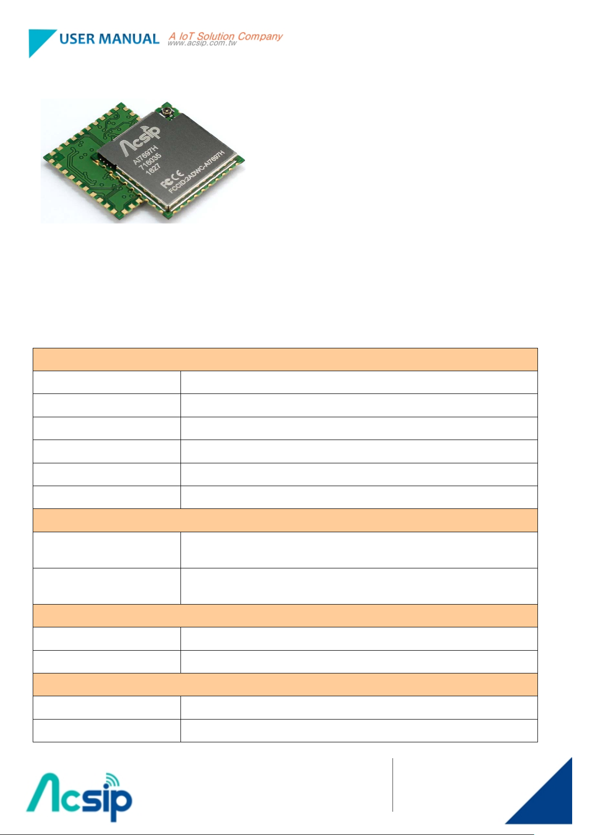
1. Description
AcSiP Technology Corp. introduces a low-cost and low-power consumption IoT module. This
stand-alone module is an operating system designed for wearable or internet of things (IoT) devices
with smart connection and cloud application/services.
AI7687H is a highly integrated SIP module which features an application processor, a low power 1x1
11n single-band Wi-Fi subsystem, a Bluetooth subsystem, and a Power Management Unit. The
application processor subsystem contains an ARM Cortex-M4F MCU, which has many peripherals,
including UART, I2C, SPI, I2S, PWM, IrDA, and auxiliary ADC. AI7687H also includes embedded
SRAM/ROM and a SPI 2MB serial flash.
Th e Wi -Fi subsystem contains the 802.11b/g/n radio, baseband, and MAC that are designed to meet
both the low power and high throughput application. It also contains a 32-bit RISC CPU that could
fully offload the application processor.
One I2S interface multiplexed with GPIO
1.1. Platform Features
General
ARM Cortex M4 MCU with FPU with up to
192MHz clock speed
352KB SRAM / 64KB boot / 2MB Flash
Supports external serial flash with Quad
Peripheral Interface (QPI) mode
Supports eXecute In Place (XIP) on flash
32KB cache in XIP mode
Hardware crypto engines including AES,
Four channel 12-bit ADC multiplexed with GPIO
Dedicated high-performance 32-bit RISC CPU N9
up to 160MHz clock speed
IEEE 802.11 b/g/n compliant
Supports 20MHz,40MHz bandwidth in 2.4GHz
Dual-band 1T1R mode with data rate up to
150Mbps
Supports STBC, LDPC
Greenfield, mixed mode, legacy modes support
IEEE 802.11 d/e/h/i/k/r/w support
DES/3DES, SHA2 for network security
Tw o UART interfaces with hardware flow control
and one UART for debug, all multiplexed with
GPIO
One SPI slave interface multiplexed with GPIO
Two I2C master interface multiplexed with GPIO
Security support for WFA WPA/WPA2 personal,
WPS2.0, WAPI
Supports 802.11w protected managed frames
QoS support of WFA WMM, WMM PS
Integrated LNA, PA, and T/R switch
Optional external LNA and PA support.
Vers ion
MT7687 IoT SiP Module
A
Date
FEB 21,2017
Page
1 of 9
Page 3
AI7687H
Product Name
RX diversity support with additional RX input
Operating : -20℃ ~ +70℃
2. Specification
AI7687H
Chipset MT7687
Core ARM Cortex-M4 MCU
FPU Clock Speed 192MHz
SRAM 352KB
SPI Flash 2MB
Antenna connector MHF4 series: 20449-001E
Operation Condition
Temperature
Humidity
Mechanical Information
Dimension 18mm X 18mm X 1.7mm (Typ.)
Storage : -40℃ ~ +85℃
Operating : 10 ~ 95% (Non-Condensing)
Storage : 5 ~ 95% (Non-Condensing)
Package LGA 44Pin – Stamp hole type
Certification
FCC ID 2ADWC-AI7687H
CE EN300328 / MPE / EN301489-1-17 / EN60950-1
Vers ion
Date
Page
MT7687 IoT SiP Module
A
FEB 21,2017
2 of 9
Page 4

AI7687H
Product Name
3. Pin Definition
Vers ion
MT7687 IoT SiP Module
A
Date
FEB 21,2017
Page
3 of 9
Page 5

AI7687H
Product Name
3.1. Detailed Pin Description
PIN no. Pin Name PIN no. Pin Name
1 GPIO29 23 GPIO0
2 GPIO30 24 GPIO1
3 GPIO28 25 GPIO2
4 GPIO27 26 GPIO3
5 PMU_EN_WF 27 GPIO6
6 GPIO60 28 GPIO7
7 GPIO59 29 GPIO5
8 GPIO58 30 GPIO24
9 GPIO57 31 GPIO25
10 GPIO39 32 GPIO26
11 SYS_RST_N 33 GPIO4
12 GPIO38 34 RTC_3V3
13 GPIO37 35 GND
14 3V3 36 PMU_EN_RTC
15 GPIO36 37 GPIO32
16 GPIO35 38 GPIO31
17 GPIO34 39 3V3
18 GPIO33 40 GND
19 GND 41 Thermal GND
20 NC 42 Thermal GND
21 GND 43 Thermal GND
22 GND 44 Thermal GND
Vers ion
Date
Page
MT7687 IoT SiP Module
A
FEB 21,2017
4 of 9
Page 6

AI7687H
Product Name
4. Operating Block
2.4GHz Antenna
Vers ion
Date
Page
MT7687 IoT SiP Module
A
FEB 21,2017
5 of 9
Page 7

AI7687H
Product Name
PuTTY Program
Vers ion
MT7687 IoT SiP Module
A
Date
FEB 21,2017
Page
6 of 9
Page 8

AI7687H
Product Name
Command
1. Software operating
Connect the board to PC with a serial port cable.
Build the example project and download the binary file to the MT7687.
Reboot the HDK, the console will show "FreeRTOS Running" message to indicate the HDK is booting up.
Use '?' and enter to query the available command line options.
Note that the command line options are still under development and subject to change without notice.
Below are two examples to demonstrate the Wi-Fi station and Wi-Fi access point modes of MT7687.
Example 1. Wi-Fi station mode.
Find your Wi-Fi access point settings:
Before connecting to a Wi-Fi access point, the following information needs to be collected:
1. What is the SSID of your Wi-Fi access point?
2. What is the authentication mode of your Wi-Fi access point?
In general, it is WPA PSK or WPA2 PSK. If you want to use different settings, please read
the table 'Table 1. Supported AuthMode(s)' at the bottom of this example.
3. What is the password of your Wi-Fi access point?
4. What is the encryption mode of your Wi-Fi access point?
In general, AES or TKIP is used. If you want to use different settings, please read th e table
'Table 2. Supported EncrypType(s)' at the bottom of this example.
Once you have this information, use the following commands to configure the HDK. This
example assumes you want to use either WPA PSK or WPA2 PSK,your packets are encrypted
Vers ion
MT7687 IoT SiP Module
A
Date
FEB 21,2017
Page
7 of 9
Page 9

AI7687H
Product Name
with TKIP or AES, the access point SSID is 'myhome' (length 6), and the password of WPA or
WPA2 is '12345678' (length 8).
config write STA AuthMode 9
config write STA EncrypType 8
config write STA Ssid myhome
config write STA SsidLen 6
config write STA WpaPsk 12345678
config write STA WpaPskLen 8
config write common OpMode 1
Press the reset button on the LinkIt 7687 HDK to restart the system.
Boot up with the new configuration.
If everything is correct, similar messages will be shown in the console to notify your HDK has
received an IP address.
************************
DHCP got IP:10.10.10.101
************************
PING from the LinkIt 7687 HDK (SDK v3.1.0)
If the IP address is fetched and the network is operating, the LinkIt 7687 can ping other
devices/computer on the network with the following command in the console.
f 11 10.10.10.254 3 64
2. Federal Communication Commission Interference Statement
This device complies with Part 15 of the FCC Rules. Operation is subject to the following two conditions:
(1) This device may not cause harmful interference, and (2) this device must accept any interference
received, including interference that may cause undesired operation.
This equipment has been tested and found to comply with the limits for a Class B digital device, pursuant
to Part 15 of the FCC Rules. These limits are designed to provide reasonable protection against
harmful interference in a residential installation. This equipment generates, uses and can radiate radio
frequency energy and, if not installed and used in accordance with the instructions, may cause harmful
interference to radio communications. However, there is no guarantee that interference will not occur in a
particular installation. If this equipment does cause harmful interference to radio or television reception,
which can be determined by turning the equipment off and on, the user is encouraged to tr y to correct the
interference by one of the following measures:
Reorient or relocate the receiving antenn a.
Vers ion
MT7687 IoT SiP Module
A
Date
FEB 21,2017
Page
8 of 9
Page 10

AI7687H
Product Name
Increase the separation between the equipment and receiver.
Connect the equipment into an outlet on a circuit different from that to which the receiver is connected.
Consult the dealer or an experienced radio/TV technician for help.
FCC Caution:
Any changes or modifications not expressly approved by the party responsible for compliance could void the user's
authority to operate this equipment.
This transmitter must not be co-located or operating in conjunction with any other antenna or transmitter.
Radiation Exposure Statement:
This equipment complies with FCC radiation exposure limits set forth for an uncontrolled environment.
This equipment should be installed and operated with minimum distance 20cm between the radiator &
your body.
This device is intended only for OEM integrators under the following conditions:
1)The antenna must be installed such that 20 cm is maintained between the antenna and users, and the
maximum antenna gain allowed for use with this device is 2 dBi.
2) The transmitter module may not be co-located with any other transmitter or antenna.
As long as 2 conditions above are met, further transmitter test will not be required. However, the OEM
integrator is still responsible for testing their end-product for any additional compliance requirements
required with this module installed.
IMPORTANT NOTE: In the event that these conditions can not be met (for example certain laptop
configurations or co-location with another transmitter), then the FCC authorization is no longer
considered valid and the FCC ID can not be used on the final product. In these circumstances, the OEM
integrator will be responsible for re-evaluating the end product (including the transmitter) and obtaining a
separate FCC authorization.
End Product Labeling
This transmitter module is authorized only for use in device where the antenna may be installed such that
20 cm may be maintained between the antenna and users. The final end product must be labeled in a
visible area with the following: “Contains FCC ID: 2ADWC-AI7687H ”. The grantee's FCC ID can be
used only when all FCC compliance requirements are met.
Manual Information To the End User
The OEM integrator has to be aware not to provide information to the end user regarding how to install
or remove this RF module in the user’s manual of the end product which integrates this module. The end
user manual shall include all required regulatory information/warning as show in this manual.
Vers ion
MT7687 IoT SiP Module
A
Date
FEB 21,2017
Page
9 of 9
 Loading...