

Page 1
AR-V5430FL Installation Guide
AR-V5430FL
Installation Guide
Revision Description Date
1.0 Release 2009/07/24
1/39
Page 2

AR-V5430FL Installation Guide
Contents
1. INTRODUCTION TO AR-V5430FL .............................. 3
1.1 Specifications.................................................................................. 3
1.2 What You Have............................................................................... 4
2. SYSTEM DISSECTIONS.............................................. 5
2.1 Dimensions ..................................................................................... 5
2.2 Front Panel “I/O” ............................................................................. 6
2.3 System Configuration ..................................................................... 7
3. PROCEDURE OF ASSEMBLY/DISASSEMBLY......... 9
3.1 2.5” Hard Disk Installation............................................................... 9
3.2 Accessory (SO-DIMM, CF Card, SIM Card, Outline bracket)
Installation
3.3 GPS/GPRS/WiFi Modules Installation .......................................... 19
..................................................................................... 15
4. APPENDIXES (OPTIONAL DEVICES)...................... 22
4.1 AR-PW0932V ............................................................................... 22
4.2 AR-B2011 GSM/GPRS Carrier Board with ACM8060 Module...... 27
4.3 ACC-V5430-GPS (ER-332-MCX90))............................................ 31
4.4 AR-B2012 GPIO Board................................................................. 35
4.5 Acrosser Wireless Networking WLAN (VNT6656G6A40)............. 38
2/39
Page 3
AR-V5430FL Installation Guide
1
AR-V5430FL is a Fan-less system product mainly for PC applications in the vehicle
industry. With a powerful Intel CPU core & diverse memory card extensions (CF card,
SO-DIM), AR-V5430FL can satisfy user requirements in any vehicle industry application
environment, especially in the field of vehicle computers. AR-V5430FL has a diverse
physical interface in the front panel, such as GPIO’s DB15, 2*(10/100/1000Base-T)
LANs, VGA/DVI connectors, build-in LEDs, 3 USB Ports, 2 COM ports, FUSE, ATX
Power Switch & Remote Switch/ Microphone/Speak, DC inlet. In addition, the system
provides the capacity for extending I/O devices by options adding GPS/GPRS/WiFi
depending on user’s needs.
INTRODUCTION TO AR-V5430FL
1.1 Specifications
Item Description
System AR-V5430FL
CPU Board AR-B5430 series
System Dimensions 279x176x67(mm)
3/39
Page 4
AR-V5430FL Installation Guide
1.2 What You Have
Description Quantity
AR-V5430FL 1
Terminal block (Plug) 1
Wall Mount Bracket(Including label for isolation ) 2
Compact Disk 1
SATA Power Cable 1
SATA Cable 1
KB/MS Y Cable 1
Remote Switch Cable 1
2.5”HDD Bracket (Screws-8PCS) 1
GPS External Cable (Option) 1
GPRS External Cable (Option) 1
WiFi External Cable (Option) 1
Fuse 7.5A for 24V vehicles 1
4/39
Page 5

AR-V5430FL Installation Guide
2
SYSTEM DISSECTIONS
2.1 Dimensions
z Golden Fingers, Main Chips and Standard connectors (Top Side)
5/39
Page 6
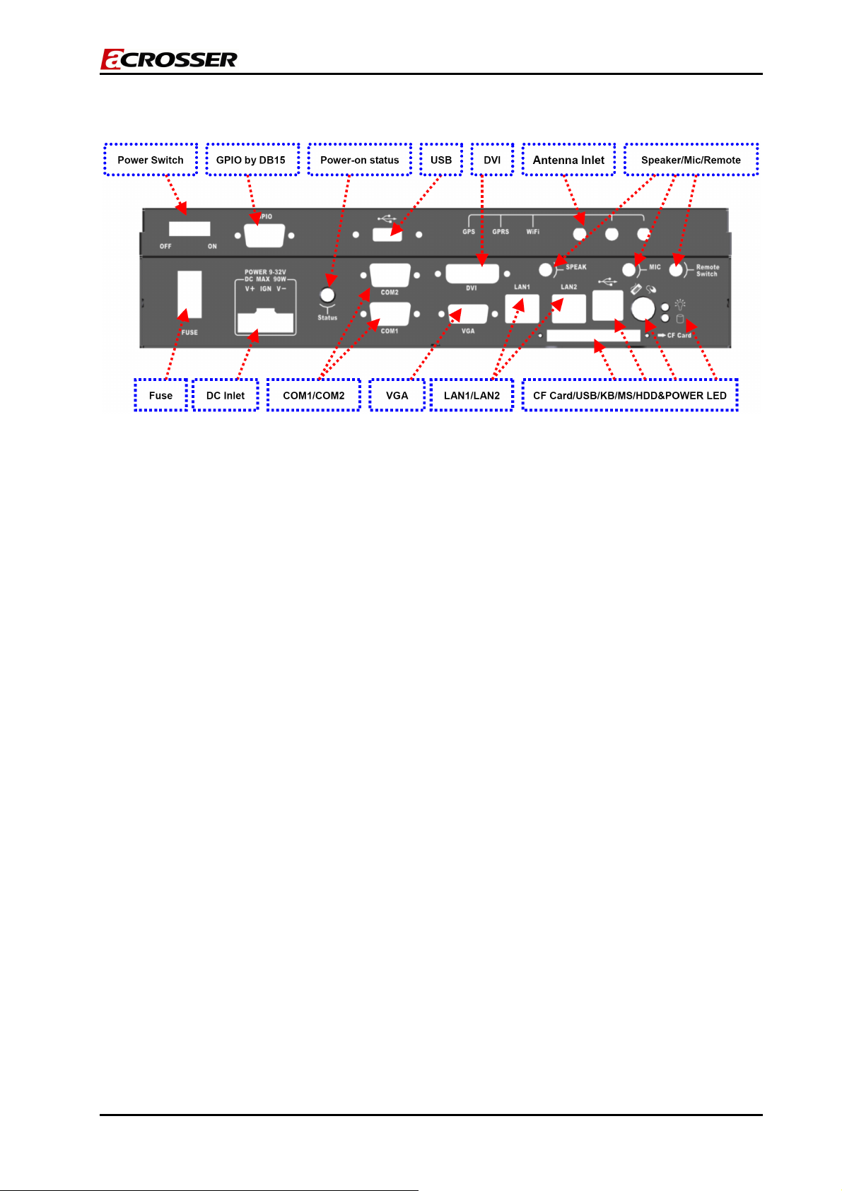
2.2 Front Panel “I/O”
;
AR-V5430FL Installation Guide
6/39
Page 7
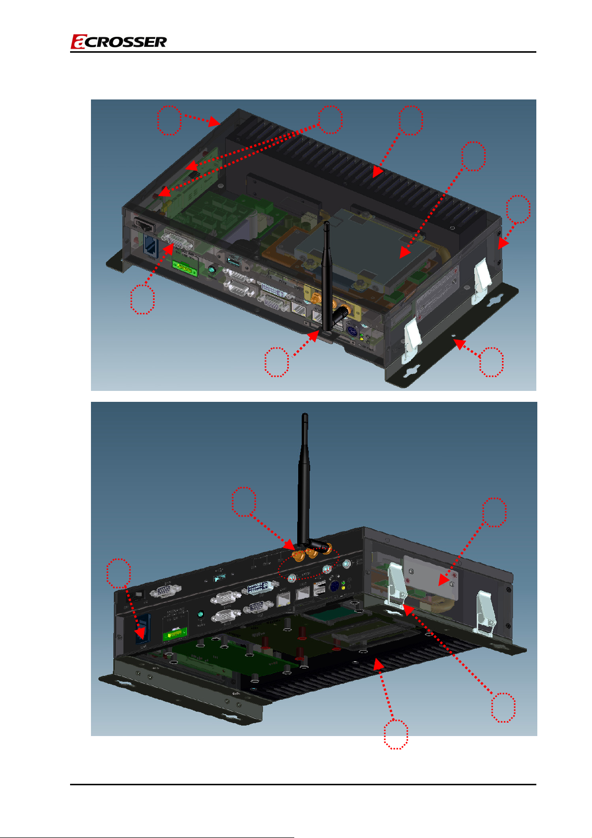
2.3 System Configuration
AR-V5430FL Installation Guide
1
8
3
7
2
6
5
4
13
12
10
9
11
7/39
Page 8
AR-V5430FL Installation Guide
Item Description Quantity
1 Upper Case 1
2 Bottom Case 1
3 Thermal Module 1
4 Mounting Bracket 2
5 CF Card Bracket 1
6 GPIO Board 1
7 HDD Module 1
8 GPS &GPRS Module 1
9 WiFi Module 1
10 DDRII Lid 1
11 Lock modules of bracket 4
12 GPS/GPRS/WiFi Antenna Inlet 1
13 Fuse 15A for 12V vehicles (default value) 1
8/39
Page 9
AR-V5430FL Installation Guide
PROCEDURE OF
3
ASSEMBLY/DISASSEMBLY
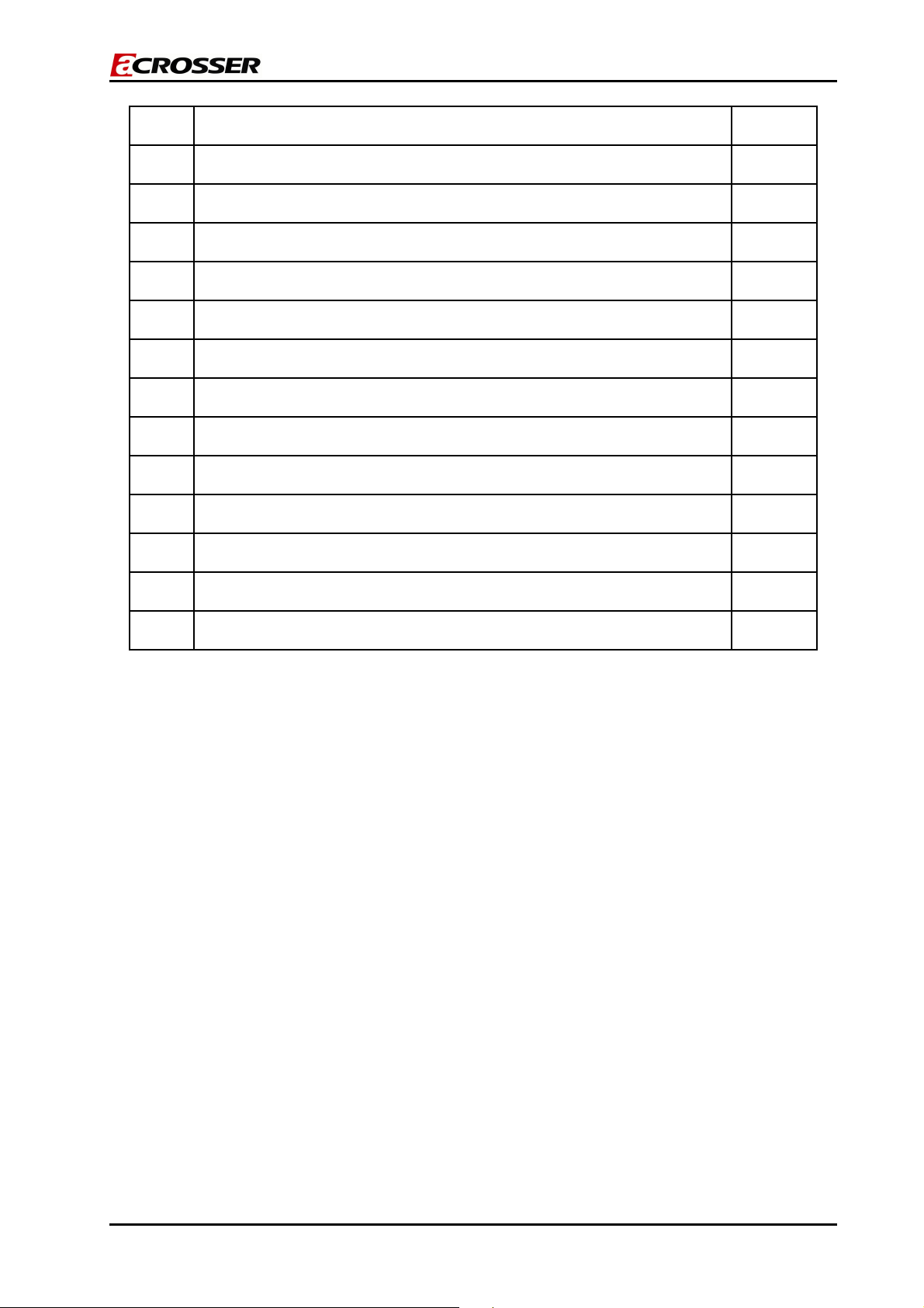
3.1 2.5” Hard Disk Installation
The following instructions will guide you step-by-step through the HDD installation.
1. Remove the terminal plug from AR-V5430FL.
2. Unfasten the screw from the top cover of AR-V5430FL.
Unfasten the screw!!
Remove the external power adapter!!
9/39
Page 10
AR-V5430FL Installation Guide
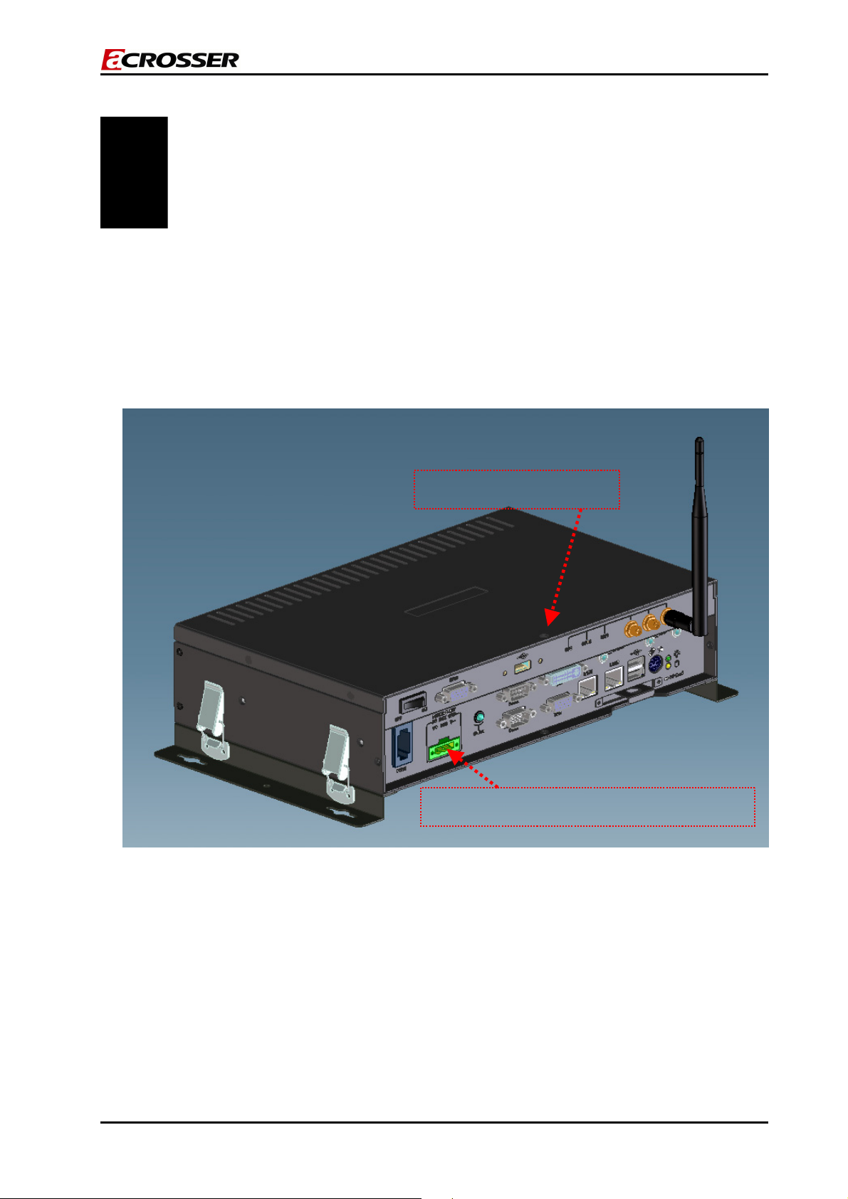
3. Remove the top cover in the direction shown on the photo below.
Remove
Push
Push
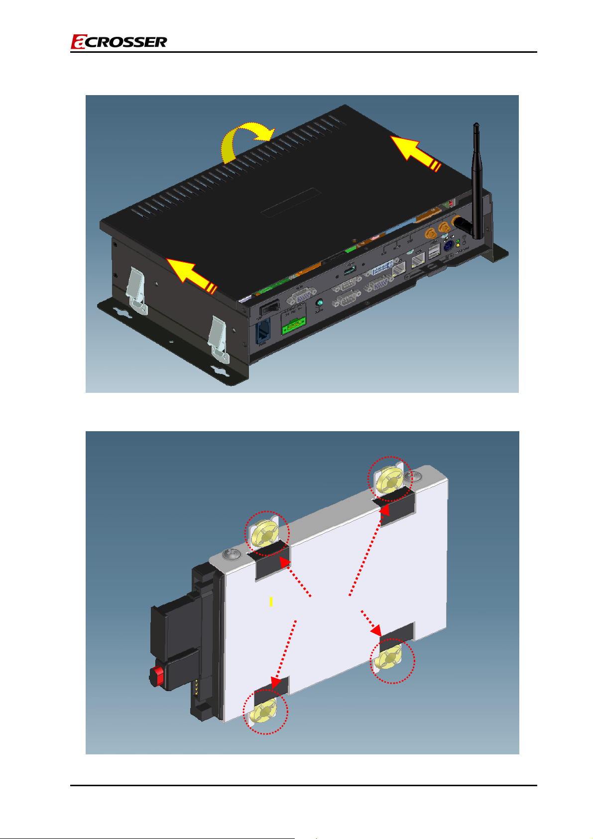
4. Attach the rubbers onto the HDD bracket.
Install the rubbers on the HDD bracket.
10/39
Page 11
AR-V5430FL Installation Guide
5.
Place HDD body into the HDD bracket and assemble the HDD and the bracket with 4 screws.
Screws up
6. Insert the SATA connecter and SATA power cable into the HDD module.
11/39
Page 12
AR-V5430FL Installation Guide
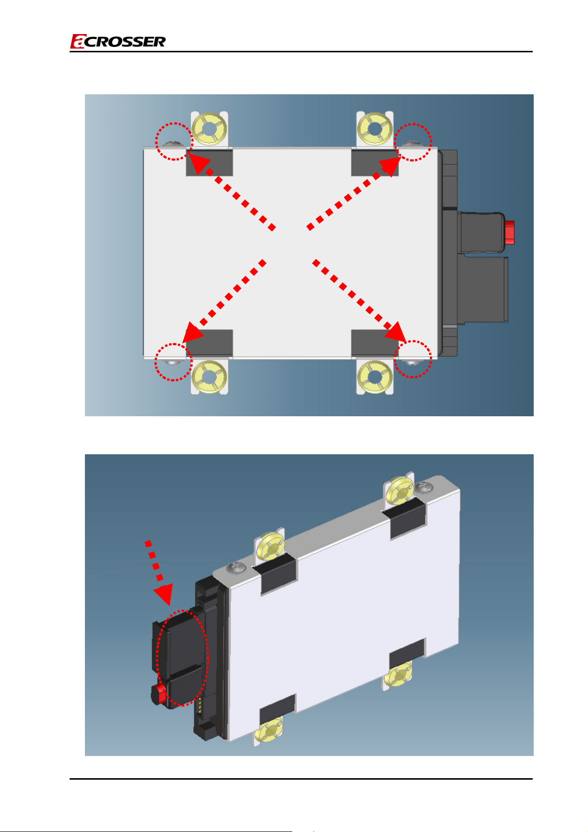
7. Assemble the HDD module and HDD bracket with 4 screws.
Screws up
8. Place the HDD module back into the case.
9. Fix the HDD module to the chassis using four screws.
Bracket installation for HDD
12/39
Page 13

AR-V5430FL Installation Guide
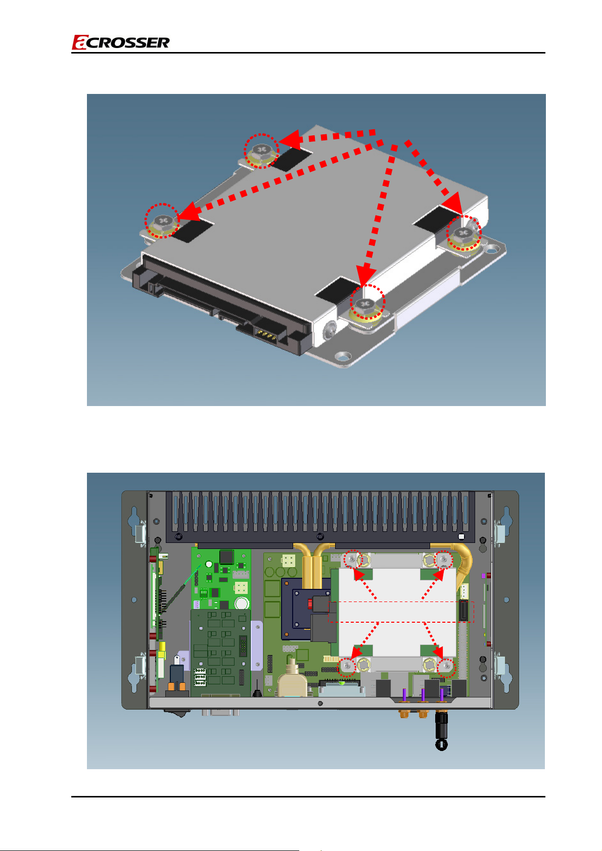
10. Plug the SATA cable and power cable into the mainboard.
SATA Power connector
11. Slide the top cover into the bottom chassis.
SATA Connecter
Pay attention to make sure that the top cover has been installed into the notch!
13/39
Page 14

12. Finish the HDD installation after fastening the screw.
Fasten the screw
Push
AR-V5430FL Installation Guide
Push
14/39
Page 15

AR-V5430FL Installation Guide
3.2 Accessory (SO-DIMM, CF Card, SIM Card, Outline
bracket) Installation
Install SO-DIMM
1. Remove the extension bracket by unfastening the screw.
Unfasten screw when installing the SO-DIMM card.
2. Install SO-DIMM following below instructions.
Push
Insert the SO-DIMM
Push
15/39
Page 16

AR-V5430FL Installation Guide
Install CF Card
1. Remove the extension CF bracket by unfastening the screws.
2. Install the CF card into the bracket.
Unfasten the screws
The direction for installing the CF card.
16/39
Page 17

3. Install the CF card module back into CF socket.
AR-V5430FL Installation Guide
Install SIM Card
1. Install the SIM card into the SIM socket.
Direction for installing the CF card module.
17/39
Page 18

AR-V5430FL Installation Guide
Install Outline Bracket
1. Install the fasteners on the case using 4 screws.
2. Install the other side of fasteners on the Outline bracket using 4 screws.
3. Lock the fasteners.
18/39
Page 19

AR-V5430FL Installation Guide
3.3 GPS/GPRS/WiFi Modules Installation
1. Unfasten the 2 screws to release GPS/GPRS brackets.
Unfasten the screws.
2. After GPS/GPRS bracket release, please install GPS/GPRS onto the bracket by
fastening 4 screws.
19/39
Page 20

AR-V5430FL Installation Guide
3. Install GPS/GPRS modules into the chassis by fastening 2 screws as in step 1.
4. Unfasten the 2 screws to release WiFi bracket.
Unfasten the screws.
5. After WiFi bracket release, please install WiFi onto the bracket by fastening 2 screws.
20/39
Page 21

AR-V5430FL Installation Guide
6. Install Wifi modules into the chassis by fastening 2 screws as in step 4.
Please do not change the CPU by yourself. Any disassembly and assembly of the the
CPU thermal module will cause unexpected damage.
Please contact the Acrosser customer service center/FAE for changing the
CPU.
Please DO NOT disassemble and assemble the
thermal module by yourself
21/39
Page 22

AR-V5430FL Installation Guide
4
APPENDIXES (OPTIONAL DEVICES)
4.1 AR-PW0932V
Locations (Top Side)
PWR1
1
DC Power Input
FUSE1
2
Connect to fuse default 15A
J4
3
Front Panel connector
PWR3
4
Suspend Power for ATX function
CN1
5
Power button output
CN2
6
Reserve Pin
7
8
9
10
11
12
SW1
DIP switch for mode select.
JP2
Define KEY_SW, ENG_STS input
type
J5
Microchip programming connector
PWR4
12V(Max 2A), 5V(Max 2A) output
PWR2
Main +12V(Max 8A) output
COM1
Simple UART connector
22/39
Page 23

Connectors and Jumper Setting
PWR1
DC Power Input
FUSE1
Connect to fuse default 15A
AR-V5430FL Installation Guide
PIN SIGNAL
1 DC_IN
2 Key switch
3 GND
PIN SIGNAL
1,2 Fuse Out
3,4 Fuse In
J4
Front Panel connector
For detailed functions, please refer to the User
Manual.
PWR3
Suspend Power for ATX function
CN1
Power button output
CN2
Reserve Pin
SW1
DIP switch for mode select.
PIN SIGNAL PIN SIGNAL
1
PWRBTN_IN 2 GND
3
LOC_SW 4 GND
5
KEY_SW 6 GND
7
ENG_STS 8 GND
9
STS_LED 10 GND
PIN SIGNAL
1 GND
2 PS_ON
3 5V_SUS
PIN SIGNAL
1 PWBTN out
2 GND
PIN SIGNAL
1 PWBTN out
2 GND
Mode 1 2 3 4
0 ON ON ON ON
1 ON ON ON OFF
2 ON ON OFF ON
3 ON ON OFF OFF
4 ON OFF ON ON
5 ON OFF ON OFF
6 ON OFF OFF ON
7 ON OFF OFF OFF
23/39
Page 24

JP2
Define KEY_SW, ENG_STS input type
J5
Microchip programming connector
PWR4
12V(Max 2A), 5V(Max 2A) output
PWR2
Main +12V(Max 8A) output
AR-V5430FL Installation Guide
STATUS SETTING
Open High_active
Short Low_active
Reserve
PIN SIGNAL
1 +12V
2 GND
3 GND
4 +5V
PIN SIGNAL
1,2 GND
3,4 +12V
COM1
Simple UART connector
PIN SIGNAL
1 RX
2 Tx
3 GND
NOTE1: (For detailed functions, please refer to the User Manual.)
PWRBTN_IN: Trigger power-up at Mode0, Mode5, Mode6, Mode7
LOC_SW: Main system on/off switch
1. Short: System off
2. Open: System on (default)
KEY_SW: Trigger power-up at Mode2, Mode3, Mode4
ENG_STS: Detect the status of the main system.
STS_LED: Indicate power status.
Note2: (For detailed functions, please refer to the User Manual.)
Mode0: ATX function
Mode1: AT function
Mode2, Mode3, Mode4: Smart ATX (power-on by trigger KEY_SW)
Mode5, Mode6, Mode7: Smart ATX (power-on by trigger PWRBTN_IN)
24/39
Page 25

AR-V5430FL Installation Guide
Spec
Input DC 9V~32V, Output DC 12V (main) / 5V / 5VSB, Total 90W.
Definition
A. Soft-Off Delay: The period of time from the vehicle ignition or switch being turned
off until the power off signal is generated. The delay period is programmable.
B. Soft-Off Cycle: The period of time from the
power off signal being generated until
the system is off. There is only 5VSB (5V Standby) present when the system is off
(allows you to turn it on again when the vehicle is restarted)
C. Hard Off Delay: The period of time from the system being off until the 5VSB is
completely removed.
D. Hard Off Cycle: The period of time after the Hard Off Delay. The hard off cycle
completely removes the 5VSB power so that it does not drain the battery.
Mode
Mode
Soft OFF
Delay
Hard OFF
Delay
Power ON
Control
Power OFF
Control
0 (ATX) No No Remote Switch Remote Switch
1(AT) No No Local Switch Local Switch
2 5 seconds 1 minute Ignition Ignition /Remote
3 1 minute 5 minutes Ignition Ignition /Remote
4 30 minutes 2 hours Ignition Ignition /Remote
5 5 seconds 1 minute Remote Switch Ignition /Remote
6 1 minute 5 minutes Remote Switch Ignition /Remote
7 30 minutes 2 hours Remote Switch Ignition /Remote
Special function (only supported on modes 2~7)
A. Power on retry: If the motherboard cannot be turned on normally, the
AR-PW0932V will send an “ON” pulse to the motherboard again. The
AR-PW0932V will re-try this procedure 3 times. If the motherboard still cannot be
turned on normally after 3 retries, the AR-PW0932V will turn off 5VSB and stay in
the hard off state. The status LED will display an error code (5 flashes). The
power module will keep in the state until the ignition is turned off.
B. The AR-PW0932V sends an “ON” pulse to the motherboard when the ignition is
on for more than 2 seconds.
C. The AR-PW0932V will ignore the status change of the ignition after the ON pulse
is sent to the motherboard for 3 minutes. After this period, the AR-PW0932V will
start to check its status. This can avoid an improper “OFF” process before the OS
is completely booted.
D. The AR-PW0932V will ignore the status change of the ignition and the remote
switch during the time the “OFF” pulse is sent out. This will avoid an improper ON
process before the motherboard is completely shut down.
E. Power off retry: If the motherboard cannot be shut down normally (/PSON does
25/39
Page 26

AR-V5430FL Installation Guide
not go to high) within 3 minutes after “OFF” pulse is sent, the AR-PW0932V will
send the off pulse to the motherboard again. If the motherboard still cannot be
shut down normally, the power output will be turned off directly.
F. If the ignition turns back to “ON” during the “OFF” Delay, the AR-PW0932V will
stay in operation. The “OFF” signal will not be sent to the motherboard. The
“OFF” Delay will re-start the next time when the ignition is off.
G. Power input monitoring: The AR-PW0932V will constantly monitor the input
voltage. If the input voltage is below 11.2 Volts (the standard might have 5%
tolerance), the AR-PW0932V will not start the power on procedure. When
AR-PW0932V has ran into operation and the battery drops below 10.8 Volts
(with 5% tolerance) for more than 10 seconds, the AR-PW0932V will shut down
the motherboard following the standard shut down procedure. If the input voltage
recovers within 10 seconds to a level of more than 10.8 Volts (with 5% tolerance)
again, the AR-PW0932V will continue to run. (Figure 4) If this happens, the
ignition shall be off and on again (Mode 2, 3, 4) or press the remote switch (Mode
5,6,7) if you want to turn on the system again.
LED flashing
A. Mode 0 and 1: The LED will be constantly ON when the power output is ON. The
LED will be constantly OFF when the power output is off.
B. Mode 2 to 7 (Smart ATX mode):
The LED will flash a number of times to indicate the status. Each blink remains 500
milliseconds ON followed by a 500 ms OFF. Each Cycle will have a 5-second OFF in
between.
LED flashing number Status
0 (constant ON) Power Output runs normally
1 Hard off mode
2
Standby mode (After power output is turned
off until 5VSB is turned off)
Power soft off delay. (After the ignition is
3
turned off or the remote switch is pressed
until power output is turned off.)
4 Battery voltage low
5
System on/off fail. When the motherboard
cannot turn on or turn off after retry.
6-128 Reserved
26/39
Page 27

AR-V5430FL Installation Guide
4.2 AR-B2011 GSM/GPRS Carrier Board with ACM8060
Module
Location (Top Side)
Location (Bottom Side)
27/39
Page 28

JP1
1
5V TO RS232 & RESET & POWER LED
JP2
2
PIN HEADER FOR AUDIO IN/OUT
CN1
3
12V & 5V POWER INPUT
CN2
4
PIN HEADER FOR RS-232 SIGNALS
CN3
5
SIM CARD SOCKET
CON1
6
GSM/GPRS MODULE BOARD TO BOARD CONNECTOR
Connectors and Jumper Setting
JP1
5V TO RS232 & RESET & POWER
LED
JP2
PIN HEADER FOR AUDIO IN/OUT
AR-V5430FL Installation Guide
PIN DEFINE
1-2 RED LED
3-4 GREEN LED
SELECT RS232
5-6
PIN 10 WITH +5V
7-8 GND
PIN SIGNAL PIN SIGNAL
1
LINE_X_R 2 LINE_X_L
3
AUDIO_GND 4 AUDIO_GND
5
MIC_IN 6 AUDIO_GND
CN1
12V & 5V POWER INPUT
CN2
PIN HEADER FOR RS-232 SIGNALS
PIN SIGNAL
1 +12V
2 GND
3 GND
4 +5V
PIN SIGNAL PIN SIGNAL
1 DCD 2 DSR
3 RXD 4 RTS
5 TXD 6 CTS
7 DTR 8 RI
9 GND 10 5PWR
28/39
Page 29

CN3
SIM CARD SOCKET
CON1
GSM/GPRS MODULE BOARD TO
BOARD CONNECTOR
AR-V5430FL Installation Guide
PIN SIGNAL PIN SIGNAL
1 SIM_VCC 2 SIMRSCDn
3 SIMCKCDn 4 GND
5 X 6 SIMIOCDn
PIN SIGNAL PIN SIGNAL PIN SIGNAL PIN SIGNAL PIN SIGNAL
1 SIMCKCDn 11 X 21 GND 31 VDD_TOP 41 ON_KEY
2 SIM_VCC 12 X 22 GND 32 RI0 42 AUDIO_GND
3 SIMIOCDn 13 LPG_RED 23 GND 33 DTR0 43 MICP
4 SIMRSCDn 14 X 24 GND 34 CTS0 44 MICN
5 LPG_GREEN 15 TX0 25 GND 35 DSR0 45 X
6 GND 16 X 26 +4V 36 X 46 X
7 X 17 RX0 27 +4V 37 RTS0 47 X
8 X 18 X 28 +4V 38 X 48 X
9 X 19 X 29 +4V 39 DCD0 49 EARP
10 X 20 X 30 +4V 40 X 50 EARN
Features
Quad-Band GSM 850/900/1800/1900 MHz
GPRS Multi-Slot Class 10
Compliant to GSM phase 2/2+
Output power:
- Class 4 (2 W) for EGSM850
- Class 4 (2 W) for EGSM900
- Class 1 (1 W) for GSM1800
- Class 1 (1 W) for GSM1900
Control via AT commands
(Hayes 3GPP TS 27.007, TS 27.005)
TCP/IP stack access via AT commands
Internet Services: TCP, UDP
Supply voltage range: 3.4V~ 4.5 V
Power consumption
- Power down 60uA
- Sleep mode 3.0 mA
- Speech mode (average) 260 mA
- GPRS class 10 (average) 350 mA
Temperature range
- Normal Operation: -30°C to +85°C
29/39
Page 30

AR-V5430FL Installation Guide
- Storage: -40°C to +85°C
CSD data transmissions
- Up to 9600 bps
- V.110
- Non-transparent mode
- USSD support
SMS
- Point-to-point MO and MT
- SMS cell broadcast
- Text and PDU mode
- Extended Message (EMS)
Fax
- Group 3, Class 1
Voice
- Triple-rate codec for HR, FR, and EFR
- Adaptive multi-rate AMR
- Basic hands-free operation
- Echo cancellation
- Noise reduction
GPRS data transmission
- GPRS class 10: max. 86 kbps (DL)
- Mobile station Class B
- PBCCH support
- Coding schemes CS 1-4
Software User Guides (Click the following link to read the file)
AMOD GSM Module AT Commands reference manual_en V1.6.pdf
AMOD GSM_GPRS Enhanced AT Command V1.4.pdf
GSM_GPRS Software Development Guide_ENG V1.4.pdf
30/39
Page 31

AR-V5430FL Installation Guide
4.3 ACC-V5430-GPS (ER-332-MCX90))
Features
SiRF StarⅢ high-performance GPS Chip Set
Very high sensitivity (Tracking Sensitivity: -159 dBm)
Extremely fast TTFF (Time To First Fix) at low signal level
Compact size (40.5mm * 35 mm * 10mm) suitable for space-sensitive application
Support NMEA 0183 and SiRF binary protocol
Build-in Super-Cap to reserve system data for rapid satellite acquisition.
Cold start under 40 seconds, average
Hot start under 1 seconds, average
Specification
General
Chipset
Frequency L1, 1575.42 MHz
C/A code 1.023 MHz chip rate
Channels 20 channel all-in-view tracking
Sensitivity -159 dBm
Accuracy
Position
Velocity 0.1 m/s
Time 1us synchronized to GPS time
Datum
Default WGS-84
SiRF StarⅢ
10 meters, 2D RMS
5 meters, 2D RMS, WAAS enabled
31/39
Page 32

Acquisition Time
Reacquisition 0.1 sec., average
Hot start 1 sec., average
Warm start 38 sec., average
Cold start 42 sec., average
Dynamic Conditions
Altitude 18,000 meters (60,000 feet) max
Velocity 515 meters/second (1000 knots) max
Acceleration Less than 4g
Jerk 20m/sec **3
Power
Main power input 3.8V ~ 6.5V DC input
Power
consumption
60mA (Continuous mode)
40mA (Trickle power mode)
Interface
Baud rate 4,800 to 57,600 bps adjustable
Output message SiRF binary or
NMEA 0183 GGA, GSA, GSV, RMC, VTG, GLL
Environmental
Operating Temp -40°C to +85°C
AR-V5430FL Installation Guide
32/39
Page 33

Physical Characteristics
AR-V5430FL Installation Guide
Inaccuracy: ±0.2mm
Interface Connection
* Pin-out of the 12-pin interface connector
Pin Name Description Type
1 GND Ground
2 VBAT Backup Battery Input
3 VDC 3.8V~5.5V DC Power Input Input
4 PBRES Push Button Reset Input (Active Low) Input
5 GPIO1 (Reserved)
6 TXA Serial Data Output A (GPS Data) Output
7 RXA Serial Data Input A (Command) Input
8 GND Ground
9 GND Ground
10 SELECT (Reserved)
33/39
Page 34

AR-V5430FL Installation Guide
11 TIMEMARK 1PPS Time Mark Output Output
12 GND Ground
Interface Description
* VDC (DC power input):
This is the main DC supply for a 3.8V ~ 5.5V power module board.
* VBAT (Backup battery):
This is the battery backup input that powers the SRAM and RTC when the main power is
removed. The typical current draw is 10uA. Without an external backup battery, the
module/engine board will execute a cold start after every start. To achieve the faster
start-up offered by a hot or warm start, a battery backup must be connected. To
maximize battery lifetime, the battery voltage should be between 2.5V and 3.6V.
* PBRES (Push button reset):
This pin provides an active-low reset input to the engine board. It causes the engine
board to reset and start searching for satellites.
* SELECT:
Do not connect.
* TXA:
This is the main transmits channel for outputting navigation and measurement data to
the user’s navigation software or user written software.
Output RS-232 level
* RXA:
Normally this pin must be kept in high, and if you don’t use this pin please connect a
resistor to pull high.
* Time mark:
This pin provides one pulse-per-second output from the engine board that is
synchronized with the GPS time.
* GND:
GND provides the ground for the engine board. Connect all grounds.
Software User Guide (Click the following link to read the file)
ER-332_MCX 90_ Software User Manual.pdf
34/39
Page 35

4.4 AR-B2012 GPIO Board
Location (Top Side)
AR-V5430FL Installation Guide
GPIO1
1
TO AR-B5430 GPIO
J1
2
JUMPER SELECT
CN2
3
DB15 MALE OUTPUT SIGNALS
CN3
4
POWER FORM AR-PW0932V
CN4
5
POWER TO GPRS/GSM (AR-B2011)
CN1
6
POWER TO GPS (Global-Sat ET-332 module)
35/39
Page 36

Connectors and Jumper Setting
GPIO1
TO AR-B5430 GPIO
J1
JUMPER SELECT
CN2
DB15 MALE OUTPUT SIGNALS
AR-V5430FL Installation Guide
PIN
1
3
5
7
9
DEFINE
GPI0 2 +5V
GPI1 4 GPI7
GPI2 6 GPI6
GPI3 8 GPI5
GND 10 GPI4
PIN
DEFINE
PIN DEFINE
1-2 NC (DEFAULT)
3-4 NO
5-6 GND (DEFAULT)
7-8 +5V
9-10 +12V
11-12 +EXT
PIN DEFINE
1 GPO1
2 GPO2
3 GPO3
4 GPO7
5 +5V
6 GND
7 GND
8 GND
9 +EXT
10 +EXT
11 GPO4
12 GPO0
13 GPO5
14 GPO6
15 +12V
CN3
POWER FORM AR-PW0932V
PIN DEFINE
1 +12V
2 GND
3 GND
4 +5V
CN4
POWER TO GPRS/GSM (AR-B2011)
PIN DEFINE
1 +12V
2 GND
3 GND
4 +5V
36/39
Page 37

AR-V5430FL Installation Guide
CN1
POWER TO GPS (Global-Sat ET-332
module)
PIN DEFINE
1 +12V
2 GND
3 GND
4 +5V
AR-B2012 GPIO board Software API Guide
InitGPIO( )
This function is used to set GPIO pin function. You have to call this function before
doing any GPIO actions. This function has no return value.
SetLevel(unsigned char pin, enum _level level)
This function is used to set GPO pin output level. Please refer to Appendix A for the
definition of GPO pin.
Return value:
0: Success
1: Fail
GetLevel(unsigned char pin, enum _level *level)
This function is used to get GPI pin output level. Please refer to Appendix A for the
definition of GPI pin.
Return value:
0: Success
1: Fail
Appendix A:
Input pin: 0,1,2,3
Output pin: 4,5,6,7
37/39
Page 38

AR-V5430FL Installation Guide
4.5 Acrosser Wireless Networking WLAN (VNT6656G6A40)
Description
The Acrosser Networking WLAN embedded system/IA solution is the innovative design
of VNT’s wireless chipset. The WLAN module is fully compliant with IEEE’s security and
802.11g standards. Enabling data rates between wireless devices of up to 54Mbps, it
can deliver the bandwidth necessary for real-time streaming of high-definition digital
multimedia content in home networks, and provide high-speed email, Web and LAN
access to multiple mobile users in corporate environments or public hotspots.
Radio
Frequency Band
Operating Channel
Modulation Type
Data Rate
Antenna
Radiation Power
Voltage Supply
Power Consumption
Receiver Sensitivity
Compliant
2400-2483.5MHz
IEEE 802.1b, Direct Sequence
Spread Spectrum, IEEE 802.11g,
Orthogonal Frequency Division
Multiplexing 13 Channels
QPSK, BPSK, CCK, OFDM
Up to 54Mbps
To support two external antennas via
connector
13-17dBm at maximum radiation direction
5V
384 uA@5V, Suspend/high speed mode
259 mA@5V, Active/high speed mode
Min -71dBm@54Mbps, PER<8%
Min -84dBm@11Mbps, PER<8%
FCC Part 15 C
CE ETSI 300-328
USB-IF
38/39
Page 39

Media Access Controller/ Baseband Controller
Chip
VT6656
AR-V5430FL Installation Guide
Media Access Protocol
CSMA/CA (Collision Avoidance) with ACK
General
USB Interface
Operating System
Supports USB2.0/1.1 Standard
Windows: 98SE/Me/NT/2000/XP/2003 Ser.,
Linux (2.6.x), CE (4.2/5.0b)
Physical Dimension
Weight
Operating Temp.
Storage Temp.
Operating Humidity
60x25x5.52mm (L×W×H)
10g
0~55°C
-20~70°C
0% to 70% while Operating
0% to 95% Non-condensing while Storage
Software User Guides (Click the following link to read the file)
vnt6655_6656_series model user manual _v1 5.pdf
vt6655_vt6656 Linux user guide.pdf
39/39
 Loading...