

Page 1

AR-R6006
System Guide
1
Page 2

Copyright
All Rights Reserved.
Manual’s first edition:
For the purpose of improving reliability, design and function, the information in this
document is subject to change without prior notice and does not represent a commitment on the
part of the manufacturer.
In no event will the manufacturer be liable for direct, indirect, special, incidental, or
consequential damages arising out of the use or inability to use the product or documentation,
even if advised of the possibility of such damages.
This document contains proprietary information protected by copyright. All rights are
reserved. No part of this Manual may be reproduced by any mechanical, electronic, or other
means in any form without prior written permission of the manufacturer.
Trademarks
AR-B6006、AR-R6006 are registered trademarks of Acrosser; IBM PC is a registered
trademark of the International Business Machines Corporation; Atom™ is a registered
trademark of Intel Technologies Inc; Phoenix is a registered trademark of Phoenix Software
International Inc; other product names mentioned herein are used for identification purposes
only and may be trademarks and/or registered trademarks of their respective companies.
2
Page 3

Table of Contents
1. 5 Introduction to AR-R6006................................................................................
1.1 ……………………………………………………….…………..5 Specifications
1.2 ...............................................................................................5 Packing List
1.3 ....................................................................................6 System Dissection
2. …………………………………………...8 Procedure of Assembly/Disassembly
2.1. ........................................................................................8 HDD Installation
2.2. ................................................................................12 CF Card Installation
2.3. .....................................................................13 Installing SO-DIMM DRAM
2.4. .......................................................................13 Rack Bracket Installation
3. 15 AR-B6006 Board Guide…………………………………………………………...
3.1. .15 Introduction………………………………………………………….
………..
3.1.1. ............................................................................................15 Features
3.1.2. .....................................................................................16 Specification
3.1.3. ............................................................................17 Package Contents
3.1.4. ..................................................................................18 Block Diagram
3.2. .............................................................................19 Hardware Information
3.2.1. ......................19 Locations of IO ports & Jumper settings definition
3.3. ............................................................................................25 BIOS Setting
3.3.1. ..................................................................25 Main (System Overview)
3.3.2. ......................................................25 Advanced (Advanced Settings)
3.3.3. ....................................................................................................26 Intel
3.3.4. .............................................................................................26 Security
3.3.5. ........................................................................................27 HWMonitor
3.3.6. .................................................................................................27 Power
3.3.7. ...........................................................................28 Boot(Boot Setting)
3.3.8. .....................................................................................................28 Exit
3
Page 4

Appendix............................................................................................................ 29
Appendix A - Driver Installation and Programming Guide (Windows).........29
A-1 GPIO and Watchdog................................................................................29
A-2 API List and Descriptions..………………………………………………….30
Appendix B - Programming Guide (Linux) ..................................................... 34
B-1 GPIO and Watchdog................................................................................34
B-2 API List and Descriptions……………………………………………………34
4
Page 5
1. Introduction to AR-R6006
Acrosser's Rackmount Networking device AR-R6006 is a cost-effective and entry-level solution,
which is suitable for small office. Base on Intel ATOM D525 (dual cores & 1M cache) 1.8GHz
CPU, the AR-R6006 consumes very low power to save the total costs. We also put a quiet fan
to keep the low noise, which will not cause uncomfortable voice. By Six 10/100/1000Mbps LANs,
the AR-R6006 is suff icient for the small business security hardware solution.
Key features:
1. Intel® Atom™ processor D525 (1M Cache, 1.8 GHz)
2. Intel ICH8M Chipset
3. 204-pin DDR3 SO-DIMM socket x 2 , DDR3 up to 4GB
4. Intel 82574L 10/100/1000Mbps x 6
5. Support two pairs LAN bypass feature
6. CF socket, 2.5”/3.5” Disk bay x 1, SATA II interface with power x 3
7. Console, VGA (pin header), USB 2.0 x 4 (2 x connectors, 2 x pin header)
8. Support console redirection
9. Support mini-PCI for feature expansion
1.1 Specifications
Item Description
System AR-R6006
CPU Board AR-B6006
System Dimension 430 mm x 44 mm x 320 mm (W x H x D)
1.2 Packing List
Description Q’ty
AR-R6006 System
1
Driver CD 1 Quick User Manual 1 Console Cable (P/N:190030627-G) 1 VGA Cable 1 Screw for bracket (for Rack + HDD bracket) 1 Rack bracket with Screw x 3 2 USA or Europe or Japan or UK power cord 1
5
Page 6
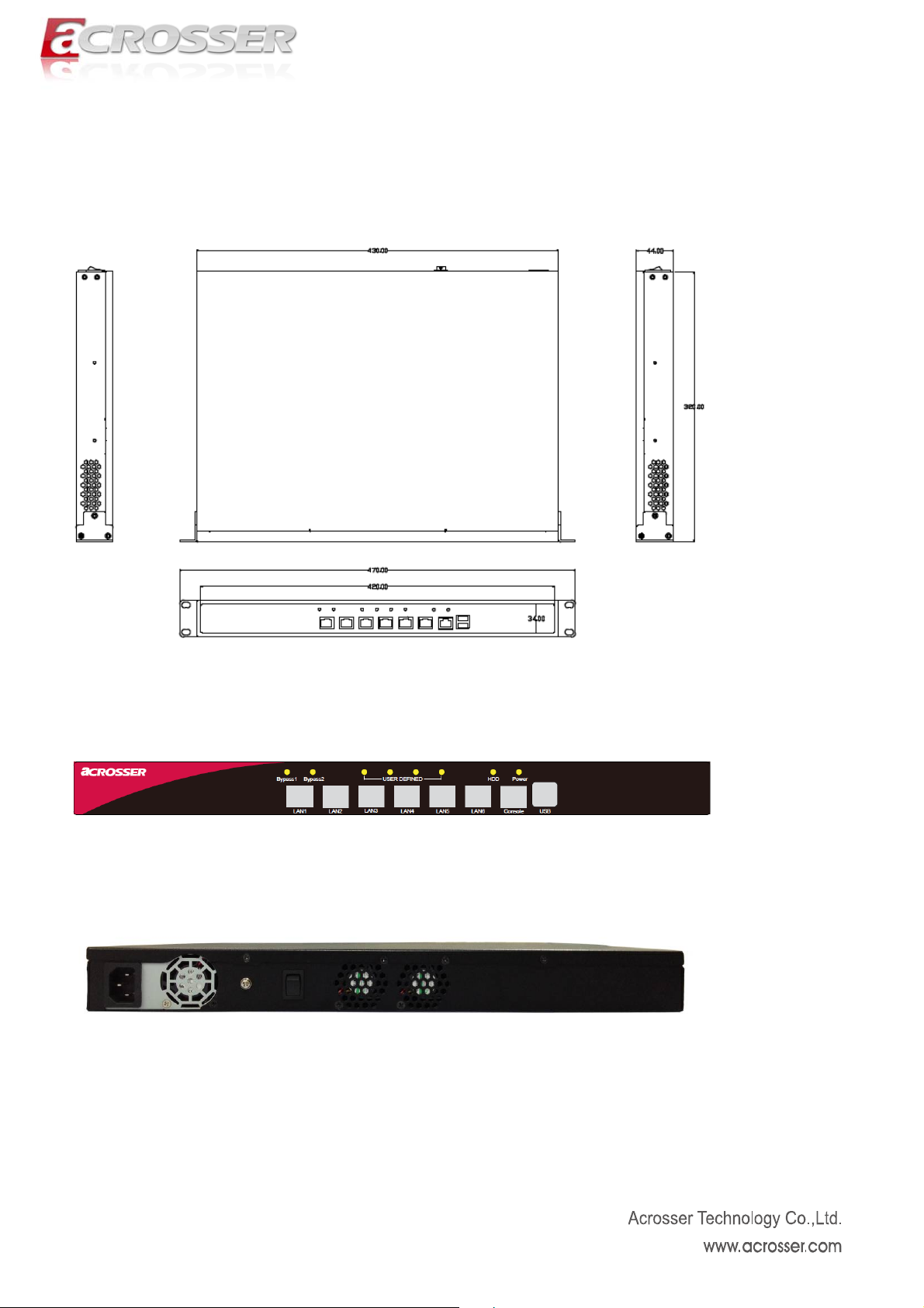
1.3 System Dissection
(1) Dimensions
(2) Front Panel
(3) Back Panel
6
Page 7
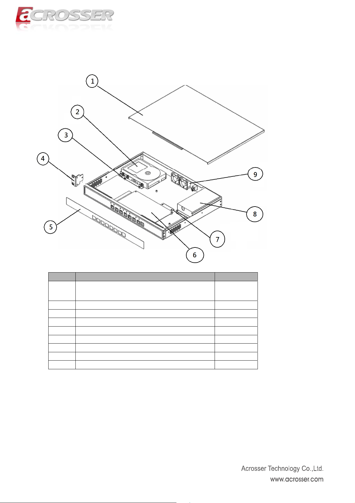
(4) System Configuration
Item Description Quantity
1
Top Cover 1
2 Disk Bracket 1
3 Bottom Base 1
4 1U Ear Bracket 1
5 Membrane 1
6 AR-B6006 Mainboard 1
7 CF Card Bracket 1
8 Power Supply 1
9 System FAN 2
7
Page 8
2. Procedure of Assembly/Disassembly
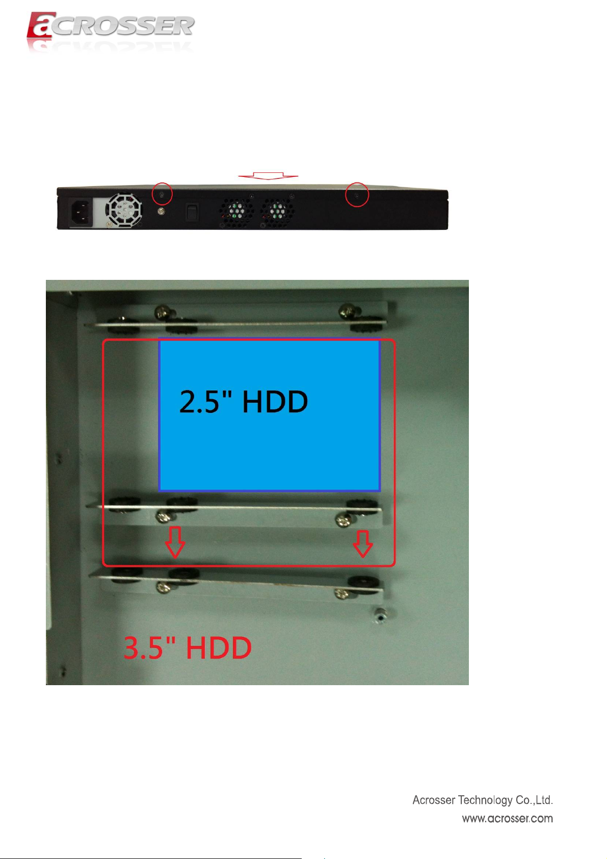
2.1. HDD Installation
The following instructions will guide you to install 2.5” HDD step-by-step.
1. Unfasten 2 screws of chassis top cover and take off it.
8
Page 9
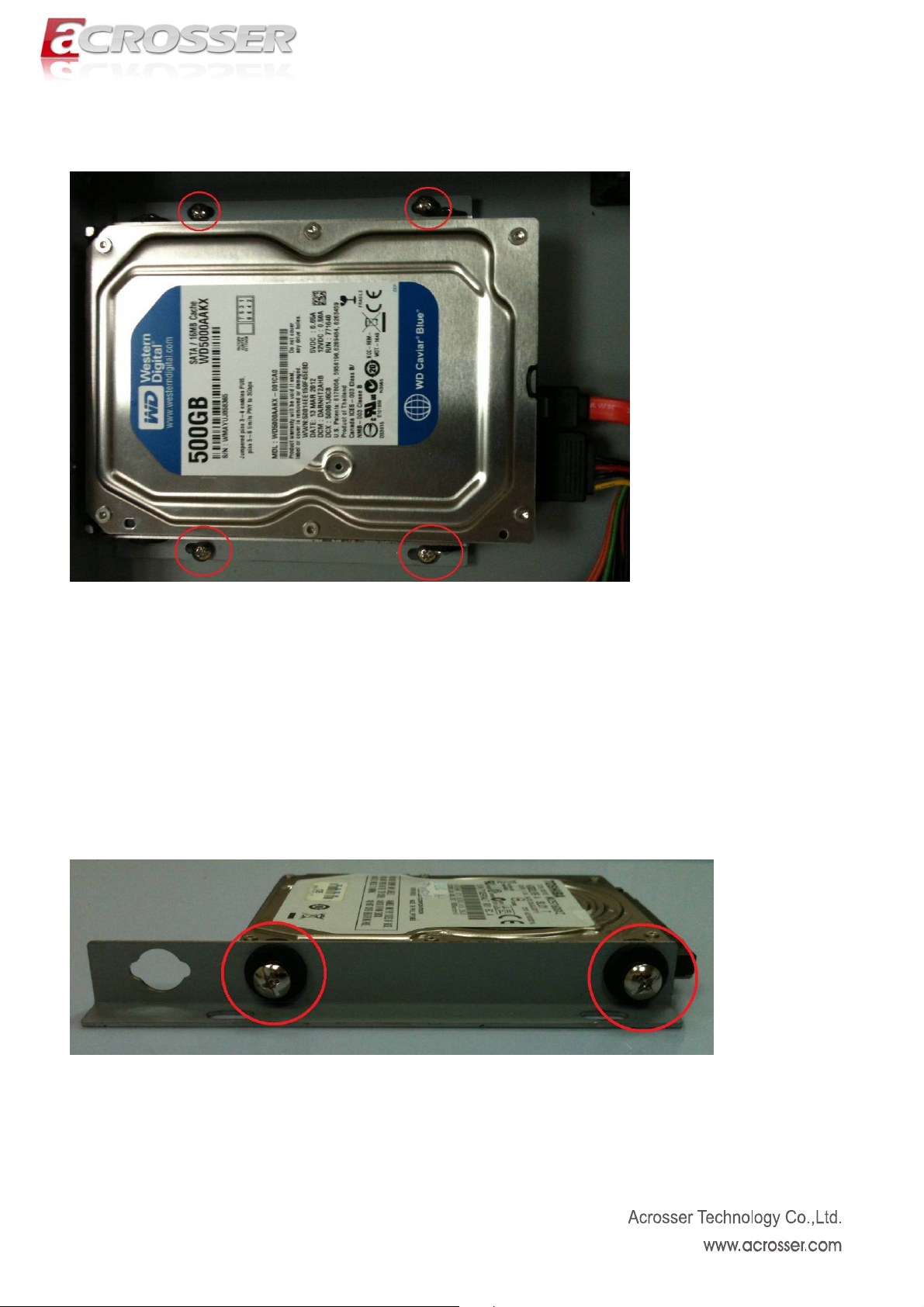
Release 3.5” HDD bracket by unfastening 4 screws.
Fix HDD with HDD bracket by 4 screws.
9
Page 10
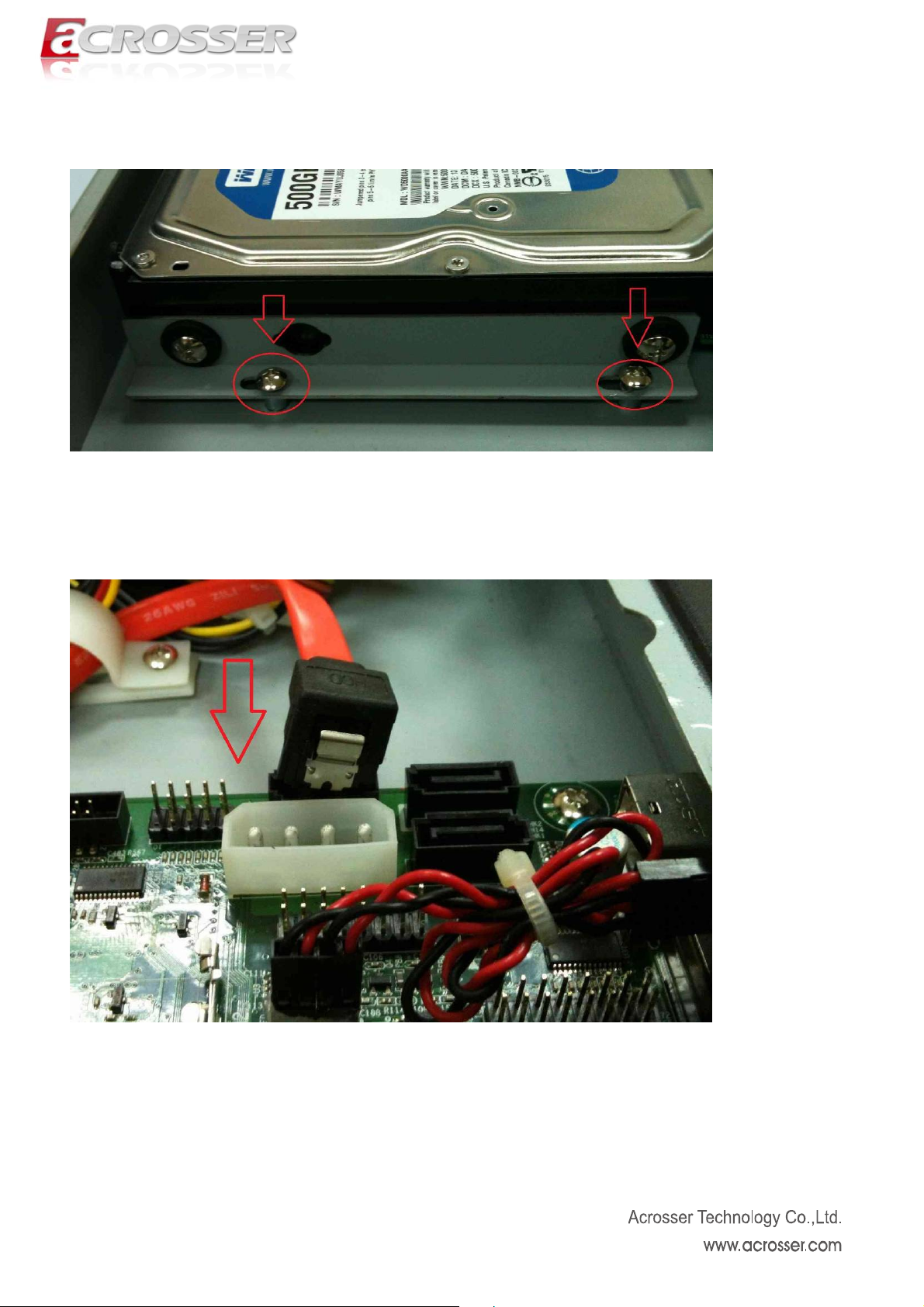
Fix HDD with HDD bracket by 4 screws.
Plug SATA power cable into motherboard.
10
Page 11
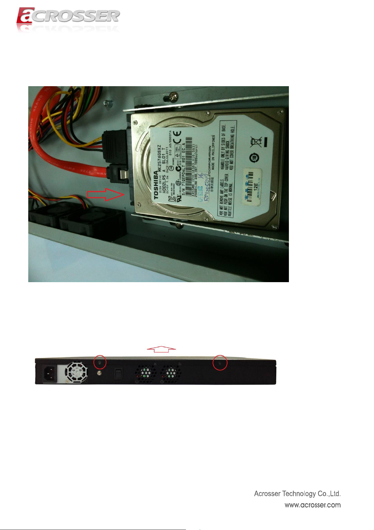
Connect SATA cable and SATA power cable with HDD module.
Assemble top cover back by fastening the 2 screws.
11
Page 12

2.2. CF Card Installation
Open the top cover (the same as above steps).
Release CF Card bracket by unfastening 2 screws
Push CF card into CF socket.
Fix CF card bracket by 2 screws.
12
Page 13

2.3. Installing SO-DIMM DRAM
Open the top cover (the same as above steps).
Install the SO-DIMM in the chassis
2.4. Rack Bracket Installation
Take out the screws and rack bracket from packing bag.
13
Page 14

Fix the Rack bracket to chassis by fastening 6 screws.
14
Page 15

3. AR-B6006 Board Guide
3.1. Introduction
Welcome to the AR-B6006 series Computer. The AR-B6006 series is a Networking board for
Micro-box and Rack-mount with six sets of GbE LAN. Intel Atom (Pineview-D) D525 +ICH8M.
AR-B6006 is a Networking board for micro-box and Rack-mount Platform with Intel Atom D525
+ICH8M, 6 *10/100/1000 LAN with by-pass.
3.1.1. Features
Processor:
AR-B6006D525: Intel® Atom™ Processor D525 (Dual Core, 2X 512K L2 Cache, 1.8
GHz)
Chipset: Intel® ICH8M
Memory: DDR3 800/1333 MHz SO-DIMM, Maximum 4GB
Display: VGA
Storage: 1x CF, 3x SATA II
Communication: 6x Gbps Ethernet, 4x USB 2.0, 2x RS-232
General: Watchdog timer, 4-bit GPIO
15
Page 16

3.1.2. Specification System
Thermal solution FAN connector for CPU FAN
Fan connector for system FAN*2
CPU Intel® Atom™ processor D525 (1M Cache, 1.8
GHz)
System Memory 204-pin DDR3 SO-DIMM socket x2 , DDR3 up
to 4GB, non-ECC and un-buffered
BIOS 1. Support console redirection (default enable)
2. Support bypass setting (default disable)
System Chipset Intel ICH8M
Super I/O Winbond-W8627DHG-P
Network Interface
Ethernet 6 *RJ45
Intel 82574L (10/100/1000Mbps) (L1~L6),
LAN by-Pass LAN1 and LAN2 support by-pass function
LAN3 and LAN4 support by-pass function
Reserve 1*3 pin Jumper for Hardware select
bypass status
I/O
Front panel 1.Power /HDD/Bypass LED:
2.LAN1/ LAN2/ LAN3/ LAN4/LAN5/LAN6 LED:
1000, 10/100, Act.
Rear panel From left to right:
2 * USB (use standby power)
COM port (RJ45)
LAN6/LAN5/LAN4/ LAN3/ LAN2/LAN1
1. 2xUSB 2.0(2.54 mm pitch)
2. Mini-PCI
3. GPIO
4. LPT pin head
Internal I/O
5. Power input
6. KB/MS
7. VGA pin head
8.PWRSW
9. COM-2
Storage
CF 1 x Compact Flash socket
(Master mode) Support UDMA
SATA 3x SATAII interface with power x 1
Others
Watchdog Timer Software programmable 1~255 Seconds,
Battery Lithium Battery, 3V 220mAH (CR2032)
Hardware
monitoring
CPU voltage
CPU and System Temperature
OS support Fedora 14. 64-bit
Ubuntu 10.04 32-bit, Ubuntu 10.04 64-bit
WIN XP 32-bit,
Phoenix
Legacy BIOS
ROM 1MB
Default:
normal
Bypass
16
Page 17
Mechanical
Dimension 210 mm x 140 mm
Operating
0~60oC (32~140oF)
Temperature
Storage
-20~60oC (-4~176oF)
Temperature
Relative
10 to 95% @ 40°C, non-condensing
Humidity
Power Supply N/A
Power
Requirements
24 Pin ATX Power Connector
BIOS Default setting
After power failure [Power On]
3.1.3. Package Contents
Description Q’ty
AR-B6006 Mainboard
1
Driver CD
1
Quick User Manual 1
Console Cable (P/N:190030627-G) 1
VGA Cable 1
17
Page 18
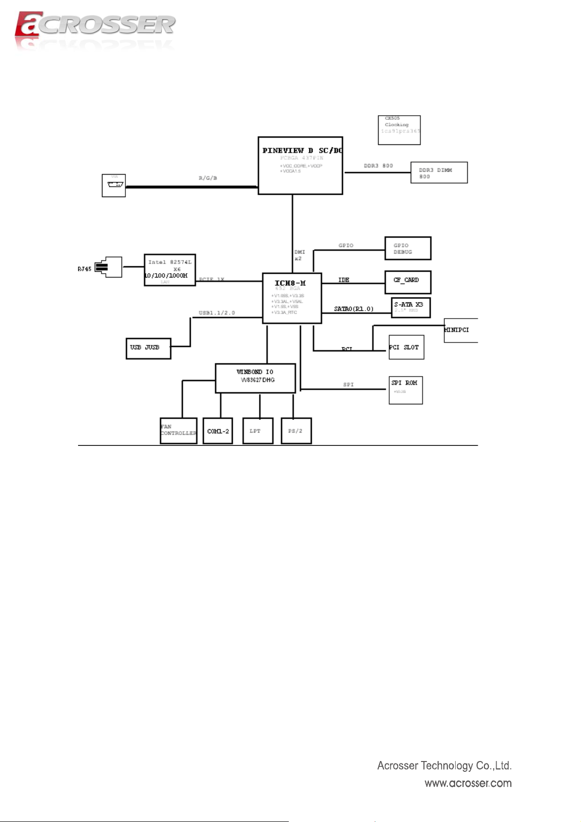
3.1.4. Block Diagram
18
Page 19
3.2. Hardware Information
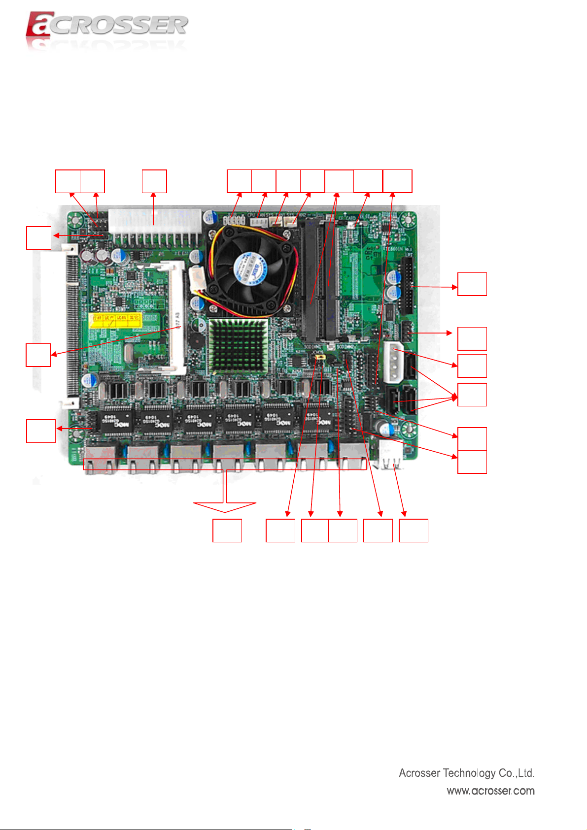
3.2.1. Locations of IO ports & Jumper settings definition
3 4 5
2
6 7 8 9
10
1211
13
1
25
24
2223 2021
14
15
16
17
18
19
19
Page 20
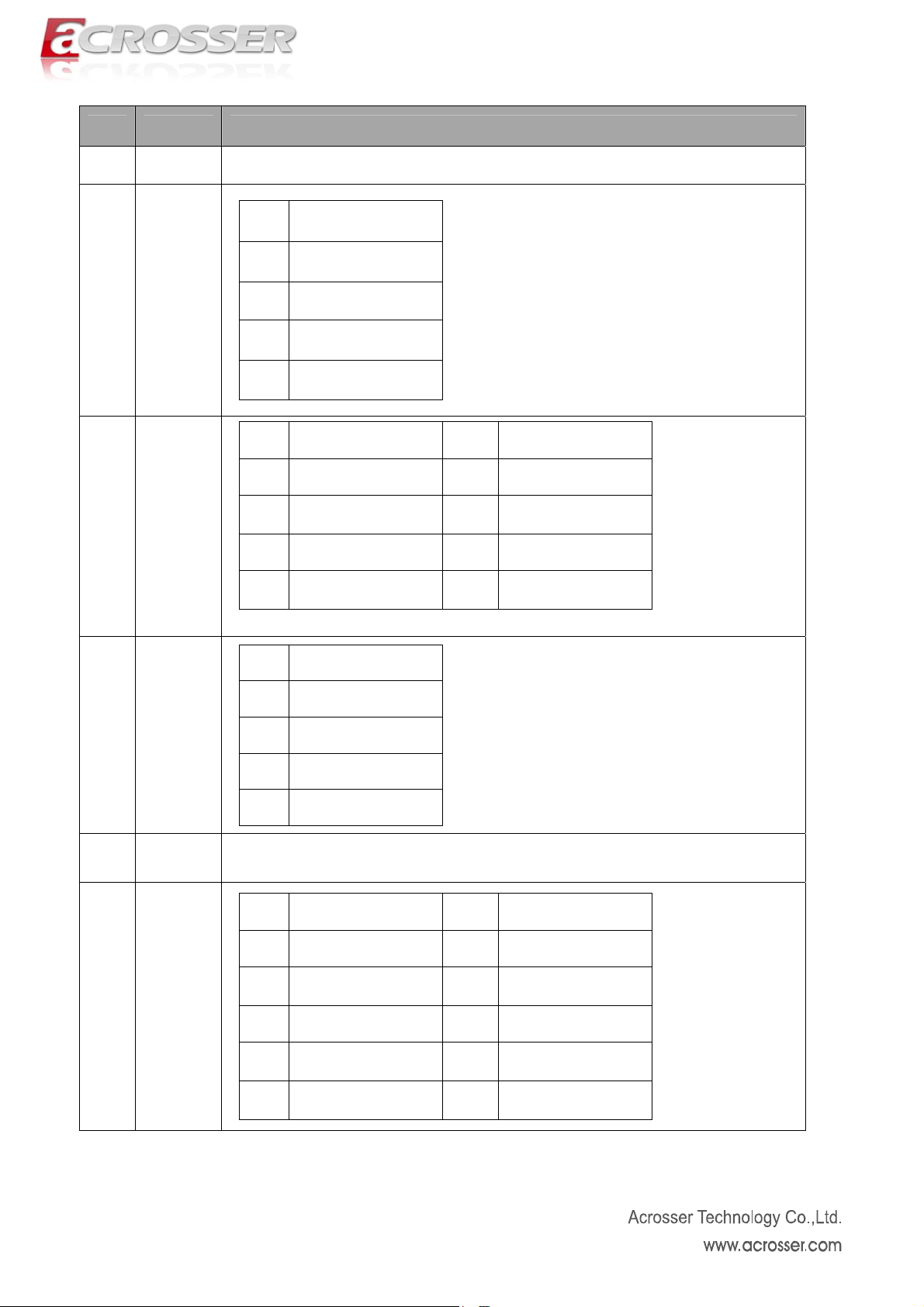
Item Name Description
1 Mini PCI 124 pin mini PCI connector
Pin Description
1 3.3V
J4(LED
2
Board)
J1(GPIO
3
)
4 PWRSW
2 GND
3 3.3V
4 GND
Pin Description Pin Description
1 5v 2 12v
3 GPIO17 4 GPIO20
5 GPIO18 6 GPIO37
7 GND 8 GND
More Detail please see Note.2
Pin Description
1 Power button +
2 Power button 3 Reset +
4 Reset -
5 ATX ATX 20P female connector
Pin Description Pin Description
1 VCC 2 VCC
3 -DATA2 4 -DATA3
6 JUSB
5 +DATA2 6 +DATA3
7 GND 8 GND
9 NULL 10 GND
20
Page 21
7
8
9
10
CPU
FAN
SYS
FAN1
SYS
FAN2
So-DIM
M
11 CF Card
DDR3 SO-DIMM socket
Compact Flash socket
12 VGA
Pin Description Pin Description
1 R 2 GND
3 VCC 4 G
5 GND 6 DDCDA
7 B 8 GND
9 HSYNC 10 VCC
11 VCC 12 VSYNC
13 GND 14 GND
15 DDCCK 16 NC
21
Page 22
Pin Description Pin Description
1 STB 2 AFD
3 D0 4 ERR
5 D1 6 INIT
7 D2 8 SLIN
9 D3 10 GND
11 D4 12 GND
13 LPT
14 COM 2
13 D5 14 GND
15 D6 16 GND
17 D7 18 GND
19 ACK 20 GND
21 BUSY 22 GND
23 PE 24 GND
25 SLCT 26 GND
Pin Description Pin Description
1 DCD 2 RXD
3 TXD 4 DTR
5 GND 6 DSR
7 RTS 8 CTS
9 RI 10 NULL
15
IDE
PWR
4P male power connector
16 SATA Standard SATA connector
Pin rip cripDesc tion Pin Des tion
1 KB_DAT _DAA 2 MS TA
17 J5
3 _CLK S_CLKB 4 M K
5 GND 6 GND
7 VCC 8 VCC
22
Page 23
Pin De Pin De scription scription
1 A
ED
3 A 4 A
L N1_LINK1000#_LED L N1_LINK100_LE
5 A
ED
7 A 8 LA
L N2_LINK1000#_LED N2_LINK100#_L
2 VCC L N1_LINK/ACTIVE#_L
6 VCC L N2_LINK/ACTIVE#_L
18 LAN LED
9 AEDL N3_LINK/ACTIVE#_L 10 VCC
11 A 2 A
L N3_LINK1000#_LED 1 L N3_LINK100#_L
13 A
L N4_LINK/ACTIVE#_L 14 VCC
ED
15 A 6 A
L N4_LINK1000#_LED 1 L N4_LINK100#_L
19 USB USB type A connector
Pin Description
1 HDD ED _L +
D
ED
ED
ED
20
PWR/HD
LED
2 HDD ED _L 3 PWR ED+ _L
4 PWR ED _L -
21 J6
1- 2PIN,Auto Power ON;2-3PIN,Manual Power On
Default setting : 1-2 Auto Power on
Pin 1-2 2-3
22 JCMOS
Define Normal Clear cmos
Default 1-2 Normal
1- 2PIN,Watchdog Control System Reset;
2- 2-3PIN,Watchdog Control BYPASS
23
J3(WDT
Select)
Default :2-3 Watchdog Control Bypass
24 LAN RJ45 connector
23
Page 24

Pin rip cripDesc tion Pin Des tion
1 VCC 2 BYPASS1-N
3 VCC 4 PASSBY 1
25
Bypass
LED
5 VCC 6 BYPASS2-N
7 VCC 8 PASSBY 2
9 ULL 0 NC N 1
Note 1. It can not use USB Hub with power adaptor that connects to USB port.
Note 2. When the screen of VGA output disappears, please use HotKey (Ctrl +
Alt + F1) to call the screen back.
Note 3. Appendix A GPIO Mapping table
GPIO17 ------ Output Default Low
GPIO18 ------ Output Default Low
GPIO20 ------ Output Default Low
GPIO37 ------ Output Default Low
GPIO Base Address: 0x1180
GPIO17 Enable GPIO17: 0x1182 bit1 1: Enable
GPIO17 Input/output Select: 0x1186 bit1 0: Output 1: Input
GPIO17 Level: 0x118E bit1
GPIO18 Enable GPIO18: 0x1182 bit2 1: Enable
GPIO18 Input/output Select: 0x1186 bit2 0: Output 1: Input
GPIO18 Level: 0x118E bit2
GPIO20 Enable GPIO20: 0x1182 bit4 1: Enable
GPIO20 Input/output Select: 0x1186 bit4 0: Output 1: Input
GPIO20 Level: 0x118E bit4
GPIO37 Enable GPIO37: 0x11B0 bit5 1: Enable
GPIO37 Input/output Select: 0x11B4 bit5 0: Output 1: Input
GPIO37 Level: 0x11B8 bit5
24
Page 25
3.3. BIOS Setting
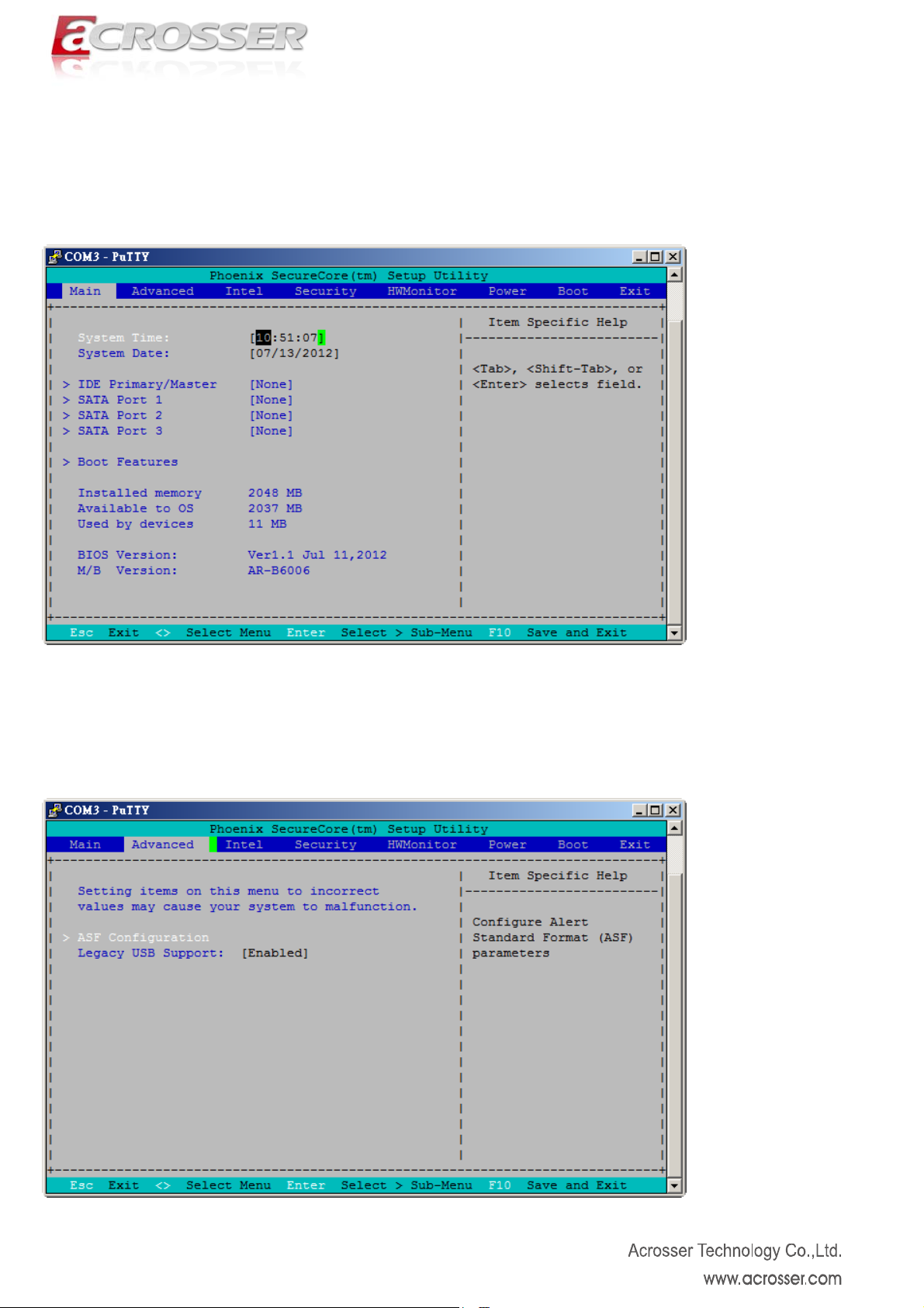
3.3.1. Main (System Overview)
The BIOS setup main menu includes some options. Use the [Up/Down] arrow key to highlight the
option that you wish to modify, and then press the [Enter] key to select the item and configure the
functions.
3.3.2. Advanced (Advanced Settings)
The <Advanced > menu consists of configuration entries that allow you to improve your system
performance, or let you modify some system features according to your preference. Some entries
are required and reserved by the board’s design.
25
Page 26

3.3.3. Intel
Use the Intel BIOS menu to access the CPU and ICH(southbridge) configuration menus.
3.3.4. Security
The BIOS provides a Supervisor and a User password. If you use both passwords, the Supervisor
password must be set first.
26
Page 27

3.3.5. HWMonitor
This section shows the parameters in determining the Hardware Monitor Status. These parameters
include temperatures, fan speeds, and voltages.
3.3.6. Power
This option determines the configuration of power management.
27
Page 28

3.3.7. Boot(Boot Setting)
This option allows user to select sequence/priority of boot device(s).
3.3.8. Exit
This option is use to exit the BIOS main menu and change password.
28
Page 29

Appendix
Appendix A - Driver Installation and Programming Guide (Windows)
A-1 GPIO and Watchdog
Overview
AR-B6006 provides both a GPIO interface and a Watchdog timer. Users can use the GPIO and
Watchdog APIs to configure and to access the GPIO interface and the Watchdog timer. The GPIO
has four input pins and four output pins. The Watchdog timer can be set to 1~255 seconds. Setting
the timer to zero disables the timer. The remaining seconds of the timer to reboot can be read from
the timer.
In this GPIO and Watchdog package, we provides:
1. API Library.
2. GPIO and Watchdog test tool and the tool source code.
Driver Installation
Super I/O Driver Folder
Click the file SetupDriver.exe to install Super I/O driver.
29
Page 30

(Driver installation completely)
Files Description
SuperIoAPI.h: This file contains all define values and structures, it should be included in your
application program source code.
SuperIoAPI.lib: This file contains all API func tions library, it’s for static linking with your application
program source code.
SuperIoAPI.dll: This file contains all API functions library, it’s for dynamic linking with your application
program source code.
A-2 API List and Descriptions
GPIO and Watchdog
GPIO
Notice: Before using GPIO
GPIO pins defines below:
#define GPO_BIT_17 17
#define GPO_BIT_18 18
#define GPO_BIT_20 20
#define GPO_BIT_37 37
#define LED1 GPO_BIT_17
#define LED2 GPO_BIT_20
#define LED3 GPO_BIT_18
#define LED4 GPO_BIT_37
BOOL WINAPI SuperIo_Open();
Remarks:
You must call this function at start-up of application to open Super I/O device.
APIs, be sure Super I/O driver has installed successfully.
30
Page 31

Parameters:
( None )
Return Value:
Returns TRUE on success.
If the Super I/O driver has not installed, return FALSE.
void WINAPI SuperIo_Close();
Remarks:
You must call this function at end of application to close Super I/O device.
Parameters:
( None )
Return Value:
( None )
BOOL WINAPI Gpio_GetBitValue( int nBit, BYTE* pValue );
Remarks:
Call this function to get GPIO pins value.
Parameters:
nBit
Stand for GPIO pins, you can assign value LED1 ~ LED4, or value GPO_BIT_17,
GPO_BIT_18, GPO_BIT_20, GPO_BIT_37.
pValue
Pointer of variable to retrieve GPIO pins state.
Return Value:
Returns TRUE on success, FALSE on failure.
BOOL WINAPI Gpio_SetBitValue( int nBit, BYTE bValue );
Remarks:
Call this function to Set GPIO pins value.
Parameters:
nBit
Stand for GPIO pins, you can assign value LED1 ~ LED4, or value GPO_BIT_17,
GPO_BIT_18, GPO_BIT_20, GPO_BIT_37.
bValue
Output value of GPIO pins, value 1 or 0.
Return Value:
Returns TRUE on success, FALSE on failure.
Watchdog
Notice: Before using GPIO
APIs, be sure Super I/O driver was installed successfully.
31
Page 32

typedef enum _E_TIME_UNIT {
TIME_UNIT_SECOND,
TIME_UNIT_MINUTE,
} E_TIMER_UNIT;
BOOL WINAPI SuperIo_Open();
Remarks:
You must call this function at start-up of application to open Super I/O device.
Parameters:
( None )
Return Value:
Returns TRUE on success.
If the Super I/O driver has not installed, return FALSE.
void WINAPI SuperIo_Close();
Remarks:
You must call this function at end of application to close Super I/O device.
Parameters:
( None )
Return Value:
( None )
BOOL WINAPI WatchDog_GetTimerCount( int* pCount );
Remarks:
Call this function to get value of current WatchDog Timer.
Parameters:
pCount
Pointer of variable to retrieve WatchDog Timer value.
Return Value:
Returns TRUE on success, FALSE on failure.
BOOL WINAPI WatchDog_GetTimerUnit( int* pTimerUnit );
Remarks:
Call this function to get unit of current WatchDog Timer, minute or second.
Parameters:
pTimerUnit
Pointer of variable to retrieve WatchDog Timer unit.
Return Value:
Returns TRUE on success, FALSE on failure.
BOOL WINAPI WatchDog_StartTimer ( int nTimerCount, int nTimerUnit );
32
Page 33

Remarks:
Call this function to start WatchDog Timer.
Parameters:
nCount
Timer value of WatchDog.
Value 2 ~ 255 if timer unit is second.
Value 1 ~ 255 if timer unit is minute.
nTimerUnit
TIME_UNIT_SECOND and TIME_UNIT_MINUTE stand for second and minute.
Return Value:
Returns TRUE on success, FALSE on failure.
BOOL WINAPI WatchDog_StopTimer();
Remarks:
Call this function to stop WatchDog Timer.
Parameters:
(None)
Return Value:
Returns TRUE on success, FALSE on failure.
33
Page 34

Appendix B - Programming Guide (Linux)
B-1 GPIO and Watchdog
Overview
AR-B6006 provides both a GPIO interface and a Watchdog timer. Users can use the GPIO and
Watchdog APIs to configure and to access the GPIO interface and the Watchdog timer. The GPIO
has four output pins. The Watchdog timer can be set to 1~255 seconds. Setting the timer to zero
disables the timer. The remaining seconds of the timer to reboot can be read from the timer.
In this GPIO and Watchdog package, on Linux and Windows platform, we provides:
GPIO and Watchdog test utility.
File Descriptions
GPIO and Watchdog
On Linux plat
1. Libw83627.h
This file includes the declarations of the APIs and macro definitions.
2. maintest.c
The source code of the utility.
3. Libw83627.a
The file is static link file.
B-2 API List and Descriptions
GPIO and Watchdog
GPIO
1. Syntax:
Get_gpo_status(int pin)
Description: Get the value of GPIO Output and put the value at *val.
Parameters:
I. The parameter ‘channel’ indicates the GPIO Output pins to show. Users can use the
Return Value: If the function gets the values successfully, it returns status.
2. Syntax:
form:
GPO0, GPO1, GPO2, GPO3 to indicate the GPIO Outpurt channel.
Set_gpio(int pin, int value)
Description: Set the status of GPIO Output value.
Parameters:
Set value 0 is Low, 1 is High
34
Page 35

Watchdog
1. Synt
ax:
Wdt_start(Void)
Description: This function read the value of the watchdog time counter and returns it to the
caller.
Parameters: None.
Return Value: This function returns the value of the time counter and returns it to the caller as
an unsigned character.
2. Syntax:
Wdt_stop(Void)
Description: Any time call this function will stop Watchdog Timer.
Parameters: The parameter ‘val’ is the value to set to watchdog timer register. The range is 1~
255.
Return Value: None.
3. Syntax:
Get_wdt_count()
Description: This function read the value of the watchdog time counter.
Parameters: None.
Return Value: This function returns the value of the time counter.
35
 Loading...