

Page 1

AR-R5700 Serial
Installation Guide
1
Page 2

Contents
Introduction of AR-R5700serial…………
1
1-1 Discrimination………………………………
1-2 Packing List
Procedure of Assembly/Disassembly………………………………
2
2-1 Installing the 2.5”or3.5”Disk Drive(HDD)………………...
2-2 Installing the Memory card……………………………………
2-3 Installing Extension PCI card ………………………
03
03
03
04
04
07
08
2-4 Installing CPU and HeatsinkModule ………………………
10
2
Page 3
1. Introduction of AR-R5700 Series
AR-R5700 series is a 1U height, rack-mounted system product. It is designed mainly for
networking applications. With powerful Intel CPU core & an expansion module in option for
optical/copper-wire LAN interface, AR-R5700 can satisfy the user requirements in performance
and complex networking configurations. Besides, excellent operating temperature at least 45℃
reliability, it can be installed in more severe environment than a generally commercial network
device.
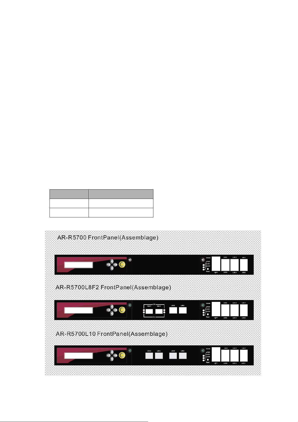
AR-R5700 has diverse physical interface in the front panel (fiber interface in option), such as up to
10 Giga LAN ports, two fiber LAN ports in option, build-in LEDs, 2 USB Ports, one Console port,
Power Button, Reset Button, and Keyboard/Mouse interface. In addition, the system can be
extended SSD/memory capacity via adding-in DRAM module and CF card according to the users
needs.
1.1 Discrimination (included Rubber Foot)
Description AR-R5500
CPU Board AR-B5700series
Dimensions
440×44×448 (mm)
3
Page 4
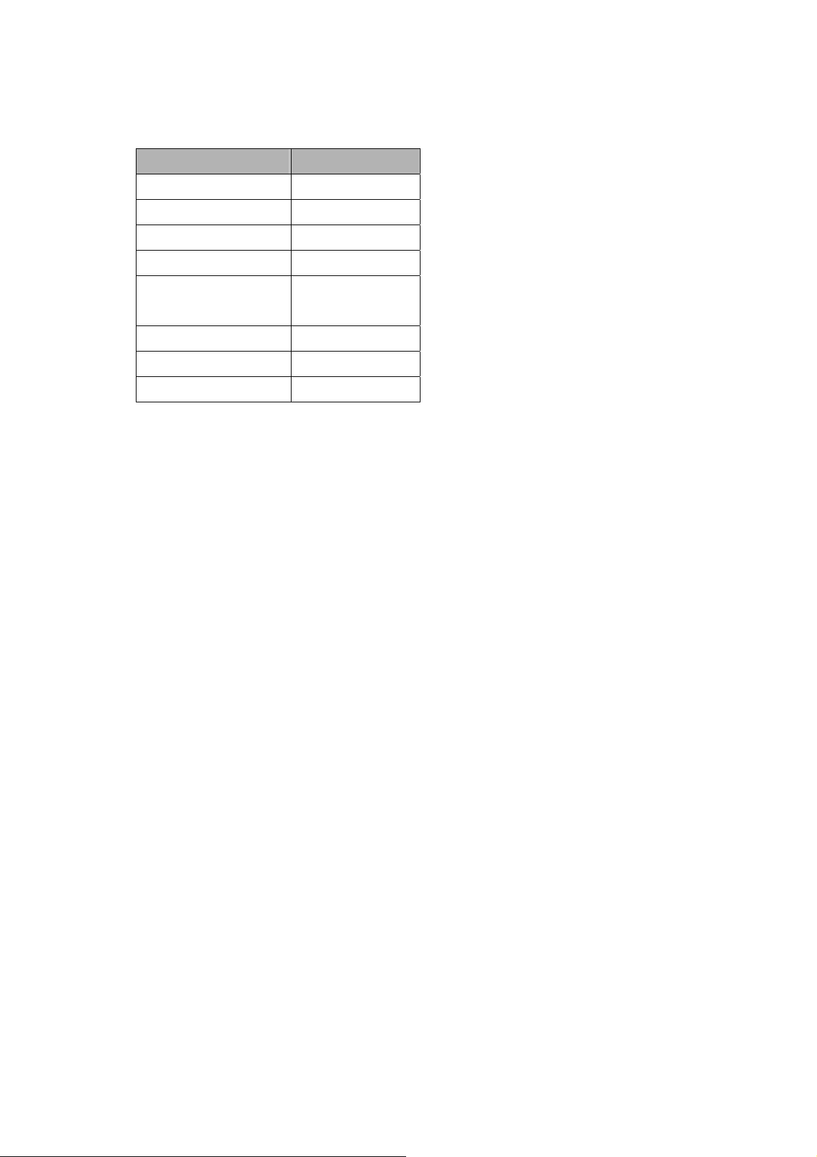
1.2 Packing List
Description Q’ty
AR-R5700serial
Power Core 1
CD 1
KB/MS Cable 1
Mounting Bracket
(+screw)
Console cable 1
SATA Cable (HDD) 1
Quick user manual 1
1
2
4
Page 5

2. Procedure of Assembly/Disassembly
2-1 Installing the 2.5”/3.5”Hard Disk Drive (HDD)
The following are step-by-step installation.
1. Remove the AC-power via un-plug the power cord of AR-R5700.
2. Unlock the two screw-nuts on top-edge to remove the top-cover out from
AR-R5700, as Fig-01.
Fig. 01 Remove the top cover
3. Insert the rubbers into the HDD bracket in four edges.
4. Place HDD body into the HDD bracket and lock HDD and Bracket
together by screws (4pcs), as Fig-02.
Fig-02 HDD bracket with HDD body
5
Page 6

5. Connect the SATA cable to the SATA connector of HDD,
6. Place the HDD module (HDD+HDD bracket) back to the case
7. Fix the HDD bracket to the chassis by four screws, as Fig-03.
Installing screws
Fig-03. Lock HDD bracket with SATA cable
6
Page 7

8. Tighten the two screw-nuts on the top edge of AR-R5700, as Fig-04.
Fig-04 Lock the top cover
7
Page 8

2-2 Installing CF card
The following are step-by-step installation.
1. Unlock the two screw-nuts on top-edge to remove the top-cover out from
AR-R5700, as Fig-05.
Fig-05 Lock the top cover
2. Install the CF card & Min-PCI device
Insert the mini-PCI
module into the
mini-PCI socket
Insert the CF card
into the CF card
socket
Fig-06 Install the card
8
Page 9

2-3 Installing Extension Module Options (PCI-E)
The following are step-by-step installation for PCI-E Module (LAN expansion
module).
1. Unlock the two screw-nuts on top-edge to remove the top-cover out from
AR-R5700, as Fig-05 & Fig-07.
Extension LAN Module
Fig-07 AR-R5700series Extension Module Options View
9
Page 10

2. Remove the dummy bracket (default for AR-R5700) out from the PCI-E
slot via unlock the screws on the front-side of chassis, as shown in Fig-08.
Unscrew
PCI-E slot
Take out
PCI-E slot
Unscrew
Fig-08. Unlock the screws for PCI-E (Modules) card
3. Tighten the PCI-E cards (modules) via locking the screw-nuts as shown in
Fig-09
Screw driver on lock
Fig-09 Lock PCI card
10
Page 11

2-4 Installing CPU and Heatsink Module
The following are step-by-step instructions for CPU and Heatsink Module.
1. Take out the air-flow tunnel of AR-R5700, as Fig-11
Fig-11 Take out the air-flow tunnel
11
Page 12

2. Take out the Heatsink Module via loosing the screws of the Heatsink
Module, as Fig-12
Please put here
thermal glue!
Step-4
Step-2
Step-1
Step-3
Fig-12 Take out the Heatsink Module
12
Page 13

Appendix
CPU in support
Intel Proc No Clock Speed Cache FSB Note
Core 2 Duo
processor
Core 2 Duo
processor
Core 2 Duo
processor
Core 2 Duo
processor
Core 2 Duo
processor
Core 2 Duo
processor
Core 2 Duo
processor
Celeron D processor 440 2.0GHz 512K 800
Celeron D processor 420 1.6GHz 512K 800
E8400
E8300
E6700
E6600
E6400 2.133 2M 1066
E4300 1.8 2M 800
E2160 1.8 1M 800
3G
6M 1333
2.83G
6M 1333
2.66G
4M 1066
2.4G
4M 1066
Note:
Standard product support CE, FCC Class A only. For extra certification, it is belonged to
customer’s demands.
13
 Loading...