

Page 1

AR-R5205FL Installation Guide
®
ACROSSER
AR-R5205FL
Fanless Rack 1U Celeron/Pentium M CPU,
910GMLE+ICH6M, FSB 400 MHz Processors
with 6 LANs
Installation Guide
Edition: 1.0
1
Page 2

AR-R5205FL Installation Guide
Contents
Introduction of AR-R5205FL………………………………
1
1-1 Product description………………………………………….
1-2 Packing List……………………………………………
Procedure of Assembly/Disassembly…………………………….
2
2-1 Installing the 2.5”Hard Disk Drive(HDD)…………………….
2-2 Installing the Memory or mini PCI card……………………………………
2-3 Installing the PCI card……………………………………
Appendix……………………………………
03
03
05
06
06
09
10
12
2
Page 3
AR-R5205FL Installation Guide
1. Introduction of AR-R5205FL
AR-R5205FL is a Fan-less system prod uct mainly for industry PC applications. With powerful Intel
CPU core & diverse memory cards extension (mini-PCI, CF, SO-DIM), AR-R5205FL can satisfy
the users requirements in any industry application environment, especially in n etworking fields.
AR-R5205FL has diverse physical interface in the rear and front panel, such as 6*10/100/1000
LANs connectors, build-in LEDs, 2 USB Ports, one COM port, AT Power Button & Reset Button,
AC inlet. In addition, the system provides the capacity for extending I/O device by adding DRAM or
PCI card & CF card depends on users needs.
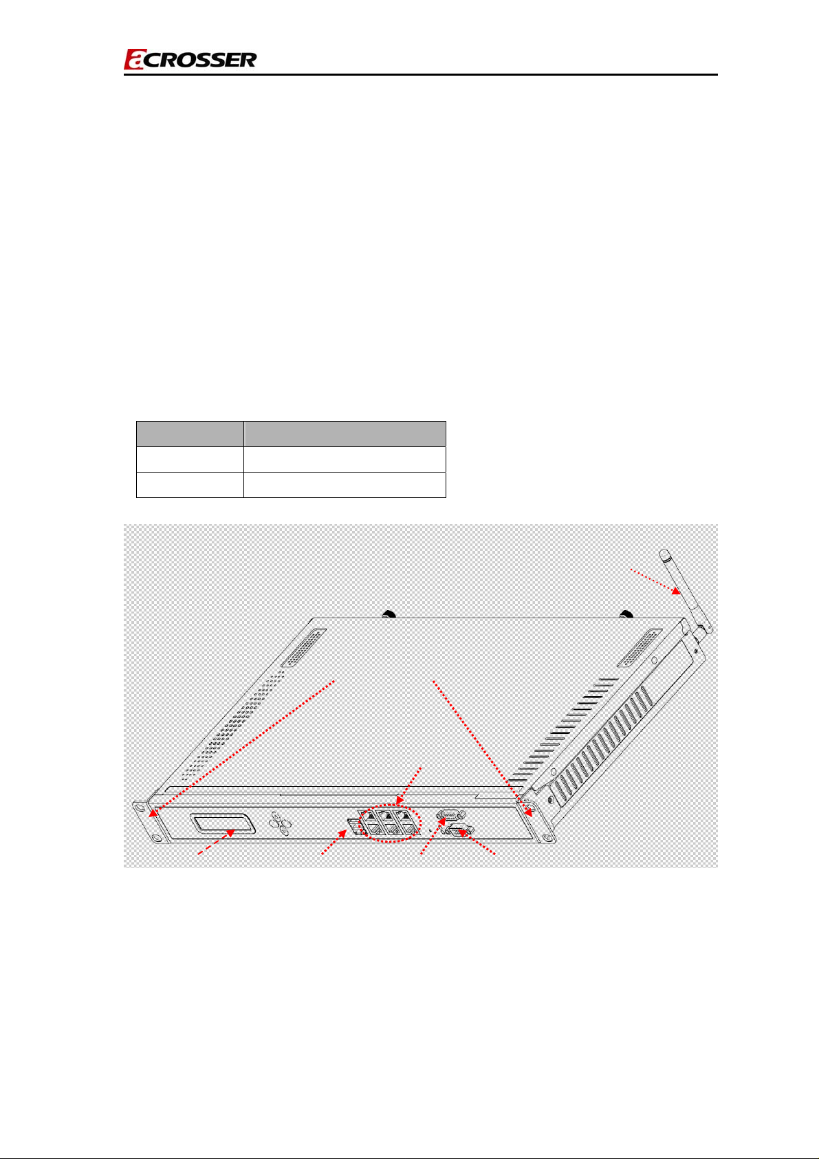
1.1 Product description.
Description AR-R5205FL Serial
CPU Board AR-B5205 series
Dimensions (X)442(Y)44(Z)249(Unit:mm)
mount bracket(Rack)
LCM
USB
LANs Port
Antenna
COM Port VGA Port
AR-R5205FL product 3D outlines(Front)
3
Page 4
AR-R5205FL Installation Guide
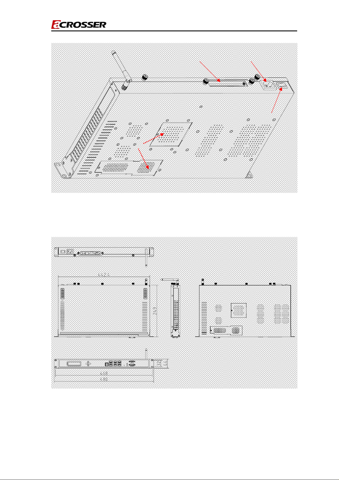
PCI_Inlet
Extend doors
AR-R5205FL product 3D outlines(Rear)
AC_Inlet
PowerSwitch
AR-R5205FL product 2D outlines
4
Page 5

AR-R5205FL Installation Guide
AR-R5205FL Menbrane
1.2 Packing List
Description Q’ty
AR-R5205FL 1
Power Core 1
Mount Bracket(Rack ;screws-4PCS) 2
CD 1
SATA Power Cable 1
SATA Cable 1
KB/MS Cable 1
QuIck user manual 1
2.5”HDD Bracket (screws-8PCS) 1
5
Page 6

AR-R5205FL Installation Guide
2. Procedure of Assembly/Disassembly
2-1 Installing the 2.5”Hard Disk Drive (HDD)
The following are step-by-step installation
1. Remove the power cord out from the AR-R5205FL
2. Unscrew the two screws in top cover of AR-R5205FL, as shown in Fig-01.
Push(Open)
Push(Open)
Unscrew Unscrew
Fig- 01 Remove the top cover
3.Insert the rubbers into the HDD bracket, as shown in Fig-02-1.
4.Place HDD body into HDD bracket and lock HDD body and bracket by screws
(4pcs), as shown in Fig-02-2.
Install the rubbers on the HDD bracket.
Fig-02-1 Install the rubbers with HDD body
6
Page 7

AR-R5205FL Installation Guide
Screws up
Fig-02-2 HDD bracket with HDD body
5. Connect SATA cable to HDD module (HDD+HDD bracket)
6. Place HDD module back to the case
7. Lock HDD module to the chassis by four screws and put HDD with SATA
cable, as Fig-03.
SATA Power connect
SATA Connect
Lock up the screws
Fig-03 Lock HDD bracket / Lock SATA power connect with SATA connect
7
Page 8

AR-R5205FL Installation Guide
8. Lock the two screws in top cover of AR-R5205FL, as shown in Fig-04.
Pay attention to making a reservation to click!
Push(Close)
Fig-04-1 Locked the top cover
Push (Close)
Locked up Locked up
Fig-04-2 Locked the top cover
8
Page 9

AR-R5205FL Installation Guide
2-2 Installing CF and mini PCI Cards or OS-DIM
The following are step-by-step installation
1. Remove the extending doors by removing the screws, as shown in Fig-05
Unscrew when installing the mini-PCI Card .
Warning Label
Unscrew when installing the SO-DIM or CF card.
Fig-05-1 Remove the extending doors by removing the screws.
The direction for installing the Mini-PCI/Wifi card
The direction for installing the SO-DIM
Fig-05-2 Install the cards in the chassis
The direction for installing the CF cards
9
Page 10

AR-R5205FL Installation Guide
2-3 Installing Extension PCI Card
The following are instructions for PCI card installation.
1. AR-R5205FL can be extended with a PCI card.
2. Unscrew the two screws in top cover of AR-R5205FL, as Fig-01.
3. Remove the dummy bracket in PCI slot via unlock the screws as shown in
Fig-06.
Unlocked the screws
Fig-06. unlock the screws for PCI card
4. Lock the holder and riser card via locking the screw as shown in Fig-07.
Locked up
Fig-07 Locked the PCI card
10
Page 11

AR-R5205FL Installation Guide
5. Plug in the extension PCI card into Riser card and adjust the card into the
holder as shown in Fig-08.
1.)Plug in the PCI card
2.)Locked the screws
Fig-08 Install the PCI card
11
Page 12

AR-R5205FL Installation Guide
Appendix
NOTICE:
Please don't change CPU by yourself. Any disassembly and assembly for
the CPU thermal module will cause unexpected damage,as Fig-09.
Please do contact Acrosser customer survice center/FAE in case changing
CPU .
Please don't dissemble and install
the thermal module by yourself
Fig-09 Caution: Please don't dissemble and install the thermal module by yourself.
12
 Loading...