

Page 1

Revision: 1.0
AR-N8601FL
System Guide
Revision Description Date
1.0 Release 2010/01/11
1
Page 2

Revision: 1.0
Contents
AR-N8601FL System Guide
1 Introduction......................................................................................... 4
1.1 Specifications.................................................................................................4
1.2 Packing List....................................................................................................5
1.3 System Dissection.........................................................................................5
2 Procedures of Assembly/Disassembly............................................. 8
2.1 Installing the CF card........................................................................ 8
AR-B8601 Board Guide
1 Introduction........................................................................................11
1.1 Package Contents........................................................................................11
1.2 Block Diagram..............................................................................................12
2 H/W Information................................................................................ 13
2.1 Locations (Top side)....................................................................................13
2.2 Connectors and Jumpers Location............................................................14
2.3 Jumpers and Connectors Pin define..........................................................15
3 WATCHDOG, GPIO PROGRAMMING............................................... 17
4 BIOS Setting...................................................................................... 24
4.1 Main Setup....................................................................................................25
4.2 Advanced Chipset Setup.............................................................................27
4.3 Power Setup .................................................................................................29
4.4 PnP/PCI Setup..............................................................................................30
4.5 Peripherals Setup.........................................................................................32
4.6 PC Health Setup...........................................................................................34
2
Page 3

Revision: 1.0
4.7 Boot Setup....................................................................................................35
4.8 Exit Setup .....................................................................................................36
3
Page 4

Revision: 1.0
AR-N8601FL System Guide
1 Introduction
Acrosser Microbox Networking device AR-N8601FL, It is a small, cost-effective,
Fanless and entry-level UTM (Unified Threat Management) hardware, which is
suitable for small office. Base on VIA CN700 with ULV Eden 500MHz CPU, the
AR-N8601FL general very low heat to follow the low power consumption trend.
With Fanless design, the AR-N8601FL can keep longer lifetime. This is an important
feature for 24 hours networking device.
By three 10/100 RJ-45 LAN’s, the AR-N8601FL is sufficient for the small
business security hardware solution.
Key features:
VIA EDEN ULV 500 CPU.
VIA CN700+8237R plus Chipsets.
DDRII memory support (533MHz).
3 x 10/100LAN RTL8100C.
CF socket, 1x SATA, SATA power, and 2 x USB.
Console, VGA (pinhead), KB/MS (Pinhead).
Support PXE boot from LAN.
Compact size.
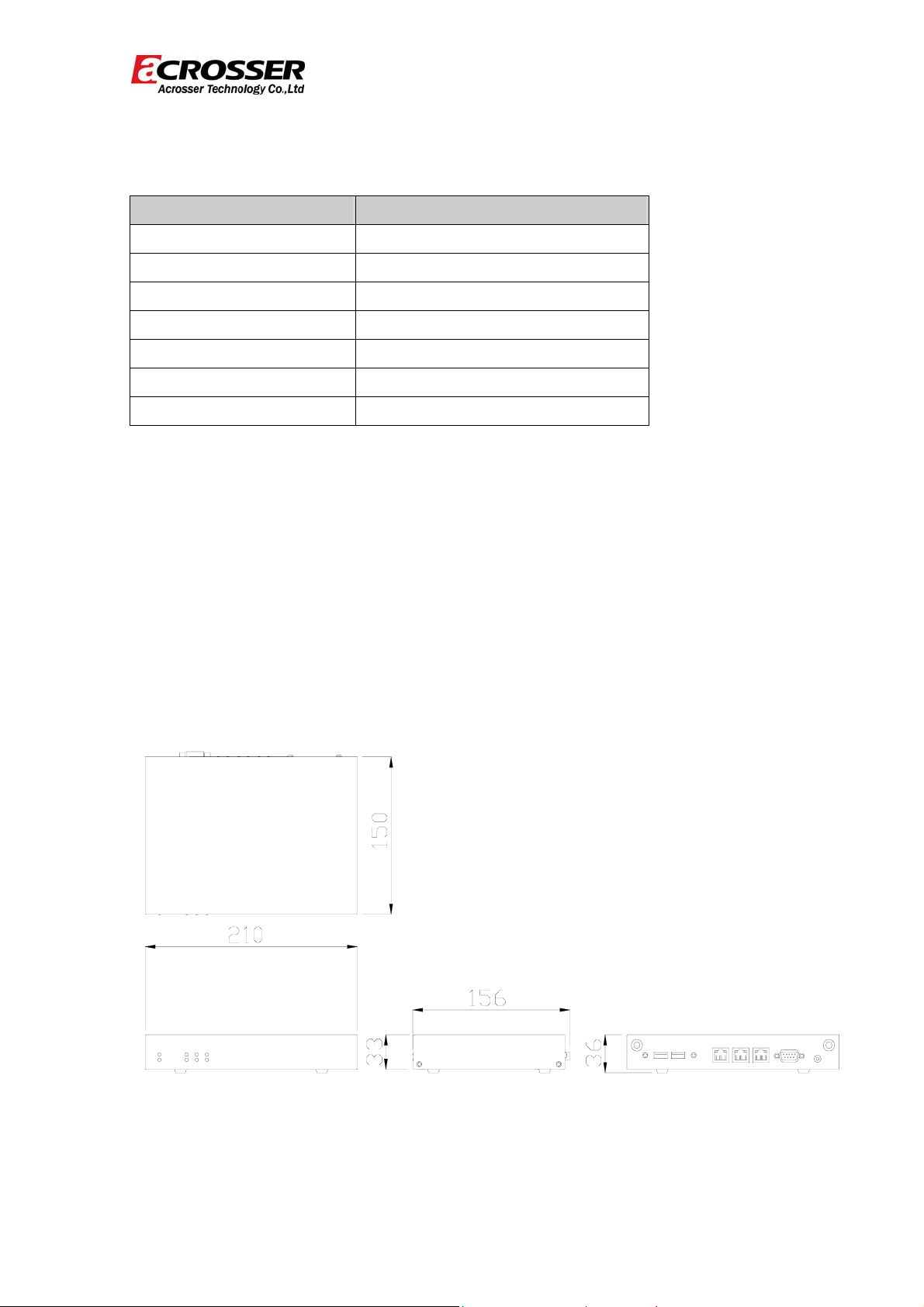
1.1 Specifications
System : AR-N8601FL
CPU Board : AR-B8601
Dimensions : 210*150*33(mm)
4
Page 5
1.2 Packing List
Description Quantity
AR-N8601FL 1
Console cable 1
VGA cable 1
Software driver CD 1
Quick user’s manual 1
Power adaptor 1
Power cord 1
Revision: 1.0
1.3 System Dissection
(1) Dimensions
5
Page 6
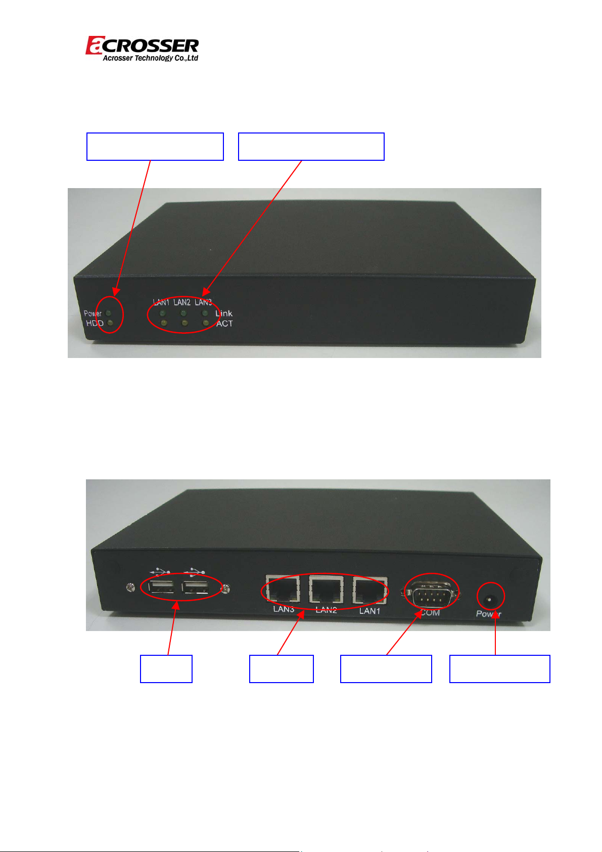
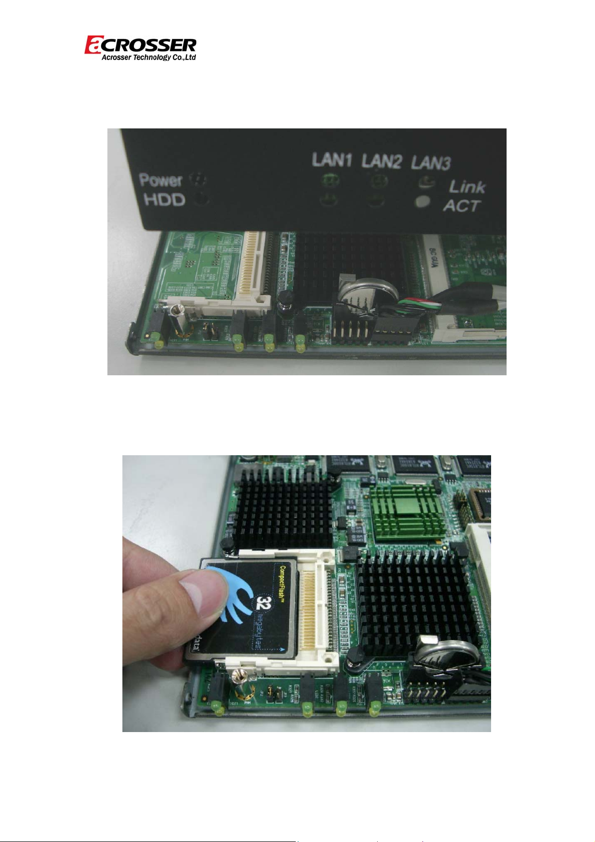
(2) Front Panel
Led (Power & HDD)
Revision: 1.0
LAN led (Link & ACT)
Back Panel
USB*2
LAN1~3 COM PORT POWER JACK
6
Page 7
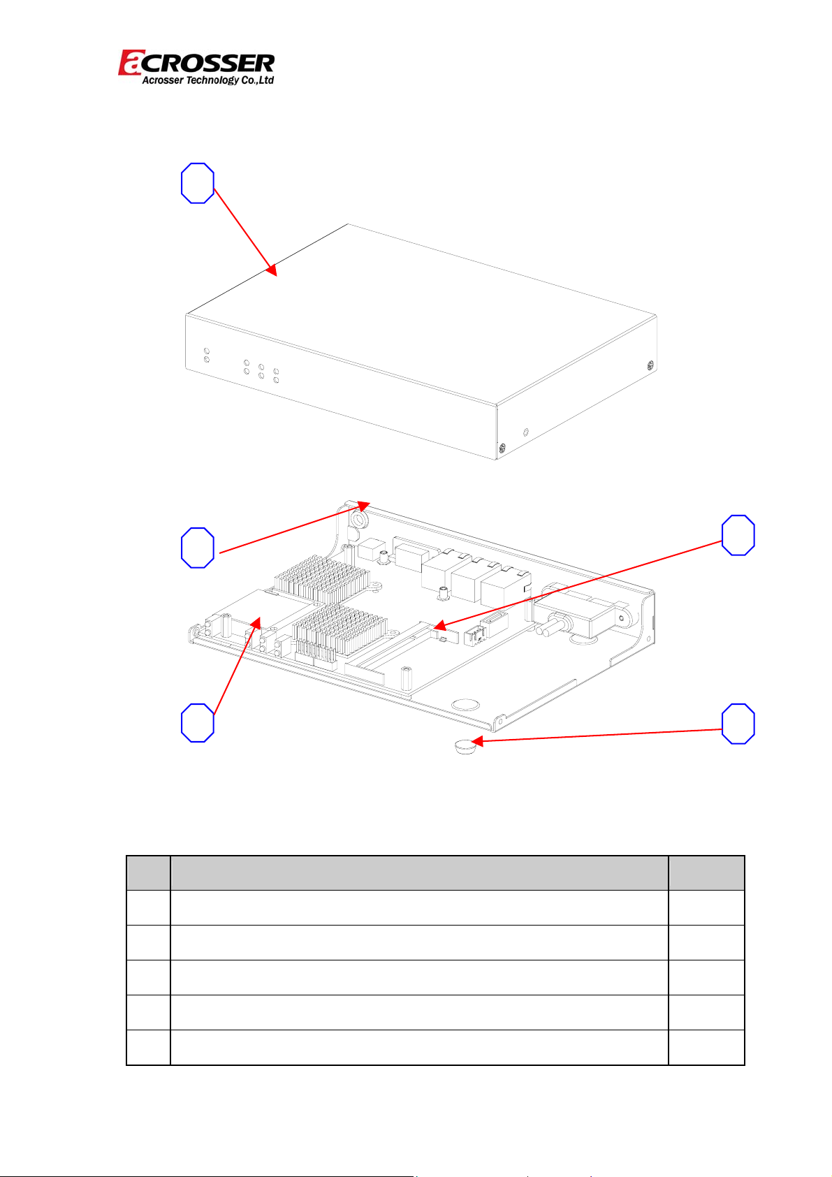
(3) System Configuration
1
Revision: 1.0
2
3 5
Item Description Quantity
1 TOP COVER 1
4
2 BOTTOM BASE 1
3 CF SOCKET 1
4 RAM SOCKET 1
5 FOOT PAD 4
7
Page 8
Revision: 1.0
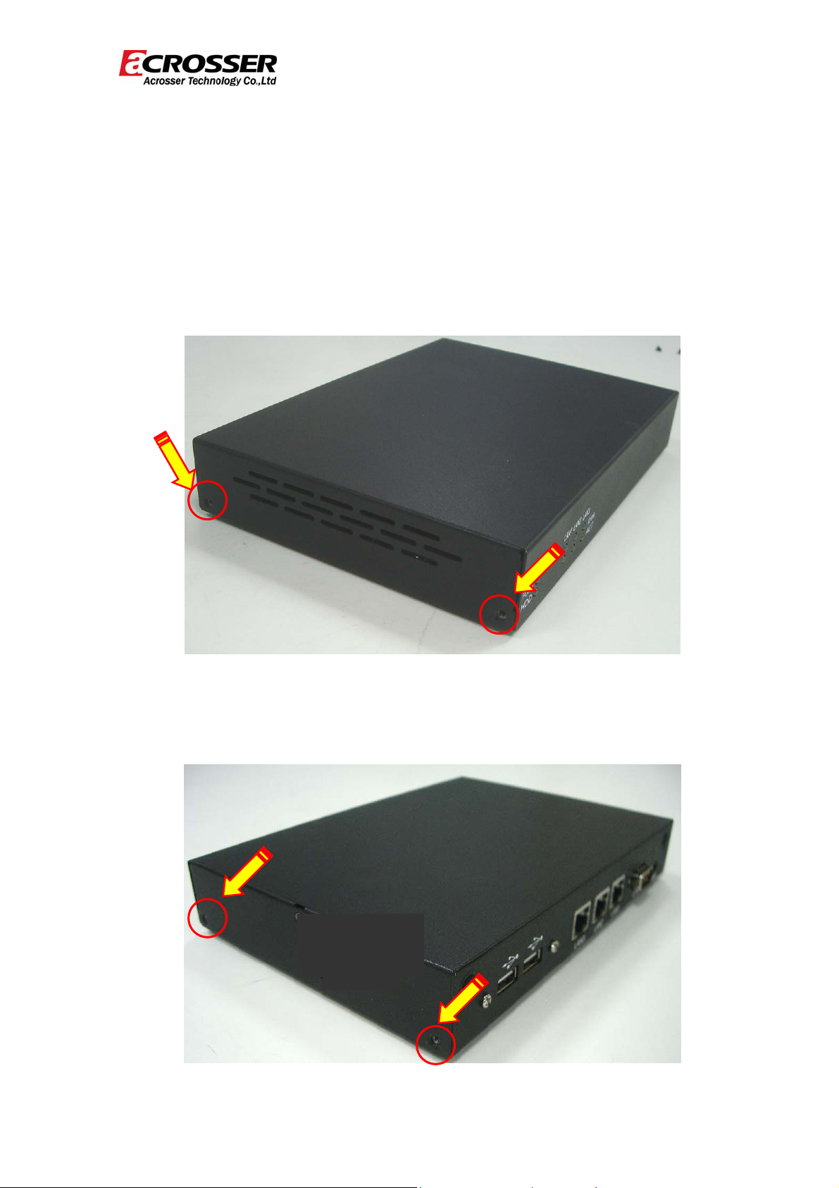
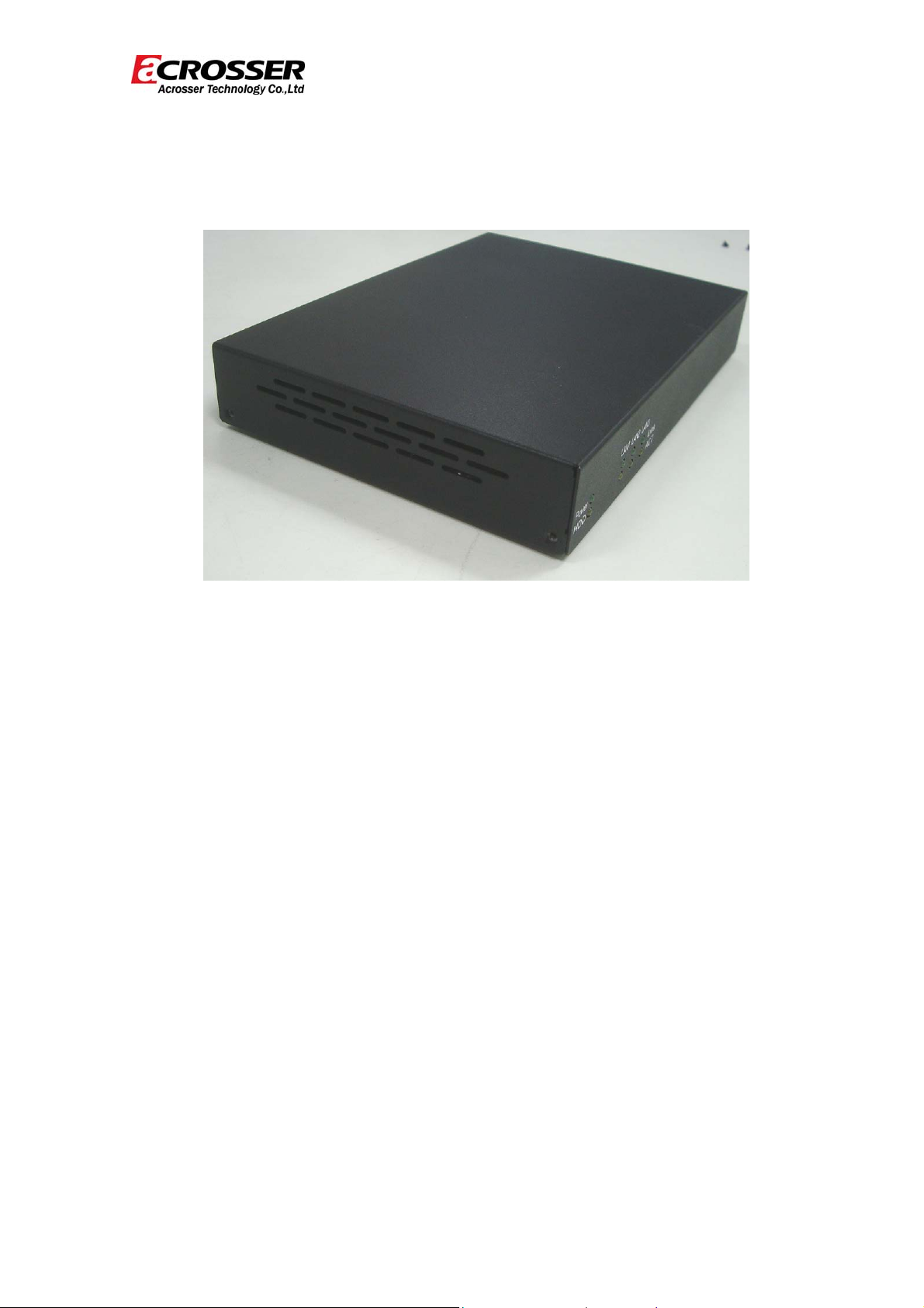
2 Procedures of Assembly/Disassembly
2.1 Installing the CF card.
Follow this guide to install CF card step-by-step.
1. Unfasten four screws of chassis top cover and open it.
(a) Unscrew left side screws of chassis top cover
Unscrew
(b) Unscrew right side screws of chassis top cover
Unscrew
Unscrew
Unscrew
8
Page 9
(c) Open chassis top cover
Revision: 1.0
2. Insert CF card into the CF socket.
9
Page 10
Revision: 1.0
3. Finally, follow step1 to assemble the top cover and fasten it with four screws.
10
Page 11

Revision: 1.0
AR-B8601 Board Guide
1 Introduction
Acrosser Microbox Networking device AR-N8601 is a small, cost-effetive and
entry-level UTM (Unified Threat Management) hard ware, which is suitable for small
office. Base on VIA CN700 with ULV Eden 500MHz CPU, the AR-N8601 general
very low heat. We also put a quiet Fan to keep the low noise which will not cause
uncomfortable voice. By three 10/100 Lans, the AR-N8601 is sufficient for the small
business security hardware solution
1.1 Package Contents
Check if the following items are included in the package:
Quick Manual.
AR-B8601.
1 x Software Utility CD.
11
Page 12
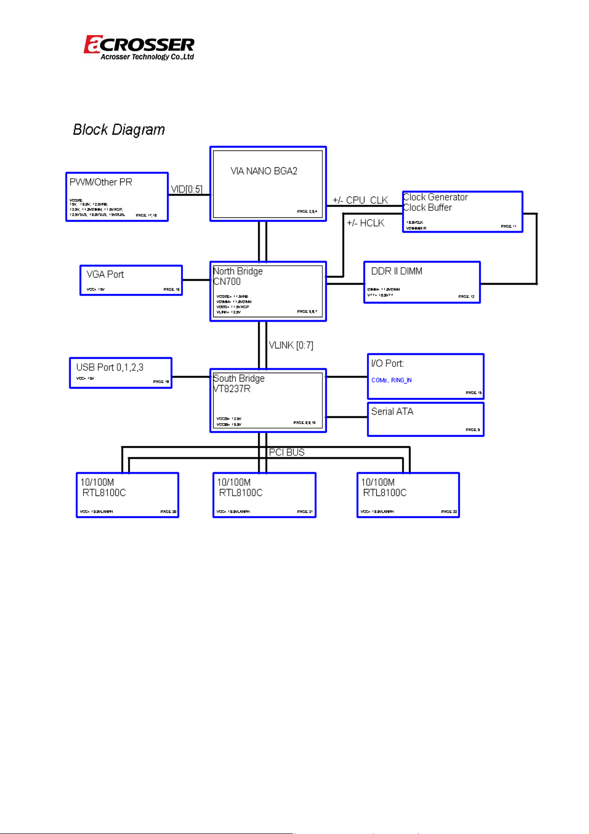
1.2 Block Diagram
Revision: 1.0
12
Page 13

Revision: 1.0
2 H/W Information
This chapter describes the installation of AR-B8601. First, it shows the function
diagram and the layout of AR-B8601. It then describes the unpacking information,
as well as the jumpers and connectors setting for the AR-B8601 configuration.
2.1 Locations (Top side)
13
Page 14

Revision: 1.0
2.2 Connectors and Jumpers Location
2.2.1 Locations (Top side)
LED1: POWER,HDD LED Ethernet RJ-45 (LAN1)
LED2, LED3, LED4: LAN LED
USB Connector1 Ethernet RJ-45 (LAN3)
USB Connector2 VGA Connector
DDR2 Memory Slot Serial Port
PCI Slot (3.3 Volt) Power Jack (12V Input)
JP1: CMOS Jumper Panel Connector
SATA Power Connector GPIO Connector
SATA Connector Compact Flash Connector
FAN Connector
14
Ethernet RJ-45 (LAN2)
Page 15

Revision: 1.0
2.3 Jumpers and Connectors Pin define
1. LED1: POWER HDD LED 2. LED2,LED3,LED4:
3. USB Connector1
LAN LED
PIN SIGNAL PIN SIGNAL
+5V
LDE1 Description
UP
DOWN
POWER
HDD
LED Description
UP
DOWN
LINK
ACTS
1
USB2-
3
USB2+
5
GND
7
GND
9
4. USB Connector2 5. DDR2 Memory Slot 6. PCI Slot (3.3 Volt)
PIN SIGNAL PIN SIGNAL
+5V
2
USB3-
4
USB3+
6
GND
8
GND
10
+5V
1
USB0-
3
USB0+
5
GND
7
GND
9
+5V
2
USB1-
4
USB1+
6
GND
8
GND
10
SODIMM Memory
Slot
7. JP1: CMOS Jumper 8. SATA Power
Connector
SET SIGNAL
+12V
JP1 Description
1-2
2-3
NORMAL(default)
RESET COMS
1
GND
2
+3.3V
3
+5V
4
PCI Slot (3.3 Volt)
9. SATA Connector
PIN SIGNAL PIN SIGNAL
GND
1
3
5
GND
7
TX-
RX+
2
4
6
TX+
GND
RX-
15
Page 16

Revision: 1.0
10. Keyboard / Mouse
Connector
PIN Description
GND
1
FAN VCC
2
3
SENSE
11./12./13. Ethernet RJ-45
(LAN1/LAN2/LAN3)
PIN SIGNAL PIN SIGNAL
TX+
1
TX-
2
RX+
3
N/C
4
N/C
5
RX-
6
N/C
7
N/C
8
14. VGA Connector
PIN Description
1
2
3
4
5
6
7
SYNCHRON (VS)
CLOCK (CLK)
8
HORIZONTAL
9
SYNCHRON (HS)
DATA (SDATA)
10
15. Serial Port 16. Power Jack (12V Input) 17. Panel Connector
RED (R)
Ground
GREEN (G)
Ground
BLUE (B)
Ground
VERTICAL
PIN Description
DATA CARRIER
1
DETECT (DCD)
RECEIVE DATA
2
3
4
5
6
7
8
9
18. GPIO Connector 19. Compact Flash Connector
PIN SIGNAL PIN SIGNAL
1
3
5
7
(RXD)
TRANSMIT DATA
(TXD)
DATA TERMINAL
READY (DTR)
GROUND
DATA SET READY
(DSR)
REQUEST TO
SENTD (RTS)
CLEAR TO SEND
(CTS)
RING INDICATOR
(RI)
VCC
GPIO0
GPIO1
GPIO2
2
4
6
8
GND
GPIO4
GPIO5
GPIO6
Power Jack (12V Input)
Compact Flash Connector
SET SIGNAL
1-2
3-4
5-6
7-8
POWER LED
RSET
POWER
BUTTOM
OPEN: ATX
MODE
CLOSE: AT
MODE
(default)
9
GPIO3
10
GPIO7
16
Page 17

Revision: 1.0
3 WATCHDOG, GPIO PROGRAMMING
GPIO Sample Code
//===========================================================================
// Turbo C++ Version 3.0 Copyright(c) 1990, 1992 by Borland International,Inc.
//===========================================================================
// Describe : GPIO10~GPIO17 Test utility for W83697HF.
// Date : 06/26/2009
// Author : Willy
//===========================================================================
#include <conio.h>
#include <stdio.h>
void Show_Help();
void Show_Fail();
void Show_Pass();
//===========================================================================
// Main procedure
//===========================================================================
int main(int argc)
{
unsigned char IO_PORT_BASE=0x2E; // DATA_PORT = IO_PORT_BASE + 1;
unsigned char data;
int result=0;
if ( argc > 1 )
{ Show_Help(); return 1; }
clrscr();
textcolor(WHITE);
gotoxy(1, 1);
cprintf("<>==========================================================================<>");
gotoxy(1, 2); cprintf("|| W83697HF GPIO Test Utility v1.0 Acrosser Technology Co., Ltd. ||");
gotoxy(1, 3);
cprintf("<>==========================================================================<>");
gotoxy(1, 4);
cprintf("<>==========================================================================<>");
17
Page 18

Revision: 1.0
gotoxy(1, 5); cprintf("|| Model Name : ||");
gotoxy(1, 6); cprintf("|| SIO IO Base : ||");
gotoxy(1, 7);
cprintf("<>==========================================================================<>");
// Show Got Parameter Informat
textcolor(LIGHTGRAY);
gotoxy(18,6); cprintf("%X",IO_PORT_BASE);
// Enter W83697HF Config
outportb(IO_PORT_BASE,0x87);
outportb(IO_PORT_BASE,0x87);
// Set Multi-function Pins to GPIO
outportb(IO_PORT_BASE,0x29);
outportb(IO_PORT_BASE+1,(inportb(IO_PORT_BASE+1) | 0x80));
// Select GPIO Port device
outportb(IO_PORT_BASE,0x07);
outportb(IO_PORT_BASE+1,0x07);
// Set GPIO Port Active
outportb(IO_PORT_BASE,0x30);
outportb(IO_PORT_BASE+1,0x01);
// Set W83697HF GPIO10~13 to Output, GPIO14~GPIO17 to Input
outportb(IO_PORT_BASE,0xF0);
outportb(IO_PORT_BASE+1,0xF0);
// Set W83697HF GPIO10~13 to High
outportb(IO_PORT_BASE,0xF1);
outportb(IO_PORT_BASE+1,0x0F);
// Read W83697HF GPIO14~17 Status, if not High error.
data=inportb(IO_PORT_BASE+1)&0xF0;
if(data!=0xF0)
result=1;
// Set W83697HF GPIO10~13 to Low
outportb(IO_PORT_BASE,0xF1);
18
Page 19

Revision: 1.0
outportb(IO_PORT_BASE+1,0x00);
// Read W83697HF GPIO14~17 Status, if not Low error.
data=inportb(IO_PORT_BASE+1)&0xF0;
if(data!=0x00)
result=1;
// Set W83697HF GPIO10~13 to input, GPIO14~GPIO17 to Output
outportb(IO_PORT_BASE,0xF0);
outportb(IO_PORT_BASE+1,0x0F);
// Set W83697HF GPIO14~17 to High
outportb(IO_PORT_BASE,0xF1);
outportb(IO_PORT_BASE+1,0xF0);
// Read W83697HF GPIO10~13 Status, if not High error.
data=inportb(IO_PORT_BASE+1)&0x0F;
if(data!=0x0F)
result=1;
// Set W83697HF GPIO14~17 to Low
outportb(IO_PORT_BASE,0xF1);
outportb(IO_PORT_BASE+1,0x00);
// Read W83697HF GPIO14~17 Status, if not Low error.
data=inportb(IO_PORT_BASE+1)&0x0F;
if(data!=0x00)
result=1;
// Exit W83697HF Config
outportb(IO_PORT_BASE,0xAA);
if(result)
Show_Fail();
else
Show_Pass();
return result;
}
19
Page 20

Revision: 1.0
//===========================================================================
// Function : Show_Help()
// Input : -
// Change : -
// Return : -
// Description : Show Title string.
//===========================================================================
void Show_Help()
{
clrscr();
printf("GPIO Test utility for W83697HF\n\n");
printf("VCC GND\n");
pr
intf("GPIO0
printf("GPIO1
printf("GPIO2
printf("GPIO3
}
迋迋迋
GPIO4\n");
迋迋迋
GPIO5\n");
迋迋迋
GPIO6\n");
迋迋迋
GPIO7\n");
20
Page 21

Revision: 1.0
WATCHDOG TIMER
//===========================================================================
// Describe : W83697HF WatchDog timer test
// Date : 08/12/2004
// Author : Willy
//===========================================================================
//===========================================================================
// Language include files
//===========================================================================
#include <conio.h>
#include <stdlib.h>
#include <stdio.h>
typedef unsigned char BYTE;
typedef unsigned short int WORD;
typedef unsigned long int DWORD;
//===========================================================================
// Normal procedure
//===========================================================================
void Show_Title()
{
clrscr();
printf("WatchDog Test for W83697HF\n");
printf("1. WDT.EXE 10 s ==--> 10 seconds to reset.\n");
printf("2. WDT.EXE 20 m ==--> 20 minutes to reset.\n");
}
//===========================================================================
// Main procedure
//===========================================================================
int main(int argc, char *argv[])
{
char Time_Format;
BYTE IO_Port_Address=0x2E;
BYTE Time=10; // Default is 10
BYTE Format=0x01; // Default is 0x01 = Seconds
21
Page 22

if ( argc != 3 )
{ Show_Title(); return 1; }
clrscr();
textcolor(YELLOW+BLINK);
Time=atoi(argv[1]);
Time_Format=argv[2][0];
if(Time_Format=='m' || Time_Format=='M')
Format=0x05; // Minutes
if(Time_Format=='s' || Time_Format=='S')
Revision: 1.0
Format=0x01; // Seconds
// Set Watchdog
outportb(IO_Port_Address,0x87); // (EFER) Extended Functions Enable Register
outportb(IO_Port_Address,0x87);
outportb(IO_Port_Address,0x29); // Point to Global Reg.
outportb(IO_Port_Address+1,0x20); // Select Multi-Function pin, (Bit[5,6]=01 Watchdog Function)
outportb(IO_Port_Address,0x07); // Point to Logical Device Number Reg.
outportb(IO_Port_Address+1,0x08); // Select logical device 8, (Watchdog Function)
outportb(IO_Port_Address,0x30); // Device Active register
outportb(IO_Port_Address+1,0x01);
outportb(IO_Port_Address,0xF3); // Select Watchdog count mode seconds or minutes
outportb(IO_Port_Address+1,Format); // Default is second
outportb(IO_Port_Address,0xF4); // Set Watchdog Timer Value
outportb(IO_Port_Address+1,Time); // 0x00 to disable, max 0xFF
while(1)
{
outportb(IO_Port_Address,0xF4); // Read Watchdog Timer Value
Time=inportb(IO_Port_Address+1);
22
Page 23

Revision: 1.0
gotoxy(20,10);
if(Time_Format=='m' || Time_Format=='M')
cprintf(">>> After %d Minutes will reset the system. <<<",Time);
if(Time_Format=='s' || Time_Format=='S')
cprintf(">>> After %d Second will reset the system. <<<",Time);
}
return 0;
}
23
Page 24

Revision: 1.0
4 BIOS Setting
This chapter describes the BIOS menu displays and explains how to perform
common tasks needed to get the system up and running. It also gives detailed
explanation of the elements found in each of the BIOS menus. The following topics
are covered:
Main Setup
Advanced Chipset Setup
Power Setup
PnP/PCI Setup
Peripherals Setup
PC Health Setup
Boot Setup
Exit Setup
24
Page 25

Revision: 1.0
4.1 Main Setup
Once you enter the Award BIOS™ CMOS Setup Utility, the Main Menu will
appear on the screen. Use the arrow keys to highlight the item and then use the <Pg
Up> <Pg Dn> keys to select the desired value in each item.
Note: The control keys are listed at the bottom of the menu. If you need any help with the
item fields, you can press the <F1> key, and the relevant information will be displayed.
Option Choice Description
Set the system date. Note that the ‘Day’
Date Setup
N/A
automatically changes when you set the
date.
Time Setup
N/A Set the system time.
The onboard PCI IDE connectors provide 1
channel for connecting up to 2 IDE hard disks
IDE Channel 0
N/A
or other devices. The first is “Master” and the
Master/Slave
second is “Slave”, the BIOS will auto-detect
the IDE type.
All Errors,
Select the situation in which you want the
Halt On
No Errors,
BIOS to stop the POST process and notify
25
Page 26

Revision: 1.0
All but keyboard. you.
26
Page 27

4.2 Advanced Chipset Setup
Revision: 1.0
Option Choice Description
This category speeds up the Power On Self Test (POST)
Quick Power
On Self Test
Enabled
Disabled
after you have powered on the computer. If it is set to
Enabled, the BIOS will shorten or skip some check items
during POST.
Full Screen
Logo Show
Enabled
Disabled
Select Enabled to show the full screen logo if you have
an add-in BIOS.
Enabled
APIC Mode
Select Enable or Disable the APIC Mode.
Disabled
Select Enabled if your system contains a Universal
USB Keyboard
Enabled
Serial Bus (USB) controller and you have a USB
Support
Disabled
keyboard.
Initialize the onboard video display before initializing any
INIT Display
Enabled
other display device on the system.Thus the onboard
First
Disabled
display becomes the primary display.
VGA Share
Memory Size
16M
Select VGA Share Memory Size.
32M
64M
27
Page 28

Revision: 1.0
Console
Redirection
Baud Rate
Agent after
boot
[Enabled] for user who want to remote control the
Enabled
system via serial port.
Disabled
9600
19200
The baud rate of remote control machine should the
38400
same as the system for communication.
57600
115200
Enabled
Keep Agent running after OS boot
Disabled
28
Page 29

4.3 Power Setup
Revision: 1.0
Option Choice Description
ACPI Function
Enabled ACPI System Support
29
Page 30

4.4 PnP/PCI Setup
Revision: 1.0
Option Choice Description
Reset Configuration
Data
Normally, you leave this field
Disabled. Select Enabled to reset the
Extended System Configuration Data
(ESCD) when you exit Setup. This
Enabled
may be necessary if you have
Disabled
installed a new add-on and the
system reconfiguration has caused
such a serious conflict that the
operating system can not boot.
The Award Plug and Play BIOS has
the capacity to automatically configure
all of the boot and Plug and Play
Resources Controlled By
Auto (ESCD)
Manual
30
compatible devices. However, this
capability means absolutely nothing
unless you are using a Plug and Play
operating system such as Windows
95 or higher. If you set this field to
Page 31

Revision: 1.0
“Manual”, you may choose specific
resources by entering each of the
submenus.
When resources are controlled
manually, assign a type to each
IRQ Resources
N/A
system interrupt, depending on the
type of the device that uses the
interrupt.
31
Page 32

4.5 Peripherals Setup
Revision: 1.0
Option Choice Description
Onboard Serial Port 1
Onboard Serial Port 2
Onboard Serial Port 3
Onboard Serial Port 4
Onboard Serial Port 5
Onboard Serial Port 6
USB Controller
Serial Port 1: 3F8 / IRQ4
Serial Port 2: 2F8 / IRQ3
Select an address and the
Serial Port 3: 3E8 / IRQ11
corresponding interrupt for
Serial Port 4: 2E8 / IRQ10
each serial port.
Serial Port 5: 2A8 / IRQ7
Serial Port 6: 288 / IRQ5
Select Enabled if your
system contains a
Enabled
Universal Serial Bus (USB)
Disabled
controller and you have
USB peripherals.
Select Enabled if your
USB 2.0 Controller
Enabled
system contains a
Universal Serial Bus (USB)
Disabled
2.0 controller and you have
USB peripherals.
32
Page 33

Revision: 1.0
The integrated peripheral
controller contains an IDE
On Chip IDE DEVICE
Enabled
Disabled
interface with support for
two IDE channels. Select
Enabled to activate each
channel separately.
33
Page 34

Revision: 1.0
4.6 PC Health Setup
This section shows the parameters for determining the PC Health Status. These
parameters include temperatures, fan speeds, and voltages.
34
Page 35

4.7 Boot Setup
Revision: 1.0
Option Choice Description
First / Second / Third
Boot Device/Other Boot
Device
LAN Boot Select
Hard Disk Boot Priority
Hard Disk
CDROM
USB-FDD
USB-CDROM
LAN
Disabled
Enabled
Disabled
N/A
The BIOS attempts to load
the operating system from
the devices in the selected
sequence.
These fields allow the
system to search for an OS
from LAN.
These fields set the Boot
Priority for each Hard Disk.
35
Page 36

4.8 Exit Setup
Revision: 1.0
Option Choice Description
Save & Exit Setup
Press <Enter> on this item
to confirm:
Save to CMOS and EXIT
(Y/N)? Y
When you press <Enter>
on this item, you will see a
Press “Y” to store the
selections made in the menus
in CMOS – a special section of
the memory that stays on after
you turn your system off. The
next time you boot your
computer, the BIOS configures
your system according to the
setup selections stored in
CMOS. After saving the values,
the system will restart.
Press ‘Y’ to load the default
Load Optimized
Defaults
confirmation dialog box
with a message like this:
Load Optimized Defaults
(Y/N)? N
36
values that are factory-set for
optimal-performance system
operations.
Page 37

Revision: 1.0
This allows you to exit Setup
Exit Without Saving
Set Password
Press <Enter> on this item
to confirm:
Quit without saving
(Y/N)? Y
Press <Enter> on this item
to confirm:
ENTER PASSWORD:
without storing any changes in
CMOS. The previous selections
remain in effect. This will exit
the Setup utility and restart your
computer.
When a password has been
enabled, you will be prompted
to enter your password every
time you try to enter Setup.
This prevents unauthorized
persons from changing any part
of your system configuration.
Type the password, up to eight
characters in length, and press
<Enter>. The password typed now
will clear any previous password
from the CMOS memory. You will
be asked to confirm the password.
Type the password again and
press <Enter>. You may also
press <Esc> to abort the selection
and not enter a password.
To disable a password, just press
<Enter> when you are prompted
to enter the password. A message
will confirm that the password will
be disabled. Once the password is
disabled, the system will boot and
you can enter Setup freely.
37
 Loading...