

Page 1

AR-B8601 User Manual
AR-B8601 Board
VIA EDEN , VGA, LAN, DDR2
PCI, COM, 4 USB
User Manual
Manual Rev. : 1.2
Book Number: AR-B8601-2010.11.22
1
Page 2

Revision
M
Version Date Author Description
1.0 2009.09.23 Cody Release
AR-B8601 User Manual
1.1 2010.06.30 Cody
1.2 2010.11.22 Cody
1.Modify item description with
INIT Display First
2.Add used ACPI Suspend Type
3.
odify item description with
Onboard Serial Port 1
1. Modify connector table
description with Panel Connector.
2
Page 3

AR-B8601 User Manual
Copyright 2008
All Rights Reserved.
Manual’s first edition:
For the purpose of improving reliability, design and function, the information in this document is
subject to change without prior notice and does not represent a commitment on the part of the
manufacturer.
No event will the manufacturer be liable for direct, indirect, special, incidental, or consequential
damages arising out of the use or inability to use the product or documentation, even if advised of
the possibility of such damages.
This document contains proprietary information protected by copyright. All rights are reserved. No
part of this Manual may be reproduced by any mechanical, electronic, or other means in any form
without prior written permission of the manufacturer.
Trademarks
AR-B8601 is a registered trademarks of Acrosser; IBM PC is a registered trademark of the
International Business Machines Corporation; Pentium is a registered trademark of Intel
Technologies Inc; Award is a registered trademark of Award Software International Inc; other
product names mentioned herein are used for identification purposes only and may be trademarks
and/or registered trademarks of their respective companies.
3
Page 4

AR-B8601 User Manual
Table of Contents
1 Introduction ..........................................................................................5
1.1 Specifications................................................................................................... 6
1.2 Package Contents............................................................................................7
1.3 Block Diagram .................................................................................................. 8
2 H/W Information.................................................................................... 9
2.1 Locations (Top side)......................................................................................... 9
2.2 Connector and Jumper Setting....................................................................... 10
2.3 Connector and Jumper Setting Table............................................................. 11
3 WATCHDOG, GPIO PROGRAMMING................................................13
4 BIOS Setting .......................................................................................20
4.1 Main Setup...................................................................................................... 21
4.2 Advanced Chipset Setup................................................................................22
4.3 Power Setup................................................................................................... 24
4.4 PnP/PCI Setup................................................................................................ 25
4.5 Peripherals Setup........................................................................................... 27
4.6 PC Health Setup.............................................................................................28
4.7 Boot Setup......................................................................................................29
4.8 Exit Setup ....................................................................................................... 30
4
Page 5

AR-B8601 User Manual
1
Acrosser's Microbox Networking device AR-N8601 is a small, cost-effetive and entry-level UTM
(Unified Threat Management) hard ware, which is suitable for small office. The Board of this
microbox is AR-B8601. Base on VIA CN700 with ULV Eden 500MHz CPU, the AR-B8601
general very low heat. By three 10/100 Lans, the AR-B8601 is sufficient for the small business
security hardware solution.
INTRODUCTION
5
Page 6

1.1 Specifications
VIA EDEN ULV 500 CPU.
VIA CN700+8237R plus Chipsets.
DDRII memory support (533MHz).
3 x 10/100LAN RTL8100C.
CF socket, SATA x 1, SATA power, USB x 4.
Console, VGA (pinhead).
Support PXE boot from LAN.
Compact size.
AR-B8601 User Manual
6
Page 7

1.2 Package Contents
Check if the following items are included in the package :
Quick Manual.
AR-B8601.
1 x Software Utility CD.
AR-B8601 User Manual
7
Page 8
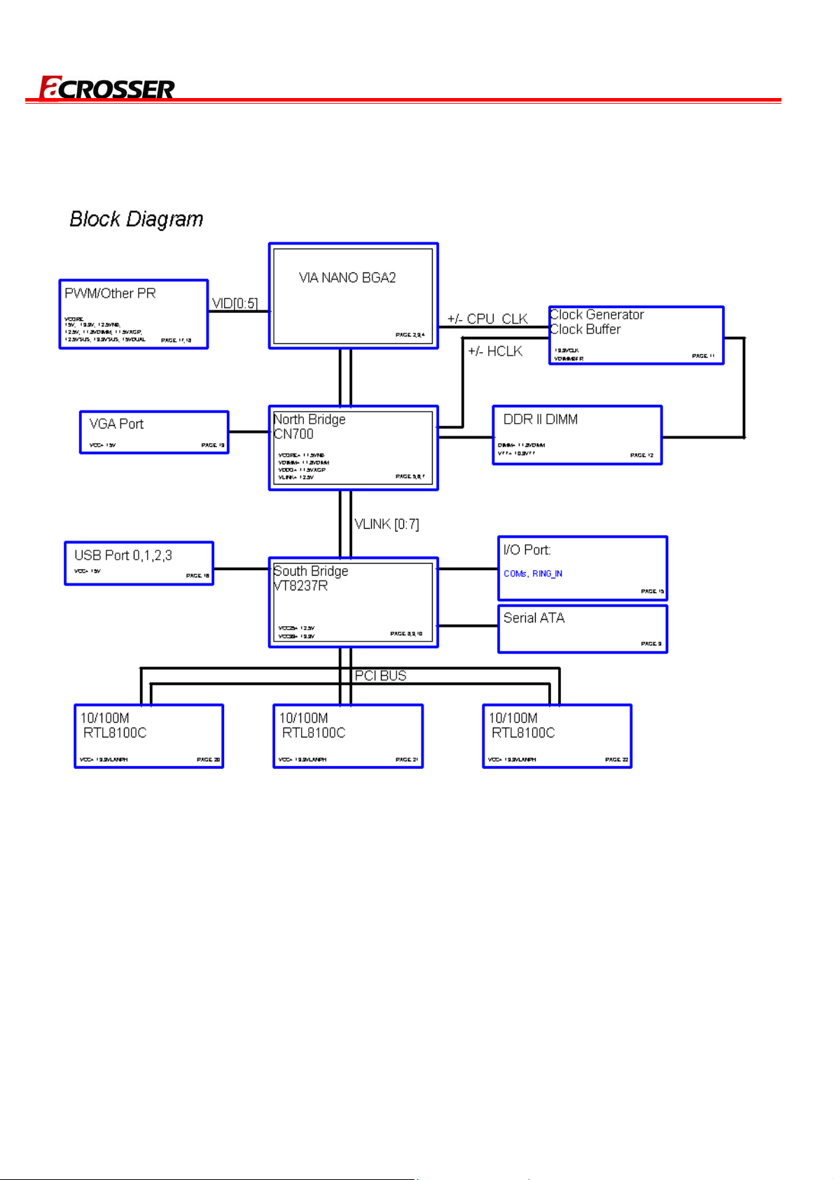
1.3 Block Diagram
AR-B8601 User Manual
8
Page 9
AR-B8601 User Manual
2
This chapter describes the installation of AR-B8601. At first, it shows the function diagram and the
layout of AR-B8601. It then describes the unpacking information which you should read carefully,
as well as the jumper/switch settings for the AR-B8601 configuration.
H/W INFORMATION
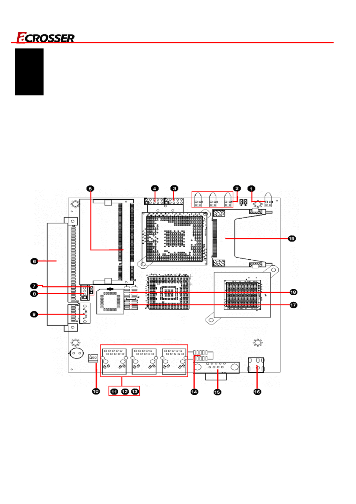
2.1 Locations (Top side)
9
Page 10
2.2 Connector and Jumper Setting
AR-B8601 User Manual
POWER,HDD LED Ethernet RJ-45
LAN LED Ethernet RJ-45
USB Connector1 Ethernet RJ-45
USB Connector2 VGA Connector
DDR2 Memory Slot Serial Port
PCI Slot (3.3 Volt) (OPTION) Power Jack (12V Input)
JP1: CMOS Jumper Panel Connector
SATA Power Connector GPIO Connector
SATA Connector Compact Flash Connector
FAN Connector
10
Page 11

AR-B8601 User Manual
2.3 Connector and Jumper Setting Table
2.3.1 POWER HDD LED 2.3.2 LAN LED 2.3.3 USB Connector1
PIN SIGNAL PIN SIGNAL
LDE1 Description
UP
DOWN
POWER
HDD
+5V
LED Description
LINK
ACTS
UP
DOWN
1
USB2-
3
USB2+
5
GND
7
GND
9
+5V
2
USB3-
4
USB3+
6
GND
8
GND
10
2.3.4 USB Connector2 2.3.5 DDR2 Memory Slot 2.3.6 PCI Slot (3.3 Volt)
PIN SIGNAL PIN SIGNAL
+5V
1
USB0-
3
USB0+
5
GND
7
+5V
2
USB1-
4
USB1+
6
GND
8
SODIMM Memory Slot
PCI Slot (3.3 Volt)
(OPTION)
GND
9
10
GND
2.3.7 JP1: CMOS Jumper 2.3.8 SATA Power Connector 2.3.9 SATA Connector
SET SIGNAL
JP1 Description
NORMAL(default)
1-2
2-3
RESET COMS
1
2
3
4
+12V
GND
+3.3V
+5V
PIN SIGNAL PIN SIGNAL
GND
1
TX-
3
RX+
5
GND
7
11
TX+
2
GND
4
RX-
6
Page 12

AR-B8601 User Manual
2.3.10 FAN Connector
2.3.14 VGA Connector
RJ-45 (LAN1/LAN2/LAN3)
2.3.11/2.3.12/2.3.13 Ethernet
PIN Description
RED (R)
Ground
GREEN (G)
Ground
BLUE (B)
Ground
VERTICAL
SYNCHRON (VS)
CLOCK (CLK)
HORIZONTAL
SYNCHRON (HS)
DATA (SDATA)
PIN Description
1
2
3
GND
FAN VCC
SENSE
PIN SIGNAL PIN SIGNAL
TX+
1
TX-
2
RX+
3
N/C
4
N/C
5
RX-
6
N/C
7
N/C
8
1
2
3
4
5
6
7
8
9
10
2.3.15 Serial Port 2.3.16 Power Jack (12V Input) 2.3.17 Panel Connector
PIN Description
DATA CARRIER
1
DETECT (DCD)
RECEIVE DATA
2
3
4
5
6
7
8
9
2.3.18 GPIO Connector 2.3.19 Compact Flash Connector
PIN SIGNAL PIN SIGNAL
1
3
5
7
(RXD)
TRANSMIT DATA
(TXD)
DATA TERMINAL
READY (DTR)
GROUND
DATA SET READY
(DSR)
REQUEST TO
SENTD (RTS)
CLEAR TO SEND
(CTS)
RING INDICATOR
(RI)
VCC
GPIO0
GPIO1
GPIO2
2
4
6
8
GND
GPIO4
GPIO5
GPIO6
Power Jack (12V Input)
Compact Flash Connector
SET SIGNAL
1-2
3-4
5-6
7-8
POWER LED
RSET
POWER BUTTOM
CLOSE: AT MODE
GPIO3
9
10
GPIO7
12
Page 13

AR-B8601 User Manual
3
GPIO ,WATCHDOG PROGRAMMING
GPIO Sample Code
//===========================================================================
// Turbo C++ Version 3.0 Copyright(c) 1990, 1992 by Borland International,Inc.
//===========================================================================
// Describe : GPIO10~GPIO17 Test utility for W83697HF.
// Date : 06/26/2009
// Author : Willy
//===========================================================================
#include <conio.h>
#include <stdio.h>
void Show_Help();
void Show_Fail();
void Show_Pass();
//===========================================================================
// Main procedure
//===========================================================================
int main(int argc)
{
unsigned char IO_PORT_BASE=0x2E; // DATA_PORT = IO_PORT_BASE + 1;
unsigned char data;
int result=0;
if ( argc > 1 )
{ Show_Help(); return 1; }
clrscr();
textcolor(WHITE);
gotoxy(1, 1); cprintf("<>==========================================================================<>");
gotoxy(1, 2); cprintf("|| W83697HF GPIO Test Utility v1.0 Acrosser Technology Co., Ltd. ||");
gotoxy(1, 3); cprintf("<>==========================================================================<>");
13
Page 14

AR-B8601 User Manual
gotoxy(1, 4); cprintf("<>==========================================================================<>");
gotoxy(1, 5); cprintf("|| Model Name : ||");
gotoxy(1, 6); cprintf("|| SIO IO Base : ||");
gotoxy(1, 7); cprintf("<>==========================================================================<>");
// Show Got Parameter Informat
textcolor(LIGHTGRAY);
gotoxy(18,6); cprintf("%X",IO_PORT_BASE);
// Enter W83697HF Config
outportb(IO_PORT_BASE,0x87);
outportb(IO_PORT_BASE,0x87);
// Set Multi-function Pins to GPIO
outportb(IO_PORT_BASE,0x29);
outportb(IO_PORT_BASE+1,(inportb(IO_PORT_BASE+1) | 0x80));
// Select GPIO Port device
outportb(IO_PORT_BASE,0x07);
outportb(IO_PORT_BASE+1,0x07);
// Set GPIO Port Active
outportb(IO_PORT_BASE,0x30);
outportb(IO_PORT_BASE+1,0x01);
// Set W83697HF GPIO10~13 to Output, GPIO14~GPIO17 to Input
outportb(IO_PORT_BASE,0xF0);
outportb(IO_PORT_BASE+1,0xF0);
// Set W83697HF GPIO10~13 to High
outportb(IO_PORT_BASE,0xF1);
outportb(IO_PORT_BASE+1,0x0F);
// Read W83697HF GPIO14~17 Status, if not High error.
data=inportb(IO_PORT_BASE+1)&0xF0;
if(data!=0xF0)
result=1;
// Set W83697HF GPIO10~13 to Low
14
Page 15

outportb(IO_PORT_BASE,0xF1);
outportb(IO_PORT_BASE+1,0x00);
// Read W83697HF GPIO14~17 Status, if not Low error.
data=inportb(IO_PORT_BASE+1)&0xF0;
if(data!=0x00)
result=1;
// Set W83697HF GPIO10~13 to input, GPIO14~GPIO17 to Output
outportb(IO_PORT_BASE,0xF0);
outportb(IO_PORT_BASE+1,0x0F);
// Set W83697HF GPIO14~17 to High
outportb(IO_PORT_BASE,0xF1);
outportb(IO_PORT_BASE+1,0xF0);
AR-B8601 User Manual
// Read W83697HF GPIO10~13 Status, if not High error.
data=inportb(IO_PORT_BASE+1)&0x0F;
if(data!=0x0F)
result=1;
// Set W83697HF GPIO14~17 to Low
outportb(IO_PORT_BASE,0xF1);
outportb(IO_PORT_BASE+1,0x00);
// Read W83697HF GPIO14~17 Status, if not Low error.
data=inportb(IO_PORT_BASE+1)&0x0F;
if(data!=0x00)
result=1;
// Exit W83697HF Config
outportb(IO_PORT_BASE,0xAA);
if(result)
Show_Fail();
else
Show_Pass();
return result;
}
15
Page 16

//===========================================================================
// Function : Show_Help()
// Input : -
// Change : -
// Return : -
// Description : Show Title string.
//===========================================================================
void Show_Help()
{
clrscr();
printf("GPIO Test utility for W83697HF\n\n");
AR-B8601 User Manual
printf("VCC GND\n");
printf("
printf("GPIO1
printf("GPIO2
printf("GPIO3
}
GPIO0
迋迋迋
迋迋迋
迋迋迋
迋迋迋
GPIO4\n");
GPIO5\n");
GPIO6\n");
GPIO7\n");
16
Page 17

WATCHDOG TIMER Sample Code
//===========================================================================
// Describe : W83697HF WatchDog timer test
// Date : 08/12/2004
// Author : Willy
//===========================================================================
//===========================================================================
// Language include files
//===========================================================================
#include <conio.h>
#include <stdlib.h>
#include <stdio.h>
AR-B8601 User Manual
typedef unsigned char BYTE;
typedef unsigned short int WORD;
typedef unsigned long int DWORD;
//===========================================================================
// Normal procedure
//===========================================================================
void Show_Title()
{
clrscr();
printf("WatchDog Test for W83697HF\n");
printf("1. WDT.EXE 10 s ==--> 10 seconds to reset.\n");
printf("2. WDT.EXE 20 m ==--> 20 minutes to reset.\n");
}
//===========================================================================
// Main procedure
//===========================================================================
int main(int argc, char *argv[])
{
char Time_Format;
BYTE IO_Port_Address=0x2E;
BYTE Time=10; // Default is 10
17
Page 18

BYTE Format=0x01; // Default is 0x01 = Seconds
if ( argc != 3 )
{ Show_Title(); return 1; }
clrscr();
textcolor(YELLOW+BLINK);
Time=atoi(argv[1]);
Time_Format=argv[2][0];
if(Time_Format=='m' || Time_Format=='M')
Format=0x05; // Minutes
AR-B8601 User Manual
if(Time_Format=='s' || Time_Format=='S')
Format=0x01; // Seconds
// Set Watchdog
outportb(IO_Port_Address,0x87); // (EFER) Extended Functions Enable Register
outportb(IO_Port_Address,0x87);
outportb(IO_Port_Address,0x29); // Point to Global Reg.
outportb(IO_Port_Address+1,0x20); // Select Multi-Function pin, (Bit[5,6]=01 Watchdog Function)
outportb(IO_Port_Address,0x07); // Point to Logical Device Number Reg.
outportb(IO_Port_Address+1,0x08); // Select logical device 8, (Watchdog Function)
outportb(IO_Port_Address,0x30); // Device Active register
outportb(IO_Port_Address+1,0x01);
outportb(IO_Port_Address,0xF3); // Select Watchdog count mode seconds or minutes
outportb(IO_Port_Address+1,Format); // Default is second
outportb(IO_Port_Address,0xF4); // Set Watchdog Timer Value
outportb(IO_Port_Address+1,Time); // 0x00 to disable, max 0xFF
while(1)
{
18
Page 19

outportb(IO_Port_Address,0xF4); // Read Watchdog Timer Value
Time=inportb(IO_Port_Address+1);
gotoxy(20,10);
if(Time_Format=='m' || Time_Format=='M')
cprintf(">>> After %d Minutes will reset the system. <<<",Time);
if(Time_Format=='s' || Time_Format=='S')
cprintf(">>> After %d Second will reset the system. <<<",Time);
}
return 0;
}
AR-B8601 User Manual
19
Page 20

AR-B8601 User Manual
4
This chapter describes the BIOS menu displays and explains how to perform common tasks
needed to get the system up and running. It also gives detailed explanation of the elements found
in each of the BIOS menus. The following topics are covered :
Main Setup
Advanced Chipset Setup
Power Setup
PnP/PCI Setup
Peripherals Setup
PC Health Setup
Boot Setup
Exit Setup
BIOS SETTING
20
Page 21

AR-B8601 User Manual
4.1 Main Setup
Once you enter the Award BIOS™ CMOS Setup Utility, the Main Menu will appear on the screen.
Use the arrow keys to highlight the item and then use the <Pg Up> <Pg Dn> keys to select the
desired value in each item.
Note: The control keys are listed at the bottom of the menu. If you need any help with the item fields, you
can press the <F1> key, and the relevant information will be displayed.
Option Choice Description
Set the system date. Note that the ‘Day’
Date Setup
N/A
automatically changes when you set the
date.
Time Setup
N/A Set the system time.
The onboard PCI IDE connectors provide 1
channel for connecting up to 2 IDE hard
IDE Channel 0
N/A
disks or other devices. The first is “Master”
Master/Slave
and the second is “Slave”, the BIOS will
auto-detect the IDE type.
All Errors,
Select the situation in which you want the
Halt On
No Errors,
All but keyboard.
BIOS to stop the POST process and notify
you.
21
Page 22

4.2 Advanced Chipset Setup
AR-B8601 User Manual
Option Choice Description
This category speeds up the Power On
Quick Power On Self Test
Enabled
Disabled
Enabled
Full Screen Logo Show
Disabled
Enabled
APIC Mode
Disabled
Enabled
USB Keyboard Support
Disabled
Self Test (POST) after you have powered
on the computer. If it is set to Enabled, the
BIOS will shorten or skip some check
items during POST.
Select Enabled to show the full screen
logo if you have an add-in BIOS.
Select Enable or Disable the APIC Mode.
Select Enabled if your system contains a
Universal Serial Bus (USB) controller and
you have a USB keyboard.
Initialize the onboard video display before
INIT Display First
PCI Slot
Onboard
initializing any other display device on the
system.Thus the onboard display
becomes the primary display.
22
Page 23

AR-B8601 User Manual
16M
Select VGA Share Memory Size.
VGA Share Memory Size
32M
64M
Enabled
[Enabled] for user who want to remote
Console Redirection
Disabled
control the system via serial port.
9600
Baud Rate
19200
38400
57600
The baud rate of remote control machine
should the same as the system for
communication.
115200
Enabled
Agent after boot
Keep Agent running after OS boot
Disabled
23
Page 24

4.3 Power Setup
AR-B8601 User Manual
Option Choice Description
ACPI Function
ACPI Suspend Type
Enabled
Disabled
S1(POS)
ACPI System Support
To decide which ACPI suspend
mode to use.
24
Page 25

4.4 PnP/PCI Setup
AR-B8601 User Manual
Option Choice Description
Normally, you leave this field
Disabled. Select Enabled to reset
the Extended System Configuration
Reset Configuration
Data
Enabled
Disabled
Data (ESCD) when you exit Setup.
This may be necessary if you have
installed a new add-on and the
system reconfiguration has caused
such a serious conflict that the
operating system can not boot.
25
Page 26

AR-B8601 User Manual
The Award Plug and Play BIOS has
the capacity to automatically
configure all of the boot and Plug
and Play compatible devices.
However, this capability means
Resources Controlled
By
Auto (ESCD)
Manual
absolutely nothing unless you are
using a Plug and Play operating
system such as Windows 95 or
higher. If you set this field to
“Manual”, you may choose specific
resources by entering each of the
submenus.
When resources are controlled
manually, assign a type to each
IRQ Resources
N/A
system interrupt, depending on the
type of the device that uses the
interrupt.
26
Page 27

4.5 Peripherals Setup
AR-B8601 User Manual
Option Choice Description
Disabled
Onboard Serial Port
3F8 / IRQ4
2F8 / IRQ3
1
3E8 / IRQ4
2E8 / IRQ3
Enabled
USB Controller
Disabled
27
Select an address and the
corresponding interrupt for each
serial port.
Select Enabled if your system
contains a Universal Serial Bus
(USB) controller and you have
USB peripherals.
Page 28

AR-B8601 User Manual
Select Enabled if your system
USB 2.0 Controller
On chip IDE DEVICE
4.6 PC Health Setup
Enabled
Disabled
Enabled
Disabled
contains a Universal Serial Bus
(USB) 2.0 controller and you
have USB peripherals.
The integrated peripheral
controller contains an IDE
interface with support for two IDE
channels. Select Enabled to
activate each channel
separately.
This section shows the parameters for determining the PC Health Status. These parameters
include temperatures, fan speeds, and voltages.
28
Page 29
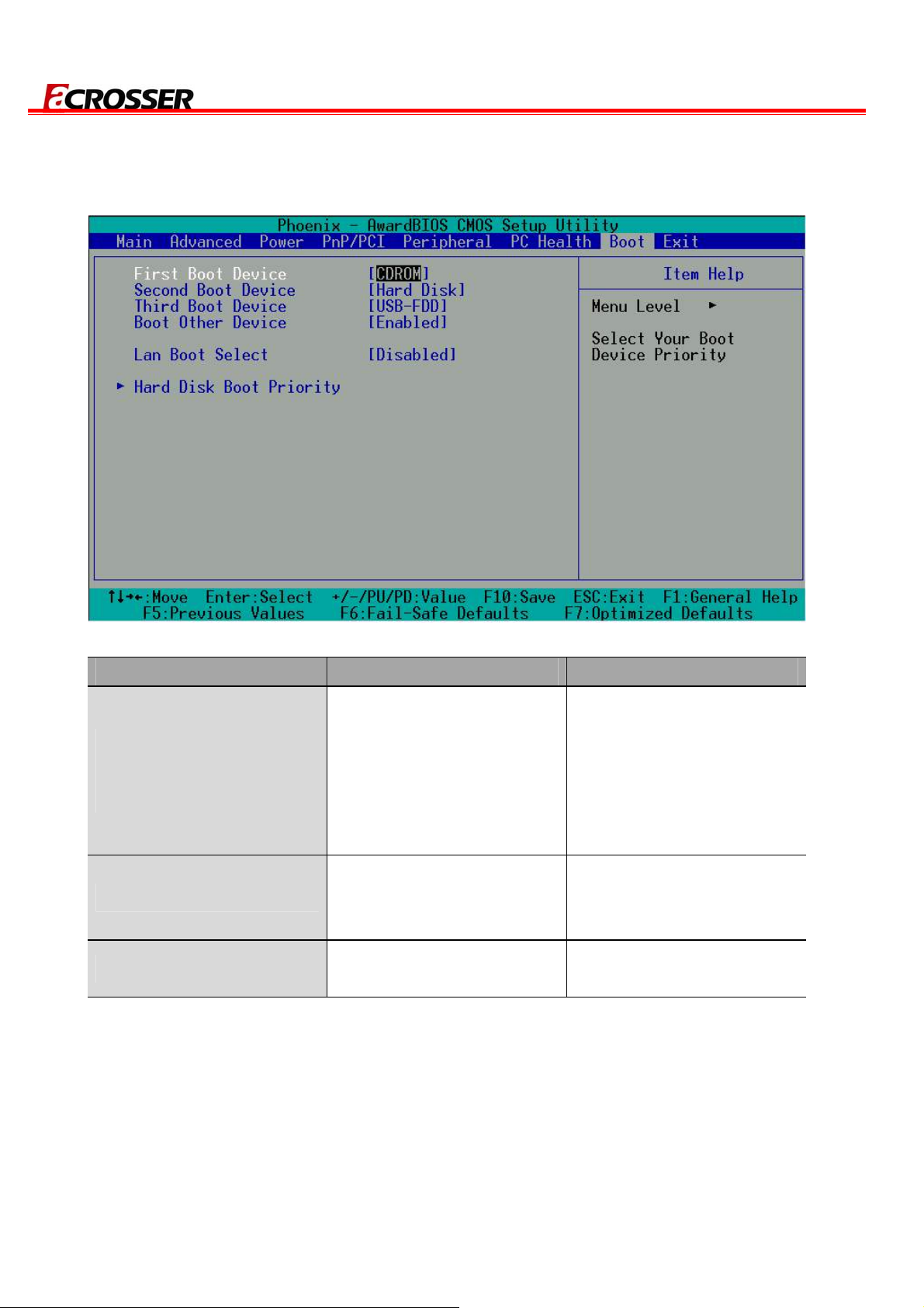
4.7 Boot Setup
AR-B8601 User Manual
Option Choice Description
Hard Disk
First / Second / Third
Boot Device/Other Boot
Device
LAN Boot Select
Hard Disk Boot Priority
CDROM
USB-FDD
USB-CDROM
LAN
Disabled
Enabled
Disabled
N/A
The BIOS attempts to load
the operating system from
the devices in the selected
sequence.
These fields allow the
system to search for an
OS from LAN.
These fields set the Boot
Priority for each Hard Disk.
29
Page 30
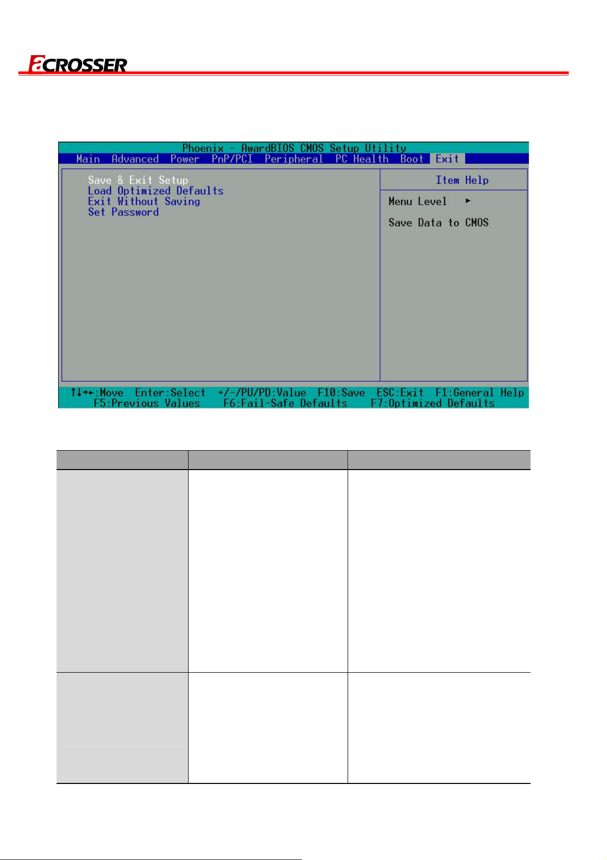
4.8 Exit Setup
AR-B8601 User Manual
Option Choice Description
Press “Y” to store the
selections made in the menus
in CMOS – a special section of
Press <Enter> on this item
to confirm:
Save & Exit Setup
Save to CMOS and EXIT
(Y/N)? Y
When you press <Enter>
on this item, you will see a
the memory that stays on after
you turn your system off. The
next time you boot your
computer, the BIOS configures
your system according to the
setup selections stored in
CMOS. After saving the values,
the system will restart.
Press ‘Y’ to load the default
Load Optimized
Defaults
confirmation dialog box
with a message like this:
Load Optimized Defaults
(Y/N)? N
30
values that are factory-set for
optimal-performance system
operations.
Page 31

AR-B8601 User Manual
This allows you to exit Setup
Exit Without Saving
Set Password
Press <Enter> on this item
to confirm:
Quit without saving
(Y/N)? Y
Press <Enter> on this item
to confirm:
ENTER PASSWORD:
without storing any changes in
CMOS. The previous selections
remain in effect. This will exit
the Setup utility and restart your
computer.
When a password has been
enabled, you will be prompted
to enter your password every
time you try to enter Setup. This
prevents unauthorized persons
from changing any part of your
system configuration.
Type the password, up to eight
characters in length, and press
<Enter>. The password typed now
will clear any previous password
from the CMOS memory. You will
be asked to confirm the password.
Type the password again and
press <Enter>. You may also
press <Esc> to abort the selection
and not enter a password.
To disable a password, just press
<Enter> when you are prompted
to enter the password. A message
will confirm that the password will
be disabled. Once the password is
disabled, the system will boot and
you can enter Setup freely.
31
 Loading...