

Page 1

Revision :1.0
AR-ES5495
Installation Guide
Revision Description Date
1.0 Release 2009/11/25
1
Page 2

Revision :1.0
Contents
Introduction to AR-ES5495………………………………………………….……… 3
1
1.1 Specifications…………………………………………………………………… 3
1.2 Packing List……………………………………………………………………… 3
1.3 System Dissection………………………………………………………………. 4
2
1.3-1 Dimensions………………………………………………………………… 4
1.3-2 Front Panel………………………………………………………………… 4
1.3-3 I/O Bracket………………………………………………………………… 5
1.4 System Configuration
Procedure of Assembly/Disassembly……………………………………………… 6
2.1 Installation 3.5“ HDD…………………………………………………………… 6
2.2 Installation Memory Module……………………………………………………. 10
2.3 Installation IDE-DOM…………………………………………………………… 12
……………………………………………………………………… 5
2
Page 3

Revision :1.0
1 Introduction to AR-ES5495
AR-ES5495 is an Intel Atom N270 + 945GSE chipset based platform; it provides fanless,
low power consumption, tiny size, easy installation and light weight for you. It is design for
low cost communication device; user can use it to build up simply internal communication
environment.
1.1 Specifications
Item Description
System AR-ES5495
CPU Board AR-B5495
System Dimensions 230×215×65 (mm)
1.2 Packing List
Description Q’ty
AR-ES5495 1
1GB DDRII 667MHz SDRAM (pre-installed) 1
Utility CD 1
AR-ES5495 system manual 1
LPT Cable 1
SATA Cable 2
SATA Power convert cable 1
44 pin IDE Cable 1
COM Port Cable w/bracket 1
3
Page 4

1.3 System Dissection
1.3-1 Dimensions
65mm
Revision :1.0
230mm
1.3-2 Front Panel
2 x USB
HDD Led(red)
Power Led(green)
Power Button
Reset Botton
4
Page 5

1.3-3 I/O Bracket
V
Revision :1.0
Parallel Port
PS2 Mouse
PS2 Keyboard
GA1 Port
1.4 System Configuration
AR-ES5495 Case IDE DOM
HDD Bracket
Serial Port
LAN Port x 2
USB Port x 4
Line-out
Microphone
Power Inlet
Serial Port
Power Supply
RAM
AR-B5495 Board
5
Page 6

Revision :1.0
2 Procedure of Assembly/Disassembly
2.1 HDD Installation
The following instructions guide you to install 3.5” HDD
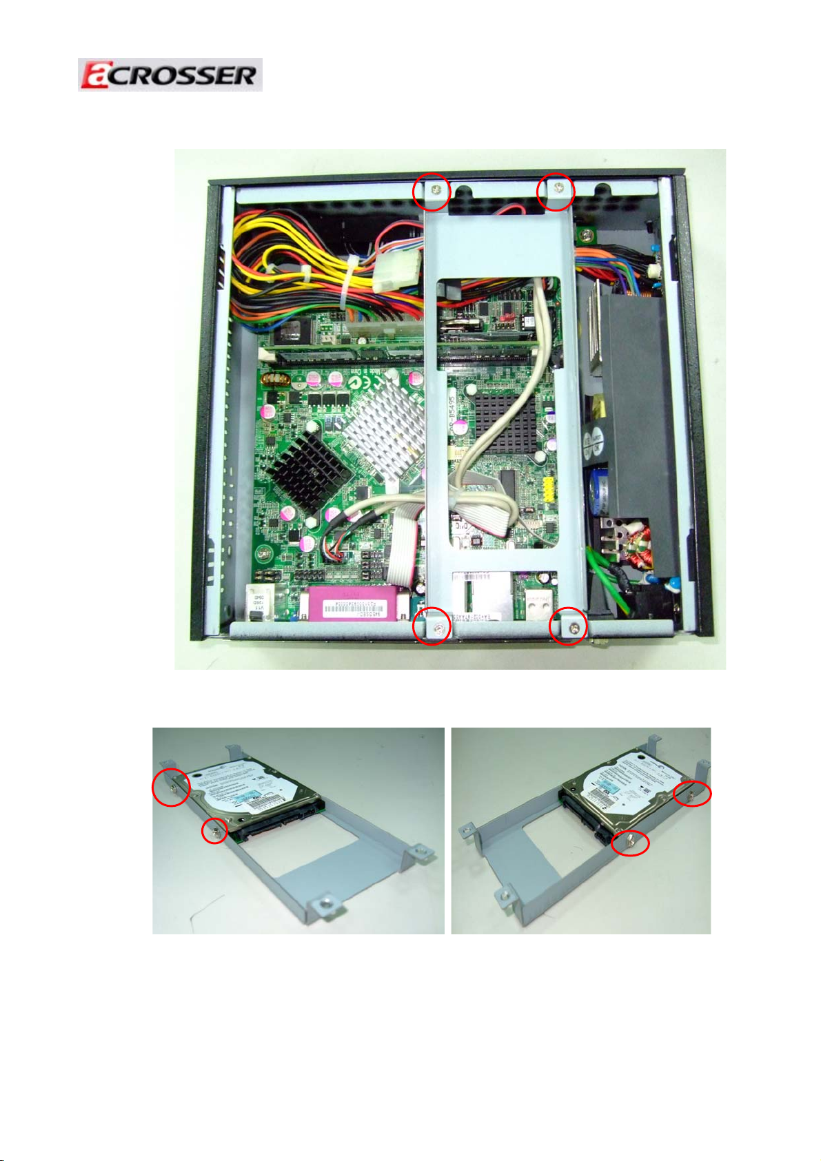
1. Unscrew two screws to unfasten the top cover.
Unscrew Unscrew
2. Take off the top cover.
1
2
6
Page 7
Revision :1.0
3. Unscrew screws of the HDD-Bracket and take off the HDD-Bracket.
4. Put the 3.5” HDD on the HDD-Bracket and fix it by four screws.
7
Page 8

Revision :1.0
5. Plug in the SATA cable and SATA power cable to the 3.5”HDD.
6. Then connect the SATA cable and SATA power cable to the AR-B5495 board.
SATA cable
SATA power cable
8
Page 9

Revision :1.0
7. Put the HDD-Bracket back to chassis and fix it.
Screw
Screw
8. Fixed the top cover with the chassis.
Screw
Screw
9
Page 10
Revision :1.0
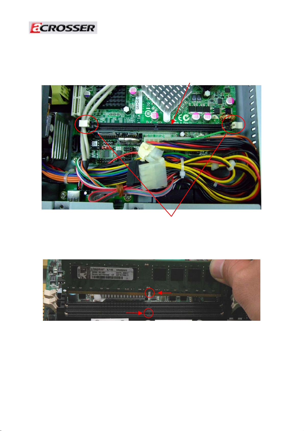
2.2 Installation Memory Module
1. Please follow the steps above to remove the top cover.
2. Open the two latch of memory slot.
RAM module
Latch
2. Align the memory cutout with the memory module slot notch.
Cut out
Notch
10
Page 11
Revision :1.0
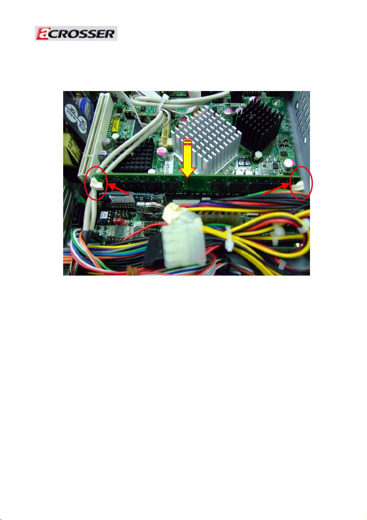
3. Slide the memory into the memory module.
PUSH
Check that the latches are closed, and
memory module is firmly installed.
11
Page 12

Revision :1.0
2.3 Installation IDE-DOM
1. The IDE-DOM slot please look at below photo.
IDE-DOM slot
2. Install IDE-DOM on below position.
First pin
12
 Loading...