

Page 1

AR-B6003 Board
User Manual
1
Page 2

Copyright
All Rights Reserved.
Manual’s first edition:
For the purpose of improving reliability, design and function, the
information in this document is subject to change without prior notice and does
not represent a commitment on the part of the manufacturer.
In no event will the manufacturer be liable for direct, indirect, special,
incidental, or consequential damages arising out of the use or inability to use
the product or documentation, even if advised of the possibility of such
damages.
This document contains proprietary information protected by copyright. All
rights are reserved. No part of this Manual may be reproduced by any
mechanical, electronic, or other means in any form without prior written
permission of the manufacturer.
Trademarks
AR-B6003 is a registered trademarks of Acrosser; IBM PC is a registered
trademark of the International Business Machines Corporation; Pentium is a
registered trademark of Intel Technologies Inc; Award is a registered
trademark of Award Software International Inc; other product names
mentioned herein are used for identification purposes only and may be
trademarks and/or registered trademarks of their respective companies.
2
Page 3

Table of Contents
Chapter 1 Introduction...................................................................................................4
1.1 Specifications...................................................................................................4
1.2 Package Contents.............................................................................................5
1.3 Block Diagram.................................................................................................5
Chapter 2 H/W Information...........................................................................................6
2.1 Mainboard illustration (Top Side)....................................................................6
2.2 Locations of IO ports & Jumper Setting Definition (Top Side).......................8
Chapter 3 BIOS Settings..............................................................................................17
3.1 Main Setup.....................................................................................................18
3.2 Advanced Chipset Setup................................................................................21
3.3 PnP/PCI Setup................................................................................................23
3.4 Peripherals Setup ...........................................................................................24
3.5 PC Health Setup.............................................................................................27
3.6 Boot setup ......................................................................................................28
3.7 Exit Setup.......................................................................................................30
Chapter 4 Function Description...................................................................................32
4.1 DC Power input connection...........................................................................32
4.2 Digital Inputs .................................................................................................33
4.3 Digital Outputs...............................................................................................34
4.4 Watchdog Timer.............................................................................................35
4.5 RS-232 Ports..................................................................................................35
4.6 Serial ATA (SATA).........................................................................................37
4.7 USB................................................................................................................37
Chapter 5 Driver And Utility Installation ....................................................................38
5.1 Driver CD Interface Introduction...................................................................38
5.2 Windows XP 32bit Driver Installation...........................................................46
5.3 Windows 7 32/64bit Driver Installation.........................................................48
Chapter 6 Software Installation and Programming Guide...........................................51
6.1 Introduction....................................................................................................51
6.2 File Descriptions............................................................................................52
6.3 API List and Descriptions..............................................................................53
6.4 Enable TESTSIGNING on Windows 7 X64 system .....................................56
3
Page 4

Chapter 1 Introduction
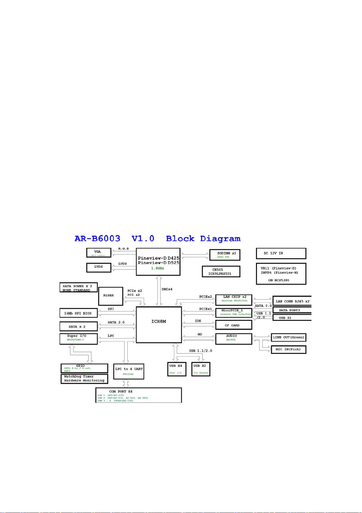
AR-B6003 is an embedded SBC that is designed for rugged environment.
Without compromise the performance, it equipped with the most advanced
ATOM D525 (dual cores) or D425 (single core) CPU and up to 4GB of DDR3
memory. Customers can select suitable CPU and memory size to get the
best performance/price ratio. AR-B6003 has diverse physical interface for
different peripheral, e.g. VGA port, LVDS pin header, 4 * USB 2.0 ports, 2 *
USB 2.0 pin header, 4 * COM port, 2 * GB LAN ports, 2 * SATA ports, CF slot,
and Realtek audio input/output port. It is also equipped a dedicated bus
which can expand PCI and PCI express slots. Users can purchase Acrosser
riser card to satisfy their today and tomorrow needs.
1.1 Specifications
CPU Intel Dual Core ATOM D525 or Single Core ATOM D425
Chipset Intel ICH8M Chipset
Memory 2 x DDR3 SO-DIMM, up to 4GB memory
Ethernet 2 x RJ45 10/100/1000Mbps LAN ports
Serial Port 3 x RS-232 (DB9) & 1 x RS-232/422/485 (DB9)
USB 6 x USB 2.0 (4 x external port, 2 x pin header)
GPIO 8 bit digital I/O (4 x IN & 4 x OUT)
CF 1 x external CF socket
SATA 1 x 2.5” HDD bay, SATA II interface x 2
Video VGA (DB15) & 18 bit LVDS (pin header)
Audio Line-out & MIC connector
Mini-PCIe 1 x mini-PCIe slot for expansion
Expansion 1 x dedicated bus for PCI & PCIe slot
AR-RS20 --- 2 x PCIe slot
AR-RS21 --- 1 x PCI slot & 1 x PCIe slot
OS support Win XP (32 bit), Win 7 (32/64 bit), Fedora 14 (32/64 bit),
Ubuntu 10 (32/64 bit)
4
Page 5
1.2 Package Contents
Check if the following items are included in the package.
Quick Manual
AR-B6003 board
1 x Software Utility CD
1.3 Block Diagram
5
Page 6

Chapter 2 H/W Information
This chapter describes the installation of AR-B6003. At first, it shows the
Function diagram and the layout of AR-B6003. It then describes the
unpacking information which you should read carefully, as well as the
jumper/switch settings for the AR-B6003 configuration.
2.1 Mainboard illustration (Top Side)
6
Page 7
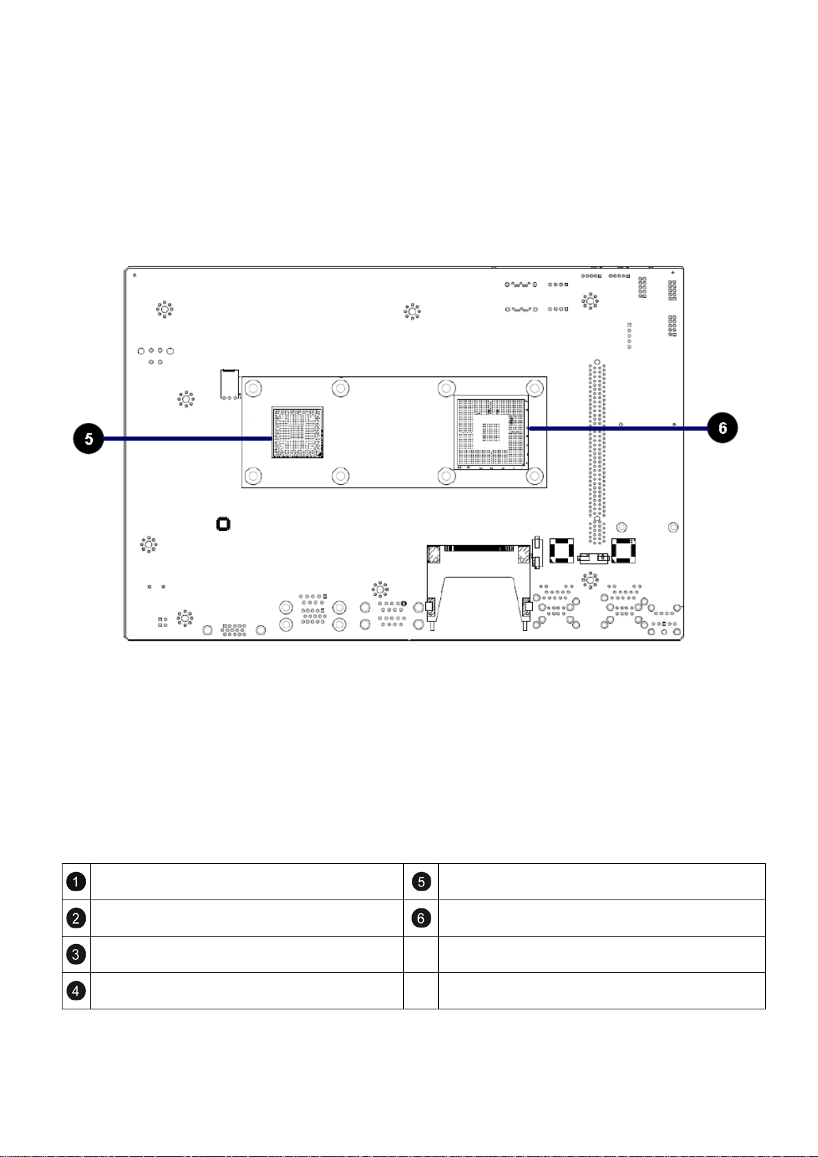
Mainboard illustration (Bottom Side)
BH1
System RTC battery socket
PCIE_R1
PCI-E & PCI riser card socket
CN_DIMM2
204-Pin DDR3 Socket
CN_DIMM1
204-Pin DDR3 Socket
In tel Atom Pineview D425/D525 CPU
Intel ICH8M
7
Page 8

2.2 Locations of IO ports & Jumper Setting Definition (Top Side)
8
Page 9

Locations Of IO Ports & Jumper Setting
Definition (Bottom Side)
9
Page 10
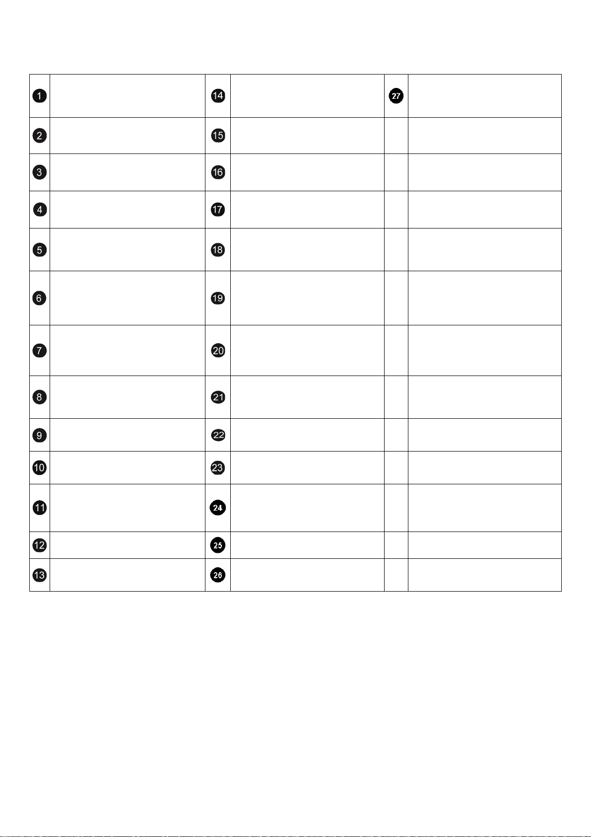
FPIO1
ATX Power on/off & Reset switch
button connector.
SIM1
SIM card Holder
MINIPCIE1
Mini-PCI Express Card connector
AUDIO1
Line Out & Mic in phone jack.
CN9
RJ45 & USB 2 ports (USB0,USB1)
Connector
CN8
RJ45 & USB 2 ports
(USB2,USB3)Connector
SW3
For CF CARD power select and Power
Mode select.
LED1
2 in 1 LED for Power & HDD LED.
PWR1
Connector for 0932V power board
CN_RS232_1
Pin Header for COM2 use RS-232
function
CN_RS422_485_1
Pin Header for COM2 use
RS-422/485 function
LVDS1
LVDS connector
LCDPWR1
For LCD Power connector
CN4
ATX12V Power Supply input
Connector
CF1
CF CARD SOCKET
.
COM3_COM4
D-SUB 9 pin for COM3,COM4 RS232
connector
SW2
For RS-422, RS-485 function select.
SW4
For RS-422,RS-485 function select.
GPIO_COM1
D-SUB 9 pin COM1 for RS-232,
D-SUB 15 pin for External GPIO
connector.
SW5
For RS-422, RS-485 function select.
VGA1
D-sub 15 pin VGA connecter
CCMOS1
CMOS Memory Clearing Header
SATA1, SATA2
SATA device connector #1, #2
SATA_PWR1, SATA_PWR2
For SATA Power Connector #1, #2
FP_USB1,FP_USB2
Internal USB4, USB5 connector.
BH1
CR2032 Battery Hold Connector.
CPUFAN1
CPU FAN connector.
10
Page 11
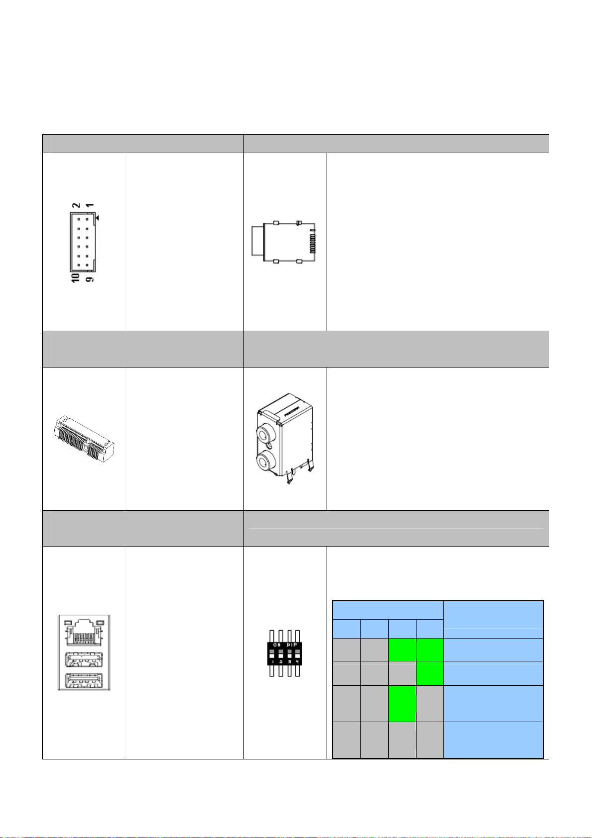
2.2.1 Connectors and Jumper settings
1. FPIO1 2. SIM1 Connector
FPIO1 Connector
Pin1-2 ATX Power on/off
switch button
Pin5-6 System Reset
switch button
3. MINIPCIE1 ( Mini-PCIe
Connector )
Mini-PCIe x1
Connector
4. AUDIO1
SIM Card Holder
Connects to 3.5G Cell phone SIM Card.
Audio Jack
Lime: Line Out
Pink: Mic in
5,6. CN8,CN9 (RJ45 x1& USB Port
x2)
RJ45 Ethernet
Connector with 2 ports
of External USB
Connector
7. SW3 (CF card power select and Power Mode select)
SW3 DIP Switch
(Default:Key1 OFF; Key2 OFF, Key3 ON; Key4
ON)
11
SW3
1 2 3 4
OFF OFF ON ON 9427B power board,AT mode
OFF OFF OFF ON 0932V power boar d,AT mode
OFF OFF ON OFF
OFF OFF OFF OFF
Function
9427B power board,ATX
mode
0932V power board,ATX
mode
Page 12
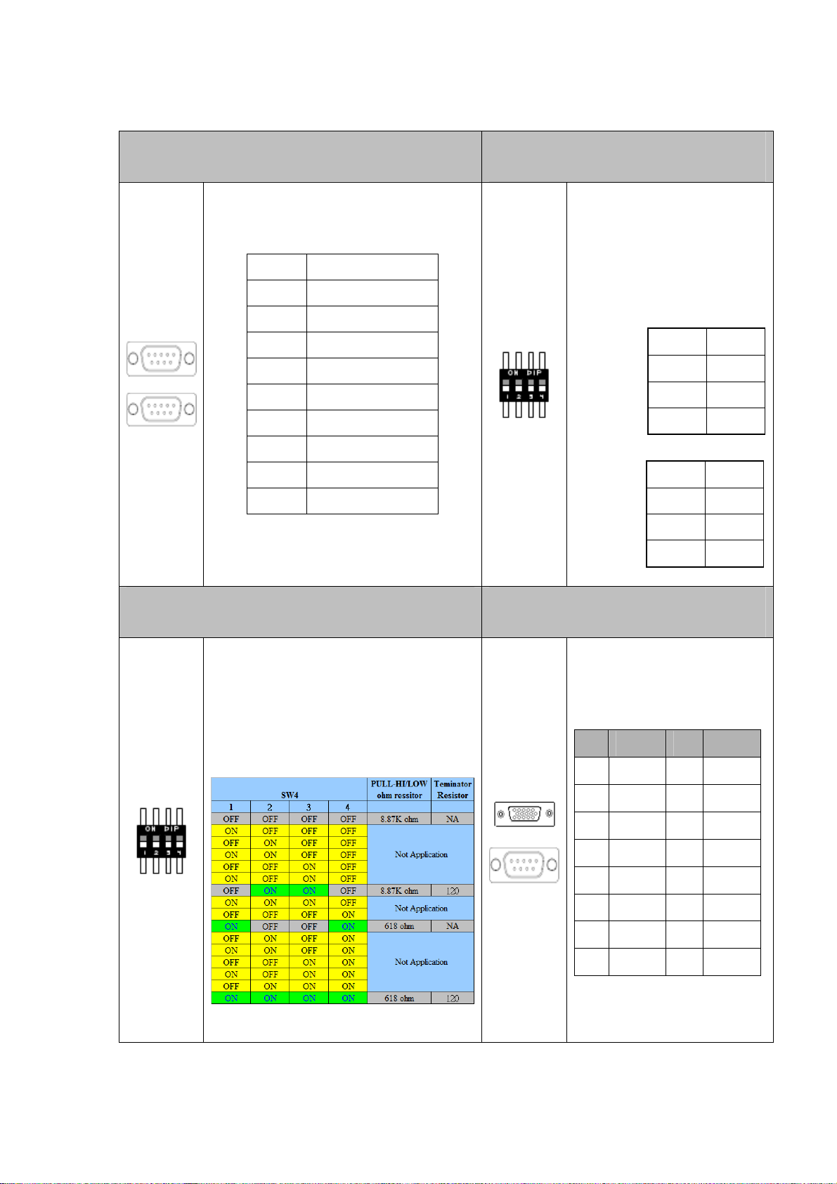
8. COM3_COM4 ( for COM3,COM4 use ) 9. SW2 ( RS-422,RS-485 function
select )
SW2, DIP Switch
For RS-422,RS-485 Function
Pin SIGNAL
1 DCD
2 SIN
3 SOUT
4 DTR
5 GND
6 DSR
7 RTS
8 CTS
9 RI
10. SW4 ( RS-422/485 TX Terminator resistor
selection )
select(Default: All OFF For
RS-232)
RS-422 setting:
1
2
3
4 ON
OFF
ON
OFF
RS-485 setting:
1
2
3
4 ON
ON
ON
OFF
1 1 GPIO_COM1 (For COM1 RS-232,
External GPIO control)
SW4 DIP Switch
For RS-422/485 TX Terminator resistor
selection)
(Default: all OFF)
PIN SIGNAL PIN SIGNAL
1
3
5
7
9
11
13
15
GPO2
VCC12A
GPIO Pin Define:
GPO0
GND
GND
GND
GPI4
GPI6
2
4
6
8
10
12
14
GPO1
GPO3
GND
GND
GND
GPI5
GPI7
12
Page 13

12, SW5 (RS-422 RX terminator resistor
13. VGA1 (D-SUB 15 pin
selection)
SW5 DIP Switch
For RS-422 RX Terminator resistor
selection)
(Default: all OFF)
Connector)
VGA1
D-SUB 15 pin For CRT
Monitor
14. LED1 15 PWR1 (For 0932V power
board use only Connector)
Green: Power ON LED.
Yellow: HDD LED
Pin 1 GND
Pin 2 PSON
Pin 3 5VSB
13
Page 14

16. CN_RS232_1
17. CN_RS422_485_1
(For COM2 Function select).
CN_RS232_1: For RS-232 Function
Pin SIGNAL
1 DSR
2 DCD
3 RTS
18. LVDS1 (30 pin DF 13 Connector).
4 SIN
5 CTS
6 SOUT
7 RI
8 DTR
9 NC
10 GND
CN_RS422_485_1: For RS-422,RS-485
Function
Pin SIGNAL
1 NC
2 485_422_TX+
3 NC
4 485_422_TX-
LVDS1:
30 pin DF13 connector
5 422_RX26 NC
7 422_RX2+
8 NC
9 NC
10 GND
14
Page 15

19.LCDPWR1 (LCD Power Connector) 20. CN4 (ATX12V Power Input)
Pin 1 VCC
Pin 2 NC
Pin 3 GND
21. CCMOS1. 22. SATA1, SATA2 (SATA device connector
#1 and #2).
To connect SATA device:
1.Attach either end of the signal cable
to the SATA connector on
motherboard.
Attach the other end to the SATA
device.
2. Attach the SATA power cable to the
SATA device and connect the other
end from the power supply.
15
Page 16

23. SATA_PWR1, SATA_PWR2 24. FP_USB1,FP_USB2
SA TA_PWR1, SATA_PWR2
SATA Device Po ector wer Conn
PIN SIGNAL
1
2
3
4
+12V
GND
VCC3
VCC5
26. BH1 (CR2032 Battery Holder). 27. CPUFAN1 (CPU FAN connector 1).
CMOS Backup Battery:
An onboard battery saves the CMOS memory to keep the
BIOS information stays on even after disconnected your
system with power source. Nevertheless, this backup
battery exhausts after some five years.
Once the error message like “CMOS BATTERY HAS
FAILED” or “CMOS checksum error” displays on
PIN SIGNAL
1
2
3
GND
+12V
NC
monitor, this backup battery is no longer functional and
has to be renewed
28. CF1 ( CF CARD Socket ).
16
Page 17

Chapter 3 BIOS Settings
This chapter describes the BIOS menu displays and explains how to
perform common tasks needed to get the system up and running. It also gives
detailed explanation of the elements found in each of the BIOS menus. The
following topics are covered:
Main Setup
Advanced Chipset Setup
PnP/PCI Setup
Peripherals Setup
PC Health Setup
Boot Setup
Exit Setup
17
Page 18

3.1 Main Setup
Once you enter the Award BIOS™ CMOS Setup Utility, the Main Menu will
appear on the screen. Use the arrow keys to highlight the item and then use
the <Pg Up> <Pg Dn> keys to select the value you want in each item.
Note: Listed at the bottom of the menu are the control keys. If you need any
help with the item field
levant information.
re
s, you can press the <F1> key, and it will display the
Option Choice Description
Date Setup
Time Setup
IDE Channel 0
Master
N/A
Set the system date. Note that th
changes when you set the date
N/A Set the system time.
The onboard IDE provides 1 channe
N/A
BIOS will auto-detect the IDE type.
e ‘Day’ automatically
l for CF card only. The
SA TA Channel 1/2
N/A The system provides 2 SATA hard disks or other devices.
18
Page 19

All Errors,
Halt On
Base Memory
Extended Memory
Total Memory
All but
keyboard(Default)
N/A
N/A
N/A This item displays the memory size that used.
Select the situation in which you want the BIOS to stop the No Errors,
POST process and notify you.
"The POST of the BIOS will determine the amount of base
(or conventional) memory installed in the system.
The value of the base memory is typically 512K for sy
with 512K mem
s
ystems with 640K or more memory installed on the
motherboard."
"The BIOS determines how much extended memory is
present during the POST.
This is the amount of memory located above 1 MB in the
CPU's memory address map."
ory installed on the motherboard, or 640K for
stems
19
Page 20

Option Choice Description
IDE HDD
Auto-Detection
IDE Channel 0
Master
Access Mode
Capacity
C
ylinder
Enter size, head…. On this channel To auto-detect the CF's
Auto Allows BIOS to automatically detect IDE/SATA
None
Auto(Default)
Manual
CHS
LBA
Large
Auto(Default)
N/A Capacity of currently installed hard drive.
N/A Number of cylinder
devices during POST
None Select this if no I
ystem will skip the automatic detection step and allow
s for
faster system start up.
Manual Use
Use this to set the acce
options are:
CHS/LBA/Large/Auto
r can manually input the correct settings.
DE/SATA devices are used and the
ss mode for the hard drive. The four
s
Head
Precomp
Landing Zone
Sector
N/A. Number of heads
N/A. Write precomp
N/A
Landing zone
N/A
Number of sectors
20
Page 21

3.2 Advanced Chipset Setup
This section consists of configuration entries that allow you
improve your system performance, or modify some system features
to
ccording to your preference. Some entries are required and reserved by the
a
board’s design.
Note: Listed at the bottom of the menu are the control keys. If you need any
elp with the item fields, you can press the <F1> key, and it will display the
h
re information
levant .
Option Choice Description
Hyper-Threading
Tech y
nolog
Quick P n Self ower O
Test
Full Screen Logo
Show
Enabled ult)
Enabled(Default) Allows the system to skip certain tests while bootin
Disabled(Default)
(Defa
Disabled
Disabled
Enabled
Enable the Hyper-Threading Technology
will decrease the time needed to boot the system.
Displays the full screen lo
go upon BIOS booting.
g. This
21
Page 22

APIC Mode
Enabled(Default)
Enables APIC (Advanced Programmable Interrupt
Controller) functionality.
Init Display First
Boot Display
Panel Type
Pre-allocated Memory Size
DVMT Mode
Graphics Memory
board(Defau
On lt)
PEG
CRT(Default)
LVDS+CRT
"800
x 600"
"1024 x 768"
8MB(Default)
32MB
64MB
DVM ult)
T(Defa This item set
FIXED
128MB(Default)
256MB
MAX
Auto detect VGA output from onboard or output from PCI-E
add-on card when the PCI-E card installed.
Incidentally, PCI slot of riser card can’t install VGA card.
Select the CRT output when CRT is
Select the L VDS+CRT output when LVDS is connecting with
M/B. However CRT is connecting with M/B or not.
Follow L VDS resolution to choice it.
Allow user to
pre-allocated by the internal graphics device.
technology
Specify the size of DVMT memory to allocate for video
memory.
select the amount of system memory
s the mode for dynamic video memory
connecting with M/B.
22
Page 23

3.3 PnP/PCI Setup
The option configures the PCI bus system. All PCI bus system on the
system use INT#, thus all installed PCI cards must be set to this value.
Note: Listed at the bottom of the menu are the control keys. If you need any
help with the item fields, you can
press the <F1> key, and it will display the
relevant information.
Choice Description Option
Normally, you leave this field Disabled. S
Reset Configuration
Data
Resources
Controlled By
Enabled
Disabled(Default)
Auto(ESCD)(Default)
Manual
reset Extended System Configuration Data (ESCD)
you exit Setup. If you have installed a new add-on and the
system reconfiguration has caused such a serious co
then the operating system cannot boot
The Award Plug and Play BIOS has the capacity to
automatically configure all of the boot and Plug and Play
compatible devices. However, this
absolutely nothing unless you are using a Plug and Play
operating system such as Windows 95. If you set this field
capability means
elect Enabled to
when
nflict,
.
IRQ Res
ources
to “manual,” then you m
goi
ng into each of the submenus.
W
hen resources are controlled manually, assign a type to
N/A each system interrupt, depending on the type of the d
that uses the interrupt
23
ay choose specific resources by
evice
Page 24

3.4 Peripherals Setup
This option controls the configuration of the board’s chipset. Control keys
for this screen are the same as for the previous screen
Note: Listed at the bottom of the menu are the control keys. If you need any
help with the item fields, you can press the <F1> key, and it will display the
relevant information.
Choice Description Option
Disabled
IRQ3(Default)
Onboard Serial Port 1
Onboard Serial Port 2
3F8/
2F8/IRQ3
3E8/IRQ3
2E8/IRQ3
Disabled
3F8/IRQ4
2F8/IRQ4(Default)
3E8/IRQ4
Select an address and the corresponding
interrupt for each serial port.
Select an address and the corresponding
interrupt for each serial port.
Onboard Serial Port 3
2E8/IRQ4
Disabled
4F8/IRQ11(Default)
4E8/IRQ11
24
Select an address and the co
interrupt for each serial port.
rresponding
Page 25

Onboar
d Serial Port 4
Disabled
4F8/IRQ
4E8/IRQ10(Default)
10
Select an ad onding
interrupt for eac
dress and the corresp
h serial port.
ed if your system contains Select Enabl
USB Device Setting
OnChip IDE Device
Enter
N/A
a Universal Serial Bus (USB) 2.0
controller and you have USB
peripherals
The integrated peripheral controller
contains an IDE interface with support
for two IDE channels.
Option Choice Description
USB Controller
USB 2.0 Controller
USB Keyboard
Function
USB Storage
Function
Disabled
Ena ult)
bled(Defa
Disabled
Enabled(Default)
Disabled
Enabled(Default)
Disabled
Enabled(Default)
Enable or Disable USB
Universal Serial Bus.
Enable or Disable USB2.0 Host Controller interface for
Universal Serial Bus.
Enable or Disable Legacy support USB keyboard.
Enable or Disable Legacy support USB Mass Storage.
25
1.1 Host Controller interface for
Page 26

Option Choice Description
IDE DMA transfer
access
SA TA Mode
LEGACY Mode
Suppot
On-Chip Primary PCI
IDE
IDE Primary Master
PIO
Disable
Enable(Default)
IDE(Default)
AHCI
Disable(Default)
Enable
Disable
Enable(Default)
Auto(Default)
Mode 0
Mode 1
Mode 2
Mode 3
Enable or disable IDE DMA transfer access.
To select SATA Mode to IDE and AHCI Mode. Select [IDE] if
you want to have SA
Advanced Host Controller Interface (AHCI) feature, with
improved SAT A performance.
Enable legacy OS support, like DOS, Windows 98. For other
latest OS, su
performance down.
Enable the onboard SATA chip controller.
Setting the IDE PIO mode.
ggest to select “Disable” in case that cause the
TA function as IDE. Select [AHCI] for
IDE Primary Master
UDMA
Mode 4
Disabled
Setting the IDE UDMA mode.
Auto(Default)
26
Page 27

3.5 PC Health Setup
This section shows the parameters in determining the PC Health Status.
These parameters include temperatures, fan speeds, and voltages.
Note: Listed at the bottom of the menu are the control keys. If you need any
help with the item fields, you can press the <F1> key, and it will display the
relevant information.
Option Choice Description
System Temperature
CPU Temperature
CPU Core Voltage
+12V Voltage
+5V Voltage
N/A Show you the current system temperature.
These read-only fields show the functions of the hardware
N/A
N/A Show you the voltage of CPU.
N/A Show you the Input +12V voltage.
N/A Show you the Input +5V voltage.
thermal sensor by CPU thermal diode that monitors the chip
blocks to ensure a stable system.
+3.3V V oltage
N/A Show you the Input +3.3V voltage.
27
Page 28

3.6 Boot setup
This option allows user to select sequence/priority of boot device(s) and
Boot from LAN.
Note: Listed at the bottom of the menu are the control keys. If you need any
the item fields
formation.
in
, you can press the <F1> key, and it will display the relevant
Option Choice Description
Hard Disk
ROM(Defau
First Boot Device
Second Boot Device
CD lt)
USB-FDD
USB-CDROM
Disabled
Disk(Default)
Hard
CDROM
USB-FDD
USB-CDROM
Disabled
The BIOS attempts to load the operating system f
devices in the sequence selected in these items.
The BIOS attempts to load the operating system f
devices in the sequence selected in these items.
help with
rom the
rom the
Third Boot Device
Hard Disk
CDROM
SB-FDD(Default
U )
USB-CDROM
Disabled
The BIOS attempts to load the operating system f
devices in the sequence selected in these items.
28
rom the
Page 29

Boot Other Device
Disabled
Enable(Default)
The BIOS attempts to load the operating system from the
devices in the sequence selected in these items.
Hard Disk Boot
Priority
N/A These fields set the Boot Priority for each Hard Disk.
This item allows you to set the priority for hard disk boot. It shows the current
ard disks used in your system. Please select the priority what you need.
h
29
Page 30

3.7 Exit Setup
This option is used to exit the BIOS main menu and change password.
Note: Listed at the bottom of the menu are the control keys. If you need any
help with the item fields, you can press the <F1> key, and it will display the
relevant information.
option Choice Description
Save &
Exit Setup
Load
Optimized
Defaults
Pressing <Enter> on
this item for
confirmation:
Save to CMOS and
EXIT (Y/N)? Y
When you press
<Enter> on this item
you get a confirmation
dialog box with a
message like this:
Press “Y” to store the selections made in the menus in CMOS – a
special section of memory that stays on after you turn your syste m
off. The next time you boot your computer, the BIOS configures
your system according to the Setup selections stored in CMOS.
After saving the values the system is restarted again
Press ‘Y’ to load the default values that are factory-set for
optimal-performance system operations.
Load Optimized
30
Page 31

Defaults (Y/N)? N
Pressing <Enter> on
Exit
Without
Saving
Set
Password
this item for
confirmation:
Quit without saving
(Y/N)? Y
Pressing <Enter> on
this item for
confirmation:
ENTER
PASSWORD:
This allows you to exit Setup without storing any changes in
CMOS. The previous selections remain in effect. This shall exit
the Setup utility and restart your computer.
When a password has been enabled, you will be prompted to
enter your password every time you try to enter Setup. This
prevents unauthorized persons from changin g any part of your
system configuration.
Type the p assword, up to eight characters in length, and press
<Enter>. The password typed now will clear any previous
password from the CMOS memory. You will be asked to confirm
the password. Type the password again and press <Enter>. You
may also press <Esc> to abort the selection and not enter a
password.
To disable a password, just press <Enter> when you are
prompted to enter the password. A message will confirm that the
password will be disabled. Once the password is disabled, the
system will boot and you can enter Setup freely.
31
Page 32

Chapter 4 Function Description
4.1 DC Power input connection
AR-B6003 needs +12V to power the board. If you use standard ATX PSU,
you need to connect COM/GND with PS_ON# signal (green wire in the ATX
connector, pin 16). Else, standard ATX PSU will not generate power to 4 pin
+12V connector.
32
Page 33

4.2 Digital Inputs
There are 4 clamped diode protection digital inputs on GPIO_COM1 connector.
You can read the status of any input through the software API. These digital
inputs are general purpose input. You can define their purpose for any digital
input function. The detailed information please refers to Software
Programming Guide for how to use the API.
Following diagrams state how to connect the digital inputs to devices on the
embedded system.
33
Page 34

4.3 Digital Outputs
There are 4 clamped diode protection digital outputs on GPIO_COM1
connector. You can control the output status of these digital outputs through
the software API. The four digital outputs are capable sink maximum 500 mA
current for each channel and maximum output voltage is 12V. The output
reference voltage of device, please connect to GPIO #VCC12V(Pin15). These
digital outputs are general purpose outputs. The detailed information please
refers to Software Programming Guide for how to use the API.
Following diagrams state how to connect the digital outputs to devices on the
embedded system.
GPIO Pin Define:
PIN SIGNAL PIN SIGNAL
11
13
15
1
3
5
7
9
GPO0
GPO2
GND
GND
GND
GPI4
GPI6
VCC12A
2
4
6
8
10
12
14
GPO1
GPO3
GND
GND
GND
GPI5
GPI7
34
Page 35

4.4 Watchdog Timer
If you set a watchdog timer, you can use it to reset the system when system
hangs up due to hardware issue. After you set the watchdog timer, the
software shall re-set the timer to re-start a new cycle before it time-out. Please
refer to Chapter 5 Software Installation and Programming Guide for how to set
the watchdog timer.
4.5 RS-232 Ports
There are three RS-232 ports on the AR-B6003. The COM1/COM3/COM4 are
connected through a male D-Sub 9-pin connector for serial communication.
The COM2 is connected through a cable. Users need to plug into RS-232 or
RS-422/485 connector. For RS-422/485, please refer to SW2, SW4 and SW5
setting. The following diagram is their pin definition and signal.
35
Page 36

Pin number RS-232 male
1 DCD
2 TXD
3 RXD
4 DSR
5 GND
6 DTR
7 CTS
8 RTS
9 RI
CN_RS232_1: For RS-232 Function
Pin SIGNAL
1 DSR
2 DCD
3 RTS
4 SIN
5 CTS
6 SOUT
7 RI
8 DTR
9 NC
10 GND
CN_RS422_485_1: For RS-422, RS-485
Pin SIGNAL
1 NC
2 485_422_TX+
3 NC
4 485_422_TX5 422_RX26 NC
7 422_RX2+
8 NC
9 NC
10 GND
36
Page 37

4.6 Serial ATA (SATA)
There are 2 SATA 2.5 ports on the AR-B6003. There are also two SATA power
connectors for the SATA hard disks. The SATA power cable is an optional
accessory. If you need a SATA power connector, please contact your Acrosser
sales representative for the quotation.
4.7 USB
There are 6 USB 2.0 interfaces on the AR-B6003. Four USB connectors are
located on the edge of the board. The other two USB ports are supported by
two 5 pin internal connector. You need a special cable for using these two USB
ports and they are optional accessories.
37
Page 38
Chapter 5 Driver And Utility
Installation
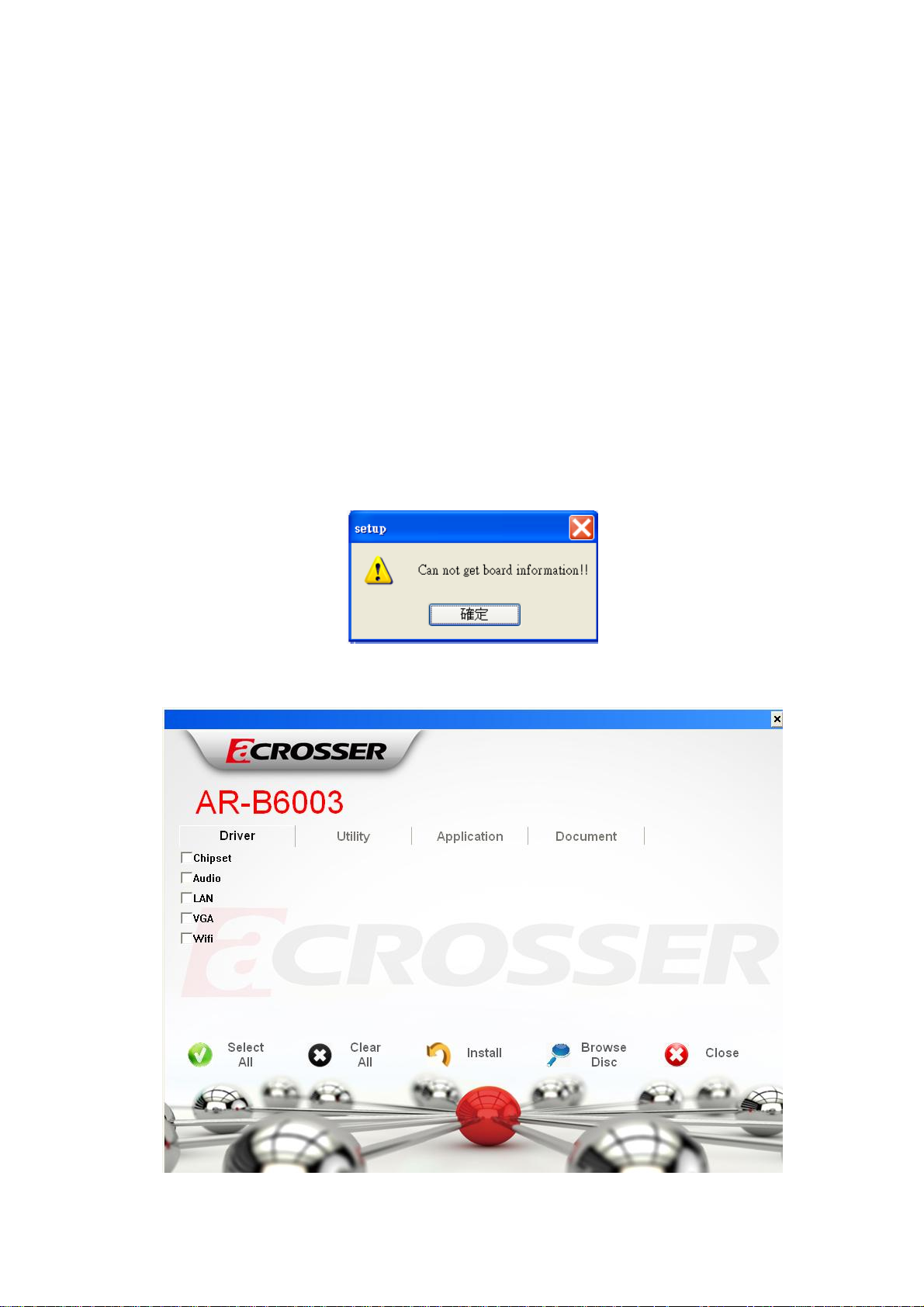
5.1 Driver CD Interface Introduction
Acrosser provides the driver CD including the drivers, utilities,
applications and documents. Once putting into optical driver, it will run
automatically. The driver CD will also detect the MB information to see if they
are matched. The following error message appears if you get an incorrect
driver CD.
5.1.1 Driver Page
38
Page 39

Click the item, all the drivers will be selected.
Click the item, all selected items will be cancelled.
39
Page 40

Click the “Install” icon to install the selected drivers.
Click the item to browse the CD contents.
40
Page 41

Click the icon to close the program.
41
Page 42

5.1.2 Utility Page
There is one utility for AR-B6003. The detailed information please refers
to Software Programming Guide for how to use the API.
Double click the “GPIO_Watchdog Setting Tool” to run the utility.
42
Page 43

5.1.3 Application Page
There is one application for Acrobat reader installing.
Double click the “Acrobat Reader 9.2” to install the application.
43
Page 44

5.1.4 Document Page
This page will provide Acrosser board and system user manual. Please
remember to install the Acrobat Reader before you read the manual.
Double click the manual item to read the user manual.
44
Page 45

Please install the Acrobat Reader when you see the message.
45
Page 46

5.2 Windows XP 32bit Driver Installation
5.2.1 Please put the driver disk to optical driver. The
program will appear on the screen. Please click the “Select
All” icon.
46
Page 47

5.2.2 Click the “Install” icon to install the drivers.
5.2.3 Finish the driver installation. Please click “Yes” to
restart the system.
47
Page 48

5.3 Windows 7 32/64bit Driver Installation
5.3.1 Please put the driver disk to optical driver. Then click
the “Run setup.exe” to run the install program.
48
Page 49

5.3.2 The program will appear on the screen. Please click the
“Select All” icon.
5.3.3 Click the “Install” icon to install the drivers.
49
Page 50

5.3.4 Finish the driver installation. Please click “Yes” to
restart the system.
50
Page 51

Chapter 6 Software Installation
and Programming Guide
6.1 Introduction
Overview of GPIO and Watchdog
AR-B6003 provides both a GPIO interface and a Watchdog timer. Users can use
the GPIO and Watchdog APIs to configure and to access the GPIO interface and the
Watchdog timer. The GPIO has four input pins and four output pins. The Watchdog
timer can be set to 1~255 seconds. Setting the timer to zero disables the timer. The
remaining seconds of the timer to reboot can be read from the timer.
In this GPIO and Watchdog package, on Linux and Windows platform, we
provide:
1. API source code.
2. GPIO and Watchdog test utility and the utility source code.
51
Page 52

6.2 File Descriptions
GPIO and Watchdog
On Linux platform:
1. sio_acce.c
The source code of the Watchdog and GPIO APIs for accessing the SuperIO.
2. sio_acce.h
This file includes the declarations of the APIs and macro definitions.
3. main.c
The source code of the utility.
4. Makefile
On Windows platform:
1. AR-B6003.h
The header file of the APIs and macro definition. This header file is an aggregate
header which includes APIs declarations and macros for GPIO, Watchdog.
2. AR-B6003.lib
The API library in static library format. This library is an aggregate library. It
includes APIs for GPIO, Watchdog.
3. AR-B6003.dll
The API library in dynamically linked library format. This library is an aggregate
library. It includes APIs for GPIO, Watchdog.
4. errno.h
The macro definitions of returned error code.
5. GPIO_Watchdog.cpp
The source code of the utility.
52
Page 53

6.3 API List and Descriptions
GPIO
1. Syntax:
i32 getInChLevel( i32 channel, u8 *val )
Description: Get the value of GPIO Input and put the value at *val.
Parameters:
I. The parameter ‘channel’ indicates the GPIO Input pins to show. Users can
use the macros GPI0, GPI1, GPI2, GPI3 to indicate the GPIO Input channel.
For example:
getInChLevel( GPI2, &val); // Indicate the GPIO Input channel 2
getInChLevel( GPI0 | GPI3, &val); // Indicate the GPIO Input
// channel 0 and channel 3
II. The parameter ‘val’ is an unsigned character pointer. The function puts the
values of the indicated GPIO channels at the memory pointed by ‘val’. The
bit 0 of *val shows the value of GPIO Input channel 0. The bit 1 of *val
shows the value of GPIO Input channel 1. Other bits show the
corresponding GPIO Input channels. Because there are only four channels,
bit 4 ~ bit 7 of *val are always zero.
Here is an example:
If GPIO Input channel 1 and channel 3 are both 1.
unsigned char ch;
getInChLevel( GPI1|GPI3, &ch );
The returned value of variable ‘ch’ is 0xa.
Return Value: If the function gets the values successfully, it returns 0. If any error,
it returns –1.
2. Syntax:
i32 setOutChLevel( i32 channel, u8 val )
Description: Set the value of GPIO Output according to the variable ‘val’.
53
Page 54

Parameters:
I. The parameter ‘channel’ indicates the GPIO Output pins to set. Users can
use the macros GPO0, GPO1, GPO2, GPO3 to indicate the GPIO Output
channels.
II. The parameter ‘val’ indicate the value to be set to GPIO Output channel.
The acceptable values are limited to 0 and 1.
For example:
/* Setting the GPIO Output channel 2 to 1 */
setOutChLevel( GPO2, 1 );
/* Setting the GPIO Output channel 0 and channel 3 to 0 */
getInChLevel( GPO0 | GPO3, 0 );
Return Value: If the function sets the values successfully, it returns 0. If any error,
it returns –1.
3. Syntax:
i32 getOutchLevel( i32 channel, u8 *val )
Description: Get the value of GPIO Output and put the value at *val.
Parameters:
I. The parameter ‘channel’ indicates the GPIO Output pins to show. Users can
use the macros GPO0, GPO1, GPO2, GPO3 to indicate the GPIO Output
channel. For example:
getOutChLevel( GPO2, &val); // Indicate the GPIO Output channel 2
/* Indicate the GPIO Output channel 0 and channel 3. */
getOutChLevel( GPO0 | GPO3, &val);
II. The parameter ‘val’ is an unsigned character pointer. The function puts the
values of the indicated GPIO channels at the memory pointed by ‘val’. The
bit 0 of *val shows the value of GPIO Output channel 0. The bit 1 of *val
shows the value of GPIO Output channel 1. Other bits show the
corresponding GPIO Output channels. Because there are only four channels,
bit 4 ~ bit 7 of *val are always zero.
54
Page 55

Here is an example:
If GPIO Output channel 0 and channel 2 are both 1.
unsigned char ch;
getOutChLevel( GPO0|GPO2, &ch );
The returned value of variable ‘ch’ is 0x5.
Return Value: If the function gets the values successfully, it returns 0. If any error,
it returns –1.
Watchdog
1. Syntax:
u8 getWtdTimer(void)
Description: This function reads the value of the watchdog time counter and
returns it to the caller.
Parameters: None.
Return Value: This function returns the value of the time counter and returns it to
the caller as an unsigned integer.
2. Syntax:
void setWtdTimer( u8 val )
Description: This function sets the watchdog timer register to the value ‘val’ and
starts to count down. The value could be 0 ~ 255. The unit is second. Setting the
timer register to 0 disables the watchdog function and stops the countdown.
Parameters: The parameter ‘val’ is the value to set to watchdog timer register.
The range is 0 ~ 255.
Return Value: None.
55
Page 56

6.4 Enable TESTSIGNING on Windows 7 X64 system
In order that the APIs works correctly on the Windows 7 X64 system, users have
to enable the boot configuration test-signing option before invoking any APIs. Please
follow the steps listed below to turn on the test-signing flag:
1. Invoke the ‘Command Prompt’ as an administrator.
2. Execute:
bcdedit.exe /set TESTSIGNING ON
56
Page 57

3. Run the ‘bcdedit’ again without any option. A new item ‘testsigning’ is enabled.
4. Reboot the system.
57
 Loading...