

Page 1

AR-B1690 User’s Guide
AR-B1690
Socket370 LPX POS Board with
VGA(CRT/LCD), LAN, Audio, DiskOnChip /
Compact Flash and Mini PCI
User’ s Guide
Edition: 1.11
Book Number: AR-B1690-05.0525
1
Page 2

AR-B1690 User’s Guide
Table of Contents
0. PREFACE………………………………………………………………………………………………………………………….4
0.1 COPYRIGHT NOTICE AND DISCLAIMER.....................................................................................................................................4
0.2 WELCOME TO THE AR-B1690 CPU BOARD................................................................................................................................4
0.3 BEFORE YOU USE THIS GUIDE...................................................................................................................................................4
0.4 RETURNING YOUR BOARD FOR SERVICE.................................................................................................................................4
0.5 TECHNICAL SUPPORT AND USER COMMENTS........................................................................................................................4
0.6 ORGANIZATION.............................................................................................................................................................................5
0.7 STATIC ELECTRICITY PRECAUTIONS ........................................................................................................................................5
1. INTRODUCTION..........................................................................................................................................................6
1.1 SPECIFICATIONS ..........................................................................................................................................................................7
1.2 PACKING LIST................................................................................................................................................................................7
2. SETTING UP SYSTEM................................................................................................................................................ 8
2.1 AR-B1690 OVERVIEW....................................................................................................................................................................8
2.2 SYSTEM SETTINGS.....................................................................................................................................................................10
2.2.1 Keyboard & Mouse Connector (PS1).....................................................................................................................................10
2.2.2 External Keyboard & Mouse Connector (KM1) ......................................................................................................................10
2.2.3 Hard Disk (IDE) Connector (IDE1, IDE2) ...............................................................................................................................11
2.2.4 FDD Port Connector (FDD1)..................................................................................................................................................12
2.2.5 Parallel Port Connector (LPT1) ..............................................................................................................................................12
2.2.6 CRT Connector (VGA1)..........................................................................................................................................................13
2.2.7 USB Connector (USB1 & USB2)............................................................................................................................................13
2.2.8 LCD Connector (LCD1)..........................................................................................................................................................14
2.2.9 LVDS Header (LVDS1)...........................................................................................................................................................14
2.2.10 Serial Port (COM1, COM2, COM3 and COM4)....................................................................................................................15
2.2.11 RS-485 Terminator Select (J7).............................................................................................................................................15
2.2.12 RS-485 Header (J5) .............................................................................................................................................................16
2.2.13 Touch Screen Connector (J18, J19).....................................................................................................................................16
2.2.14 PCI Slot (PC1)......................................................................................................................................................................16
2.2.15 Mini PCI Slot (PCI 2) ............................................................................................................................................................16
2.2.16 PCI Select (J17) ...................................................................................................................................................................16
2.2.17 CPU Setting System Bus Clock (SW1) ................................................................................................................................17
2.2.18 Compact Flash Connector (CF1)..........................................................................................................................................17
2.2.19 CD IN Connector (CD1)........................................................................................................................................................17
2.2.20 CPU Fan Power Connector (FAN1, FAN2) ..........................................................................................................................17
2.2.21 26-Pin Audio Connector (AUDIO1).......................................................................................................................................18
2.2.22 Infrared Connector (IR1).......................................................................................................................................................18
2.2.23 Voltage Select (J6 & J8).......................................................................................................................................................18
2.2.24 COM3-COM4 Voltage Select (J20, J21) ..............................................................................................................................19
2.2.25 Battery Jumper (J10)............................................................................................................................................................19
2.2.26 LED (J1) ...............................................................................................................................................................................19
2.2.27 D.O.C Socket (U1)................................................................................................................................................................20
2.2.28 DOC Address Select (J11)...................................................................................................................................................20
2.2.29 GPIO Connector (J2)............................................................................................................................................................20
2.2.30 GPIO address (J23)..............................................................................................................................................................21
2.2.31 AT Power Connector (AT1)..................................................................................................................................................21
2.2.32 External LED and Switch Connector (Panel1)......................................................................................................................21
2.2.33 Ethernet RJ-45 Connector (LAN1) .......................................................................................................................................22
2.2.34 DRAM Configuration (DIMM1, DIMM2)................................................................................................................................22
2.2.35 ATX Power Connector (ATX1) .............................................................................................................................................22
2.2.36 SYSTEM POWER SELECT (J24) ........................................................................................................................................22
3. CRT/LCD FLAT PANEL DISPLAY............................................................................................................................23
3.1 CRT CONNECTOR (VGA1)..........................................................................................................................................................23
3.2 LCD FLAT PANEL DISPLAYS......................................................................................................................................................23
4. WATCHDOG TIMER ................................................................................................................................................. 24
4.1 WATCHDOG TIMER SETTING ....................................................................................................................................................24
4.2 WATCHDOG TIMER TRIGGER....................................................................................................................................................24
5. BIOS CONSOLE........................................................................................................................................................25
5.1 BIOS SETUP OVERVIEW.............................................................................................................................................................25
5.2 STANDARD CMOS SETUP..........................................................................................................................................................26
5.3 ADVANCED CMOS SETUP..........................................................................................................................................................27
5.4 ADVANCED CHIPSET SETUP.....................................................................................................................................................29
5.5 POWER MANAGEMENT..............................................................................................................................................................30
5.6 PCI/PLUG AND PLAY...................................................................................................................................................................31
5.7 PERIPHERAL SETUP...................................................................................................................................................................32
5.8 AUTO-DETECT HARD DISKS......................................................................................................................................................33
5.9 PASSWORD SETTING.................................................................................................................................................................33
5.10 LOAD DEFAULT SETTING.........................................................................................................................................................33
5.10.1 Auto Configuration with Optimal Setting...............................................................................................................................33
5.10.2 Auto Configuration with Fail Safe Setting.............................................................................................................................33
5.11 BIOS EXIT...................................................................................................................................................................................33
5.12 BIOS UPDATE ............................................................................................................................................................................34
2
Page 3

AR-B1690 User’s Guide
APPENDIX A. I/O & MEMORY MAP.............................................................................................................................35
APPENDIX B. INTERRUPT REQUEST (IRQ)............................................................................................................... 36
3
Page 4

AR-B1690 User’s Guide
0. PREFACE
0.1 COPYRIGHT NOTICE AND DISCLAIMER
This document is copyrighted, 2002, by Acrosser Technology Co., Ltd. All rights are reserved. No part of this
manual may be reproduced, copied, transcribe d, stored in a retrieval system, or translated into any language or
computer language in any form or by any means, such as electronic, mechanical, magnetic, optical, chemical,
manual or other means without the prior written permission or original manufacturer.
Acrosser Technology assumes no responsibility or warranty with respect to the content in this manual and
specifically disclaims any implied warranty of merchantabilit y or fitness for any particular purpose. Furthermore,
Acrosser Technology reserves the right to make improvements to the products described in this ma nual at any
times without notice. Such revisions will be posted on the Internet (WWW.ACROSSER.COM)
Possession, use, or copy of the software described in this publication is authorized onl y pursuant to valid written
license from Acrosser or an authorized sub licensor.
ACKNOWLEDGEMENTS
Acrosser, AMI, IBM PC/AT, VIA, Windows 3.1, MS-DOS…are registered trademarks.
All other trademarks and registered trademarks are the property of their respective owners.
0.2 WELCOME TO THE AR-B1690 CPU BOARD
This guide introduces the Acrosser AR-B1690 CPU Board.
Use information provided in this manual describes this card’s functions and features. It also helps you start, set up
and operate your AR-B1690. General system information can also be found in this publication.
0.3 BEFORE YOU USE THIS GUIDE
Please refer to the Chapter 2, “System Setting,” in this guide, if you have not already installed this AR-B1690.
Check the packing list before you install and make sure the accessories are completely included.
AR-B1690 CD provides the newest information regarding the CPU card. Please refer to the files of the
enclosed utility CD. It contains the modification and hardware & software information, and adding the
description or modification of product function after manual printed.
0.4 RETURNING YOUR BOARD FOR SERVICE
If your board requires any services, contact the distributor or sales representative from whom you purchase d the
product for service information. If you need to ship your board to us for service, be sure it is packed in a protective
carton. We recommend that you keep the original shipping container for this purpose.
You can help assure efficient servicing for your product by following these guidelines:
1. Include your name, address, daytime telephone, facsimile number and E-mail.
2. A description of the system configuration and/or software at the time of malfunction.
3. A brief description of the problem occurred.
0.5 TECHNICAL SUPPORT AND USER COMMENTS
Users comments are always welcome as they assist us in improving the quality of our products and the readability
of our publications. They create a very important part of the input used for product enhancement and revision.
We may use and distribute any of the information you provide in any way appropriate without incurring any
obligation. You may, of course, continue to use the information you provide.
If you have any suggestions for improving particular sections or if you find any errors on it, please send your
comments to Acrosser Technology Co., Ltd. or your local sales representative and indicate the manual title and
book number.
Internet electronic mail to: Sales@acrosser.com
acrosser@tp.globalnet.com.tw
as soon as possible.
4
Page 5

AR-B1690 User’s Guide
0.6 ORGANIZATION
This information for users covers the following topics (see the Table of Contents for a detailed listing):
Chapter 1, “Introduction”, provides specifications and packing list.
Chapter 2, “Setting Up System”, describes how to adjust the jumpers and the connector settings.
Chapter 3,“CRT/LCD Flat Panel Display”, describes the configuration and installation procedure for using LCD and
CRT displays.
Chapter 4, “Watchdog Timer”, describes watchdog timer setting and trigger.
Chapter 5, “BIOS Console”, provides the BIOS settings options.
Appendix A, Memory & I/O Map
Appendix B, Interrupt Request (IRQ)
0.7 STATIC ELECTRICITY PRECAUTIONS
Before removing the board from its anti-static bag, read this section about static electricity precautions.
Static electricity is a constant danger to computer systems. The charge that can build up in your body may be more
than sufficient to damage integrated circuits on any PC board. It is, therefore, important to observe basic
precautions whenever you use or handle computer comp onents. Although areas with humid climates are much
less prone to static build-up, it is always best to safeguar d against acci dents that may result in expensive repairs.
The following measures should be sufficient to protect your equipment from static discharge:
Touch a grounded metal object to discharge the static electricity in your body (or ideally, wear a grounded
wrist strap).
When unpacking and handling the board or other system components, place all materials on an anti-static
surface.
Be careful not to touch the components on the board, especially the “golden finger” connectors on the
bottom of the board.
5
Page 6
AR-B1690 User’s Guide
1. INTRODUCTION
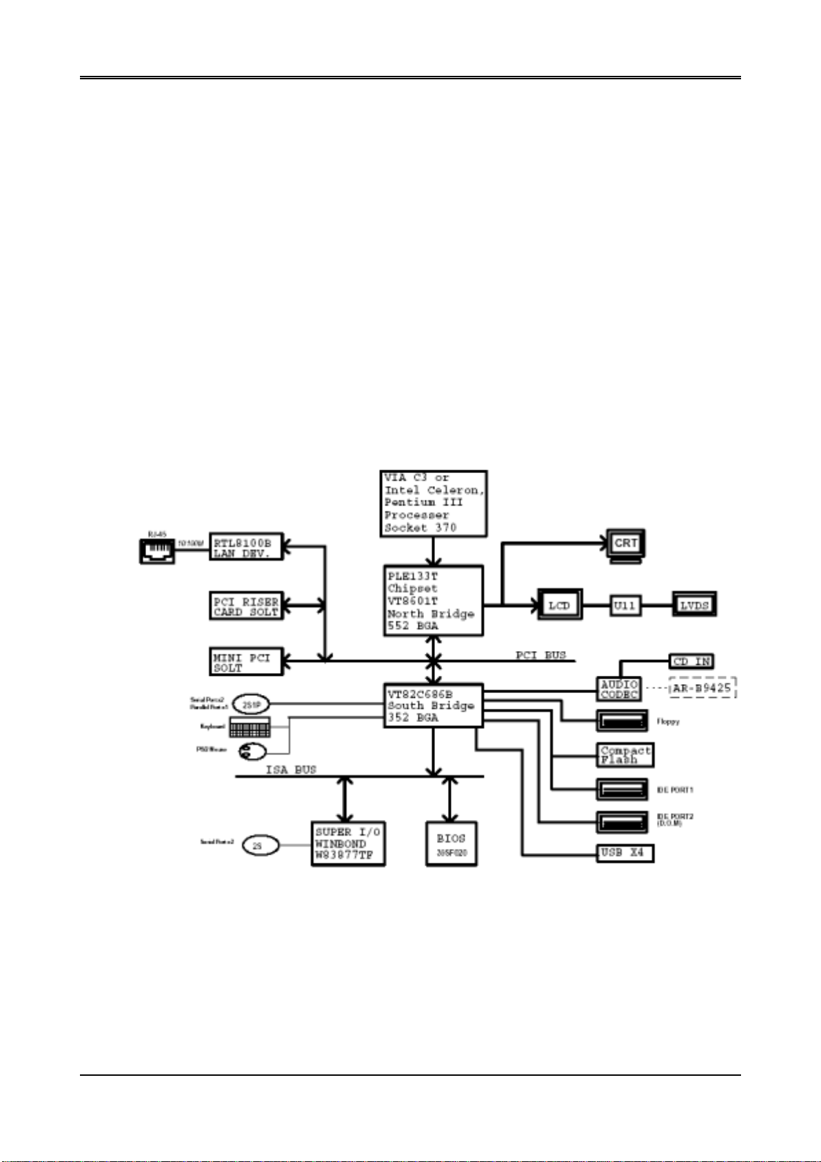
Welcome to the AR-B1690 POS Single Board Computer. The AR-B1690 board is POS form factor board, which
comes equipped with economical performance with the Celeron series processors, or the impressive performance
of the Pentium III series Processors, or Low power VIA C3 series Processors with the VIA ® advanced chipset
Apollo PLE133T (VT8601T and VT82C686B). This product is designed for the system manufacturers, integrators,
or VARs that want to provide all the performance, reliability, and quality at a reasonable price.
In addition, the AR-B1690 provides on chip VGA. The VGA, which provides up to Ture Color (32 bit) 1024x768, or
High Color (16 bit) 1280x1024 resolution. The VGA memory is share main memory (2M, 4M, or 8M). AR-B1690
also has 18-bit TFT LCD and LVDS function in the system.
The AR-B1690 is loaded with special on-board features that rival full-size systems. It has one network controller on
board, uses RealTek RTL8100B LAN controller, a fully integrated 10/100BASE-TX solution with high performance
networking functions. DOC and CompactFlash™. There is a Mini PCI socket for optional international version
modem, plus optional support for AC97 3D stereo surround sound with CD-input, AR-B9425 (line-in, line-out and
speaker-out, microphone). The AR-B1690 also includes two 168-pin DIMM sockets for up to 1G MB total on-board
memory. The ar-b1690 has four on-board serial ports; COM3 and COM4 have +5/+12 V power or GND, two USB
connectors for 4 USB ports, watchdog timer and tough industrial grade construction. All these features make the
AR-B1690 a very "system integrator friendly" solution, perfect for handling POS applications in the harshest
unmanned environments.
AR-B1690 System Block Diagram
6
Page 7

AR-B1690 User’s Guide
1.1 SPECIFICATIONS
CPU: Intel Pentium III / Celeron, VIA C3 Socket 370 CPU
DMA channels: 7
Interrupt levels: 15
Chipset: VIA ® Apollo PLE133T ( VT8601T Integrated 2D / 3D graphics accelerator and VT82C686B)
RAM memory: Supports SDRAM PC133, on-board Two 168-pin DIMMs up to 1.0GB SDRAM memory
module.
VG A Controller: Embedded VGA controller, Screen Resolution: up to Ture Color(32 bit)1024x768, or High
Color(16 bit) 1280x1024.
Display Interface: CRT – D-SUB 15-pin female connector
LVDS – for 18 bit TFT LCD Panel, 2x13x2.00mm pin-header connector
LCD – for 18 bit TFT LCD Panel, 2x22x2.00mm pin-header connector
Ultra AT A/33/66/100 IDE Interface: Two PCI Enhance IDE channel. The south bridge VT82C686B supports
Ultra ATA/33/66/100 IDE interface. To support Ultra ATA66/100 Hard disk, a specified cable must be
available.
Floppy disk drive interface: 2.88 MB, 1.44MB, 1.2MB, 720KB, or 360KB floppy disk drive.
SSD: Supp ort one socket for DiskOnChip.
C. F.: Supports Compact Flash Type I interface
Series po rts: On-board D-SUB 9-pin male external port for COM1 with RS-232C/Touch Screen
Touch Screen uses 2.0mm 3-pin JST connector
On-board D-SUB 9-pin male external port for COM2 with RS-232C/Touch Screen
Touch Screen uses 2.0mm 3-pin JST connector
On-board one 2x5x2.54mm pin-header connector for COM3 with RS-232C/RS-485
On-board one 2x5x2.54mm pin-header connector for COM4 with RS-232C
COM3 and COM4 Serial ports provides +5V & +12V power supply
Parallel Port: On-board one D-SUB 25-pin female external port for Parallel port LPT1, supports
SPP/EPP/ECP modes.
Expansion Slot: On-board one PCI slot, supports PCI Riser card for two PCI expansion slots.
Mini PCI: On board one Mini PCI socket.
IrDA port: Supports IrDA (HPSIR) and ASK (Amplitude Shift Keyed) IR port multiplexed on COM2.
USB port: one external port for 2 USB ports & one 2x5x2.54mm pin-header connector for 2 USB ports
Audio: onboard AC’97 Codec, Supports two channel Left/Right Line IN/OUT, and Left/Right speaker out,
MIC IN, CD IN.
Watchdog timer: Software programmable 1~63sec.
Ethernet: 1 RTL8100B chipset, supports 10/100M baseT with 1 RJ-45 connector built-in LED.
K/B & Mouse: On-board PS/2 Keyboard and Mouse 6-pin Mini-DIN external connector
On-board 1x6x2.00mm JST connector for Keyboard and PS/2 Mouse
GP I/O: On-board 2x4x2.00mm pin-header connector for 4-bit input and 4- bit output, TTL level.
Power Connector: ATX & AT (P8/P9) power input connector
Power Req.: +5V 6A and +12V 1A maximum
PC Board: 6 layers, EMI considered
Dimensions: 220 mm x 235 mm ( 8.66 ” x 9 .25 ”)
Operatin g Temperature: 0° ~ 60℃
1.2 PACKING LIST
These accessories are included with the system. Before you begin installing your AR-B1690 board, please make
sure that the following items have been included inside the AR-B1690 package.
z The quick setup manual
z 1 AR-B1690 CPU board
z 1 Hard disk drive adapter cable for 3.5” hard disk
z 1 Hard disk drive adapter cable for 2.5” hard disk
z 1 Floppy disk drive adapter cable
z 1 Software utility CD
z 2 RS-232 and 1 PS/2 Mouse & Keyboard interface cable mounted on brac ket
7
Page 8
AR-B1690 User’s Guide
2. SETTING UP SYSTEM
This chapter describes how to install the AR-B1690. At first, the layout of AR-B1690 is sho wn, and the unpacking
information that you should be careful is described.
Overview
System Settings
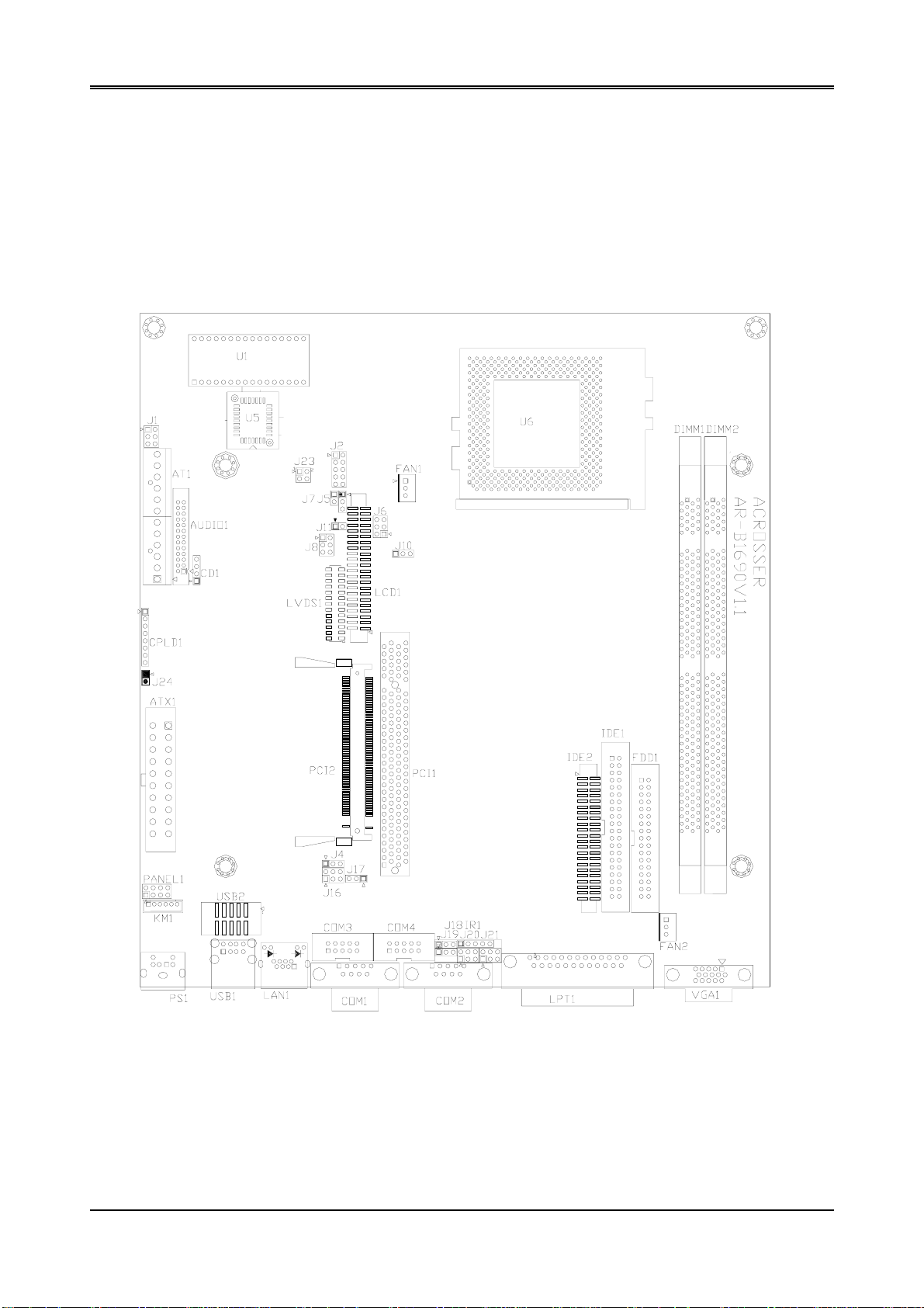
2.1 AR-B1690 OVERVIEW
TOP PLACEMENT
8
Page 9
AR-B1690 User’s Guide
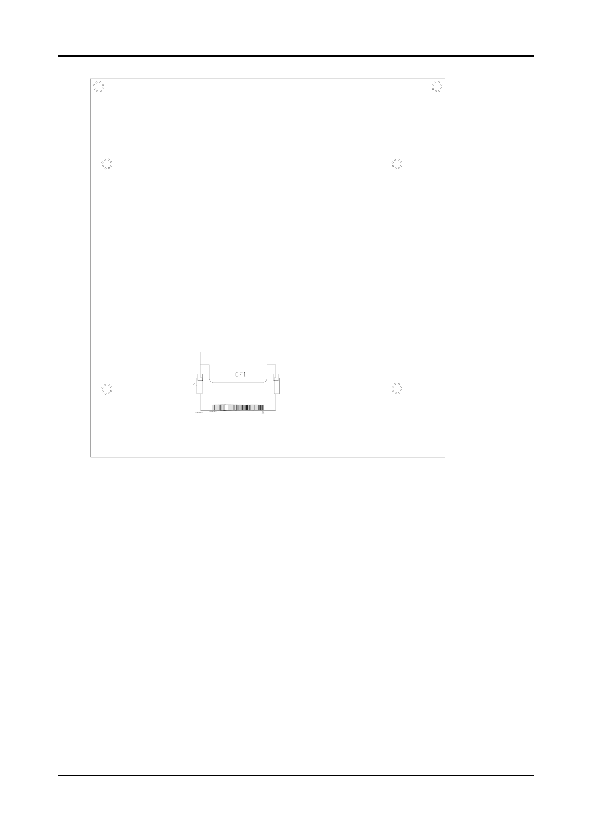
BOTTOM PLACEMENT
9
Page 10

AR-B1690 User’s Guide
2.2 SYSTEM SETTINGS
Jumper pins allow you to set specific system parameters. Set them by changing the pin loc ation of the jumper
blocks. (A jumper block is a small plastic-encased conductor that slips over the pins.) To change a jumper
setting, remove the jumper from its current location with your fingers or small needl e-nosed pliers. Place the
jumper over the two pins designated for the desired setting. Press the jumper evenly onto the pins. Be careful
not to bend the pins.
We will show the locations of the AR-B1690 jumper pins, and the factory-default settings.
CAUTION: Do not touch any electronic components unless you are safely grounded. Wear a grounded wrist
strap or touch an exposed metal part of the system unit chassis. The static discharges from your fingers can
permanently damage electronic components.
2.2.1 Keyboard & Mouse Connector (PS1)
The PS1 is a 6-pin Mini DIN keyboard & Mouse connector. This keyboard & Mouse connector is PS/2 type
connector. This connector is also for a standard IBM-compatible keyboard when used with the included PS/2
keyboard & Mouse adapter cable.
1 MOUSE DATA
2 KB DATA
3 GND
4 VCC
5 MOUSE CLOCK
6 KB CLOCK
PS1
1
2
3
5
4
6
Front View
2.2.2 External Keyboard & Mouse Connector (KM1)
KM1 provides connection of PS2 mouse and Keyboard. Those pins for keyboard & mouse are parallel with KM1,
which provides another selection of connecting with keyboard & mouse.
KM1
1 6
1.MOUSE DATA
2.KB DATA
3.GND
4.VCC
5.MOUSE CLOCK
6.KB CLOCK
10
Page 11
AR-B1690 User’s Guide
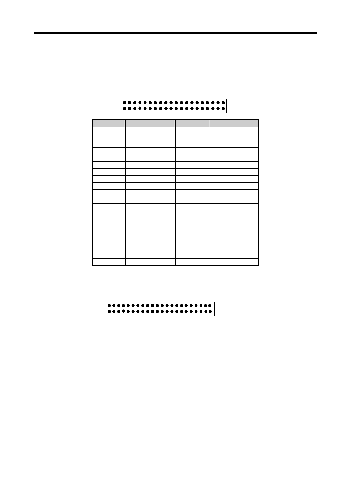
2.2.3 Hard Disk (IDE) Connector (IDE1, IDE2)
(1) 40 Pin Hard Disk Connector (IDE1)
A 40-pin header type connector (IDE1) is provided to interface with up to two embedded hard disk drives (IDE
PCI bus). This interface, thr ough a 40-pin cable, allows the user to connect up to two drives in a “daisy
chain” fashion. To enable or disable the hard disk controller, please use the BIOS Setup program. The
following table illustrates the pin assignments of the hard disk drive’s 40-pin connector.
2 40
1 39
Pin Signal Pin Signal
1 -RESET 2 GROUND
3 DATA 7 4 DATA 8
5 DATA 6 6 DATA 9
7 DATA 5 8 DATA 10
9 DATA 4 10 DATA 11
11 DATA 3 12 DATA 12
13 DATA 2 14 DATA 13
15 DATA 1 16 DATA 14
17 DATA 0 18 DATA 15
19 GROUND 20 NOT USED
21 DRQ A 22 GROUND
23 -IOW A 24 GROUND
25 -IOR A 26 GROUND
27 -CHRDY A 28 NOT USED
29 DACK A 30 GROUND
31 -IRQ A 32 NOT USED
33 SA 1 34 NOT USED
35 SA 0 36 SA 2
37 CS 0 38 CS 1
39 HD LED A 40 GROUND
(2) 44 Pin Hard Disk Connector (IDE2)
The on-board 44-pin mini-pitched IDE interface is used to let user support either a 2.5" HDD.
2 44
1 43
11
Page 12

AR-B1690 User’s Guide
2.2.4 FDD Port Connector (FDD1)
The AR-B1690 provides a 34-pin header type connector for supporting up to two floppy disk drives. To enable or
disable the floppy disk controller, please use the BIOS Setup program.
2 34
1 33
Pin Signal Pin Signal
1-33(odd) GROUND 18 -DIRECTION
2 DRVEN 0 20 -STEP OUTPUT PULSE
4 NOT USED 22 -WRITE DATA
6 DRVEN 1 24 -WRITE ENABLE
8 -INDEX 26 -TRACK 0
10 -MOTOR ENABLE 0 28 -WRITE PROTECT
12 -DRIVE SELECT 1 30 -READ DATA
14 -DRIVE SELECT 0 32 -SIDE 1 SELECT
16 -MOTOR ENABLE 1 34 DISK CHANGE
2.2.5 Parallel Port Connector (LPT1)
The connector for the parallel port is a 25-pin D-type female connector.
D-type Connector
DB-25 Signal DB-25 Signal
14 25
1
1 -Strobe 14 -Au t o F o r m F e ed
2 Data 0 15 -Error
3 Data 1 16 -Initialize
4 Data 2 17 -Printer Select In
5 Data 3 18 Ground
6 Data 4 19 Ground
7 Data 5 20 Ground
8 Data 6 21 Ground
9 Data 7 22 Ground
10 -Acknowledge 23 Ground
11 Busy 24 Ground
12 Paper 25 Ground
13 Printer Select -- No Used
13
12
Page 13

AR-B1690 User’s Guide
2.2.6 CRT Connector (VGA1)
VGA1 is a standard 15-pin D-SUB connector commonly used for VGA.
VGA1
6
1
2
3
4
5
10
1 Red
2 Green
3 Blue
11
12
4,11 N.C
13
5&10 Ground
14
6,7&8 AGND
15
9 VCC
12 SDA
13 Horizontal Sync
14 vertical Sync
15 SCL
2.2.7 USB Connector (USB1 & USB2)
The Universal Serial Bus (USB) controller is USB V1.1 and Universal H CI V1.1 compliant. The Universal Serial
Bus (USB) standard is a low-to-medium speed interface for the connection of PC peripherals, which gives
complete Plug & Play, and hot attach/detach for up to 127 external devices.
USB is a leading edge technology that allows the user to quickly and easily add a wide range of peripheral devices
from printers to keyboards and telephony devices to fax/modems. Universal Host Controller Interface (UHCI) and
future support for the Open Host Controller Interface (OHCI) ensure USB compatibility and usability well into the
future.
The CPU board supports four Universal Serial Bus ports. An optional external port bracket attaches to the onboard
connector via an attached cable. With the optional port bracket installed you can attach USB devices to the
external ports. If the USB ports are installed, the USB Controller line in the Integrated Peripherals section of the
CMOS Setup utility must be set to “Enabled”. USB ports may also require Operating System support for USB
devices.
USB1
5 6 7 8 1.VCC
2.DATA0+
3.DATA0-
1 2 3 4
4.GND
USB2
USB2 use an adapter cable to interface with external equipment.
2 10 1.VCC
5.VCC
6.DATA1+
7.DATA1-
8.GND
5.DATA3+
2.VCC
3.DATA3-
6.DATA4+
7.8.GND
1 9
4.DATA4-
9.10.GND
13
Page 14

AR-B1690 User’s Guide
2.2.8 LCD Connector (LCD1)
2 44
1 43
LCD Pin Assignment
Pin Signal Pin Signal
1 GND 2 CLK
3 GND 4 HSYNCR
5 VSYNCR 6 GND
7 Not Used 8 Not Used
9 FPD0(R5) 10 FPD1(R4)
11 FPD2(R3) 12 FPD3(R2)
13 GND 14 FPD4(G5)
15 FPD5(G4) 16 Not Used
17 Not Used 18 FPD6(G3)
19 FPD7(G2) 20 GND
21 FPD8(B5) 22 FPD9(B4)
23 FPD10(B3) 24 FPD11(B2)
25 Not Used 26 Not Used
27 GND 28 FPD12(R1)
29 FPD13(R0) 30 FPD14(G1)
31 FPD15(G0) 32 FPD16(B1)
33 FPD17(B0) 34 GND
35 VCC 36 VCC
37 +12V 38 +12V
39 GND 40 GND
41 DISPENR 42 GKLENR
43 GND 44 VDDEN
2.2.9 LVDS Header (LVDS1)
14 26
1 13
PIN (LVDS1) FUNCTION PIN (LVDS1) FUNCTION
1 TXOUT0- 14 GND
2 TXOUT0+ 15 GND
3 TXOUT1- 16 VTX5
4 TXOUT1+ 17 VTX5
5 TXOUT2- 18 NC
6 TXOUT2+ 19 GND
7 TXCLK- 20 GND
8 TXCLK+ 21 VTX12
9 TXOUT3- 22 VTX12
10 TXOUT3+ 23 GND
11 VTKBP 24 NC
12 VTX5 25 NC
13 VTX5 26 NC
14
Page 15

2.2.10 Serial Port (COM1, COM2, COM3 and COM4)
y
AR-B1690 is equipped with four serial ports. COM1. COM2 is a standard RS-232 interface.
COM3.COM4 use an ada pter cable to interface with external equipment.
COM3 can be configured as a RS-485 or RS-232 port.
When we are configuring J16 or J4, COM3 can also be configured as an RS-232 or RS-485.
A. COM1. COM2
Only RS232
COM1
1
2
3
4
5
6
7
8
9
B. COM3
USED RS232 & RS485
9
10
J16
9
6
3
Factor
1
2
RS-232
Preset
1.DCD
2.DSR
3.RX
4.RTS
J4
7
4
1
5.TX
6.CTS
7.DTR
8.RI
9.GND
J16
9
6
3
RS-485
J4
7
4
1
C. COM 4
Only RS232
9
10
1
2
1.DCD
2.DSR
3.RX
4.RTS
5.TX
6.CTS
7.DTR
8.RI
9.GND
AR-B1690 User’s Guide
2.2.11 RS-485 Terminator Select (J7)
When there is only one line, the setting should be left off. If multiple blocks are used on a single line, it should be
set to “ ON” in order to properly terminate the connection for better transmission of data.
1
2
OFF
1
2
ON
Factory Preset
15
Page 16

AR-B1690 User’s Guide
2.2.12 RS-485 Header (J5)
1 2 3
1 N485+
2 N4853 GND
2.2.13 Touch Screen Connector (J18, J19)
J18 (or J19) is a serial port, which is parallel with COM1 (or COM2). It provides another choice when user needs a
serial port but need to connect from board directly without connecting through a D-t ype connector. The typical
application is a touch screen panel.
1 2 3
1 RXDF
2 TXDF
3 GND
2.2.14 PCI Slot (PC1)
On-board one PCI slot (PCI1), supports PCI Riser card for two PCI expansion slots.
2.2.15 Mini PCI Slot (PCI 2)
On-board one Mini PCI slot (PCI2)
2.2.16 PCI Select (J17)
1
2
3
Factory Preset
1-2 When riser card is applied,
Please set 1-2 close
2-3 Support one PCI card (Factory Preset)
16
Page 17

2.2.17 CPU Setting System Bus Clock (SW1)
The table below shows the correct setting to match the CPU frequency.
1 2 3 4
AR-B1690 User’s Guide
OFF
1 2 3 4 CPU PCI
OFF OFF OFF OFF 133 33.3
ON OFF OFF OFF 124 31
OFF ON OFF OFF 150 37.5
ON ON OFF OFF 140 35
OFF OFF ON OFF 105 35
ON OFF ON OFF 110 36.6
OFF ON ON OFF 115 38.3
ON ON ON OFF 120 40
OFF OFF OFF ON 100 33.3
ON OFF OFF ON 133 44.3
OFF ON OFF ON 112 37.3
ON ON OFF ON 103 34.3
OFF OFF ON ON 66 33 (Factory Preset)
ON OFF ON ON 83 41.6
OFF ON ON ON 75 37.5
ON ON ON ON 124 41.3
2.2.18 Compact Flash Connector (CF1)
50 1
Caution:
or CD/DVD-writer, at the same time because CF Card and Secondary connector (IDE2) use the same as I/O
address on the motherboard, it will cause hardware conflict or it will cause hardware crash.
Please avoid using Compact Flash Card and Secondary Devices (IDE2), Such as CD/DVD-ROM, HDD
2.2.19 CD IN Connector (CD1)
1 2 3 4
1.CDINL
2.3.GND
4.CDINR
2.2.20 CPU Fan Power Connector (FAN1, FAN2)
FAN1 and FAN2 are 3-pin header for the CPU fan. The fan must be a 12V fan.
2 1
3
1. GND
2. +12V
3. Fan Speed
17
Page 18

AR-B1690 User’s Guide
2.2.21 26-Pin Audio Connector (AUDIO1)
1 25
2 26
PIN Signal PIN Signal
1 AUXAL 2 LINEL
3 AUXAR 4 LINER
5 VCC 6 Not Used
7 AUDIOL 8 MICPH
9 AUDIOR 10 PCSPKO
11 GND 12 GND
13 Not Used 14 Not Used
15 GND 16 GND
17 Not Used 18 Not Used
19 Not Used 20 Not Used
21 Not Used 22 Not Used
23 Not Used 24 Not Used
25 GND 26 GND
Note:
the connector does not contain the GAME (MIDI) port signal. When AR-B1690 audio card is used with
this CPU board, the GAME port function is not supported.
2.2.22 Infrared Connector (IR1)
The Infra-red Header pin assignment is as follows:
1 5
1.VCC
2.NC
3.IR DATA RECE IVER
4.GND
5.IR DATA TRANSFER
2.2.23 Voltage Select (J6 & J8)
LCD
J6
1
3
5
JUMPER VOLTAGE NOTE
1-3 ON
2-4 ON
3-5 ON
4-6 ON
2
4
6
VCC3 Factory Preset
VCC
18
Page 19

LVDS
AR-B1690 User’s Guide
J8
1
2
3
5
4
6
JUMPER VOLTAGE NOTE
1-3 ON
2-4 ON
3-5 ON
4-6 ON
The AR-B1690 supports 5V and 3.3V LCD or LVDS displays.
LCD: Use J6 to change between 5V and 3.3V (default) panel video signal level.
LVDS: Use J8 to change between 5V and 3.3V (default) panel video signal level.
VCC
VCC3 Factory Preset
2.2.24 COM3-COM4 Voltage Select (J20, J21)
1
3
5
2
1-2 +12V (Factory Preset)
4
3-4 +5V
6
5-6 GND
2.2.25 Battery Jumper (J10)
1
2
3
1-2: ON-BOARD BATTERY (FACTORY PRESET)
2-3: CLEAR CMOS
Factory Preset
2.2.26 LED (J1)
1
3
5
HDD LED (IDE1): External LED connector for primary IDE channel.
HDD LED (LED2): External LED connector for secondary IDE channel.
Power LED: External LED connector for Watchdog status indication.
1-2: HDD LED (IDE1)
2
3-4: HDD LED (IDE2)
4
5-6: Power LED
6
1-3-5: VCC
19
Page 20

AR-B1690 User’s Guide
2.2.27 D.O.C Socket (U1)
DOC: 32 pin Disk-on-chip Socket
2.2.28 DOC Address Select (J11)
The J11 jumper is used to choose DOC address.
J11
1
2
JUMPER ADDRESS NOTE
ON D000:0000 Factory Preset
OFF D200:0000
2.2.29 GPIO Connector (J2)
Users could test GPIO function under ‘Debug’ program as follow:
2
1
10
9
1.GPI 3
3.GPI 2
5.GPI 1
7.GPI 0
9.GND
2.GPO 3 (MSB)
4.GPO 2
6.GPO 1
8.GPO 0 (LSB)
10.VCC
Users could test GPIO function under ‘Debug’ program as follow:
C:>debug
z O 215 01H
Generally, the J2’s Pin8 will be High Level, others output pin are Low Level.
z I 215
FC
Generally, suppose that J2’s Pin1 and Pin3 are High Level then will show “FC”
20
Page 21

2.2.30 GPIO address (J23)
The J23 jumper is used to choose GPIO address.
AR-B1690 User’s Guide
2
4
JUMPER ADDRESS
1-2 3-4
ON ON 215 (Factory Preset)
ON OFF 216
OFF ON 77
OFF OFF 78
1
3
2.2.31 AT Power Connector (AT1)
The power connection is a 12-pin connector (PS/2 or AT power standard) requirin g ±5 V and ±12 V power. Keep
the ground wires (black color) toward the middle when connecting t he power wire from the power supply.
12 1
1. POWER GOOD 7. GND
2. VCC 8. GND
3. +12V 9. –5V
4. –12V 10. VCC
5. GND 11. VCC
6. GND 12. VCC
2.2.32 External LED and Switch Connector (Panel1)
7 1
8
POWER LED
External LED connector is for power status indication.
1.PW-LED
3.GND
2
HARD DISK LED
External LED connector is for Hard Disk (IDE1 & IDE2) channel.
5.VCC
7. HD-LED
POWER BUTTON
When you choose ATX Power, the POWER BUTTON is used to connect to an external power button switch in
order to push the button to turn on the system. Actually, you can also turn off the system and push the button
for more than 4 seconds to turn off the system.
2.PW-BN
4.GND
RESET BUTTON
The RESET BUTTON is used to connect to an external reset switch. Shorting these two pins will reset the
system.
6.RST-SW
8.GND
21
Page 22

AR-B1690 User’s Guide
2.2.33 Ethernet RJ-45 Connector (LAN1)
The system supports onboard network connectivity. To utilize this function, install the network driver from the
utility diskette, and connect the cable to the following RJ-45 header.
PIN (CN8) FUNCTION
1 TPTX+
2 TPTX 3 TPRX+
4 Not Used
5 Not Used
6 TPRX7 Not Used
8 Not Used
1
8
2.2.34 DRAM Configuration (DIMM1, DIMM2)
It can assemble 16/32/64/128/256/512MB 168 pin DIMM Module Memory. When you set up 168-pin DIMM Module
Memory, AR-B1690 will auto-detect DRAM, and adopt correct save in order to make memory work till the best
situation.
Caution: Set up 168-pin DIMM Module Memory, please insert into slot vertical, if the direction is wrong and it leads
to failure, please confirm the direction is right.
2.2.35 ATX Power Connector (ATX1)
20
10
11
1
1. 3.3V 11. 3.3V
2. 3.3V 12. –12V
3. GND 13. GND
4. 5V 14. PS-ON
5. GND 15. GND
6. 5V 16. GND
7. GND 17. GND
8. PW-OK 18. –5V
9. 5VSB 19. 5V
10. 12V 20. 5V
2.2.36 SYSTEM POWER SELECT (J24)
Assume user uses AT insert Jumper at J24 Pin for ATX power Jumper is not required.
J24
JUMPER POWER NOTE
ON AT
OFF ATX Factory Preset
22
Page 23

AR-B1690 User’s Guide
3. CRT/LCD FLAT PANEL DISPLAY
This chapter describes the configuration and installation pro cedur es f or LCD & CRT displays. The following topics
are covered:
CRT Connector
LCD Flat Panel Displays
※ DON’T SUPPORT EXTERNAL VGA CARD
3.1 CRT CONNECTOR (VGA1)
The AR-B1690 supports CRT color monitors. It uses an onboard VGA chipset and you can use the VGA RAM 2.4
or 8 MB. For different VGA display modes, your monitor must possess certain characteristics (the right drivers) to
display the mode you want.
To connect to a CRT monitor, an adapter cable has to be connected to the VGA connector. VGA is used to
connect with a VGA monitor when you are using the on-board VGA controller as a display adapter. Pin assignments
for the VGA connector are as follows:
VGA1
6
1
2
3
4
5
10
VGA1: CRT Connector
3.2 LCD FLAT PANEL DISPLAYS
Figure 4-2 shows the connection between AR-B1690 and LCD panel.
AR-B1690
12V & backlight
Control
The VGA BIOS of AR-B1690 support 800X600 resolution TFT display. Connecting AR-B1690 to other LCD needs
different LCD BIOS. Please visit our web site (www.acrosser.com
department (csd@acrosser.com.tw
CN11
LCD Panel Block Diagram
) for supports of LCD connecting.
1 Red
2 Green
3 Blue
11
12
4,11 N.C
13
5&10 Ground
14
6,7&8 AGND
15
9 VCC
12 SDA
13 Horizontal Sync
14 vertical Sync
15 SCL
AR-B9416
Inverter
LCD
Panel
Backlight
Power
) or contact with our technical support
23
Page 24

AR-B1690 User’s Guide
4. WATCHDOG TIMER
This section describes the use of Watchdog Timer, including disable, enable, and trigger. AR-B1690 is equipped
with a programmable time-out period watchdog timer that occupies I/O port 443H. Users can use simple program to
enable the watchdog timer. Once you enable the watchdog timer, the program should trigger it every time before i t
times out. Watchdog Timer will generate a response (system or IRQ) due to system fails to trigger or disable
watchdog timer before preset timer, times out.
Time Base
Counter and
Compartor
RESET
Enable(D7)
Time Factor
(D0-D5)
Write and
Trigger
Watchdog
Register
Watchdog Block Diagram
4.1 WATCHDOG TIMER SETTING
The watchdog timer is a circuit that maybe be used from your program software to detect crash or hang up.
The Watchdog timer is automatically disabled after reset. Once you enabled the watchdo g timer, your program
should trigger the watchdog timer every time before it times out. After you trigger the watchdog timer, the timer will
be set to zero and start to count again. If your program f ails to trigger the watchdog t imer before times out, it will
generate a reset pulse to reset the system or trigger the IRQ 9 signal in order to tell your system that the watchdog
time is out.
Please refer to the following table in order to properly program Watchdog function
D7 D6 D5 D4 D3 D2 D1 D0
1 Enable Reset
Time period
0 Disable IRQ 9
Users could test watchdog function under ‘Debug’ program as follows:
C:>debug
z O 443 C8H
Generally, watchdog function would reset system after 8 seconds
z O 443 0
Disable watchdog function
C:>debug
z O 443 88H
Generally, watchdog function would generate IRQ 9 after 8 seconds
z O 443 0H
Disable watchdog function
4.2 WATCHDOG TIMER TRIGGER
After you enable the watchdog t imer, your program must write the same factor as triggering to the watchdog timer
at least once during every time-out period. You can change the time-out period by writing another timer factor to the
watchdog register at any time, and you must t r igger the watchdog during every new time-out period in next trigger.
24
Page 25

AR-B1690 User’s Guide
5. BIOS CONSOLE
This chapter describes the AR-B1690 BIOS menu displays and explains how to perform common tasks needed to
get up and running, and presents detailed explanatio ns of the elements found in each of the BI OS menus. The
following topics are covered:
z BIOS Setup Overview
z Standard CMOS Setup
z Advanced CMOS Setup
z Advanced Chipset Setup
z Power Management
z PCI/Plug and Play
z Peripheral Setup
z Auto-Detect Hard Disks
z Password Setting
z Load Default Setting
z BIOS Exit
5.1 BIOS SETUP OVERVIEW
The BIOS is a program used to initialize and set up t he I/O system of the computer, which includes the ISA bus
and connected devices such as the video display, diskette drive, and the keyboard.
The BIOS provides a menu-based interface to the console subsystem. The consol e subsystem contains speci al
software, called firmware that interacts directly with the hardware components and facil itates interaction between
the system hardware and the operating system.
The BIOS default values ensure that the system will function at its normal capability. In the worst situation the user
may have corrupted the original settings set by the manufact urer.
After the computer is turned on, the BIOS will perform diagnostics on the system and display the size of the
memory that is being tested. Press the [Del] key to enter the BIOS Setup program, and then the main menu will
show on the screen.
The BIOS Setup main menu includes some options. Use the [Up/Down] arrow key to highlight the option that you
wish to modify, and then press the [Enter] key to select the option and configure the functions.
Setup Main Menu
CAUTION:
1. AR-B1690 BIOS the factory-default setting is used to the <Auto Configuration with Optimal Settings> Acrosser
recommends using the BIOS default setting, unless yo u are very familiar with the setting functi on, or you can
contact the technical support engineer.
2. If the BIOS settings are lost, the CMOS will detect the <Auto Configuration with Fail Sa fe Settings> to boot the
operation system, this option will reduce the performance of the system. Acrosser reco mmends choosing the
<Auto Configuration with Optimal Setting> in the main menu. This option gives best-case values that should
optimize system performance.
3. The BIOS settings are described in detail in this section.
25
Page 26

AR-B1690 User’s Guide
5.2 STANDARD CMOS SETUP
The <Standard CMOS Setup> option allows you to record some basic system hardware configuration and set the
system clock and error handling. If the CPU board is alread y installed in a working system, you will not need to
select this option anymore.
Standard CMOS Setup
Date & Time Setup
Highlight the <Date> field and then press the [Page Up] /[Page Down] or [+]/[-] keys to set the current date.
Follow the month, day and year format.
Highlight the <Time> field and then press the [Page Up] /[Page Down] or [+]/[-] keys to set the current date.
Follow the hour, minute and second format.
The user can bypass the date and time prom pts by creating an AUT OEXEC.BAT file. For information on how to
create this file, please refer to the MS-DOS manual.
Hard Disk Setup
The BIOS supports various types for user settings, The BI OS supports <Pri Master>, <Pri Slave>, <Sec Mast er>
and <Sec Slave> so the user can install up to two hard disks. For the master and slave jumpers, please refer to
the hard disk’s installation descriptions and the hard disk jumper settings in section three of this manual.
You can select <AUTO> under the <TYPE> and <MODE> fields. This will enable auto detection of your IDE
drives during boot-up. This will allow you to change your hard drives (with the power off) and t hen power on
without having to reconfigure your hard drive type. If you use older h ard disk drives, which do not support this
feature, then you must configure the hard disk drive in the standar d method as described above by the <USER>
option.
Floppy Setup
The <Standard CMOS Setup> option records the types of floppy disk drives installed in the system.
To enter the configuration value for a particular drive, highlight its corresponding field and then select the drive type
using the left-or right-arrow key.
Boot Sector Virus Protection
This option protects the boot sector and partition tabl e of your hard disk against accidental modifications. Any
attempt to write to them will cause the system to halt and display a warning message. If this occurs, you can
either allow the operation to continue or use a bootable virus-free floppy disk to reboot and investigate your system.
The default setting is <
Installation of new operating systems requires that you disable this to prevent write errors.
Disabled>. This setting is recommended because it conflicts with new operating s ystems.
26
Page 27

AR-B1690 User’s Guide
5.3 ADVANCED CMOS SETUP
The <Advanced CMOS Setup> option consists of configuration entries that allow you to improve your system
performance, or let you set up some system features according to your preference. Some entries here are
required by the CPU board’s design to remain in their default settings.
Advanced CMOS Setup
Quick Boot
This category speeds up Power On Self Test (POST) after you p ower on the computer. If it is set to Enabled,
BIOS will shorten or skip some check items during POST.
1st Boot Device
2nd Boot Device
3rd Boot Device
These options determine where the system looks first for an operating system.
S.M.A.R.T for Hard Disks
S.M.A.R.T is abbreviation of Self-Monitorin g Analysis and Reporting Technology. It is reliable and precautious
technology. When Hard Disk disorder, it prevents Hard Disk from the loss of data.
Boot Up Num-Lock
This item is used to activate the Num-Lock function upon system boot. If the setting is on, after a boot, the
Num-Lock light is lit, and user can use the number key.
Floppy Drive Swap
The option reverses the drive letter assignments of your floppy disk drives in the Swap A, B setting, otherwise
leave on the setting of
feature. It is functionally the same as physically interchanging the conn ectors of the floppy disk drives. When
Enabled>, the BIOS swapped floppy drive assignments so t hat Drive A becomes Drive B, and Drive B becomes
<
Drive A under DOS.
Disabled (No Swap). This works separat ely from the BIOS Features floppy disk swap
Floppy Drive Seek
If the <Floppy Drive Seek> item is setting Enabled, the BIOS will seek the floppy <A> drive one time upon boot up.
27
Page 28

AR-B1690 User’s Guide
PS/2 Mouse Support
The setting of Enabled allows the system to detect a PS/2 mouse on boot up. If detected, IRQ12 will be used for
the PS/2 mouse. IRQ 12 will be reserved for expansio n cards if a PS/2 mouse is not detected.
reserve IRQ12 for expansion cards and therefore the PS/2 mouse will not function.
Disabled will
Primary Display
The option is used to set the type of video display card installed in the system.
Password Check
This option enables password checking every time the computer is po wered on or every time the BIOS Setup is
executed. If
is chosen, the password prompt appears if the BIOS executed.
Always is chosen, a user password prompt appears every time the computer is turned on. If Setup
Boot to OS/2
When using the OS/2 operating system, yo u need to Yes this option other wise leave this on the setup default of
No.
L1 Cache
This option controls to Enabled or Disabled the CPU’s Level 1 built-in catch.
L2 Cache
This option controls to Enabled or Disabled the CPU’s Level 2 built-in catch.
System BIOS Cacheable
Enabled this option to enhance system performance by shado wing and caching system BIOS shadow functio ns
will be ignored.
Shadow Memory
Each of segments provides three options Disabled, Enabled, and Cached for fast er adapt er’s ROM executions.
However this shadow function is Chipset oriented and depe ndent on system hard ware feature. In gener al, C000
64K will be allocated for VGA BIOS and set to Cached to get higher display performance by shadowing and
caching feature. If user chooses Enabled setting, onl y BIOS shadow function is active.
28
Page 29

AR-B1690 User’s Guide
5.4 ADVANCED CHIPSET SETUP
This option controls the configuration of the board’s chipset. Control keys f or this screen are the same as for the
previous screen.
Advanced Chipset Setup
Configure SDRAM Timing by SPD
SPD is the abbreviation Serial Presence Detect. SPD takes accord the chip types, capacity, timing, voltage data.
The system can auto adjust memory according to the data to reach the best situation.
The Choice: Enabled, Disabled
DRAM Frequency
PC-100 means the memory bus is running at 100MHz. PC-133 means the memory bus is running at 133MHz.
The Choice: 66Mhz, 100Mhz, 133Mhz
SDRAM CAS Latency Time
When synchronous DRAM is installed, the number of clock c ycles of CAS latency depends on the DRAM timing.
The Choice: 2, 3
Memory Hole
You can reserve this area of system memory for ISA adapter ROM. When this area is reserved, it cannot be
cached. The user information of peripherals t hat need to use this area of s ystem memory usually discus ses their
memory requirements.
AGP Aperture Size
The item is to set up AGP display to use how much memory to save Texture Data.
USB Controller
This option can enable ALL USB Port, USB Port 0&1,USB Port 2&3, or Disabled USB function.
USB Device Legacy Support
These options are used to Enabled the USB funct ion and it ’ s onl y us eful i n t he DOS mode. T he USB f unction s et s
Enabled will occupy IRQ10.
29
Page 30

AR-B1690 User’s Guide
5.5 POWER MANAGEMENT
This section is used to configure power management featur es. This <Power management Setup> opt ion allows
you to reduce power consumption. This feature turns off the vide o display and shuts down the hard disk after a
period of inactivity.
Power Management
ACPI Aware O/S
The option YES is for ATX power, the option NO is for AT Power.
System Thermal
If the choice <monitor>is chose, the system will alarm when the system temperature is beyond the critical
temperature.
Thermal Active Temperature
Thermal Slow Clock Ratio
This item is to set up the Operating Frequency of system clock in po wer saving mode, to set a suitable clock
frequency ratio, which between standard CPU clock and CPU clock in power saving mode when the temperature is
beyond the critical temperature.
30
Page 31

AR-B1690 User’s Guide
5.6 PCI/PLUG AND PLAY
This section is used to configure PCI / Plug and Play features. The <PCI & PNP Setup> option configures the PCI
bus slots. All PCI bus slots on the system use INTA#, thus all installed PCI cards must be set to this value.
PCI / Plug And Play
Plug and Play Aware O/S
Set this option to Yes if the operating system installed in the computer is Plug and Pl ay-aware. The BI OS only
detects and enables PnP ISA adapter cards that are required for system boot. The Windows 95 operating system
detects and enables all other PnP-aware adapter cards. Windows 95 is PnP-a ware. Set this option <
operating system (such as DOS, OS/2, Windows 3.x) does not use PnP. You must set this option correctly or
PnP-aware adapter cards installed in your computer will not be configured properly.
Clear NVRAM
This sets the operating mode of the boot block area of t he BIOS FLASH ROM to allow programming in the Yes
setting.
PCI Latency Timer (PCI Clocks)
This option sets latency of all PCI devices on the PCI bus. The settings are in units equal to PCI clocks.
Primary Graphic Adapter
This option is set to use PCI bus or AGP. The AGP mode will get system a faster processing speed.
DMA & IRQ
These options specify the bus that the nam ed IRQs/DMAs lines are used on. T hese options allow you to spec ify
IRQs/DMAs for use by legacy ISA adapter cards. These options determine if the BIOS should remove an IRQ/DMA
from the pool of availability of IRQs/DMAs passed to the BIOS configurable devices. If more IRQs/DMAs must be
removed from the pool, the end user can use these PCI/PnP Set up options to remove th e IRQ/DMA by assigning
the option to the ISA/EISA setting. The onboard I/O is configurable with BIOS.
No> if the
31
Page 32

AR-B1690 User’s Guide
5.7 PERIPHERAL SETUP
This section is used to configure peripheral features.
Peripheral Setup
OnBoard FDC
This option enables the floppy drive controller on t he AR-B1690.
OnBoard Serial Port
This option enables the serial port on the AR-B1690.
IR Port support
This item is to activate the function of Infra-red.
OnBoard Parallel Port
This option enables the parallel port on the AR-B1690.
Parallel Port Mode
This option specifies the parallel port mode. ECP and EPP are both bi-directional data transf er schemes that
adhere to the IEEE 284 specifications.
Parallel Port DMA Channel
This option is only available if the setting for the parallel Port Mode option is ECP.
OnBoard IDE
This option is to set up the operating mode of IDE controller. If the main board offers the enhanced I/O port, the
choice should be
<Enabled>.
OnBoard AC’97 Audio
This item allows you to decide to Enabled, Disabled the AC ’97 Audio.
32
Page 33

AR-B1690 User’s Guide
5.8 AUTO-DETECT HARD DISKS
This option detects the parameters of an IDE hard disk drive, and automaticall y enters them into the Standard
CMOS Setup screen.
5.9 PASSWORD SETTING
This BIOS Setup has an optional password feat ure. The system can be configured so that al l users m ust ent er a
password every time the system boots or when BIOS Setup is executed. User can set either a Supervisor
password or a User password.
Select the appropriate password icon (Supervisor or User) from the Security section of the BIOS Setup main menu.
Enter the password and press [Enter]. The screen does not display the characters entered. After the new
password is entered, retype the new password as prompted and press [Enter].
If the password confirmation is incorrect, an error message appears. If the new password is entered without error,
press [Esc] to return to the BIOS Main Menu. The password is stored in CMOS RAM after BIOS completes. The
next time the system boots, you are prompted for the password function is present and is enabled.
Enter new supervisor password:
5.10 LOAD DEFAULT SETTING
This section permits users to select a group of settings for all BIOS Set up options. You not only can use these
items to quickly set system configuration parameters, but also can choose a group of set tings that have a better
chance of working when the system is having configuration related problems.
5.10.1 Auto Configuration with Optimal Setting
The user can load the optimal default settings f or the BIOS. The Optimal d efault settings are best-case values
that should optimize system performance. If CMOS RAM is corrupted, the optimal settings are loaded
automatically.
Load high performance setting (Y/N) ?
5.10.2 Auto Configuration with Fail Safe Setting
The user can load the Fail-Safe BIOS Setup option settings by selecting the Fail-Safe item from the Default section
of the BIOS Setup main menu.
The Fail-Safe settings provide far from optimal system pe rformance, but are the most stable settings. Use th is
option as a diagnostic aid if the system is behaving erratically.
Load failsafe settings (Y/N) ?
5.11 BIOS EXIT
This section is used to exit the BIOS main menu. After making your changes, you can eit her save them o r exit the
BIOS menu and without saving the new values.
33
Page 34

AR-B1690 User’s Guide
5.12 BIOS UPDATE
The BIOS program instructions are contained within computer chips calle d FLASH ROMs t hat are located on your
system board. The chips can be electronically reprogrammed, allowing you to upgrade your BIOS firmware
without removing and installing chips.
The AR-B1690 provides the FLASH BIOS update function for you to easily to update t o a newer BIOS version.
Please follow these operating steps to update to new BIOS:
Step 1: Turn on your system and don’t detect the CONFIG.SYS and AUTOEXEC.BAT files.
Step 2: Insert the FLASH BIOS diskette into the floppy disk drive.
Step 3: In the MS-DOS mode, you can type the FLASH826 program.
A:\>FLASH826
Step 4: Press [ALT+F], The <File> box will show the following message, this message will be
highlighted.
BIOS Filename Loading … . After typing in the Fil e name you must press<ENTE R> or press
<ESC> to exit.
Step 5: And then please enter the file name to the <Enter File Name> box. And the <Message> box
will show the following notice.
Are you sure to write the BIOS into flash ROM?
Step 6: Press the <Enter> key to update the new BIOS.
Then the <Message> box will show the <Programming now …>.
Step 7: When the BIOS update is successful, t he message will show <Flash ROM Update Com pleted -
Pass>.
34
Page 35

APPENDIX A. I/O & MEMORY MAP
Memory Map:
MEMORY MAP ASSIGNMENT
0000000-009FFFF
00A0000-00BFFF
F
00C0000-00DFFF
F
00E0000-00EFFF
F
00F0000-00FFFFF
0100000-FFFFFF
F
I/O Map:
I/O MAP ASSIGNMENT
000-01F DMA controller (Master)
020-021 Int errupt controller (Master)
022-023 Chipset controller registers I/O ports.
040-05F Timer control registers.
060-06F Keyboard interface controller
070-07F RTC ports & CMOS I/O ports
080-09F DMA register
0A0-0BF Interrupt controller (Slave)
0C0-0DF DMA controller (Slave)
0F0-0FF Math coprocessor
1F0-1F8 Hard Disk controller
250-258 Super I/O
2B0-2DF Graphics adapter controller
2E8-2EF Serial port-4
2F8-2FF Serial port-2
360-36F Net work ports
378-37F Parallel port-1
3B0-3BF Monochrome & Printer adapter
3C0-3CF EGA adapter
3D0-3DF CGA adapter
3E8-3EF Serial port-3
3F0-3F7 Floppy disk controller
3F8-3FF Serial port-1
System memory used by
DOS and application
Display buffer memory for
VGA/ EGA / CGA /
MONOCHROME adapter
Reserved for I/O device
BIOS ROM or RAM buffer.
Reserved for PCI device
ROM
System BIOS ROM
System extension memory
AR-B1690 User’s Guide
35
Page 36

AR-B1690 User’s Guide
APPENDIX B. INTERRUPT REQUEST (IRQ)
SETTING HARDWARE USING THE SETTING
00 System timer
01
02
03
04
05
06
07
08
09
10 Serial Port (COM4)
11
12 PS/2 Compatible Mouse Port
13
14
15
Note:
If the content in Setting is inconsistent with CD-ROM, please refer to the setting as priority.
Standard 101/102-Key or Microsoft Natural Keyboard
Programmable interrupt controller
Serial Port (COM2)
Serial Port (COM1)
IRQ Holder for PCI Steering
Floppy Disk Controller
Parallel Port (LPT1)
RTC clock
ACPI
Serial Port (COM3)
Numeric data processor
Primary IDE controller
Secondary IDE controller
36
 Loading...