

Page 1

AR-B1661
Pentium III Grade
All-in-one CPU Card
Operation Manual
Edition: 1.11
Book Number: AR-B1661-02.0605
Page 2

AR-B1661 Manual
Table of Contents
0. PREFACE.....................................................................................................................................................................2
0.1 COPYRIGHT NOTICE AND DISCLAIMER................................................................................................................................. 2
0.2 WELCOME TO THE AR-B1661 CPU BOARD............................................................................................................................ 2
0.3 BEFORE YOU USE THIS GUIDE............................................................................................................................................... 2
0.4 RETURNING YOUR BOARD FOR SERVICE............................................................................................................................. 2
0.5 TECHNICAL SUPPORT AND USER COMMENTS .................................................................................................................... 2
0.6 STATIC ELECTRICITY PRECAUTIONS .................................................................................................................................... 3
1. INTRODUCTION...........................................................................................................................................................4
1.1 PACKING LIST........................................................................................................................................................................... 4
1.2 SPECIFICATIONS...................................................................................................................................................................... 4
2. INSTALLATIONS .........................................................................................................................................................6
2.1 MEMORY INSTALLATION ......................................................................................................................................................... 6
2.2 JUMPERS ON THE AR-B1661................................................................................................................................................... 6
2.2.1 RS485 Terminator Select (J10) ........................................................................................................................................... 7
2.2.2 COMC RS232/485 Select (JP7/JP9) ................................................................................................................................... 7
2.2.3 External Battery Connector Select (J11).............................................................................................................................. 7
2.2.4 Support Riser Card (JP1) .................................................................................................................................................... 7
2.2.5 Voltage Select ..................................................................................................................................................................... 7
2.2.6 Enabled / Disabled LAN Function........................................................................................................................................ 8
2.3 CONNECTORS ON THE AR-B1661........................................................................................................................................... 9
2.3.1 Connector Locations on the AR-B1661 ............................................................................................................................. 10
2.3.2 Serial Port A~C Connector (COM)..................................................................................................................................... 11
2.3.3 Parallel Port Connector (LPT)............................................................................................................................................ 11
2.3.4 Floppy Drive Connector (FDD) .......................................................................................................................................... 12
2.3.5 USB Connector (USB)....................................................................................................................................................... 12
2.3.6 CRT Connector (VGA)....................................................................................................................................................... 12
2.3.7 Keyboard & Mouse Connector (KB)................................................................................................................................... 13
2.3.8 Hard Disk (IDE) Connector (HDD)..................................................................................................................................... 13
2.3.9 Reset................................................................................................................................................................................. 13
2.3.10 Bidirectional I/O (GPIO)................................................................................................................................................... 14
2.3.11 TV Out (J1)...................................................................................................................................................................... 14
2.3.12 Extend LED Module/Power (J2)....................................................................................................................................... 14
2.3.13 Extend LED Module/HDD (J3) ......................................................................................................................................... 14
2.3.14 ATX PWRTBN (J8).......................................................................................................................................................... 14
2.3.15 ATX PWR Connector (PS) .............................................................................................................................................. 14
2.3.16 Power Connector (PWR1)............................................................................................................................................... 15
2.3.17 Power Connector For PC104 Connector (J12, J13)......................................................................................................... 15
2.3.18 Touch Screen (T.S) ......................................................................................................................................................... 15
2.3.19 RS485 Signal (RS485) .................................................................................................................................................... 15
2.3.20 Infrared Connector (IR).................................................................................................................................................... 15
2.3.21 EXT LAN1, LAN2 Active LED (J5)................................................................................................................................... 16
2.3.22 Audio Connector (AUDIO1) ............................................................................................................................................. 16
2.3.23 Ethernet RJ-45 Connector (LAN1, LAN2)........................................................................................................................ 16
2.3.24 Flat Panel LCD Connector............................................................................................................................................... 16
2.3.25 X-Bus (PC-104)............................................................................................................................................................... 18
2.3.26 PCI Slot (PCI).................................................................................................................................................................. 18
2.3.27 Mini Connector (Mini-PCI) ............................................................................................................................................... 18
2.3.28 SDRAM Socket 168 Pin (DIMM1).................................................................................................................................... 18
2.4 WATCHDOG TIMER CONFIGURATION.................................................................................................................................. 19
3. BIOS CONFIGURATION............................................................................................................................................20
3.1 BIOS INTRODUCTION............................................................................................................................................................. 20
3.2 BIOS SETUP............................................................................................................................................................................ 20
3.3 STANDARD CMOS FEATURES .............................................................................................................................................. 21
3.4 ADVANCED BIOS FEATURES ................................................................................................................................................ 23
3.5 ADVANCED CHIPSET FEATURES ......................................................................................................................................... 25
3.6 INTEGRATED PERIPHERALS................................................................................................................................................. 27
3.7 POWER MANAGEMENT SETUP............................................................................................................................................. 28
3.8 PNP/PCI CONFIGURATION .................................................................................................................................................... 30
3.9 LOAD FAIL-SAFE DEFAULTS ................................................................................................................................................. 31
3.10 LOAD OPTIMIZED DEFAULTS.............................................................................................................................................. 31
3.11 SUPERVISOR / USER PASSWORD...................................................................................................................................... 32
3.12 IDE HDD AUTO DETECTION................................................................................................................................................. 32
3.13 SAVE & EXIT SETUP............................................................................................................................................................. 33
3.14 EXIT WITHOUT SAVING ....................................................................................................................................................... 33
SMI721 CHIP DRIVER INSTALL GUIDE.......................................................................................................................34
HOW TO SET DUALPANEL..........................................................................................................................................35
1
Page 3

AR-B1661 Manual
0. PREFACE
0.1 COPYRIGHT NOTICE AND DISCLAIMER
December 1998
This document is copyrighted, 1998, by Acrosser Technology Co., Ltd. All rights are reserved. No part of this
manual may be reproduced, copied, transcribed, stored in a retrieval system, or translated into any language or
computer language in any form or by any means, such as electronic, mechanical, magnetic, optical, chemical,
manual or other means without the prior written permission of original manufacturer.
Acrosser Technology assumes no responsibility or warranty with respect to the contents in this manual and
specifically disclaims any implied warranty of merchantability or fitness for any particular purpose. Furthermore,
Acrosser Technology reserves the right to make improvements to the products described in this manual at any
times without notice. Such revisions will be posted on the Internet (WWW.ACROSSER.COM
possible.
Possession, use, or copying of the software described in this publication is authorized only pursuant to a valid
written license from Acrosser or an authorized sub licensor.
ACKNOWLEDGEMENTS
Acrosser, Aware, Cyber 9525, IBM PS/2, Intel and Pentium, Microsoft Windows, VIA, …are registered
trademarks.
All other trademarks and registered trademarks are the property of their respective holders.
This document was produced with Adobe Acrobat 3.01.
) as soon as
0.2 WELCOME TO THE AR-B1661 CPU BOARD
This guide introduces the Acrosser AR-B1661 CPU board.
The information provided in this manual describes this card’s function and features. It also helps you start, set
and operate your AR-B1661. General system information can also be found in this publication.
0.3 BEFORE YOU USE THIS GUIDE
Check the packing list before you install and make sure the accessories are completely included.
The AR-B1661 CD provides the newest information regarding the CPU card. Please refer to the files of the
enclosed utility CD. It contains the modification, hardware & software information, and it has updated to product
functions that may not be mentioned here.
0.4 RETURNING YOUR BOARD FOR SERVICE
If your board requires any service, contact the distributor or sales representative from whom you purchased the
product for service information. If you need to ship your board to us for service, be sure it is packed in a
protective carton. We recommend that you keep the original shipping container for this purpose.
You can help assure efficient servicing for your product by following these guidelines:
1. Include your name, address, daytime telephone, facsimile number and E-mail.
2. A description of the system configuration and/or software at the time is malfunction.
3. A brief description of problem occurred.
0.5 TECHNICAL SUPPORT AND USER COMMENTS
User’s comments are always welcome as they assist us in improving the quality of our products and the
readability of our publications. They create a very important part of input used for product enhancement and
revision.
We may use and distribute any of the information you provide in any way appropriate without incurring any
obligation. You may, of course, continue to use the information you provide.
If you have any suggestions for improving particular sections or if you find any errors, please send your
comments to Acrosser Technology Co., Ltd. or your local sales representative and indicate the manual title and
book number. Internet electronic mail to: webmaster@acrosser.com
2
Page 4

AR-B1661 Manual
0.6 STATIC ELECTRICITY PRECAUTIONS
Before removing the board from its anti-static bag, read this section about static electricity precautions.
Static electricity is a constant danger to computer systems. The charge that can build up in your body may be
more than sufficient to damage integrated circuits on any PC board. It is, therefore, important to observe basic
precautions whenever you use or handle computer components. Although areas with humid climates are much
less prone to static build-up, it is always best to safeguard against accidents may result in expensive repairs. The
following measures should generally be sufficient to protect your equipment from static discharge:
• Touch a grounded metal object to discharge the static electricity in your body (or ideally, wear a grounded
wrist strap).
• When unpacking and handling the board or other system component, place all materials on an antic static
surface.
• Be careful not to touch the components on the board.
3
Page 5

AR-B1661 Manual
1. INTRODUCTION
This chapter provides an overview of your system features and capabilities. The following topics are covered:
Packing list
!
Specifications
!
Board Dimensions
!
1.1 PACKING LIST
The accessories are included with the system. Before you begin installing your AR-B1661 CPU board, take a
moment to make sure that the following items have been included inside the AR-B1661 package.
The AR-B1661 Industrial CPU Card
!
1 IDE 44pin pitch=2.0mm Ribbon Cable
!
1 Floppy 34pin pitch=2.54mm Ribbon Cable.
!
3 Serial Port 40pin pitch=2.54mm Ribbon Cable X 1
!
1 Parallel Port Attached to a Mounting Bracket
!
PS/2 Keyboard & Mouse interface cable mounted on bracket
!
1 VGA Ribbon Cable with DB15 Attached to a Mounting Bracket.
!
1 Cable for TV-Out Function
!
1 Software utility CD
!
Please check that your package is complete and contains the items below. If you discover damaged or missing
items, please contact your dealer.
1.2 SPECIFICATIONS
GENERAL:
CPU
Chipset
BIOS
System Memory
Serial Port
Parallel Port
Enhanced IDE
FDD interface
USB
Keyboard and mouse
Expansion Bus
Watch Dog
RTC
GPIO
On-board Ultra Low Power Celeron 400MHz
Supports Lower Power Pentium III/Celeron series Processors
Intel 440MX 100, FSB100MHz
Phoenix-AwardBIOS
One DIMM socket, supports 256MB SDRAM memory maximum
Three RS-232C COM ports
COM A with 5V/12V selected by jumper setting
COM B share with Touch Screen
Touch Screen uses 2.0mm 3-pin JST connector
COM C
RS-485 with 5V/12V Selected by Jumper Setting
IrDA
One parallel port, supports SPP/EPP/ECP modes
Supports one Enhanced 44-pin IDE port for 2.5” devices (Ultra DMA 33
mode), supports Compact Flash Interface for storage with AR-B9462
(Optional)
Supports one FDD port up to two FDDs
Supports two USB connectors, USB 1.0 compliant
JST connector for PS/2 keyboard and PS/2 mouse
One 64-pin 8-bit PC/104 module connector
One 32-bit PCI bus expansion slot, supports Riser and two PCI bus expansion
slots
Mini PCI interface
Software programmable 1~63 seconds
Chipset included, supports ACPI function with 7 years data retention
One TTL 4-bit IN/OUT port
4
Page 6

AR-B1661 Manual
VGA DISPLAY:
Chipset
Interface
SMI 721, on-chip VRAM 4MB
Resolution up to 1280 x 1024 x 16M colors
Supports Dual View Display for CRT/LCD and LCD1/LCD2
Supports CRT interface with
Supports LCD1 – TTL interface with 2.00mm 2x22-pin header
Supports LCD2 – LVDS interface with 2.00mm 2x13-pin header
Supports TV-out interface with 2.00mm 2x4-pin header
LAN:
Chipset
Interface
On-board two Realtek RT8100B
Supports two LAN for 10/100Mbps Base-T with 180° RJ-45 connectors built-in
LED
AUDIO:
Chipset
Audio controller
Interface
440MX 100 chipset included
On-board AD1881, AC97 full-duplex, integrated 3D audio effects
Use AR-B9425 Audio transfer board, supports MIC, Line-in, Line-out, Speakerout, Midi-game port
MECHANICAL AND ENVIRONMENTAL:
Power requirements
Dimensions
PC Board
Operating temperature
Storage Temperature
Operating humidity
+5V @ A and +12V @ A, supports PS/2 & ATX power and supports ATX
power function
203mm x 146 mm (8” x 5.75”)
8 layers
0~60℃
-20~80℃
0% ~ 90% Relative humidity non-condensing
2.00mm 2x5-pin header
5
Page 7

AR-B1661 Manual
2. INSTALLATIONS
This chapter provides information on how to use the jumpers and connectors on the AR-B1661 in order to set up a
workable system. The topics covered are:
! Memory Installation
! Jumpers on the AR-B1661
! Connectors on the AR-B1661
! Watchdog Timer Configuration
2.1 MEMORY INSTALLATION
The AR-B1661 Industrial CPU Card supports one 168-pin DIMM sockets for a maximum total memory of 256MB
SDRAMs. The memory modules can come in sizes of 16MB, 32MB, 64MB, 128MB and 256MB (for buffer type)
SDRAMs.
2.2 JUMPERS ON THE AR-B1661
The jumpers on the AR-B1661 allow you to configure your CPU card according to the needs of your applications.
If you have doubts about the best jumper configuration for your needs, contact your dealer or sales
representative. The following table lists the connectors on AR-B1661 and their respective functions.
! J10: RS485 Terminator Select
! JP7, JP9: COMC RS232/485 Select
! J11: External Battery Connector Select
! JP1: Riser Card Support
! Voltage Select
# JP2: LVDS Voltage Select
# LCD1P, LCD2P: LCD1-18 Bit、LCD2-24 Bit Voltage Select
# COMP1: COM1、Voltage Select
# COMP2: COM3、 Voltage Select
! Enabled / Disabled LAN Function
# LAN1: LAN1P
# LAN2: LAN2P
6
Page 8
AR-B1661 Manual
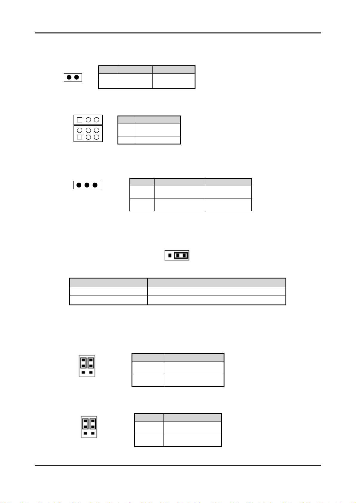
2.2.1 RS485 Terminator Select (J10)
1 2
Pin Function NOTE
ON RS485
OFF RS232 Factory
2.2.2 COMC RS232/485 Select (JP7/JP9)
JP7
JP9
Pin Function
RS232
JP7
(Factory)
JP9 RS485
2.2.3 External Battery Connector Select (J11)
1 2 3
J11
PIN Function NOTE
1-2 EXTERNAL
BATTERY
2-3 INTERNAL
BATTERY
Factory
2.2.4 Support Riser Card (JP1)
This 3-pins jumper will decide the BUS1 support a PCI CARD or a Riser Card (such AR-B1550).
1 2 3
Jumper Function
1-2 For Riser Card
2-3 Factory Preset
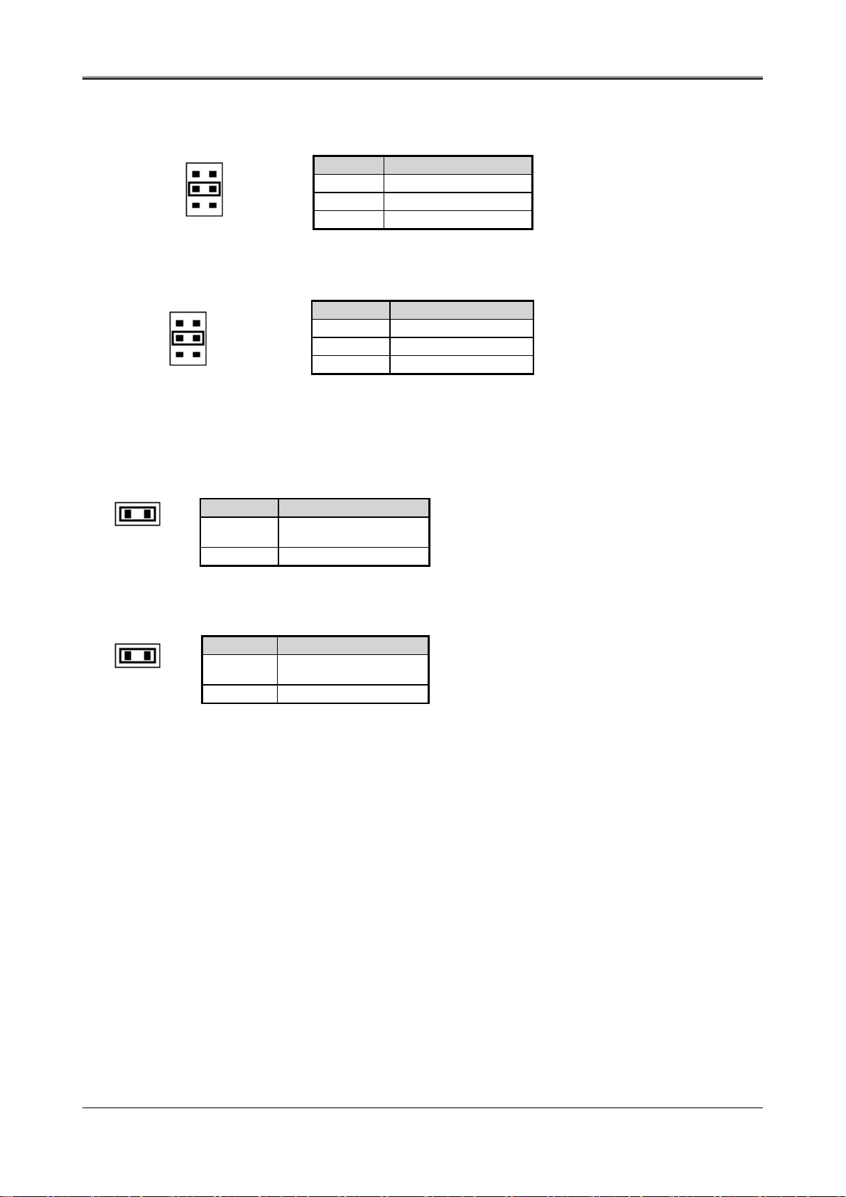
2.2.5 Voltage Select
LVDS Voltage Select (JP2)
1
3
5
2
4
6
(LCD1P) (LCD2P) Bit Voltage Select
1
3
5
2
4
6
Jumper
1-3
2-4
3-5
4-6
Jumper
1-3
2-4
3-5
4-6
VOLTAGE
VCC
(Factory Preset)
VCC3
VOLTAGE
VCC 3
(Factory Preset)
VCC
7
Page 9
AR-B1661 Manual
COM1、、、、Voltage Select (COMP1)
1
3
5
2
4
6
Jumper VOLTAGE
1-2 +12V
3-4 VCC5 (Factory)
5-6 GND
COM3、、、、Voltage Select (COMP2)
Jumper VOLTAGE
1-2 +12V
3-4 VCC5 (Factory)
5-6 GND
1
3
5
2
4
6
2.2.6 Enabled / Disabled LAN Function
# LAN1 (LAN1P)
Jumper
ON ENABLED
OFF
FUNCTION
(Factory Preset)
DISABLED
# LAN2 (LAN2P)
Jumper
ON ENABLED
OFF
FUNCTION
(Factory Preset)
DISABLED
8
Page 10

AR-B1661 Manual
2.3 CONNECTORS ON THE AR-B1661
The connectors on the AR-B1661 allows you to connect external devices such as keyboard, floppy disk drives,
hard disk drives, printers, etc. The following table lists the connectors on AR-B1661 and their respective
functions.
! COM: Serial Port A-C Connector
! LPT: Parallel Port Connector
! FDD: Floppy Drive Connector
!
USB: USB Connector
! VGA: CRT Connector
! KB: Keyboard & Mouse Connector
!
HDD: Hard Disk (IDE) Connector
! Reset
! GPIO: Bidirectional I/O
!
J1: TV-Out
!
J2: Extend LED Module/Power
!
J3: Extend LED Module/HDD
! J8: ATX PWRBTN
!
PWR1: Power Connector
!
J12, J13: Power Connector For PC104 Connector
! T.S: Touch Screen
!
J16: RS485 Signal
!
IR: Infrared Connector
! J5: EXT LAN1, LAN2 Active LED
!
AUDIO1: Audio Connector
!
LAN1, LAN2: Ethernet RJ-45 Connector
! Flat Panel LCD Connector
#
LCD1: 18-Bit LCD Connector
#
LCD2: 18-Bit LCD Connector
# LVDS: LVDS LCD Connector
#
Application For Support Dual LCD Panel
!
PC-104: X-Bus
! PCI: PCI Slot
!
Mini-PCI: Mini Connector
!
DIMM1: SDRAM Socket 168 Pin (DIMM1)
9
Page 11
AR-B1661 Manual
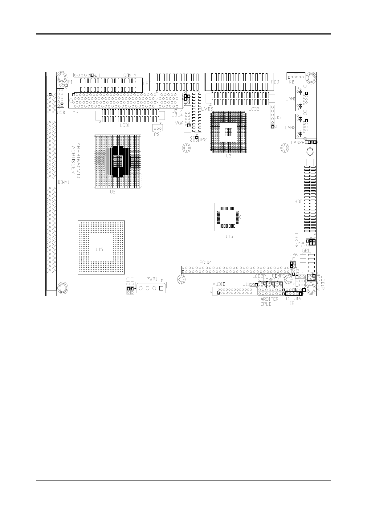
2.3.1 Connector Locations on the AR-B1661
10
Page 12

AR-B1661 Manual
2.3.2 Serial Port A~C Connector (COM)
2 34
The SERIAL PORT A~C Connector assignments are as follows:
1 33
SERIAL PORT A~C CONNECTOR (COM)
PIN Signal PIN Signal
1 –DCD1F 2 –DSR1F
3 RXD1F 4 –RTS1F
5 TXD1F 6 –CTS1F
7 –DTR1F 8 –RI1F
9 VCOM1 10 GND
11 –DCD2F 12 –DSR2F
13 RXD2F 14 –RTS2F
15 TXD2F 16 –CTS2F
17 –DTR2F 18 –RI2F
19 VCOM2 20 GND
21 –DCD3F 22 –DSR3F
23 RXD3F 24 –RTS3F
25 TXD3F 26 –CTS3F
27 –DTR3F 28 –RI3F
29 VCOM3 30 GND
31 N.C 32 N.C
33 N.C 34 N.C
2.3.3 Parallel Port Connector (LPT)
2 26
1 25
PIN Signal PIN Signal
1 -Strobe 14 -Auto Form Feed
2 Data 0 15 -Error
3 Data 1 16 -Initialize
4 Data 2 17 -Printer Select In
5 Data 3 18 Ground
6 Data 4 19 Ground
7 Data 5 20 Ground
8 Data 6 21 Ground
9 Data 7 22 Ground
10 -Acknowledge 23 Ground
11 Busy 24 Ground
12 Paper 25 Ground
13 Printer Select 26 Not Used
11
Page 13

AR-B1661 Manual
2.3.4 Floppy Drive Connector (FDD)
2 34
1 33
Pin Signal Pin Signal
1-33(odd) GROUND 18 DIRECTION
2 DRVEN 0 20 -STEP OUTPUT PULSE
4 NOT USED 22 -WRITE DATA
6 DRVEN 1 24 -WRITE GATE
8 -INDEX 26 -TRACK 0
10 -MOTOR ENABLE 0 28 -WRITE PROTECT
12 -DRIVE SELECT 1 30 -READ DATA
14 -DRIVE SELECT 0 32 -SIDE 1 SELECT
16 -MOTOR ENABLE 1 34 DISK CHANGE
2.3.5 USB Connector (USB)
2 10
1 9
Pin #
1 VCC0 6 DATA1+
2 VCC1 7 GND
3 DATA0 8 GND
4 DATA1 9 GND
5 DATA0 10 GND
Signal Name
Pin #
Signal Name
2.3.6 CRT Connector (VGA)
2 10
1 9
Pin #
1 RED 6 AGND
2 AGND 7 V.S
3 GREEN 8 DDCD
4 GND 9 H.S
5 BLUE 10 DDCK
12
Signal Name
Pin #
Signal Name
Page 14

AR-B1661 Manual
2.3.7 Keyboard & Mouse Connector (KB)
Pin # Signal Name
KB
1
6
1 MOUSE DATA
2 KB DATA
3 GND
4 VCC
5 MOUSE CLOCK
6 KB CLOCK
2.3.8 Hard Disk (IDE) Connector (HDD)
2 44
1 43
Pin Signal Pin Signal
1 -RESET 2 GROUND
3 DATA 7 4 DATA 8
5 DATA 6 6 DATA 9
7 DATA 5 8 DATA 10
9 DATA 4 10 DATA 11
11 DATA 3 12 DATA 12
13 DATA 2 14 DATA 13
15 DATA 1 16 DATA 14
17 DATA 0 18 DATA 15
19 GROUND 20 NOT USED
21 IDEDREQ 22 GROUND
23 -IOW A 24 GROUND
25 -IOR A 26 GROUND
27 IDEIORDYA 28 GROUND
29 -DACKA 30 GROUND
31 AINT 32 GROUND
33 SA 1 34 Not Used
35 SA 0 36 SA 2
37 CS 0 38 CS 1
39 HD LED A 40 GROUND
41 VCC 42 VCC
43 GROUND 44 Not Used
Hard Disk (IDE1) Connector
2.3.9 Reset
1 PWRGD
2 GND
13
Page 15

AR-B1661 Manual
2.3.10 Bidirectional I/O (GPIO)
2 10
1 9
Pin #
1 GPI0 6 GPO2
2 GPO0 7 GPI3
3 GPI1 8 GPO3
4 GPO1 9 VCC (5V)
5 GPI2 10 GND
Signal Name
Pin #
2.3.11 TV Out (J1)
1 2 3 4 5
Pin # Signal Name Pin # Signal Name
1
2
3
LUMA 4 GND
CHROMA 5 GND
COMP 6 GND
2.3.12 Extend LED Module/Power (J2)
1 2
Pin Signal
1 P/LED
2 +5V
Signal Name
2.3.13 Extend LED Module/HDD (J3)
1 2
Pin Signal
1 HLEDP
2 +5V
2.3.14 ATX PWRTBN (J8)
1 PWRBTN
2 GND
2.3.15 ATX PWR Connector (PS)
14
1 2 3
Pin Signal
1 PWRON
2 +5V
3 VCC5VSB
Page 16

AR-B1661 Manual
2.3.16 Power Connector (PWR1)
1 234
PWR1
PIN VOLTAGE
1
+12V
2
GND
3
GND
4
+5V
2.3.17 Power Connector For PC104 Connector (J12, J13)
1 2
1 2
J12
Pin Voltage
1 -12V
2 GND
J13
Pin Voltage
1 -5V
2 GND
2.3.18 Touch Screen (T.S)
1. RXDF
2. TXDF
3. GND
2.3.19 RS485 Signal (RS485)
1 2 3
Pin Signal
1
2
3
2.3.20 Infrared Connector (IR)
1 2 3 4 5
Pin Signal
1
2
3 RX
4 GND
5 TX
NET+
NET-
GND
VCC5
NC
15
Page 17

AR-B1661 Manual
2.3.21 EXT LAN1, LAN2 Active LED (J5)
1 2 3
4 5 6
Pin Signal
1
ACTLED_A
2
3 SPDLED_A
4 ACTLED_B
5 VCC3
6 SPDLED_B
VCC3
2.3.22 Audio Connector (AUDIO1)
2
26
1
25
2.3.23 Ethernet RJ-45 Connector (LAN1, LAN2)
Pin #
1
Signal Name
8
Pin #
1 TX+ 5 Not Used
2 TX- 6 RX3 RX+ 7 Not Used
4 Not Used 8 Not Used
Signal Name
2.3.24 Flat Panel LCD Connector
# 18-Bit LCD Connector (LCD1)
2 44
1 43
Pin #
1 GND 23 G4
2 FPSCLK 24 G5
3 GND 25 NC
4 HSYNC 26 NC
5 VSYNC 27 GND
6 GND 28 R0
7 NC 29 R1
8 NC 30 R2
9 B0 31 R3
10 B1 32 R4
11 B2 33 R5
12 B3 34 GND
13 GND 35 LCDVDD
14 B4 36 LCDVDD
15 B5 37 +12V
16 NC 38 +12V
17 NC 39 GND
18 G0 40 GND
19 G1 41 FPEN
20 GND 42 DE
21 G2 43 VBIASEN
22 G3 44 VDDEN
Signal Name
Pin #
Signal Name
16
Page 18

AR-B1661 Manual
# 18-Bit LCD Connector (LCD2)
2 44
1 43
Pin # Signal Name Pin # Signal Name
1 GND 23 G6
2 FPSCLK 24 G7
3 GND 25 R0
4 HSYNC 26 R1
5 VSYNC 27 GND
6 GND 28 R2
7 B0 29 R3
8 B1 30 R4
9 B2 31 R5
10 B3 32 R6
11 B4 33 R7
12 B5 34 GND
13 GND 35 LCDVDD
14 B6 36 LCDVDD
15 B7 37 +12V
16 G0 38 +12V
17 G1 39 GND
18 G2 40 GND
19 G3 41 FPEN
20 GND 42 DE
21 G4 43 VBIASEN
22 G5 44 VDDEN
# LVDS LCD Connector (LVDS)
2 26
1 25
Pin #
10 NC 23 VTX5
11 TXOUT2+ 24 NC
12 GND 25 VTX5
13 TXCLK- 26 NC
Signal Name
1 TXOUT0- 14 GND
2 GND 15 TXCLK+
3 TXOUT0+ 16 VTX12
4 GND 17 TXOUT3-
5 TXOUT1- 18 VTX12
6 VTX5 19 TXOUT3+
7 TXOUT1+ 20 GND
8 VTX5 21 VTKBP
9 TXOUT2- 22 NC
Pin #
Signal Name
17
Page 19

AR-B1661 Manual
A
2.3.25 X-Bus (PC-104)
Support 8-Bit ISA Interface
B1
□□□□□□□□□□□□□□□□□□□□□□□□□□□□□□□□
□□□□□□□□□□□□□□□□□□□□□□□□□□□□□□□□
1 A32
Pin # Signal Name Pin # Signal Name
A1 IOCHK# B1 GND
A2 SD7 B2 RSTDRV
A3 SD6 B3 VCC
A4 SD5 B4 IRQ9
A5 SD4 B5 -5V
A6 SD3 B6 DREQ2
A7 SD2 B7 -12V
A8 SD1 B8 ZWS#
A9 SD0 B9 +12V
A10 IOCHRDY B10 GND
A11 AEN B11 SMEMW#
A12 SA19 B12 SMEMR#
A13 SA18 B13 IOW#
A14 SA17 B14 IOR#
A15 SA16 B15 DACK3#
A16 SA15 B16 DREQ3
A17 SA14 B17 DACK1#
A18 SA13 B18 DREQ1
A19 SA12 B19 REFRESH#
A20 SA11 B20 SYSCLK
A21 SA10 B21 IRQ7
A22 SA9 B22 IRQ6
A23 SA8 B23 IRQ5
A24 SA7 B24 IRQ4
A25 SA6 B25 IRQ3
A26 SA5 B26 DACK2#
A27 SA4 B27 TC
A28 SA3 B28 BALE
A29 SA2 B29 VCC
A30 SA1 B30 OSC
A31 SA0 B31 GND
A32 GND B32 GND
★ C1~C20 & D1~D20 : NO SIGNAL
2.3.26 PCI Slot (PCI)
2.3.27 Mini Connector (Mini-PCI)
2.3.28 SDRAM Socket 168 Pin (DIMM1)
18
Page 20

AR-B1661 Manual
2.4 WATCHDOG TIMER CONFIGURATION
The function of the watchdog timer is to reset the system automatically and is defined at I/O port 0443H. To
enable disable the watchdog timer and allow the system to reset, the timer has a tolerance of 20% for its
intervals.
Read/Write Address:443H
8 7 6 5 4 3 2 1 0
E/D RESET Define Timing
Bit6:1 The setting time 1~61seconds。
Bit7 1=Enable Reset。
0=Disable Reset。
Bit8 1=Enable Watchdog。
0=Disable Watchdog。
19
Page 21

AR-B1661 Manual
3. BIOS CONFIGURATION
This chapter describes the different settings available in the Award BIOS that comes with the AR-B1661 CPU card.
The topics covered in this chapter are as follows:
! BIOS Introduction
! BIOS Setup
! Standard CMOS Features
! Advanced Chipset Features
! Integrated Peripherals
! Power Management Setup
! PNP/PCI Configuration
! Load Fail-Safe Defaults
! Load Optimized Defaults
! Set Supervisor Password
! Set User Password
! Save & Exit Setup
! Exit Without Saving
3.1 BIOS INTRODUCTION
The Award BIOS (Basic Input/Output System) installed in your computer system’s ROM supports Intel Pentium II
processors in a standard IBM-AT compatible I/O system. The BIOS provides critical low-level support for a
standard device such as disk drives, serial ports and parallel ports. It also adds virus and password protection as
well as special support for detailed fine-tuning of the chipset controlling the entire system.
3.2 BIOS SETUP
The Award BIOS provides a Setup utility program for specifying the system configurations and settings. The
BIOS ROM of the system stores the Setup utility. When you turn on the computer, the Award BIOS is
immediately activated. Pressing the <Del> key immediately allows you to enter the Setup utility. If you are a little
bit late pressing the <Del> key, POST (Power On Self Test) will continue with its test routines, thus preventing
you from invoking the Setup. If you still wish to enter Setup, restart the system by pressing the ”Reset” button or
simultaneously pressing the <Ctrl>, <Alt> and <Delete> keys. You can also restart by turning the system Off and
back On again. The following message will appear on the screen:
Press <DEL> to Enter Setup
In general, you press the arrow keys to highlight items, <Enter> to select, the <PgUp> and <PgDn> keys to
change entries, <F1> for help and <Esc> to quit.
When you enter the Setup utility, the Main Menu screen will appear on the screen. The Main Menu allows you to
select from various setup functions and exit choices.
Phoenix-Award BIOS CMOS Setup Utility
STANDARD CMOS FEATURES
ADVANCED BIOS FEATURES LOAD OPTIMIZED DEFAULTS
ADVANCED CHIPSET FEATURES SET SUPERVISOR PASSWORD
INTEGRATED PERIPHERALS ISET USER PASSWORD
POWER MANAGEMENT SETUP SAVE & EXIT SETUP
PNP/PCI CONFIGURATIONS EXIT WITHOUT SAVING
ESC : Quit F9 : Menu in Bios $ % & ' : Select Item
F10 : Save & Exit Setup (Shift) F2 : Change Color
Time, Date, Hard Disk Type……….
LOAD FAIL-SAFE DEFAULTS
20
Page 22

AR-B1661 Manual
The section below the setup items of the Main Menu displays the control keys for this menu. At the bottom of the
Main Menu just below the control keys section, there is another section, which displays information on the
currently highlighted item in the list.
NOTE:
If your computer cannot boot after making and saving system changes with Setup, the Award BIOS
supports an override to the CMOS settings that resets your system to its default.
We strongly recommend that you avoid making any changes to the chipset defaults. These defaults
have been carefully chosen by both Award and your system manufacturer to provide the absolute
maximum performance and reliability.
3.3 STANDARD CMOS FEATURES
The “Standard CMOS Setup” choice allows you to record some basic hardware configurations in your computer
system and set the system clock and error handling. If the motherboard is already installed in a working system,
you will not need to select this option. You will need to run the Standard CMOS option, however, if you change
your system hardware configurations, the onboard battery fails, or the configuration stored in the CMOS memory
was lost or damaged.
At the bottom of the menu are the control keys for use on this menu. If you need any help in each item field, you
can press the <F1> key. It will display the relevant information to help you. The memory display at the lower
right-hand side of the menu is read-only. It will adjust automatically according to the memory changed. The
following describes each item of this menu.
Date
The date format is:
Day: Sun to Sat
Month: 1 to 12
Date: 1 to 31
Year: 2002 to 2102
To set the date, highlight the “Date” field and use the PageUp/ PageDown or +/- keys to set the current time.
Time
The time format is: Hour: 00 to 23
Minute: 00 to 59
Second: 00 to 59
To set the time, highlight the “Time” field and use the <PgUp>/ <PgDn> or +/- keys to set the current time.
21
Page 23

AR-B1661 Manual
Primary HDDs
The onboard IDE connectors provide Primary channels for connecting up to four IDE hard disks or other IDE
devices. Each channel can support up to two hard disks; the first is the “Master” and the second is the “Slave”.
To enter the specifications for a hard disk drive, you must select first a “Type”. There are 45 predefined types
and 4 user definable types are for Enhanced IDE BIOS. Type 1 to 45 is predefined. Type “User” is user-definable.
For the Primary Master/Slave as well as Secondary Master/Slave, you can select “Auto” under the TYPE and
MODE fields. This will enable auto detection of your IDE drives and CD-ROM drive during POST.
Press <PgUp>/<PgDn> to select a numbered hard disk type or type the number and press the <Enter> key. The
hard disk will not work properly if you enter incorrect information for this field. If your hard disk drive type is not
matched or listed, you can use Type User to define your own drive type manually. If you select Type User, the
related information has to be entered to the following items.
CYLINDER: Number of cylinders
HEAD: Number of read/write heads
PRECOMP: Write precompensation
LANDING ZONE: Landing zone
SECTOR: Number of sectors
MODE (for IDE HDD only): Auto
Normal (HD < 528MB)
Large (for MS-DOS only)
NOTE:
The specifications of your drive must match with the drive table. The hard disk will not work properly
if you enter incorrect information in these fields. If your hard disk drive type is not matched or listed,
you can use Type User to define your own drive type manually.
LBA (HD > 528MB and supports Logical Block Addressing)
Drive A / Drive B
These fields identify the types of floppy disk drive A or drive B that has been installed in the computer. The
available specifications are:
360KB
5.25 in.
1.2MB
5.25 in.
720KB
3.5 in.
1.44MB
3.5 in.
2.88MB
3.5 in.
LCD & CRT
This field selects the type of video display card installed in your system. You can choose the following video
display cards:
Both: LCD & CRT
LCD: LCD Only
CRT: CRT Only
Halt On
This field determines whether the system will halt if an error is detected during power up.
No errors The system boot will not be halted for any error that may be detected. (Default)
All errors Whenever the BIOS detect a non-fatal error, the system will stop and you will be
prompted.
All, But Keyboard The system boot will not be halted for a keyboard error; it will stop for all other errors
All, But Diskette The system boot will not be halted for a disk error; it will stop for all other errors.
All, But Disk/Key The system boot will not be halted for a key- board or disk error; it will stop for all
others.
Flat Panel Resolution
140 × 480
800 × 600
1024 × 768
22
Page 24

AR-B1661 Manual
3.4 ADVANCE D BIOS FEATURES
This section allows you to configure and improve your system and allows you to set up some system features
according to your preference.
Virus Warning
This item protects the boot sector and partition table of your hard disk against accidental modifications. If an
attempt is made, the BIOS will halt the system and display a warning message. If this occurs, you can either
allow the operation to continue or run an anti-virus program to locate and remove the problem.
NOTE:
Many disk diagnostic programs, which attempt to access the boot sector table, can cause the virus
warning. If you will run such a program, disable the Virus Warning feature.
CPU Internal Cache
Cache memory is additional memory that is much faster than conventional DRAM (system memory). CPUs from
486-type on up contain internal cache memory, and most, but not all, modern PCs have additional (external)
cache memory. When the CPU requests data, the system transfers the requested data from the main DRAM into
cache memory, for even faster access by the CPU. These items allow you to enable (speed up memory access)
or disable the cache function. By default, these items are Enabled.
CPU L2 Cache ECC Checking
When enabled, this allows ECC checking of the CPU’s L2 cache. By default, this field is Enabled.
Quick Power On Self Test
When enabled, this field speeds up the Power On Self Test (POST) after the system is turned on. If it is set to
Enabled, BIOS will skip some items.
Boot Sequence
This field determines the drive that the system searches first for an operating system. The options are:
A, C, SCSI D, A, SCSI SCSI, C, A
C, A, SCSI E, A, SCSI C only
C, CDROM, A F, A, SCSI LS/ZIP, C
CDROM, C, A SCSI, A, C
The default value is Floppy, HDD-O, CDROM.
23
Page 25

AR-B1661 Manual
Swap Floppy Drive
This item allows you to determine whether or not to enable Swap Floppy Drive. When enabled, the BIOS swaps
floppy drive assignments so that Drive A becomes Drive B, and Drive B becomes Drive A. By default, this field is
set to Disabled.
Boot Up Floppy Seek
When enabled, the BIOS will seek whether or not the floppy drive installed has 40 or 80 tracks. 360K type has
40 tracks while 760K, 1.2M and 1.44M all have 80 tracks. By default, this field is set to Enabled.
Boot Up NumLock Status
This allows you to activate the NumLock function after you power up the system. By default, the system boots up
with NumLock On.
Boot Up System Speed
This has no function and selects the default system speed (High).
Gate A20 Option
This field allows you to select how Gate A20 is worked. Gate A20 is a device used to address memory above 1
MB. The default setting is Fast.
Typematic Rate Setting
When disabled, continually holding down a key on your keyboard will generate only one instance. When enabled,
you can set the two typematic controls listed next. By default, this field is set to Disabled.
Typematic Rate (Chars/Sec)
When the typematic rate is enabled, the system registers repeated keystrokes speeds. You can select speed
range from 6 to 30 characters per second. By default, this item is set to 6.
Typematic Delay (Msec)
When the typematic rate is enabled, this item allows you to set the time interval for displaying the first and
second characters. By default, this item is set to 250msec.
Security Option
This field allows you to limit access to the System and Setup. The default value is Setup. When you select
System, the system prompts for the User Password every time you boot up. When you select Setup, the system
always boots up and prompts for the Supervisor Password only when the Setup utility is called up.
OS Select for DRAM > 64MB
This option allows the system to access greater than 64MB of DRAM memory when used with OS/2 that
depends on certain BIOS calls to access memory. The default setting is Non-OS/2.
Report No FDD For WIN 95
This option allows Windows 95 to share with other peripherals IRQ6 that is assigned to a floppy disk drive if the
drive does not exist. The default setting is No.
Video BIOS Shadow
This item allows you to change the Video BIOS location from ROM to RAM. Video Shadow will increase the
video speed.
24
Page 26

AR-B1661 Manual
3.5 ADVANCED CHIPSET FEATURES
This Setup menu controls the configuration of the motherboard chipset.
Auto Configuration
This field predefines values for DRAM, cache timing according to CPU type and system clock. When this field is
enabled, the predefined items will become read-only.
SDRAM RAS-to-CAS Delay
When DRAM is refreshed, both rows and columns are addressed separately. This field allows you to determine
the timing of transition from Row Address Strove (RAS) to Column Address Strobe (CAS). The default setting is
3.
SDRAM RAS Precharge Time
The precharge time is the number of cycles it takes for the RAS to accumulate its charge before DRAM
refreshes. If insufficient time is allowed, refresh may be incomplete and the DRAM may fail to retain data. The
default setting is 3.
SDRAM CAS Latency Time
When synchronous DRAM is installed, the number of clock cycles of CAS latency depends on the DRAM timing.
Do not reset this field from the default value specified by the system designer. The default setting is 3.
System BIOS Cacheable
When enabled, access to the system BIOS ROM addressed at F0000H-FFFFFH is cached, provided that the
cache controller is disabled.
25
Page 27

AR-B1661 Manual
Video RAM Cacheable
Selecting Enabled allows caching of the video BIOS ROM at C0000h to C7FFFh, resulting in better video
performance. However, if any program writes to this memory area, a memory access error may result.
8 Bit I/O Recovery Time
This option specifies the length of the delay (in sysclks) inserted between consecutive 8-bit I/O operations. The
settings are 1, 2, 3, 4, 5, 6, 7, or 8. The default setting is 3.
16 Bit I/O Recovery Time
This option specifies the length of the delay (in sysclks) inserted between consecutive 16-bit I/O operations. The
settings are 1, 2, 3, 4, 5, 6, 7, or 8. The default setting is 2.
Memory Hole at 15MB - 16MB
In order to improve performance, certain space in memory can be reserved for ISA cards. This field allows you to
reserve 15MB to 16MB of memory address space to ISA expansion cards. This makes memory from 15MB and
up unavailable to the system. Expansion cards can only access memory up to 16MB. By default, this field is set
to Disabled.
Passive Release
When enabled, CPU to PCI bus accesses is allowed during passive release. Otherwise, the arbiter only accepts
another PCI master access to local DRAM.
Delayed Transaction
The chipset has an embedded 32-bit posted write buffer to support delay transactions cycles. Select Enabled to
support compliance with PCI specification version 2.1. The default setting is Disabled.
AGP Aperture Size (MB)
The field sets aperture size of the graphics. The aperture is a portion of the PCI memory address range
dedicated for graphics memory address space. Host cycles that hit the aperture range are forwarded to the AGP
without any translation. The options available are 4M, 8M, 16M, 32M, 64M, 128M and 256M. The default setting
is 64M.
Power-Supply Type
To select your power supply Type AT/FFATX.
26
Page 28

AR-B1661 Manual
3.6 INTEGRATED PERIPHERALS
This option sets your hard disk configuration, mode and port.
IDE Primary/Secondary Master/Slave PIO
These fields allow your system hard disk controller to work faster. Rather than have the BIOS issue a series of
commands that transfer to or from the disk drive, PIO (Programmed Input/Output) allows the BIOS to
communicate with the controller and CPU directly.
The system supports five modes, numbered from 0 (default) to 4, which primarily differ in timing. When Auto is
selected, the BIOS will select the best available mode.
IDE Primary/Secondary Master/Slave UDMA
These fields allow your system to improve disk I/O throughput to 33Mb/sec with the Ultra DMA/33 feature. The
options are Auto and Disabled.
On-Chip Primary/Secondary PCI IDE
The integrated peripheral controller contains an IDE interface with support for two IDE channels. Select Enabled
to activate each channel separately.
USB Keyboard Support
Select Enabled if your system contains a Universal Serial Bus (USB) controller and you have a USB keyboard.
Onboard Serial/Parallel Port
These fields allow you to select the onboard serial and parallel ports and their addresses. The default values for
these ports are:
Serial Port 1 3F8/IRQ4
Serial Port 2 2F8/IRQ3
Parallel Port 378H/IRQ7
Serial Port 3 3E8/IRQ5
UART Mode Select
This field determines the UART mode in your computer. The settings are Normal, IrDA and ASKIR. The default
value is Normal.
Parallel Port Mode
This field allows you to determine parallel port mode function.
SPP Normal Printer Port
EPP Enhanced Parallel Port
ECP Extended Capabilities Port
27
Page 29

AR-B1661 Manual
3.7 POWER MANAGEMENT SETUP
The Power Management Setup allows you to save energy of your system effectively. It will shut down the hard
disk and turn off video display after a period of inactivity.
ACPI
When using AT power, please select Disable.
Power Management
This field allows you to select the type of power saving management modes. There are four selections for Power
Management.
Min. Power Saving Minimum power management
Max. Power Saving Maximum power management.
User Define Each of the ranges is from 1 min. to 1hr. Except
for HDD Power Down, which ranges from 1 min.
to 15 min.
(Default)
NOTE:
In order to enable the CPU overheat protection feature, the Power Management field should not be
set to Disabled.
PM Control by APM
This field allows you to use the Advanced Power Management device to enhance the Max. Power Saving mode
and stop the CPU’s internal clock. If the Max. Power Saving is not enabled, this will be preset to NO.
Video Off Method
This field defines the Video Off features. There are three options.
V/H SYNC + Blank Default setting, blank the screen and turn off vertical and horizontal scanning.
DPMS Allows the BIOS to control the video display card if it supports the DPMS feature.
Blank Screen This option only writes blanks to the video buffer.
Video Off After
As the system moves from lesser to greater power-saving modes, select the mode in which you want the monitor
to blank.
28
Page 30

AR-B1661 Manual
Modem Use IRQ
This field names the interrupt request (IRQ) line assigned to the modem (if any) on your system. Activity of the
selected IRQ always awakens the system. By default, the IRQ is set to 3.
Doze Mode
When enabled, and after the set time of system inactivity, the CPU clock will run at a slower speed while all other
devices still operate at full speed.
Standby Mode
After the selected period of system inactivity, the fixed disk drive and the video shut off while all other devices
still operate at full speed.
Suspend Mode
When enabled, and also after the set time of system inactivity, all devices except the CPU will be shut off.
HDD Power Down
When enabled, and after the set time of system inactivity, the hard disk drive will be powered down while all
other devices remain active.
Throttle Duty Cycle
When the system enters Doze mode, the CPU clock runs only part of the time. You may select the percent of
time that the clock runs.
VGA Active Monitor
When enabled, any video activity restarts the global timer for Standby mode. The default setting is Enabled.
Soft-Off by PWR-BTTN
This field defines the power-off mode when using an ATX power supply. The Instant-Off mode allows powering
off immediately upon pressing the power button. In the Delay 4 Sec mode, the system powers off when the
power button is pressed for more than four seconds or places the system in a very low-power-usage state, with
only enough circuitry receiving power to detect power button activity or Resume by Ring activity (see next field)
when pressed for less than 4 seconds. The default value is Instant-Off.
IRQ 8 Break Suspend
You can enable or disable the monitoring of IRQ 8 (Real Time Clock) so it does not awaken the system from
Suspend mode.
29
Page 31

AR-B1661 Manual
3.8 PNP/PCI CONFIGURATION
This option configures the PCI bus system. All PCI bus systems on the system use INT#, thus all installed PCI
cards must be set to this value.
Phoenix-Award BIOS CMOS Setup Utility
PNP/PCI Configuration
PNP OS Installed : No Used MEM base addr : N/A
Resources Controlled by : Manual
Reset Configuration Data : Disabled
IRQ-3 assigned to : Legacy ISA
IRQ-4 assigned to : Legacy ISA
IRQ-5 assigned to : PCI/ISA PnP
IRQ-7 assigned to : Legacy ISA
IRQ-9 assigned to : PCI/ISA PnP
IRQ-10 assigned to : PCI/ISA PnP
IRQ-11 assigned to : PCI/ISA PnP
IRQ-12 assigned to : PCI/ISA PnP
IRQ-14 assigned to : PCI/ISA PnP
IRQ-15 assigned to : PCI/ISA PnP
DMA-0 assigned to : PCI/ISA PnP
DMA-1 assigned to : PCI/ISA PnP ESC : Quit $ % ' : Select Item
DMA-3 assigned to : PCI/ISA PnP F1 : Help PU/PD/+/- : Modify
DMA-5 assigned to : PCI/ISA PnP F5 : Old Values (Shift) F2 : Color
DMA-6 assigned to : PCI/ISA PnP F6 : Load BIOS Defaults
DMA-7 assigned to : PCI/ISA PnP F7 : Load Setup Defaults
PNP OS Installed
This field allows you to specify if the operating system installed in your system is plug and play aware.
NOTE:
Operating systems such as DOS, OS/2, and Windows 3.x do not use PnP
Reset Configuration Data
This field allows you to determine whether or not to reset the configuration data. The default value is Disabled.
Resources Controlled by
This PnP BIOS can configure all of the boot and compatible devices automatically. However, this capability
needs you to use a PnP operating system such as Windows 95. The default value is Manual.
IRQ3/4/5/7/9/10/11/12/14/15, DMA0/1/3/5/6/7 assigned to
These fields allow you to determine the IRQ/DMA assigned to the ISA bus and is not available to any PCI slot.
PCI /VGA Palette Snoop
30
Page 32

AR-B1661 Manual
3.9 LOAD FAIL-SAFE DEFAULTS
This option allows you to load the troubleshooting default values permanently stored in the BIOS ROM. These
default settings are non-optimal and disable all high-performance features.
Phoenix-Award BIOS CMOS Setup Utility
STANDARD CMOS FEATURES LOAD FAIL-SAFE DEFAULTS
ADVANCED BIOS FEATURES LOAD OPTIMIZED DEFAULTS
ADVANCED CHIPSET FEATURES SET SUPERVISOR PASSWORD
INTEGRATED PERIPHERALS SET USER PASSWORD
POWER MANAGEMENT SETUP SAVE & EXIT SETUP
PNP/PCI CONFIGURATION EXIT WITHOUT SAVING
ESC : Quit F9 : Menu in BIOS $ % & ' : Select Item
F10 : Save & Exit Setup
Load Fail-Safe Defaults (Y/N)? N
Load Fail-Safe Defaults
To load BIOS defaults value to CMOS SRAM, enter “Y”. If not, enter “N”.
3.10 LOAD OPTIMIZED DEFAULTS
This option allows you to load the default values to your system configuration. These default settings are optimal
and enable all high performance features.
Phoenix-Award BIOS CMOS Setup Utility
STANDARD CMOS FEATURES LOAD FAIL-SAFE DEFAULTS
ADVANCED BIOS FEATURES LOAD OPTIMIZED DEFAULTS
ADVANCED CHIPSET FEATURES SET SUPERVISOR PASSWORD
INTEGRATED PERIPHERALS SET USER PASSWORD
POWER MANAGEMENT SETUP SAVE & EXIT SETUP
PNP/PCI CONFIGURATION EXIT WITHOUT SAVING
ESC : Quit F9: Menu in BIOS $ % & ' : Select Item
F10 : Save & Exit Setup
Load Optimized Defaults (Y/N)? N
Load Optimized Defaults
To load SETUP defaults value to CMOS SRAM, enter “Y”. If not, enter “N”.
31
Page 33

AR-B1661 Manual
3.11 SUPERVISOR / USER PASSWORD
These two options set the system password. Supervisor Password sets a password that will be used to protect
the system and Setup utility. User Password sets a password that will be used exclusively on the system. To
specify a password, highlight the type you want and press <Enter>. The Enter Password: message prompts on
the screen. Type the password, up to eight characters in length, and press <Enter>. The system confirms your
password by asking you to type it again. After setting a password, the screen automatically returns to the main
screen.
To disable a password, just press the <Enter> key when you are prompted to enter the password. A message
will confirm the password to be disabled. Once the password is disabled, the system will boot and you can enter
Setup freely.
Phoenix-Award BIOS CMOS Setup Utility
STANDARD CMOS FEATURES LOAD FAIL-SAFE DEFAULTS
ADVANCED BIOS FEATURES LOAD OPTIMIZED DEFAULTS
ADVANCED CHIPSET FEATURES SET SUPERVISOR PASSWORD
INTEGRATED PERIPHERALS SET USER PASSWORD
POWER MANAGEMENT SETUP SAVE & EXIT SETUP
PNP/PCI CONFIGURATION EXIT WITHOUT SAVING
ESC : Quit F9: Menu in BIOS $ % & ' : Select Item
F10 : Save & Exit Setup
Enter Password:
Change / Set / Disable Password
3.12 IDE HDD AUTO DETECTION
This option detects the parameters of an IDE hard disk drive, and automatically enters them into the Standard
CMOS Setup screen.
Up to four IDE drives can be detected, with parameters for each appearing in sequence inside a box. To accept
the displayed entries, press the “Y” key; to skip to the next drive, press the “N” key. If you accept the values, the
parameters will appear listed beside the drive letter on the screen.
32
Page 34

AR-B1661 Manual
3.13 SAVE & EXIT SETUP
This option allows you to determine whether to accept the modifications or not. If you type “Y”, you will quit the
setup utility and save all changes into the CMOS memory. If you type “N”, you will return to Setup utility.
STANDARD CMOS FEATURES LOAD FAIL-SAFE DEFAULTS
ADVANCED BIOS FEATURES LOAD OPTIMIZED DEFAULTS
ADVANCED CHIPSET FEATURES SET SUPERVISOR PASSWORD
INTEGRATED PERIPHERALS SET USER PASSWORD
POWER MANAGEMENT SETUP SAVE & EXIT SETUP
PNP/PCI CONFIGURATION EXIT WITHOUT SAVING
ESC : Quit F9: Menu in BIOS $ % & ' : Select Item
F10 : Save & Exit Setup
Phoenix-Award BIOS CMOS Setup Utility
Save to CMOS and Exit (Y/N)? N
Save Data to CMOS
3.14 EXIT WITHOUT SAVING
Select this option to exit the Setup utility without saving the changes you have made in this session. Typing “Y”
will quit the Setup utility without saving the modifications. Typing “N” will return you to Setup utility.
Phoenix-Award BIOS CMOS Setup Utility
STANDARD CMOS FEATURES LOAD FAIL-SAFE DEFAULTS
ADVANCED BIOS FEATURES LOAD OPTIMIZED DEFAULTS
ADVANCED CHIPSET FEATURES SET SUPERVISOR PASSWORD
INTEGRATED PERIPHERALS SET USER PASSWORD
POWER MANAGEMENT SETUP SAVE & EXIT SETUP
PNP/PCI CONFIGURATION EXIT WITHOUT SAVING
ESC : Quit F9: Menu in BIOS $ % & ' : Select Item
F10 : Save & Exit Setup
Quit Without Saving (Y/N)? N
Abandon all Data
33
Page 35

AR-B1686 User’s Guide
SMI721 CHIP DRIVER INSTALL GUIDE
FOR WINDIOWS98 (ENGLISH)
STEP1:
VGA / DUAL_DISPLAY / CONTROLPANEL / English / Disk1 / Setup.exe
:Double click to running SMI721 Control Panel Setup.
::
STEP2:
Start→Setting→Control Panel→System Propertris→Display Adapter →Driver→Update Driver→WIN9XME
:Reinstall driver for Display Adapter.
::
34
Page 36

AR-B1686 User’s Guide
HOW TO SET DUALPANEL
Choose second display and click extend my Windows Desktop onto this monitor.
Note:
If the content in Setting is inconsistent with CD-ROM, please refer to the Setting as priority.
35
 Loading...