

Page 1
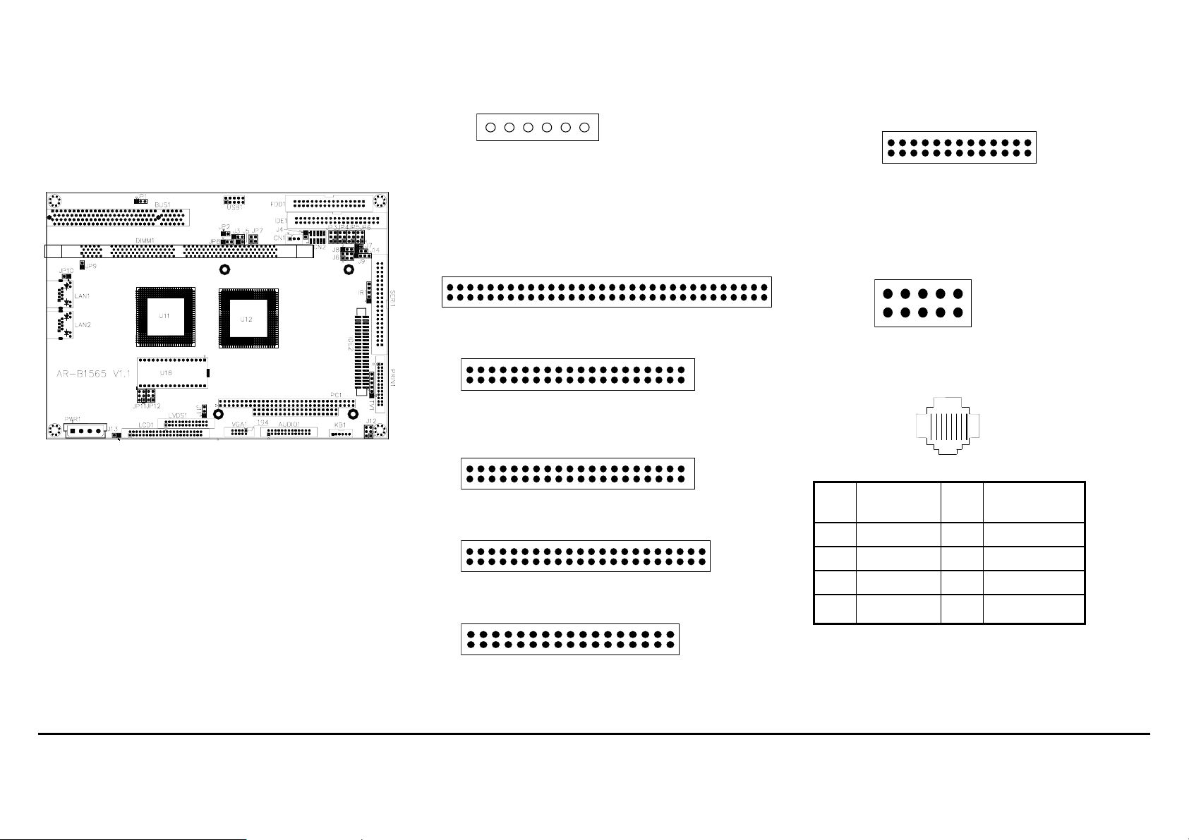
6. PARALLEL PORT CONNECTOR (PRIN1)
2 26
1
25
Parallel Port Connector
7. CRT CONNECTOR (VGA1)
2
19
10
6. RED
7. GND
8. GREEN
9. GND
10. BLUE
1. GND
2. V.S
3. DDCK
4. H.S
5. DDCD
AR-B1565/1565A Manual
Edition 1.11
2. KEYBOARD & MOUSE CONNECTOR (KB1)
KB1
12
1. MOUSE DATA
2. KB DATA
3. GND
4. VCC
5. MOUSE CLOCK
6. KB CLOCK
3. PC/104 CONNECTOR (PC 1)
(1) 64 Pin PC/104 Connector A&B
2 64
1
(2) 40 Pin PC/104 Connector C&D
2 40
63
8. ETHERNET RJ-45 CONNECTOR (LAN1, LAN2)
1
39
18
4. HARD DISK (IDE) CONNECTOR (IDE1, IDE2)
B
1.1 PACKING LIST
z The quick setup manual
z 1 AR-B1565 CPU board
z 2 Hard disk drive adapter cable
z 1 Floppy disk drive adapter cable
z 1 Parallel port adapter cable mounted on one bracket
z 1 Software utility CD
z 4 RS-232 and PS/2 Mouse & Keyboard interface cable
mounted on bracket
(1) 40 Pin Hard Disk Connector (IDE1)
2 40
1
(2) 44 Pin Hard Disk Connector (IDE2)
2 44
1
5. FDD PORT CONNECTOR (FDD1)
2 34
1
33
39
43
PIN FUNCTION PIN ASSIGNMENT
1 TPTX+ 5 NOT USED
2 TPTX+ 6 TPRX3 TPRX+ 7 NOT USED
4 NOT USED 8 NOT USED
Page 1 of 4 AR-B1565/1565A Manual
Part No: 220010111
Page 2
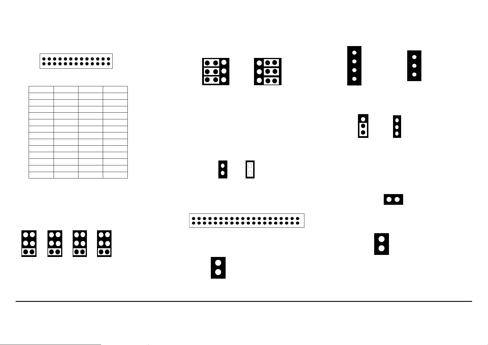
9. 26-PIN A U DIO CONNECTOR (AUDIO1)
r
2
1
25
26
PIN Signal PIN Signal
1 AUXAL 2 LINEL
3 AUXAR 4 LINER
5 VCC 6 Not Used
7 AUDIOL 8 MICPH
9 AUDIOR 10 PCSPKO
11 GND 12 GND
13 Not Used 14 Not Used
15 GND 16 GND
17 Not Used 18 Not Used
19 Not Used 20 Not Used
21 Not Used 22 Not Used
23 Not Used 24 Not Used
25 GND 26 GND
Note: the connector does not contain the GAME (MIDI)
port signal. When AR-B9425 aud io card is used with this
CPU board, the GAME port function is not supported.
10. SERIAL PORT A~D SELECT (JP3~JP6)
1
3
5
2
1
4
3
6
5
2
1
4
3
6
5
2
1
4
3
6
5
2
1-2 +5V
3-4 +12V
4
5-6 GND
6
(3-4 +12V: Factory Preset)
11. COM-C RS-232/RS-485 SELECT (J6, J8)
J6
1
3
5
RS-232
J8
J6
1
1
3
2
5
3
J8
1
2
3
RS-485
Factory Preset
12. RS-485 TERMINATOR SELECT (J7)
When there is only one line the setting should be left off,
if multiple blocks are used on a single line this should be
set to “ON” in order to properly terminate the connection
for better transmission of data
1
2
OFF
1
2
ON
Factory Preset
13. SERIAL PORT A-D CONNECTOR (SERI1)
2
1
14. RESET SWITCH (J13)
2 – RS
1 - GND
39
40
15. POWER CONNECTOR (PWR1, J11)
1: +12V
1
2
3
4
2: GND
3: GND
4: +5V
PWR1
1
2
3
1: GND
2: -5V
3: -12V
J11
16. POWER CONTROL CONNECTOR (CN1)
1
2
3
for AT Powe
1
2
3
for ATX P o wer
PSON
+5VSB
Factory Preset
17. POWER ON CONNECTOR FOR ATX POWER
SUPPLY (J4)
GND
2 1
PSON
18. EXT.BATTERY (J5)
1 – EXBAT
2 - GND
Page 2 of 4 AR-B1565/1565A Manual
Part No: 220010111
Page 3

19. BATTERY JUMPER (JP8)
2
Y
Y
1
1-2:EXTERNAL BATTER
2-3:ON-BOARD BA TTE R
3
Factory Preset
20. INFRARED CONNECTOR (IR1)
1 5
1. VCC
2. NC
3. IR DATA RECEIVER
4. GND
5. IR DATA TRANSFER
21. PCI SELECT (JP1)
1
2
3
2-3 Support one PCI Card
(Factory preset)
1-2 When riser card is applied
Factory Preset
22. LED HEADER (J12)
1 3 5
1.HLEDP+
2.HLEDP-
3.HLEDS+
HLEDP: External LED connector for primary IDE channel.
HLEDS: External LED connector for secondary IDE
P/WLED: External LED connector for power status
2 4 6
channel.
indication.
4.HLEDS-
5.P/WLED+
6.P/WLED-
23. LCD CONNECTOR (LCD1)
Only for AR-B1565
The pin assignment of LCD connector is shown below:
2
1
LCD Display Connector
Pin Signal Pin Signal
1 GND 2 SHFCLK
3 GND 4 LP
5 FLM 6 GND
7 NC 8 NC
9 P0 (B0) 10 P1 (B1)
11 P2 (B2) 12 P3 (B3)
13 GND 14 DB2 (B4)
15 P5 (B5) 16 NC
17 NC 18 P6 (G0)
19 P7 (G1) 20 GND
21 P8 (G2) 22 P9 ( G3)
23 P10 (G4) 24 P11 (G5)
25 NC 26 NC
27 GND 28 P12 (R0)
29 P13 (R1) 30 P14 (R2)
31 P15 (R3) 32 P16 (R4)
33 P17 (R5 ) 34 GND
35 VCC 36 VCC
37 +12V 38 +12V
39 GND 40 GND
41 DE 42 ENABLK
43 GND 44 VEE
24. TOUCH SCREEN CONNECTOR (J3)
1 2 3
1 RXDF
2 TXDF
3 CGND
25. EXTERNAL SPEAKER HEADER (J9)
1 Vcc
2 X
3 INT BZ
4 BUZ Z
3-4 On
Enable Internal Buzzer
Enable External Buzzer
Factory Preset
26. LCD SUPPORTED VOLTAGE LCD1SELECT (JP11)
Only for AR-B1565
5 3 1
6 4 2
5V
5 3 1
6 4 2
3.3V
(Factory Preset)
27. LVDS SUPPORTED VOLTAGE LVDS1 SELECT
(JP12)
5 3 1
Only for AR-B1565
6 4 2
5V
5 3 1
6 4 2
3.3V
(Factory Preset)
1 Vcc
2 X
3 INT BZ
4 BUZ Z
Page 3 of 4 AR-B1565/1565A Manual
Part No:
220010111
Page 4

28. ETHERNET SETUP (JP9, JP10)
Factory Preset
JP9 ON: Enable LAN1 (Factory Preset)
OFF: Disable LAN1
JP10 ON: Enable LAN2
(Factory Preset)
OFF: Disable LAN2
29. D.O.C MEMORY BANK ADDRESS SELECT (JP2)
This section provides the information about how to use the D.O.C. (Disk
On Chip). There divided two parts: hardware setting and software
configuration.
Step 1: Use JP2 to select the correct D.O.C.
memory bank address.
Step 2: Insert programmed Disk On Chip into
sockets U18 setting as DOC.
Step 3: Line up and insert the AR-B1565 card into
slot of your back plane.
1
2
OFF
1
2
ON
Factory Preset
D.O.C. Memory Address
JP2 Address Note
OFF C800 : 0000
ON D000 : 0000 Factory Preset
30. LVDS HEADER (LVDS1)
Only for AR-B1565
1
2
PIN (LVDS1) FUNCTION PIN (LVDS1) FUNCTION
1 TXOUT0- 2 GND
3 TXOUT0+ 4 GND
5 TXOUT1- 6 VTX5
7 TXOUT1+ 8 VTX5
9 TXOUT2- 10 NC
11 TXOUT2+ 12 GND
13 TXCLK- 14 GND
15 TXCLK+ 16 VTX12
17 TXOUT3- 18 VTX12
19 TXOUT3+ 20 GND
21 VTKBP 22 NC
23 VTX5 24 NC
25 VTX5 26 NC
31. TV-OUT CONNECTOR (TV1)
Only for AR-B1565A
1 6
Composite Video and S-video
PIN ASSIGNMENT
1 LUMINANCE
2 CHROMINANCE
3 COMPOSITE
4 GND
5 GND
6 GND
25
26
32. USB CONNECTOR (USB1)
210
19
1.VCC0
2.VCC1
3.DATA0-
4.DATA1-
5.DATA0+
6.DATA1+
7.8. GND
9.10.GND
33. GENERAL PURPOSE INPUT OUTPUT (CN2)
210
19
PIN ASSIGNMENT PIN ASSIGNMENT
1 GPI0 6 GPO2
2 GPO0 7 GPI3
3 GPI1 8 GPO3
4 GPO1 9 +5V
5 GPI2 10 GND
34. GPIO ADDRESS SELECT (JP7)
4
123
SELECT ADDRESS SELECT ADDRESS
1-2 ON
3-4 ON
1-2 ON
3-4 OFF
215H
(Factory Preset)
77H
1-2 OFF
3-4 ON
1-2 OFF
3-4 OFF
216H
78H
35.RS-485 CONNECTOR (J14)
1
2
3
Note:
If the content in setting is inconsistent with the CD-ROM.
Please refer to the Setting as the priority.
NET+
NETGND
RS-485 CONNECTOR
Page 4 of 4 AR-B1565/1565A Manual
Part No:
220010111
 Loading...