

Page 1

AR-B1520 User’s Guide
AR-B1520
INDUSTRIAL GRADE
CPU BOARD
User’ s Guide
Edition: 1.03
Book Number: AR-B1520-05.0616
1
Page 2

AR-B1520 User’s Guide
Table of Contents
0. PREFACE …………………………………………………………………………………………………………………………3
0.1 COPYRIGHT NOTICE AND DISCLAIMER.....................................................................................................................................3
0.2 WELCOME TO THE AR-B1520 CPU BOARD................................................................................................................................3
0.3 BEFORE YOU USE THIS GUIDE...................................................................................................................................................3
0.4 RETURNING YOUR BOARD FOR SERVICE.................................................................................................................................3
0.5 TECHNICAL SUPPORT AND USER COMMENTS........................................................................................................................3
0.6 STATIC ELECTRICITY PRECAUTIONS ........................................................................................................................................4
1. INTRODUCTION..........................................................................................................................................................5
1.1 SPECIFICATIONS...........................................................................................................................................................................5
1.2 PACKING LIST................................................................................................................................................................................5
2. INSTALLATION........................................................................................................................................................... 6
2.1 AR-B1520'S LAYOUT .....................................................................................................................................................................6
3. CONNECTION.............................................................................................................................................................8
3.1 POWER ON CONNECTOR (PWR)................................................................................................................................................. 8
3.2 KEYBOARD & MOUSE CONNECTOR (PS/2)................................................................................................................................8
3.3 CPU FAN POWER CONNECTOR (FAN) .......................................................................................................................................8
3.4 HARD DISK (IDE) CONNECTOR (IDE)..........................................................................................................................................9
3.5 INFRARED CONNECTOR (IR).......................................................................................................................................................9
3.6 I/O CONNECTOR FOR SERIAL PORT、VGA CRT AND PARALLEL PORT (CN1) ...................................................................10
3.7 ETHERNET RJ-45 CONNECTOR (LAN)......................................................................................................................................10
3.8 USB CONNECTOR (USB)............................................................................................................................................................11
3.9 GPIO CONNECTOR (GPIO).........................................................................................................................................................11
3.10 RESET CONNECTOR (RST)......................................................................................................................................................11
3.11 CLEAR CMOS (CMOS)...............................................................................................................................................................11
3.12 INTERAL BUZZER (LS1)............................................................................................................................................................11
3.13 COM2 RS-232/RS-485 SELECT (P2,P3) ...................................................................................................................................12
3.14 RS-485 TERMINATOR SELECT (JP2).......................................................................................................................................12
3.15 RS-485 HEADER (JP3)...............................................................................................................................................................12
3.16 SDRAM SOCKET 144 PIN (SODIMM)........................................................................................................................................12
3.17 COMPACT FLASH CONNECTOR (CF)......................................................................................................................................12
3.18 PC104 PLUS CONNECTOR (PCI)..............................................................................................................................................12
3.19 COMPACT FLASH CONNECTOR SELECT (JP4).....................................................................................................................12
3.20 LCD CONNECTOR (LCD)...........................................................................................................................................................13
3.21 LCD PANEL VOLTAGE SELECT (JP1)......................................................................................................................................13
3.22 LED MODEL CONNECTOR (LED1)...........................................................................................................................................13
4. WATCHDOG TIMER ................................................................................................................................................. 15
4.1 WATCHDOG TIMER SETTING ....................................................................................................................................................15
5. BIOS CONSOLE........................................................................................................................................................16
5.1 BIOS SETUP OVERVIEW.............................................................................................................................................................16
5.2 ADVANCED SETUP......................................................................................................................................................................17
5.3 PERIPHERALS SETUP ................................................................................................................................................................19
5.4 PNP/PCI SETUP...........................................................................................................................................................................20
5.5 BOOT SETUP ...............................................................................................................................................................................21
5.6 EXIT SETUP..................................................................................................................................................................................22
5.7 BIOS UPDATE ..............................................................................................................................................................................23
APPENDIX A. ADDRESS MAPPING............................................................................................................................24
APPENDIX B. INTERRUPT REQUEST (IRQ)............................................................................................................... 25
2
Page 3

AR-B1520 User’s Guide
0. PREFACE
0.1 COPYRIGHT NOTICE AND DISCLAIMER
This document is copyrighted, 2002, by Acrosser Technology Co., Ltd. All rights are reserved. No part of this manual
may be reproduced, copied, transcribed, stored in a retrieval system, or translated into any language or computer
language in any form or by any means, such as electronic, mechanical, magnetic, optical, chemical, manual or other
means without the prior written permission or original manufacturer. Acrosser Technology assumes no responsibility or
warranty with respect to the content in this manual and specifically disclaims any implied warranty of merchantability or
fitness for any particular purpose. Furthermore, Acrosser Technology reserves the right to make improvements to the
products described in this manual at any times without notice. Such revisions will be posted on the Internet
(WWW.ACROSSER.COM) as soon as possible.
Possession, use, or copy of the software described in this publication is authorized only pursuant to valid written license
from Acrosser or an authorized sub licensor.
ACKNOWLEDGEMENTS
Acrosser, AMI, IBM PC/AT, Windows, MS-DOS…are registered trademarks.
All other trademarks and registered trademarks are the property of their respective owners.
0.2 WELCOME TO THE AR-B1520 CPU BOARD
This guide introduces the Acrosser AR-B1520 CPU Board.
Use information provided in this manual describes this card’s functions and features. It also helps you start, set up and
operate your AR-B1520. General system information can also be found in this publication.
0.3 BEFORE YOU USE THIS GUIDE
Please refer to the Chapter 1, “Introduction” in this guide, if you have not already installed this AR-B1520. Check the
packing list before you install and make sure the accessories are completely included.
AR-B1520 CD provides the newest information regarding the CPU card. Please refer to the files of the enclosed utility
CD. It contains the modification and hardware & software information, and adding the description or modification of
product function after manual printed.
0.4 RETURNING YOUR BOARD FOR SERVICE
If your board requires any services, contact the distributor or sales representative from whom you purchased the
product for service information. If you need to ship your board to us for service, be sure it is packed in a protective carton.
We recommend that you keep the original shipping container for this purpose.
You can help assure efficient servicing for your product by following these guidelines:
1. Include your name, address, daytime telephone, facsimile number and E-mail.
2. A description of the system configuration and/or software at the time of malfunction.
3. A brief description of the problem occurred.
0.5 TECHNICAL SUPPORT AND USER COMMENTS
Users comments are always welcome as they assist us in improving the quality of our products and the readability of our
publications. They create a very important part of the input used for product enhancement and revision.
We may use and distribute any of the information you provide in any way appropriate without incurring any obligation.
You may, of course, continue to use the information you provide.
If you have any suggestions for improving particular sections or if you find any errors on it, please send your comments
to Acrosser Technology Co., Ltd. or your local sales representative and indicate the manual title and book number.
Internet electronic mailto:Sales@acrosser.com
acrosser@tp.globalnet.com.tw
3
Page 4

AR-B1520 User’s Guide
0.6 STATIC ELECTRICITY PRECAUTIONS
Before removing the board from its anti-static bag, read this section about static electricity precautions. Static electricity
is a constant danger to computer systems. The charge that can build up in your body may be more than sufficient to
damage integrated circuits on any PC board. It is, therefore, important to observe basic precautions whenever you use
or handle computer components. Although areas with humid climates are much less prone to static build-up, it is always
best to safeguard against accidents that may result in expensive repairs. The following measures should be sufficient to
protect your equipment from static discharge:
Touch a grounded metal object to discharge the static electricity in your body (or ideally, wear a grounded wrist
strap).When unpacking and handling the board or other system components, place all materia ls on an anti-static
surface.Be careful not to touch the components on the board, especially the “golden finger” connectors on the bottom of
the board.
4
Page 5

AR-B1520 User’s Guide
1. INTRODUCTION
Welcome to the AR-B1520 PC104 Plus Single Embedded Board Computer. AR-B1520 supports SIS550 (a high
performance/low cost SoC(System on Chip) solution by integrating an x86 compatible processor, high performance
North Bridge, advanced hardware GUI engine and Super South Bridge).
In addition, the AR-B1520 provides on chip VGA. The VGA, which provides up to True Color (32 bit) 1024x768, or Hi gh
Color (16 bit) 1280x1024 resolution. The VGA memory is share main memory.
AR-B1520 have one network controller on board, uses Intel 82551 LAN controller, a fully integrated 10/100BASE-TX
solution with high performance networking functions and Alert-on-LAN features.
1.1 SPECIFICATIONS
CPU: SIS 550 200MHz EBGA
RAM memory: Provide one 144 pin SO-DIMM socket. The memory capability is up to 512MB.
VGA Controller: Embedded VGA controller, Screen Resolution: up to True Color (32 bit)1024x768.
Display Interface: CRT – D-SUB 15-pin female connector
LCD – for 18 bit TFT LCD Panel, HRS DF-51 pin connector
Ultra ATA/33/66 IDE Interface: One PCI Enha nce IDE channel. To support Ultra ATA33/66 H ard disk, a
specified cable must be available.
Series ports: Four high-speed 16C550 compatible UARTs ports
COM1,COM3 ,COM4: Only RS-232.
COM2: Supports RS-232/RS-485
Parallel Port: one IEEE1284 compatible Bi-directional ports
IrDA port: Supports IrDA (HPSIR) and ASK (Amplitude Shift Keyed) IR port multiplexed on COM2.
USB port: Support two USB 1.1 compatible ports.
Watchdog timer: Software programmable 1~63sec.
Intel 82551 Fast Ethernet Multifunction PCI Controller: IEEE 802.3u Auto-Negotiation support for
10BASE-T/100BASE-TX standard. Fast back-to-back transmission supports with minimum inter-frame
spacing. Connected to your LAN through RJ45 connector.
Expansion Bus: PC/104 Plus
Keyboard & Mouse: PS/2 compatible 6-pin JST connector.
Power Consumption: +5V@3.8A (Max),+12V@0.5A(Max)
Operating Temperature: 0°~ 60℃ (CPU needs Cooler)
1.2 PACKING LIST
In addition to this User's Manual, the AR-B1520 package includes the following items:
The quick setup manual
1 AR-B1520 CPU board
1 Hard disk drive adapter cable
1 Parallel port & 4 Serial port & 1 CRT port adapter cable
1 Ethernet interface cable
1 PS/2 Mouse & Keyboard interface cable
1 power control interface cable
5
Page 6

AR-B1520 User’s Guide
2. INSTALLATION
This chapter describes how to install the AR-B1520. At first, the layout of AR-B1520 is shown, and the unpacking
information that you should be careful is described. The following lists the jumpers and switches setting for the
AR-B1520’s configuration.
2.1 AR-B1520'S LA YOUT
6
Page 7

AR-B1520 User’s Guide
7
Page 8
AR-B1520 User’s Guide
PIN Signal
3. CONNECTION
This chapter describes how to connect peripherals, switches and indicators to the AR-B1520 board.
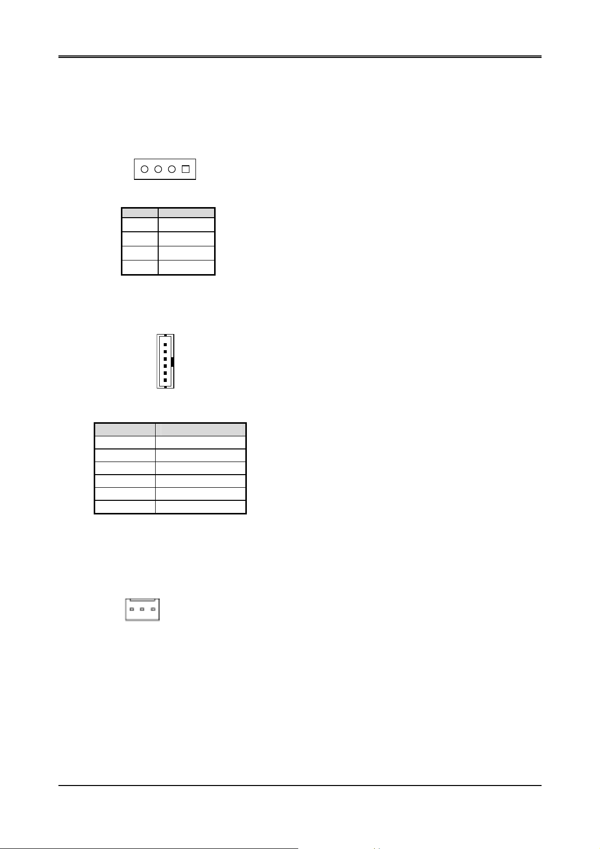
3.1 POWER ON CONNECTOR (PWR)
4 1
1 VCC(+5V)
2 GND
3 GND
4 +12V
3.2 KEYBOARD & MOUSE CONNECTOR (PS/2)
1
6
PIN SIGNAL
1 MSDATA
2 KBDATA
3 GND
4 VCC
5 MSCLOCK
6 KBCLOCK
PS/2
3.3 CPU FAN POWER CONNECTOR (FAN)
※ This is a usual FAN, can’t scout function
3 1
1. +5V
2. +12V
3. GND
8
Page 9
3.4 HARD DISK (IDE) CONNECTOR (IDE)
• 44 Pin Hard Disk Connector (IDE)
Please set as “Auto” if slave IDE device that carries FAT16 partition, is used to boot up system
2 44
AR-B1520 User’s Guide
1 43
PIN SIGNAL PIN SIGNAL
1 -RESET 2 GND
3 DATA 7 4 DATA 8
5 DATA 6 6 DATA 9
7 DATA 5 8 DATA 10
9 DATA 4 10 DATA 11
11 DATA 3 12 DATA 12
13 DATA 2 14 DATA 13
15 DATA 1 16 DATA 14
17 DATA 0 18 DATA15
19 GND 20 N.C.
21 HDDREQ 22 GND
23 -HDDIOW 24 GND
25 -HDDIOR 26 GND
27 HDDRDY 28 GND
29 -HDDACK 30 GND
31 HDDIRQ 32 N.C.
33 SA1 34 ATA 66/100
35 SA0 36 SA2
37 CS0 38 CS1
39 HDLED 40 GND
41 +5V 42 +5V
43 GND 44 N.C.
3.5 INFRARED CONNECTOR (IR)
1 5
1. VCC
2.NC
3.IR DATA REC E IVER
4.GND
5. IR DATA TRANSFER
9
Page 10

AR-B1520 User’s Guide
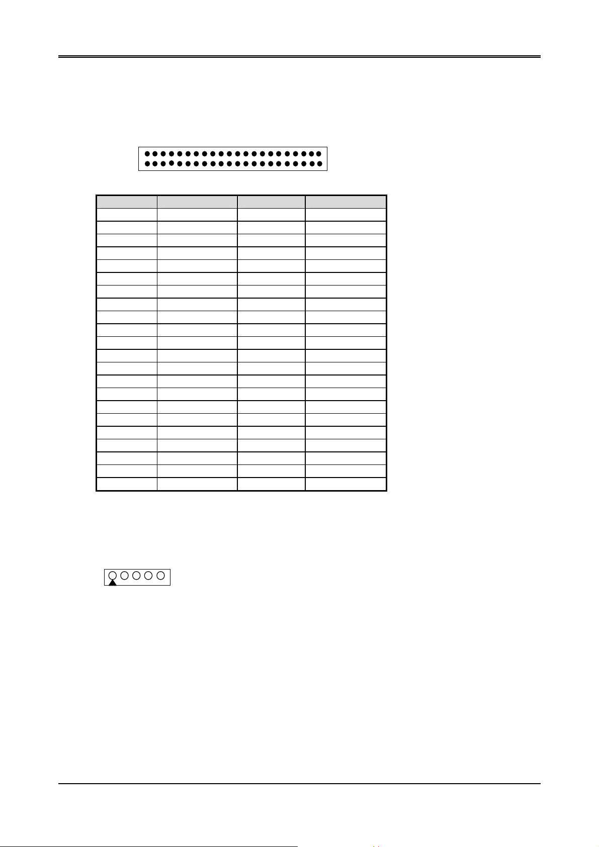
3.6 I/O CONNECTOR FOR SERIAL PORT、VGA CRT AND PARALLEL PORT (CN1)
2
68
1
PIN SIGNAL PIN SIGNAL PIN SIGNAL
1 DCDA 2 DSRA 3 RXDA
4 RTSA 5 TXDA 6 CTSA
7 DTRA 8 RIA 9 GND
10 GND 11 DCDB 12 DSRB
13 RXDB 14 RTSB 15 TXDB
16 CTSB 17 DTRB 18 RIB
19 GND 20 GND 21 -STB
22 -AFD 23 PD0 24 -ERROR
25 PD1 26 -INIT 27 PD2
28 -SLIN 29 PD3 30 PD4
31 PD5 32 PD6 33 PD7
34 -ACK 35 BUSY 36 PE
37 GND 38 SLCT 39 GND
40 GND 41 VGA RED 42 GND
43 VGA GREEN 44 GND 45 VGA BLUE
46 GND 47 HSYNCR 48 SDA
49 VSYNCR 50 SCL 51 DCDC
52 DSRC 53 RXDC 54 RTSC
55 TXDC 56 CTSC 57 DTRC
58 RIC 59 GND 60 GND
61 DCDD 62 DSRD 63 RXDD
64 RTSD 65 TXDD 66 CTSD
67 DTRD 68 RID
3.7 ETHERNET RJ-45 CONNECTOR (LAN)
34
LAN
1
7
PIN
SIGNAL
PIN
SIGNAL
1 RTX+ 5 GND
2 RTX- 6 GND
3 NRX+ 7 GND
4 NRX-
10
Page 11

3.8 USB CONNECTOR (USB)
2 10
1. VCC
3. DATA1-
AR-B1520 User’s Guide
2. VCC
4. DA TA0-
5. DATA1+
1 9
7. GND
9. GND
3.9 GPIO CONNECTOR (GPIO)
2 8 1. GPIO 0
2. GPIO 1
3. GPIO 2
1 7
4. GPIO 3
3.10 RESET CONNECTOR (RST)
1 2
3.11 CLEAR CMOS (CMOS)
1 3
CMOS
3.12 INTERAL BUZZER (LS1)
1 2
6. DA TA0+
8. GND
10. GND
5. GPIO 4
6. GPIO 5
7. GPIO 6
8. GPIO 7
PIN SIGNAL
1 RST
2 GND
PIN FUNCTION
2-3 ON
1-2 ON Clear CMOS
PIN SIGNAL
1 VCC
2 SPKR
Normal Operation
(Factory Preset)
11
Page 12

AR-B1520 User’s Guide
P2
P2
3.13 COM2 RS-232/RS-485 SELECT (P2,P3)
JUMPER FUNCTION
5 3 1
RS-485
P3
5 3 1
P3
RS-232
FACTORY PRESET
3.14 RS-485 TERMINATOR SELECT (JP2)
When there is only one line the setting should be left off, if multiple blocks are used on a single line. This should be
set to “ON” in order to properly terminate the connection for better transmission of data
1
2
Open
1
2
Closed
Factory Preset
3.15 RS-485 HEADER (JP3)
1 2 3
1 N485+
2 N4853 GND
3.16 SDRAM SOCKET 144 PIN (SODIMM)
3.17 COMPACT FLASH CONNECTOR (CF)
3.18 PC104 PLUS CONNECTOR (PCI)
The PCI connector is optional. It doesn’t mount in AR-B1520A
3.19 COMPACT FLASH CONNECTOR SELECT (JP4)
PIN FUNCTION
1 2
JP4 (ON )
1-2 ON MASTER
1-2 OFF
SLAVE
(Factory Preset)
12
Page 13

3.20 LCD CONNECTOR (LCD)
2
AR-B1520 User’s Guide
50
1
PIN SIGNAL PIN SIGNAL PIN SIGNAL
1 VVBD2 (B2) 2 LLD6 (R2) 3 VVBD3 (B3)
4 LLD7 (R3) 5 VVBD4 (B4) 6 UUD0 (R4)
7 VVBD5 (B5) 8 UUD1 (R5) 9 VVBD6 (B6)
10 UUD2 (R6) 11 VVBD7 (B7) 12 UUD3 (R7)
13 VVBD8 (G0) 14 VVBD0 (B0) 15 VVBD9 (G1)
16 VVBD1 (B1) 17 LCDVDD 18 LCDVDD
19 VVBD10 (G2) 20 UUD4 21 VVBD11 (G3)
22 UUD5 23 LLD0 (G4) 24 UUD6
25 LLD1 (G5) 26 UUD7 27 LLD2 (G6)
28 MOD 29 LLD3 (G7) 30 HSYNC
31 LLD4 32 VSYNC 33 LLD5 (R1)
34 SHFCLK 35 N.C 36 DISPOFF
37 N.C 38 N.C 39 DEN
40 GND 41 +5V 42 TVSYNC
43 +5V 44 GND 45 ENBLT
46 XCLK 47 VDDEN 48 GND
49 +12V 50 THSYNC 51 +12V
51
3.21 LCD PANEL VOLTAGE SELECT (JP1)
1
2
3
Factory Preset
1-2: 5V
2-3: 3.3V (Factory Preset)
3.22 LED MODEL CONNECTOR (LED1)
RED
GREEN
COLOR FUNCTION
RED POWER LED
GREEN LAN LED
YELLOW HDD LED
Note:
1. If the content in setting is inconsistent with the CD-ROM, please refer to the setting as the priority.
2. User may choose the collocation of ACC1520.
YELLOW
13
Page 14

AR-B1520 User’s Guide
14
Page 15

AR-B1520 User’s Guide
4. WATCHDOG TIMER
This section describes the use of Watchdog Timer. AR-B1520 is equipped with a programmable time-out period
watchdog timer that enable user to reset the system after a time out occur. Users can use simple program to enable
the watchdog timer, and program the timer in range of seconds or minutes, with maximum 255 seconds/minutes.
Once you enable the watchdog timer, the program will start the count down and when counting down to zero the
system will generate a reset signal to reset the system.
4.1 WATCHDOG TIMER SETTING
The watchdog timer is a circuit that maybe be used from your program software to detect crash or hang up.
The Watchdog timer is automatically disabled after reset. Once you enabled the watchdog timer, your program
should trigger the watchdog timer every time before it times out. After you trigger the watchdog timer, the timer will
be set to zero and start to count again. If your program f ails to trigger the watchdog t imer before times out, it will
generate a reset pulse to reset the system .
Please refer to the following table in order to properly program Watchdog function.
Users could test watchdog function under ‘Debug’ program as follows:
C:>debug
o 2e 87
o 2e 87 ;Extended Functions Enable Register
o 2e 07 ;EFIR=EFER (Extended Functions Index Register)
o 2f 08
o 2e f4 ;select CRF4 (to set Watchdog Timer Value)
o 2f 02 ;set the Watchdog timer to 2 seconds. (00 to disable, max FF)
o 2e 30 ;select device 30
o 2f 01 ;enable
q ;Quit debug
;Extended Functions Enable Register
point to Logical Device Number Reg.
;EFDR=EFIR+1 (select logical device 8, Watchdog )
15
Page 16
AR-B1520 User’s Guide
5. BIOS CONSOLE
This chapter describes the AR-B1520 BIOS menu displays and explains how to perform common tasks needed to
get up and running, and presents detailed explanatio ns of the elements found in each of t he BIOS menus. The
following topics are covered:
z Main
z Advanced
z Peripherals
z PnP/Pci
z Boot
z Exit
5.1 BIOS SETUP OVERVIEW
The BIOS is a program used to initialize and set up t he I/O system of the computer, which includes the ISA bus
and connected devices such as the video display, diskette drive, and the keyboard. The BIOS provides a
menu-based interface to the console subsystem. The console subsystem contains special software, called
firmware that interacts directly with the hardware components and facilitates interaction between the system
hardware and the operating system.
The BIOS default values ensure that the system will function at its normal capability. In the worst situation the user
may have corrupted the original settings set by the manufacturer.
After the computer is turned on, the BIOS will perform diagnostics on the system and display the size of the
memory that is being tested. Press the [Del] key to enter the BIOS Setup program, and then the main menu will
show on the screen.
The BIOS Setup main menu includes some options. Use the [Up/Down] arrow key to highlight the option that you
wish to modify, and then press the [Enter] key to select the option and configure the functions.
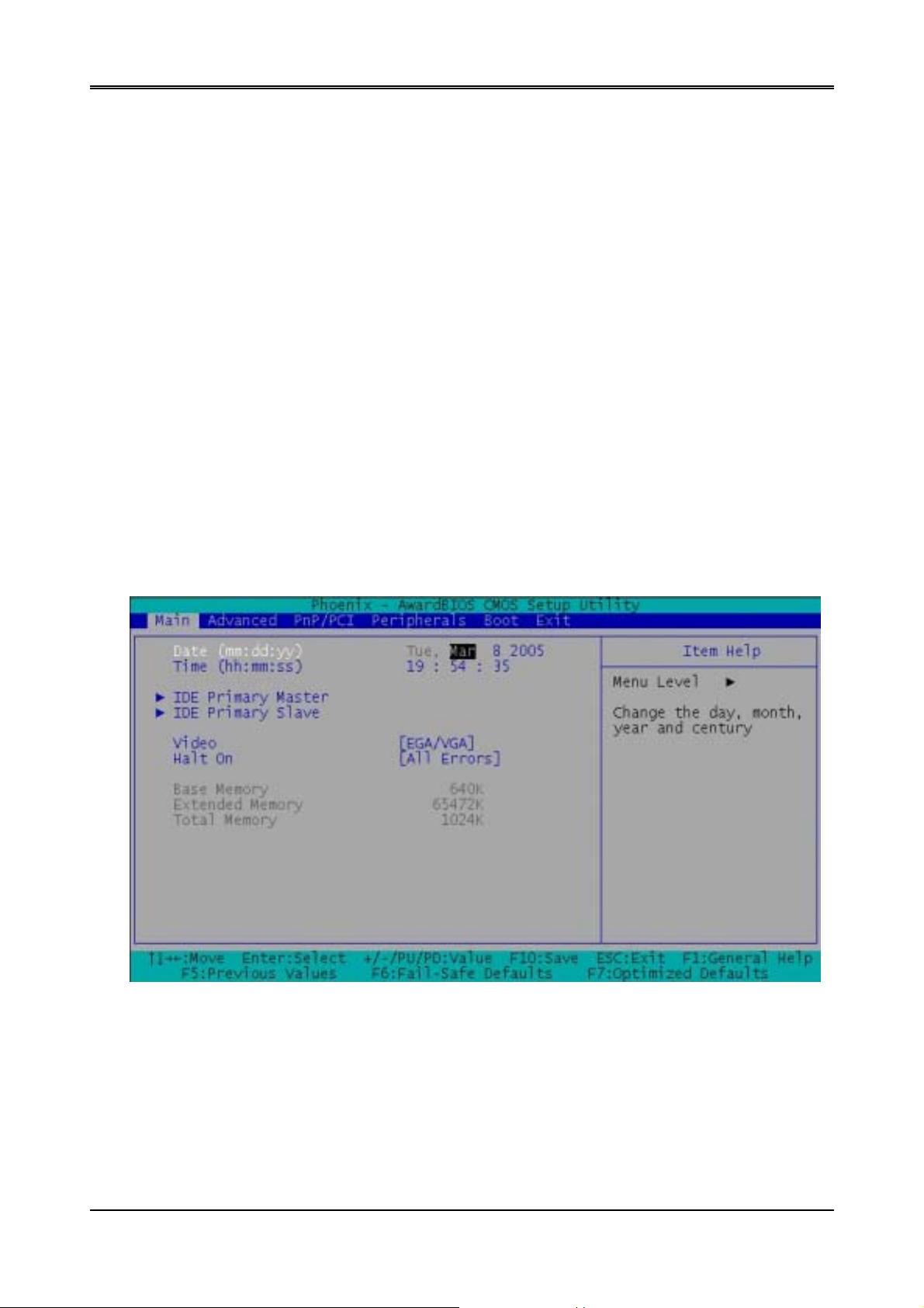
Setup Main Menu
The <Main> option allows you to record some basic system hard ware configur ation and s et the system clock and
error handling. If the CPU board is already installed in a working system, you will not need to select this opti on
anymore.
16
Page 17
AR-B1520 User’s Guide
Date & Time Setup
Highlight the <Date> field and then press the [P age Up] /[Page Down] or [+]/[-] keys to set the current date. Follow the
month, day and year format.
Highlight the <Time> field and then press the [Page Up] /[Page Down] or [+]/[-] keys to set the current date. Follow the
hour, minute and second format.
The user can bypass the date and time prompts by creating an AUTOEXEC.BAT file. For information on how to
create this file, please refer to the MS-DOS manual.
Hard Disk Setup
The BIOS supports various types for user settings, The BIOS supports <Pri Master> and <Pri Slave> so the user can
install up to two hard disks. For the master and slave jumpers, please refer to the hard disk’s installation descriptions
and the hard disk jumper settings in section three of this ma nual.
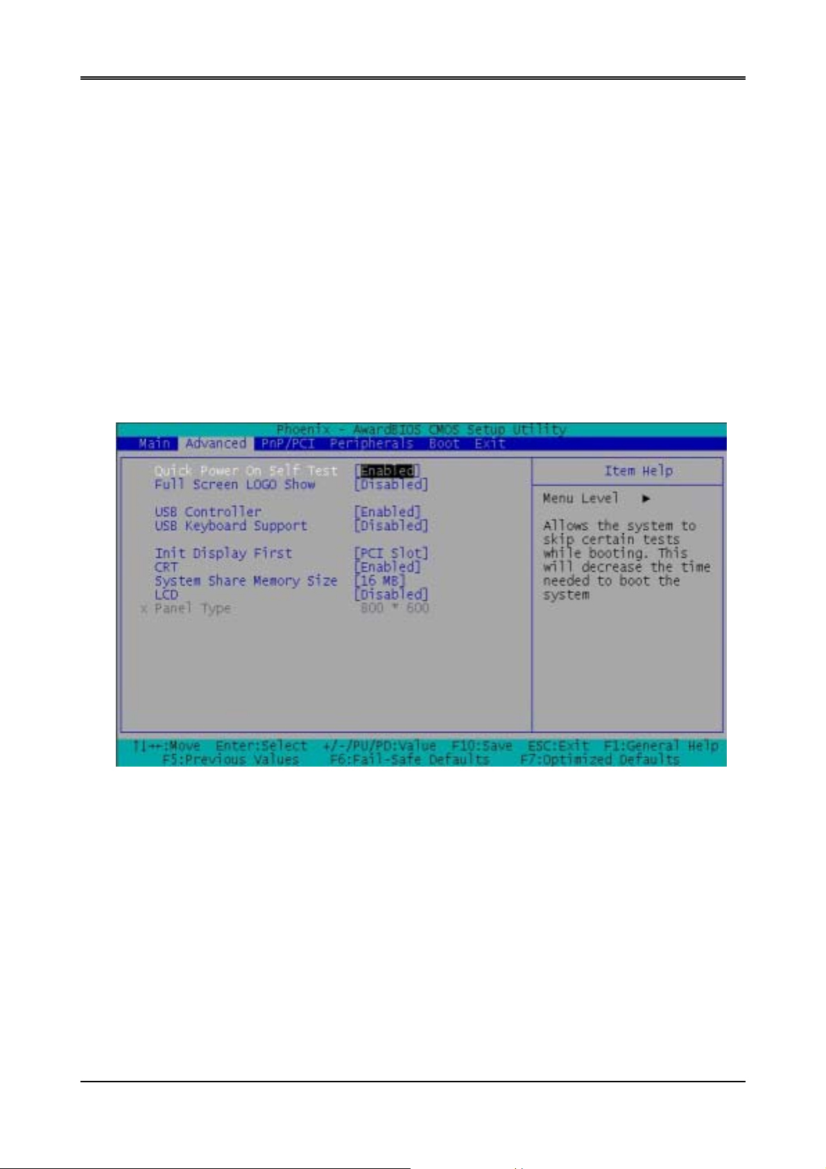
5.2 ADV ANCED SETUP
The <Advanced > option consists of configuration entries that allow you to improve your system perfor mance, or
let you set up some system features according to yo ur preference. Some entries here are required by the CPU
board’s design to remain in their default settings.
Advanced Setu
17
Page 18

AR-B1520 User’s Guide
Quick Power on Self Test
This category speeds up Power On Self Test (POST) after you power on the computer. If it is set to Enabled,
BIOS will shorten or skip some check items during POST.
USB Controller
This option can enable USB Ports or Disabled USB function.
USB Keyboard Support
This option can enable or Disabled USB keyboard function.
CRT
This option can enable VGA for CRT or Disabled CRT function.
LCD
This option can enable VGA for LCD or Disabled LCD function.
18
Page 19

AR-B1520 User’s Guide
5.3 PERIPHERALS SETUP
This option controls the configuration of the board’s chipset. Control keys for this screen are the same as for the previous
screen.
Peripherals Setup
OnBoard Serial Port 1
OnBoard Serial Port 2
OnBoard Serial Port 3
OnBoard Serial Port 4
These options enable the serial port 1,2,3,a nd 4 on the AR-B1520 .
UART Mode Select
The item allows you to determine which InfraRe d (IR) function of the onboard I/O chip, this function uses.
OnBoard Parallel Port
This option enables the parallel port on the AR-B1520.
Parallel Port Mode
This option specifies the parallel port mode. ECP and EPP are both bi-directional data transfer schemes that
adhere to the IEEE 284 specifications.
19
Page 20
AR-B1520 User’s Guide
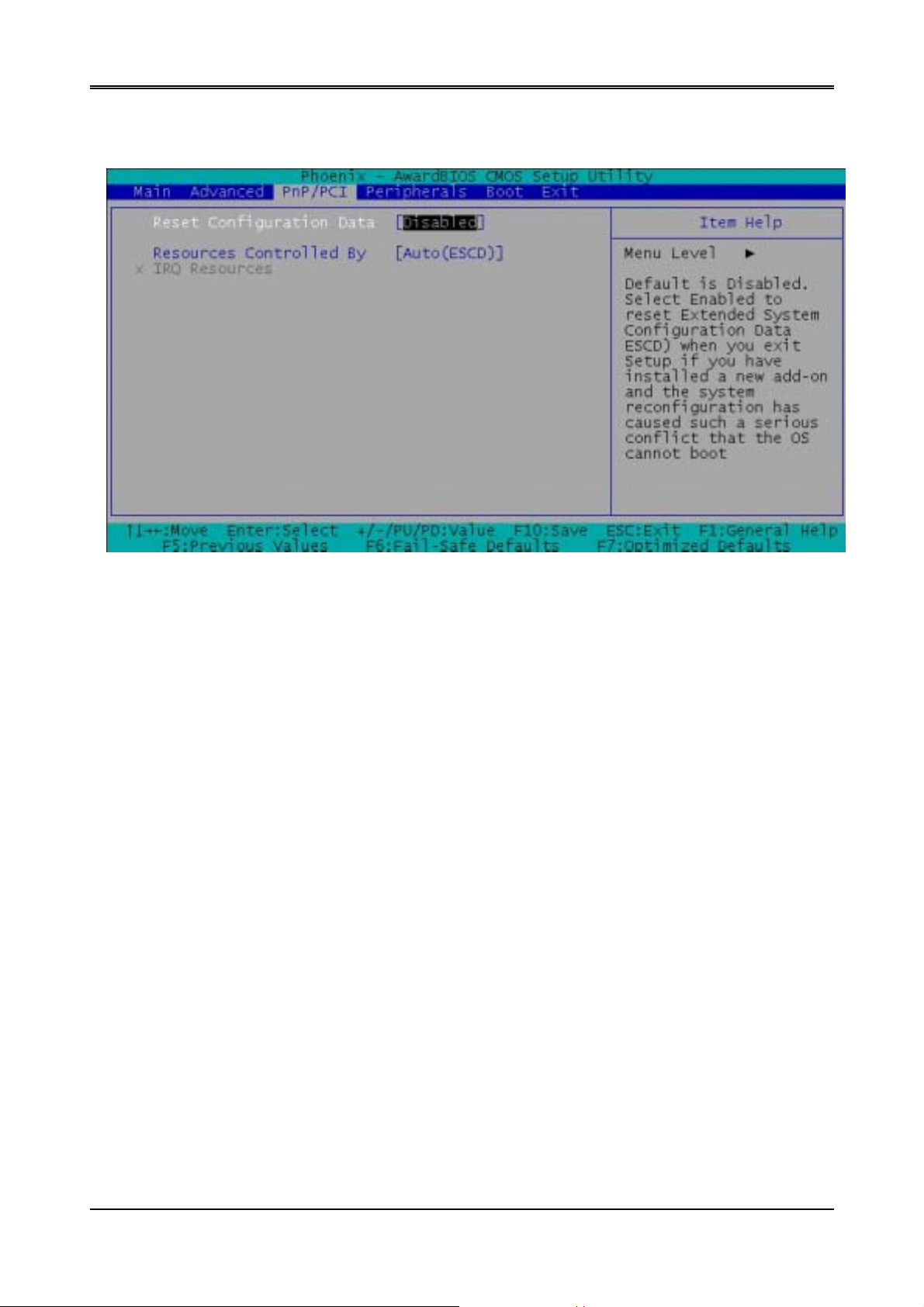
5.4 PNP/PCI SETUP
The menu allows you to select enable or disable reset e xtend system configuration data(ESCO).
PnP/PCI Setup
20
Page 21
AR-B1520 User’s Guide
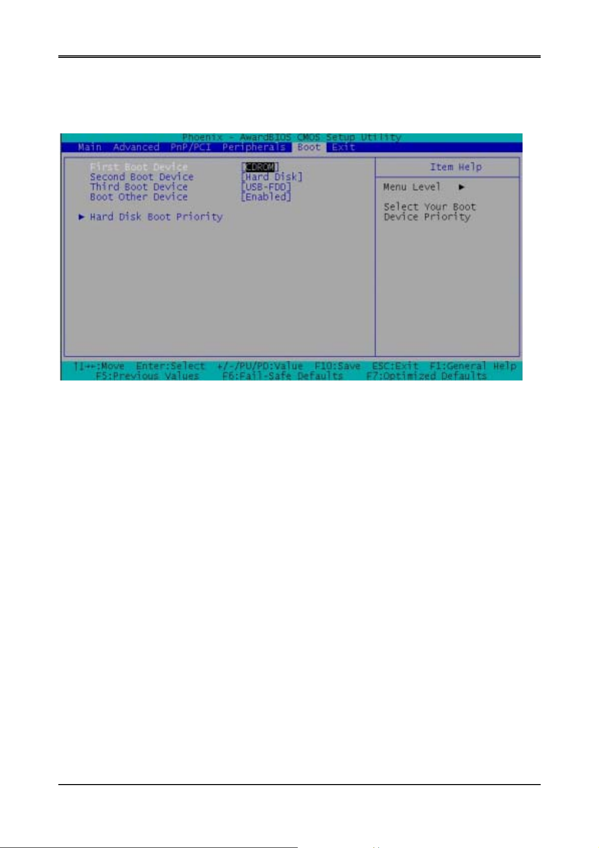
5.5 BOOT SETUP
The Boot menu allows you to select amon g the four possib le types of boo t devices listed usin g the up and do wn arrow
keys. Promotion or demotion of device alter s the priority which the s ystem uses to search for a boot device on system
power up.
First Boot Device
Second Boot Device
Third Boot Device
Boot Other Device
These options determine where the system looks first f or an operating system.
Boot Setup
21
Page 22

AR-B1520 User’s Guide
5.6 EXIT SETUP
When you have made all of your selections from the various menus in the step program, save your changes and
exit Step. Select Exit from the menu bar by to display the following menu.
NOTE:
from the legend bar to exit this menu.
Pressing <Esc> does not immediately exit this menu. Select one of the optio ns from this menu or <F 10>
Exit Setup
Save & Exit Step
Once you are finished making your selections, choose this option from the Exit menu to ensure the values you selected
are saved to the CMOS RAM. The COMS RAM is sustained by an onboard backup battery and stays on even when the
PC is turned off. When you select this option, a confirmation window appears. Select [Yes] to save changes and exit.
NOTE:If you attempt to exit the Setup program without saving your changes, the program prompts you with a
message asking if you want to save your changes before exiting. Pressing <Enter> saves the changes while
exiting.
Load Setup Defaults
This option allows you to load the default values for each of the parameters on the Setup menus. When you select this
option or if you press < F5> , a confirmation window appears. Select [Yes] to load default values. Select
Step
or make other changes before saving the values to the non-volati le RAM.
Save & Exit
Exit Without Saving
This option allows you to discard the selections you made and restore the previously saved values. After selecting this
option, a confirmation appears. Select [ Yes] t o discard any changes and exit.
22
Page 23

AR-B1520 User’s Guide
5.7 BIOS UPDATE
The BIOS program instructions are contained within computer chips called FLASH ROMs that are located on your
system board. The chips can be electronically reprogrammed, allowing you to upgrade your BIOS firmware without
removing and installing chips.
The AR-B1520 provides the FLASH BIOS update function for you to easil y to update to a newer BIOS version.
Please follow these operating steps to update to new BIOS:
Step 1: Turn on your system and don’t detect the CONFIG.SYS and AUTOEXEC.BAT files.
Step 2: Insert the FLASH BIOS diskette into the floppy disk drive.
Step 3: In the MS-DOS mode, you can type the FLASH.exe program.
A:\>AWDFLASH
Step 4: Press [ALT+F], The <File> box will show the following message, this message will be highlighted.
BIOS Filename Loading … . After typing in the File name you must press<ENTER> or press <ESC>
to exit.
Step 5: And then pleas e enter the file name to the <Enter File Name> box. And the <Message> box will
show the following notice.
Are you sure to write the BIOS into flash ROM?
Step 6: Press the <Enter> key to update the new BIOS.
Then the <Message> box will show the <Programming now …>.
Step 7: When the BIOS update is successful, the message will show <Flash ROM Update Completed -
Pass>.
23
Page 24

AR-B1520 User’s Guide
APPENDIX A. ADDRESS MAPPING
IO Address Map
I/O MAP ASSIGNMENT
0000 – 000F Direct memory access controller
0020 – 0021 Programmable interrupt controller
0040 – 0043 System timer
0060 – 0060 Standard 101/102-key or Microsoft Natural Keyboard
0061 – 0061 System speaker
0070 – 0071 System COMS/real time clock
01F0 – 01F7 SiS 5513 Dual PCI IDE Controller
Memory Map:
01F0 – 01F7
02F8 – 02FF
0378 – 037F
03F0 – 03F1 Motherboard resources
03F2 – 03F5 Standard Floppy Disk Controller
03F6 – 03F6 SiS 5513 Dual PCI IDE Controller
03F8 – 03FF
MEMORY MAP ASSIGNMENT
0000000-009FFFF System memory used by DOS and application
00A0000-00BFFFF
00C0000-00DFFFF Reserved for I/O device BIOS ROM or RAM buffer.
00E0000-00EFFFF
00F0000-00FFFFF
0100000-FFFFFFF
Primary IDE controller
Communication Port
Print Port
Communication Port
Display buffer memory for VGA/ EGA / CGA /
MONOCHROME adapter
Reserved for PCI device ROM
System BIOS ROM
System extension memory
(LPT1)
(dual fifo)
(COM2)
(COM1)
24
Page 25

APPENDIX B. INTERRUPT REQUEST (IRQ)
SETTING HARDWARE USING THE SETTING
00 System timer
01 Standard 101/102-Key or Microsoft Natural Keyboard
02 Programmable interrupt controller
03
04
06 Standard Floppy Disk Controller
07
08 System CMOS/real time clock
10 SiS 7001 PCI to USB Open Host Controller
10 IRQ Holder for PCI Steering
11 IRQ Holder for PCI Steering
12 PS/2 Compatible Mouse Port
13 Numeric data processor
14 SiS 5513 Dual PCI IDE Controller
Note:
If the content in Setting is inconsistent with CD-ROM, please refer to the Setting as priority.
Communication Port
Communication Port
Printer Port
(LPT1)
(COM2)
(COM1)
AR-B1520 User’s Guide
25
 Loading...