

Page 1

ANR-IB75N1/A/B
System Manual
1
Page 2

Copyright
All Rights Reserved.
Manual’s first edition:
For the purpose of improving reliability, design and function, the information in this
document is subject to change without prior notice and does not represent a commitment on
the part of the manufacturer.
In no event will the manufacturer be liable for direct, indirect, special, incidental, or
consequential damages arising out of the use or inability to use the product or
documentation, even if advised of the possibility of such damages.
This document contains proprietary information protected by copyright. All rights are
reserved. No part of this Manual may be reproduced by any mechanical, electronic, or other
means in any form without prior written permission of the manufacturer.
Trademarks
ANR-IB75N1 is a registered trademarks of Acrosser; IBM PC is a registered trademark
of the International Business Machines Corporation; Ivy Bridge and core TM i is a registered
trademark of Intel Technologies Inc; Award is a registered trademark of Award Software
International Inc; other product names mentioned herein are used for identification purposes
only and may be trademarks and/or registered trademarks of their respective companies.
2
Page 3

Table of Contents
Chapter 1 Introduction......................................................................... 5
1.1. ........................................................................................................ 5System Specifications
1.2. ........................................................................................................................ 8Packing List
1.3. .............................................................................................................................. 8Features
1.4. .............................................................................................................. 9System Dissection
Chapter 2 Procedures of Assembly/Disassembly............................... 12
2.1 ...................................................................................................... 122.5” HDD Installation
2.2 ......................................................................................................... 17CF Card Installation
2.3 .......................................................................................... 18Power Cord Hook Installation
2.4 ................................................................................................. 19Rack Bracket Installation
Chapter 3 Board Introduction ............................................................ 21
3.1. ........................................................................................................ 21Board Specifications
3.2. ............................................................................................................. 22Package Contents
3.3. ................................................................................................................. 23Block Diagram
Chapter 4 H/W Information............................................................... 24
4.1. ................................................................................................. 24Main board illustration
4.2. ................................................... 25Locations of IO ports & Jumper settings definition
4.3. ...................................................................................................... 26Connector pin define
4.3.1. .................................................................................. 26DDR3 DIMM Connector
4.3.2. .............................................................................................. 26SATA connector
4.3.3. ................................................................................................ 27FAN Connector
4.3.4. ........ 27LAN1~LAN8, CN_2USB1, LED1~LED3, COM1, RST1, CN3, CN4
4.3.5. .......................................................................................................... 29CF Socket
4.3.6. ................................................. 30ATX Power Connector & VGA Connector
4.3.7. .............................................................................................. 30Other Connector
Chapter 5 BIOS Settings.................................................................... 33
5.1. ....................................................................................................................... 34Main Setup
5.2. ............................................................................................................... 35Advanced Setup
5.2.1. ........................................................................................ 36SATA Configuration
5.2.2. ......................................................... 37W83627DHG Super IO Configuration
5.2.3. .................................................................. 41Serial Port Console Redirection
3
Page 4

5.2.4. .......................... 44Intel(R) 82576 Gigabit Dual Port Network Connection
5.2.5. .......................................... 45Intel(R) 82574L Gigabit Network Connection
5.3. ........................................................................................................... 46HW Monitor Setup
5.4. ................................................................................................................... 47Chipset Setup
5.4.1. .......................................................................................... 48USB Configuration
5.5. ........................................................................................................................ 49Boot Setup
5.6. .................................................................................................................. 50Security Setup
5.6.1. .......................................................................... 51HDD Password Description
5.7. ............................................................................................................ 52Save & Exit Setup
Chapter 6 Driver And Utility Installation........................................... 54
6.1. ..................................................................................... 54Driver CD Interface Introduction
6.1.1 .......................................................................................................... 55Driver Page
6.1.2 .......................................................................................................... 61Utility Page
6.1.3 .................................................................................................. 64Application Page
6.1.4 ................................................................................................... 65Documents Page
Chapter 7 Software Installation and Programming Guide................. 66
7.1. ...................................................................................................................... 66Introduction
7.1.1 ....................................................................................... 66LCD Control Module
7.1.2 .......................................................................................................... 66Watchdog
7.1.3 ................................................................................ 66LAN Bypass Subsystem
7.1.4 ...................................................... 67IB75N Library (Window platform only)
7.2. .............................................................................................................. 67File Descriptions
7.2.1 ....................................................................................... 67LCD Control Module
7.2.2 .......................................................................................................... 68Watchdog
7.2.3 ................................................................................ 68LAN Bypass Subsystem
7.3. ................................................................................................ 69API List and Descriptions
7.3.1 ............................................................................................... 69Type Definitions
7.3.2 ....................................................................................... 69LCD Control Module
7.3.3 .......................................................................................................... 71Watchdog
7.3.4 ................................................................................ 71LAN Bypass Subsystem
FAQ.................................................................................................... 73
Appendix: Technical Support Form................................................... 75
4
Page 5

Chapter 1 Introduction
ANR-IB75N1 is designed for rack-mounted platform for networking appliance, e.g. VPN, SSL,
UTM or firewall. With 3rd Generation Intel Core i7/i5/i3 Processors / Pentium CPU, It is a
powerful platform to satisfy different applications. By eight 10/100/1000Mbps LANs, the
ANR-IB75N1 is sufficient for the small to middle size business security solution.
ANR-IB75N1 can install 2 x HDD,BIOS and Jumper can control LAN bypass feature. It
provides flexibility to access Internet by user setting. For ANR-IB75N1A, it has 2 x SFP
fiber ports. For ANR-IB75N1B, it has 4 x SFP fiber ports. Customers can establish fiber
redundancy to secure their network.
1.1. System Specifications
Item Description Remark
Model Name ANR-IB75N1/A/B
Product
Descriptions
PCB AMB-IB75N1/A/B
General
Thermal solution 1. CPU FAN + System FAN
CPU 3rd Generation Inter Core i7 Processors
ANR-IB75N1/A/B Networking Rackmount Server with PCH B75, 8 *
RJ45 GbE LAN (2 pair bypass) and 0/2/4 SFP fiber GbE (w/o bypass)
i7-3770
3rd Generation Inter Core i5 Processors
i5-3550S
3rd Generation Inter Core i3 Processors
i3-3220
Intel Pentium Processor G2120
System Memory 2 x DIMM socket support DDR3
1333/1600 up to 16G
BIOS 1. Support Console re-direction
2. Support bypass setting(default disable)
3. Support boot from LAN(RJ45 L1~L8)
System Chipsets Intel PCH B75
5
Page 6

Network Interface
Ethernet 8 * RJ45 and 0/2/4 * SFP
LAN by-Pass 1. LAN1/LAN2, LAN3/LAN4 support
by-pass
2. Reserve 1*3 pin Jumper for Hardware
select bypass status
I/O
Front panel From left to right:
1. LCM module
2. Up, Down, Left, Right key pad
3. Reset Button
4. Power LED/HDD/bypass 1 & 2 :
Green/Green/Yellow/Yellow
5. 0/2/4 * SFP (F1~F4)
6. COM port (RJ45)
7. 2 * USB 3.0
8. LAN 8/7/6/5/4/3/2/1
1. LCM pin header(7-pin pinhead 2.54mm )
2. ATX 24pin Power input
Internal I/O
3. 1*8 pin 2.54mm reserve
4. VGA pin header (2*5pin, 2.0mm)
5. ATX12V 4pin Power Input
Storage
CF 1 x Compact Flash socket
Support UDMA
HDD bay 2 x 2.5” HDD bay
SATA 1 x SATA2 1 x SATA3
Others
Watchdog Timer Software programmable 1~255 Seconds,
Battery Lithium Battery, 3V 220mAH (CR2032)
Hardware
monitoring
1. CPU voltage
2. CPU and System Temperature
3. CPU FAN speed
OS support Win 7 (32/64 bit) / 7 Embedded (32 bit),
Fedora 14 (32/64 bit), Ubuntu 10 (32/64 bit)
Mechanical
Dimension 440mm*371.5mm*44mm
Operating 0~40oC (32~104oF)
6
Page 7

Temperature
Storage
-20~80oC (-4~176oF)
Temperature
Relative Humidity 0 to 90% @ 40°C, non-condensing
Power supply Standard ATX power (250W~300W)
Power
ATX circuit as AT mode with power switch
Requirements
EMC & Safety
EMC CE, FCC Class A
Safety EN 60950-1:2006/A12:2011
7
Page 8

1.2. Packing List
Check if the following items are included in the package.
Model Name Part Lists QTY
ANR-IB75N1/A/B
1.3. Features
ANR-IB75N1/A/B system
Quick manual
CD Utility
SATA cable
Console Cable(RJ45)
USA or Europe or Japan or UK power cord
Rack bracket
Screw for bracket (for Rack + HDD bracket)
Power cord hook
Box Packing
1
1
1
2
1
1
2
1
1
1
Supports LGA1155 Intel® Core™ i7/i5/i3 processor / Pentium CPU
Intel B75 Chipset
DDRIII DIMM x 2, up to 16GB memory
Intel 82574L 10/100/1000Mbps x 8
Two pairs LAN ports support bypass feature (LAN 1/2 + LAN 3/4)
LAN bypass can be controlled by BIOS and Jumper
CF socket, 2.5” HDD x 2, SATA II interface x 1, SATA III interface x 1
Console, VGA (pinhead), USB 3.0 x 2 (connectors)
Support boot from LAN, console redirection
8
Page 9

1.4. System Dissection
(1) Dimensions
(2) Front Panel (ANR-IB75N1B)
LCM Module
Fiber SFP *2
Keypad LEDs
Fiber SFP *2
Console
USB*2 LEDs
9
LAN *8
Page 10

3
9
5
6
7
8
(3) Back Panel
(4) System Configuration
1
Power Inlet
2
4
10
10
Page 11

Item Description Quantity
1 TOP COVER 1
2 POWER SUPPLY 1
3 BOTTOM BASE 1
4 POWER BRACKET 1
5 1U EAR BRACKET 2
6 HDD BRACKET 1
7 MEMBRANE 1
8 AMB-IB75N1/A/B 1
9 CPU Heatsink module 1
10 FAN 3
11
Page 12

Chapter 2 Procedures of Assembly/Disassembly
2.1 2.5” HDD Installation
The following instructions will guide you to install 2.5” HDD step-by-step.
1. Unfasten 2 screws of chassis top cover and take off it.
2. Release HDD bracket by unfastening 4 screws.
12
Page 13

3. Take out HDD screws from packing bag.
4. Fix HDD with HDD bracket by 4 screws.
13
Page 14

5. Fix HDD with HDD bracket by 4 screws.
14
Page 15

6. Plug SATA power cable into motherboard.
7. The SATA power cable MUST go through below M/B power cable, please follow
below photo.
15
Page 16

8. Connect SATA cable and SATA power cable with HDD module.
9. Assemble top cover back by fastening the 2 screws.
16
Page 17

2.2 CF Card Installation
1. Open the top cover (the same as above steps).
2. Push CF card into CF socket.
3. Finish the CF card installation.
17
Page 18

2.3 Power Cord Hook Installation
1. Take out the hook from packing bag.
2. Install the hook from right side firstly.
3. Then install the hook by left side.
18
Page 19

2.4 Rack Bracket Installation
1. Take out the screws and Rack bracket from packing bag.
2. Fixed the Rack bracket to Chassis by fastening 6 screws.
19
Page 20

Board Guide
20
Page 21

Chapter 3 Board Introduction
AMB-IB75N1 is designed for rack-mounted platform for networking appliance, e.g. VPN, SSL,
UTM or firewall. With 3rd Generation Intel Core i7/i5/i3 Processors / Pentium CPU, It is a
powerful platform to satisfy different applications. By eight 10/100/1000Mbps LANs, the
AMB-IB75N1 is sufficient for the small to middle size business security solution.
AMB-IB75N1 can install 2 x HDD,BIOS, and Jumper can control LAN bypass feature. It
provides flexibility to access Internet by user setting. For AMB-IB75N1A, it has 2 x SFP
fiber ports. For AMB-IB75N1B, it has 4 x SFP fiber ports. Customers can establish fiber
redundancy to secure their network.
3.1. Board Specifications
Supports LGA1155 Intel® Core™ i7/i5/i3 processor / Pentium CPU
Intel B75 Platform
SATAII x 1, SATAIII x1
USB3.0 x2
Option1: Intel GbE LAN x8
Option1: Intel GbE LAN x8 + 2 Fiber
Option1: Intel GbE LAN x8 + 4 Fiber
21
Page 22

3.2. Package Contents
Check if the following items are included in the package.
Model Name Part Lists QTY
AMB-IB75N1/A/B
AMB-IB75N1/A/B Board
Quick manual 1
SATA cable 2
CD Utility 1
Console Cable (RJ45) 1
Box Packing 1
1
22
Page 23

3.3. Block Diagram
23
Page 24
Chapter 4 H/W Information
This chapter describes the installation of AMB-IB75N1/A/B. At first, it shows the
Function diagram and the layout of AMB-IB75N1/A/B. It then describes the unpacking
information which you should read carefully, as well as the jumper/switch settings for the
AMB-IB75N1/A/B configuration.
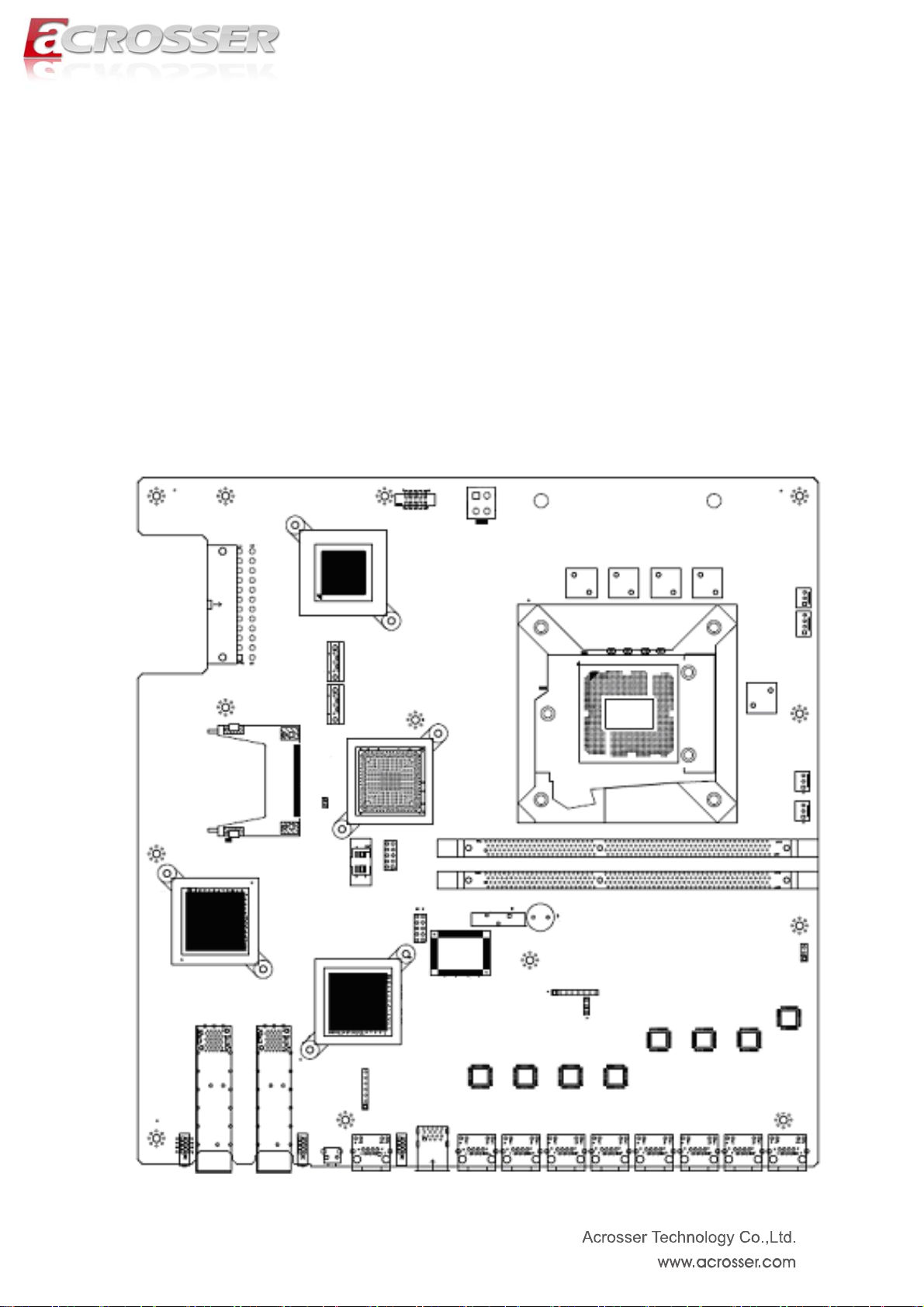
4.1. Main board illustration
24
Page 25

9 876
54 3
7
5
3
9
825
3
30292827 35 36
4.2. Locations of IO ports & Jumper settings definition
26
33
4
24 23
22
21 20
1
1
1
161
14
12
1
11 10
1
2
31
32
25
Page 26
4.3. Connector pin define
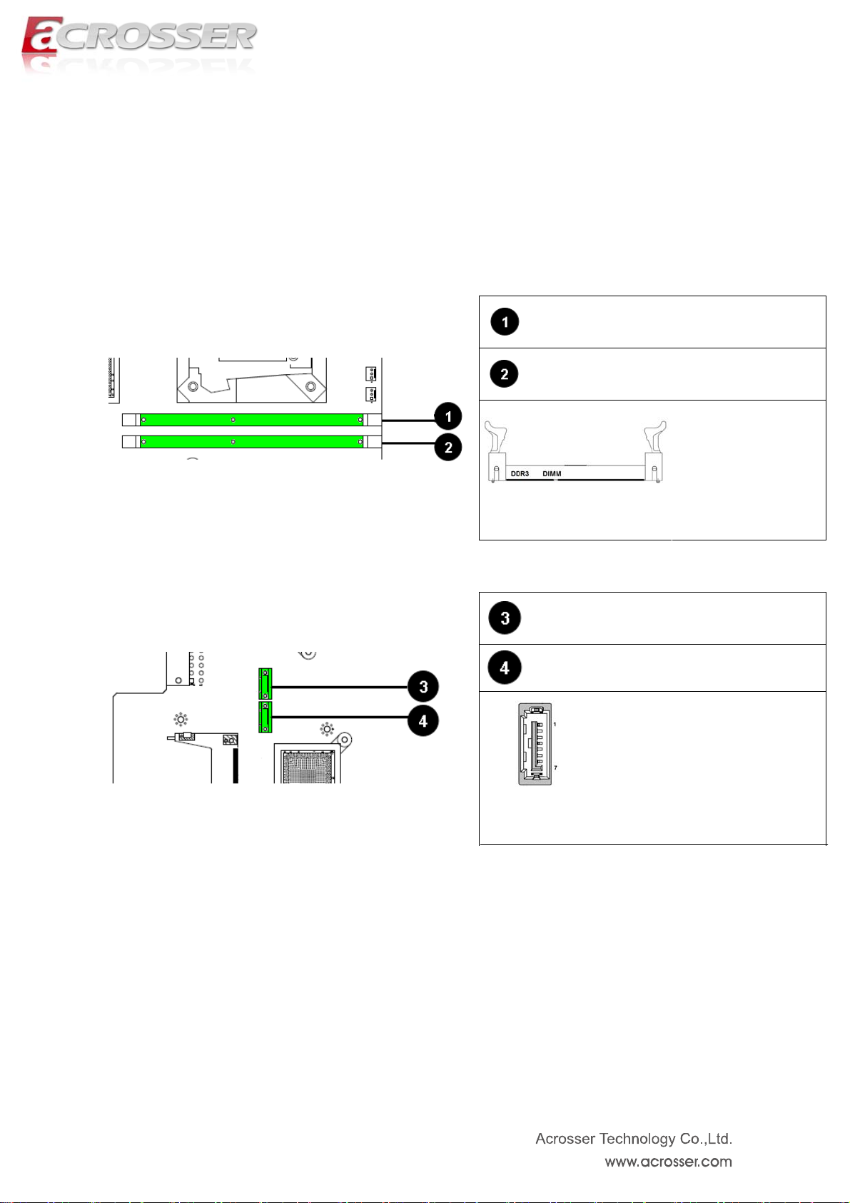
4.3.1. DDR3 DIMM Connector
DIMM1
DIMM2
Standard
DDR3 DIMM
connector
4.3.2. SATA connector
SATA1 (SATA III)
SATA2 (SATA II)
Standard SATA connector
26
Page 27

4.3.3. FAN Connector
SYSFAN3
SYSFAN2
SYSFAN1
PIN Signal
1 GND
2 +12V
FAN Speed
3
3 Pin, Pitch:2.54mm
Detect
CPUFAN1
PIN Signal
1 GND
2 +12V
FAN Speed
3
4
4 Pin, Pitch:2.54mm
Detect
FAN PWM
Control
4.3.4. LAN1~LAN8, CN_2USB1, LED1~LED3, COM1, RST1, CN3, CN4
27
Page 28
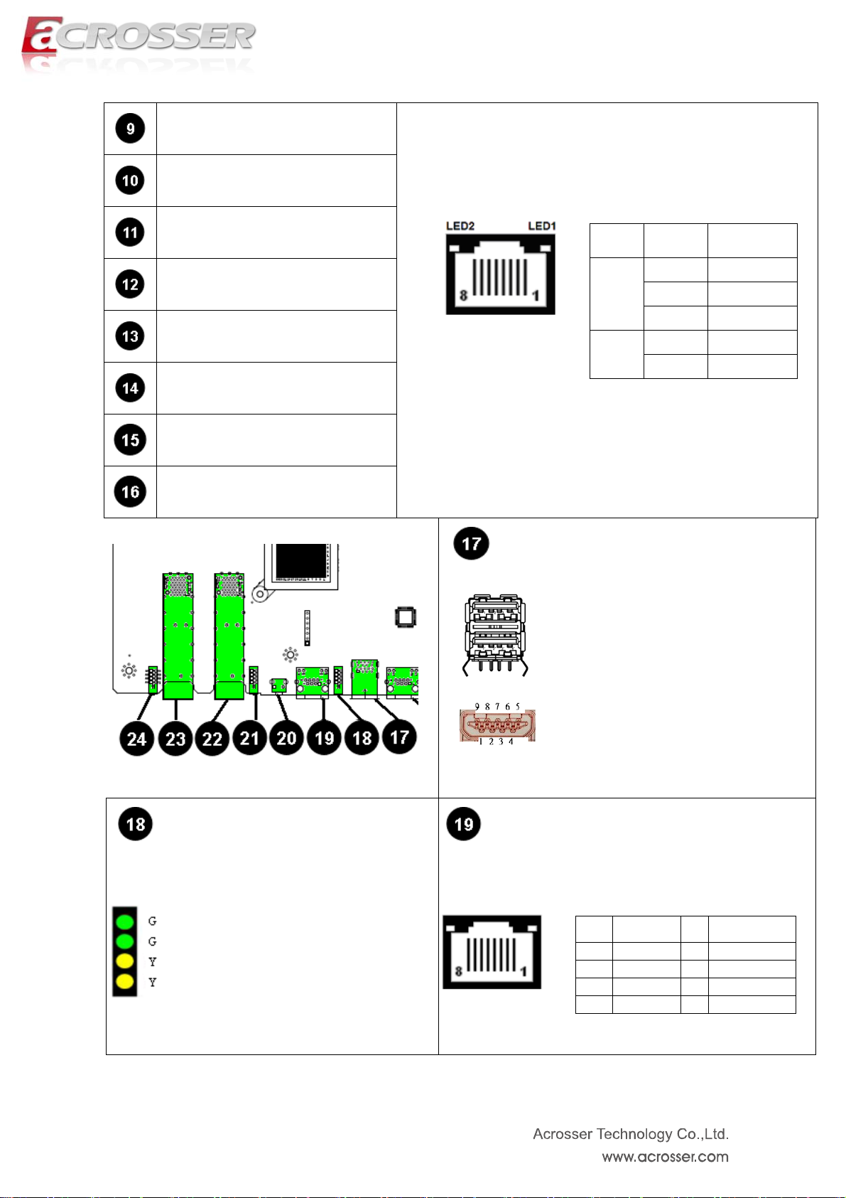
LAN1 RJ45 LAN Connector
LAN2 RJ45 LAN Connector
LAN3 RJ45 LAN Connector
LAN4 RJ45 LAN Connector
LAN5 RJ45 LAN Connector
LAN6 RJ45 LAN Connector
LAN7 RJ45 LAN Connector
LAN8 RJ45 LAN Connector
LAN LED table:
LED ON/OFF Status
OFF 10Mbps
LED1
LED2
Green 100Mbps
Orange 1000Mbps
Yellow Link/Active
OFF LAN OFF
CN_2USB1
LED3 COM1
Green1: Power ON LED.
Green2: HDD LED
Yellow1: LAN3&LAN4 Bypass
LED.
Yellow2: LAN1&LAN2 Bypass
LED.
Standard USB 3.0 Type-A connector
RS-232, RJ45 connector
PIN Signal PIN Signal
1 RTS 5 GND
2 DTR 6 SIN
3 SOUT 7 DSR
4 GND 8 CTS
28
Page 29
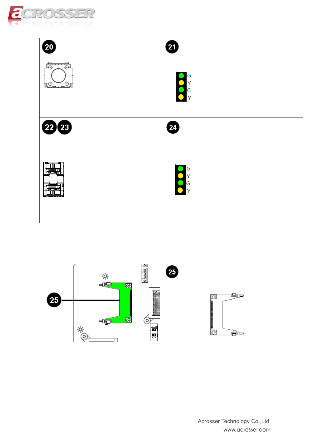
RST1 LED2
UP :
Green1: Link LED
Push this button to reset the
system.
CN3, CN4 LED1
Dual SFP Connector.
1000BASE-SX/LX SMALL
FORM-FACTOR
PLUGGABLE (SFP) OPTICAL FIBER
TRANSCEIVER OR MINI-GBIC
CONNECTOR
Yellow1: Active LED
Down :
Green2: Link LED
Yellow2: Active LED
UP :
Green1: Link LED
Yellow1: Active LED
Down :
Green2: Link LED
Yellow2: Active LED
4.3.5. CF Socket
CF1
CF CARD Socket
29
Page 30
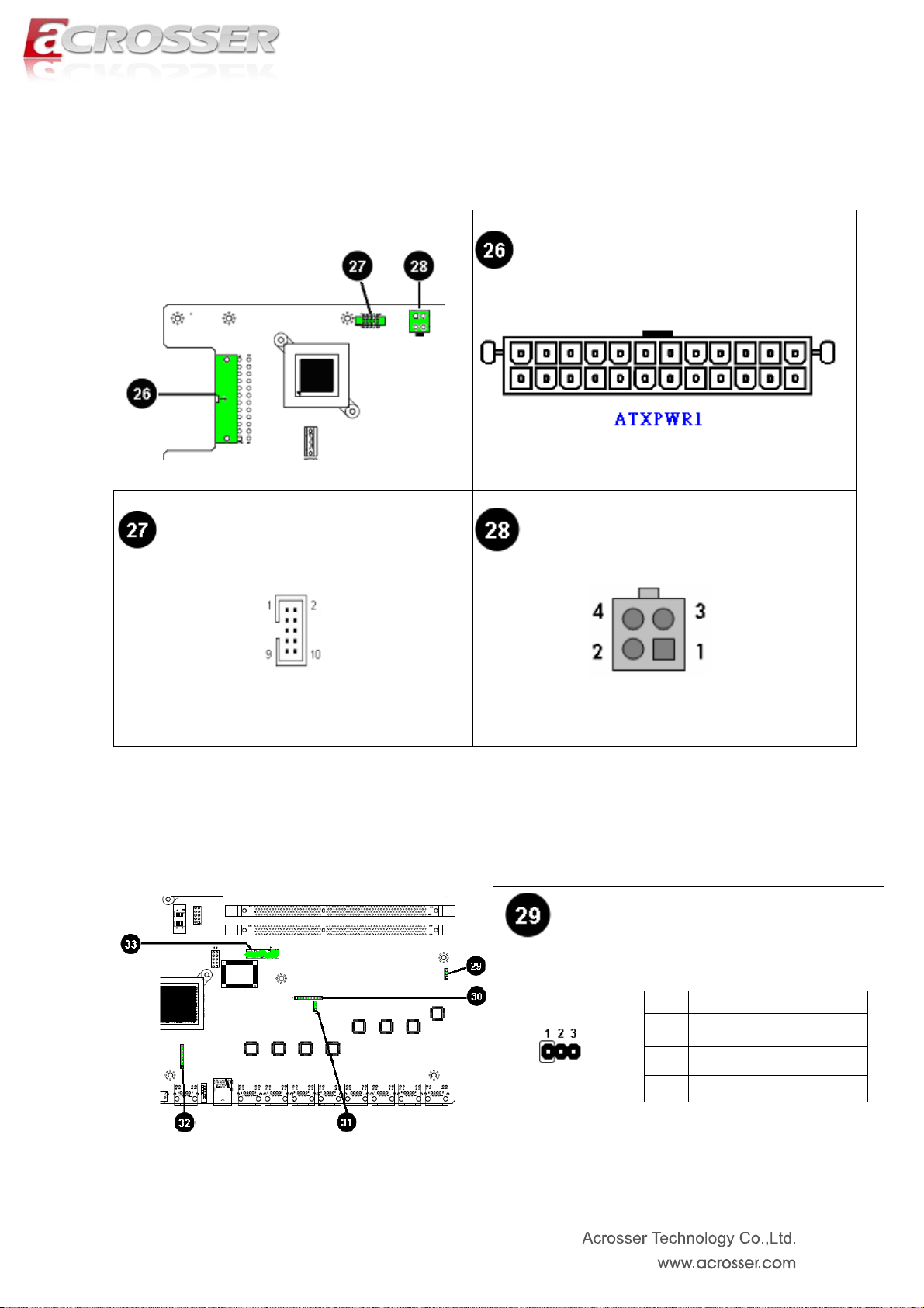
4.3.6. ATX Power Connector & VGA Connector
ATXPWR1 ATX Power Supply Input
FP_VGA1 VGA Wafer Connector
4.3.7. Other Connector
ATX12V1 ATX12V Power Input
JP2
(For LAN1/LAN2 Bypass
Function Select.).
PIN Function
1-2 Forced Normal (Default)
30
2-3 Controlled By CPLD
Open Forced Bypass
Page 31

JP4
(For LAN3/LAN4 Bypass Function
Select.).
PIN Function
1-2 Forced Normal (Default)
2-3 Controlled By CPLD
Ope
Forced Bypass
n
CPLD1
LCM1
For CPLD Firmware Update
PIN Signal PIN Signal
1 3VDUAL 2 G_TDO
3 G_TDI 4 NC
5 NC 6 G_TMS
7 GND 8 G_TCK
LCM signal connector
PIN Signal PIN Signal
1 3VDUAL 2 G_TDO
3 G_TDI 4 NC
5 NC 6 G_TMS
7 GND 8 G_TCK
RTC1
An onboard battery saves the CMOS
memory to keep the BIOS information
stays on even after disconnected
your system with power source. Nevertheless,
this backup battery exhausts after
some five years.
CMOS Backup Battery:
LPC1 LPC Header For Port’80 Debug
PIN Signal PIN Signal
1 33MHz 2 LAD1
3 Reset 4 LAD0
5 FRAME# 6 VCC3
SPI1
7 LAD3 8 GND
9 LAD2 10 GND
SPI BIOS firmware Update
Header
PIN Signal PIN Signal
1 CS0 2 VCC3
3 MISO 4 HOLD#
5 WP# 6 SPICLK
7 GND 8 MOSI
9 NC 10 NC
31
Page 32

CCMOS1 CMOS Memory Clearing Header
Extended Models Information
Model Name Model Parts Difference Remark
AMB-IB75N1 Intel GbE LAN x8
AMB-IB75N1A Intel GbE LAN x8 + 2 Fiber
CN3
AMB-IB75N1B Intel GbE LAN x8 + 4 Fiber
CN3 CN4
32
Page 33

Chapter 5 BIOS Settings
This chapter describes the BIOS menu displays and explains how to perform common
tasks needed to get the system up and running. It also gives detailed explanation of the
elements found in each of the BIOS menus. The following topics are covered:
Main Setup
Advanced Setup
HW Monitor
Chipset Setup
Boot Setup
Security Setup
Save Exit Setup
33
Page 34

5.1. Main Setup
Once you enter the AMI BOS™ CMOS Setup Utility, the Main Menu will appear on the
screen. Use the arrow keys to highlight the item and then use the <+> <-> keys to select the
value you want in each item.
Note: Listed at the bottom of the menu are the control keys. If you need any help with the
item fields, you can press the <F1> key, and it will display the relevant information.
34
Page 35

5.2. Advanced Setup
Option Choice Description
SA TA Configuration
W83627DHG Super
IO Configuration
Serial Port Console
Redirection
Intel(R) 82576
Gigabit Dual Port
Network Connection
Intel(R) 82574L
Gigabit Network
Connection
N/A SATA Device Options Settings
N/A System Super IO Chip Parameters.
N/A Serial Port Console Redirection
N/A Configure Gigabit Ethernet device parameters
N/A Configure Gigabit Ethernet device parameters
35
Page 36

5.2.1. SATA Configuration
SA TA Mode
Option Choice Description
Selection
Port 1
Port 2
CF card
IDE / AHCI Determines how SATA controlle r(s) operate.
Disabled / Enabled Enable or Disable SAT A Port
Disabled / Enabled Enable or Disable SAT A Port
Disabled / Enabled Enable or Disable SAT A Port
36
Page 37

5.2.2. W83627DHG Super IO Configuration
Option Choice Description
COM1 Configuration
COM2 Configuration
LAN by Pass
Function
N/A Set Parameters of Serial Port 1 (COMA)
N/A Set Parameters of Serial Port 2 (COMB)
Disabled / Enabled Enable or Disable Lan by pass function
37
Page 38
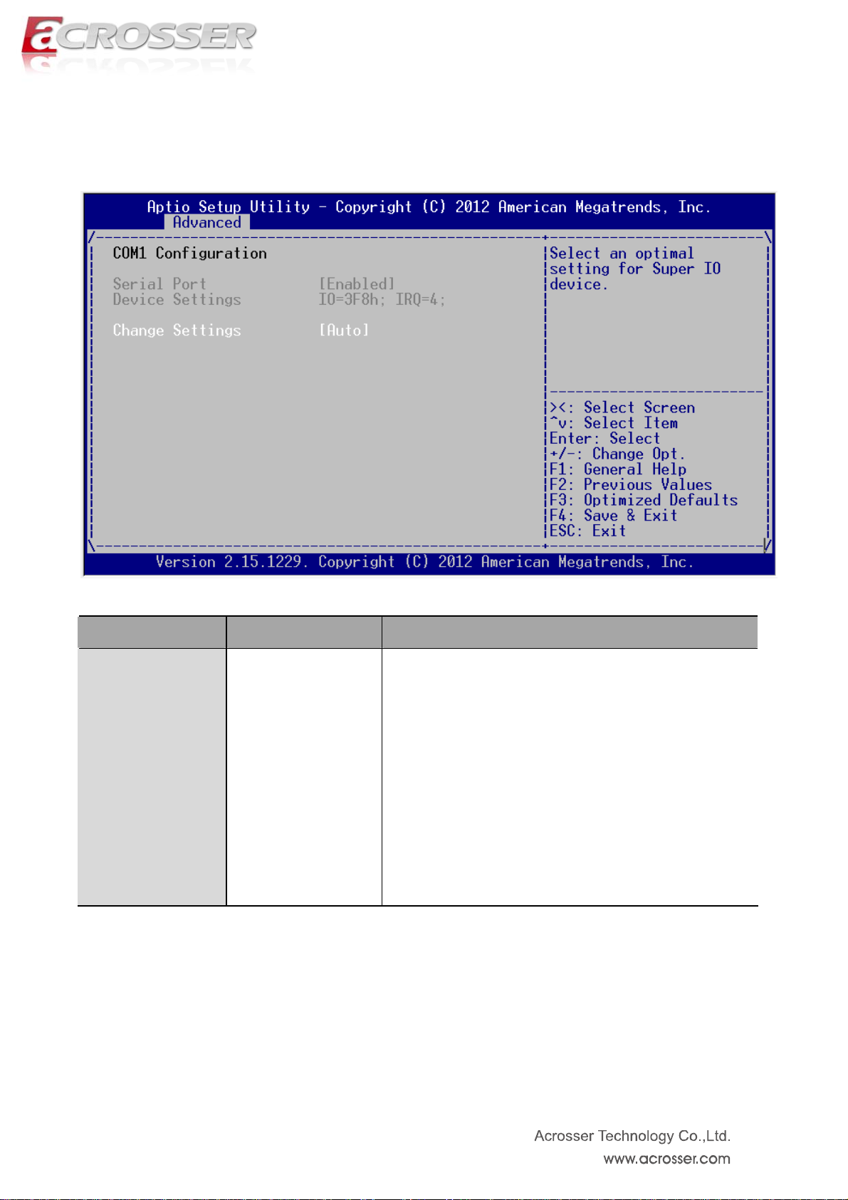
5.2.2.1. COM1 Configuration
Option Choice Description
Change Settings
Auto IO=3F8h; IRQ=4
/ IO=3F8h;
IRQ=3,4,5,6,7,10,11,1
2 / IO=2F8h;
IRQ=3,4,5,6,7,10,11,1
Select an optimal setting for Super IO device.
2 / IO=3E8h;
IRQ=3,4,5,6,7,10,11,1
2 / IO=2E8h;
IRQ=3,4,5,6,7,10,11,1
2
38
Page 39

5.2.2.2. COM2 Configuration
39
Page 40

Option Choice Description
Serial Port
Change Settings
Disabled / Enabled Enable or Disable Serial Port (COM)
Auto IO=3F8h; IRQ=4
/ IO=3F8h;
IRQ=3,4,5,6,7,10,11,1
2 / IO=2F8h;
IRQ=3,4,5,6,7,10,11,1
Select an optimal setting for Super IO device.
2 / IO=3E8h;
IRQ=3,4,5,6,7,10,11,1
2 / IO=2E8h;
IRQ=3,4,5,6,7,10,11,1
2
Standard Serial Port
Mode / IrDA Active
pulse 1.6 Us / IrDA
Active pulse 3/16 bit
time / ASK-IR Inverting
Device Mode
IRTX, Routed to IRRX
/ ASK-IR Inverting
Change the Serial Port mode. Select <High S peed> or
IRTX &500KHz,
<Normal mode> mode
Routed to IRRX /
ASK-IR Inverting
IRTX, Demodulation to
IRRX / ASK-IR
Inverting
IRTX&500KHz,
Demodulation to IRRX
40
Page 41

5.2.3. Serial Port Console Redirection
Option Choice Description
Console Redirection
Console Redirection
Settings
EMS
EMS Settings
Disabled / Enabled Console Redirection Enable or Disable.
The settings specify how the host computer and the remote
N/A
Disabled / Enabled windows emergency management service
N/A
computer (which the user is using) will exchange data. Both
computers should have the same or compatible settings.
The settings specify how the host computer and the remote
computer (which the user is using) will exchange data. Both
computers should have the same or compatible settings.
41
Page 42
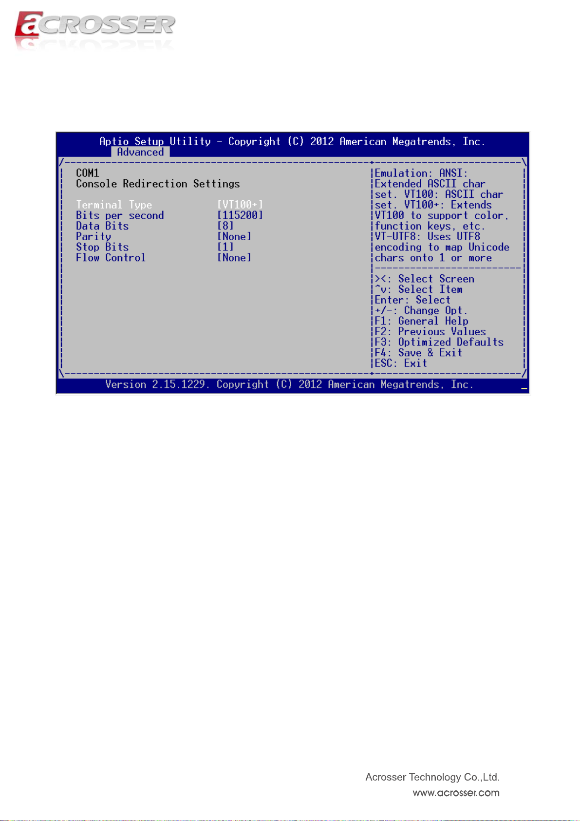
5.2.3.1. Console Redirection Settings
42
Page 43

Option Choice Description
Emulation: ANSI: Extended ASCII char set. VT100: ASCII
Terminal Type
Bits per second
Data Bits
Parity
Stop Bits
Flow Control
VT100 / VT100+ /
VT-UTF8 / ANSI
9600 / 19200 /
38400 / 57600 /
115200
7 / 8 Data Bits
None / Even / Odd /
Mark / Space
1 / 2
None / Hardware
RTS/CTS
char set. VT100+: Extends VT100 to support color , function
keys, etc. VT-UTF8: Uses UTF8 encoding to map Unicode
chars onto 1 or more
Selects serial port transmission speed. The speed must be
matched on the other side. Long or noisy lines may require
lower speeds.
A p arity bit ca n be sent with the data bits to detect some
transmission errors. Even: parity bit is 0 if the num of 1's in
the data bits is even. Odd: parity bit is 0 if num of 1's in the
data
Stop bits indicate the end of a serial data packet. (A start bit
indicates the standard setting is 1 stop bit. Communication
with slow devices may require more than 1
Flow control can prevent data loss from buffer overflow.
When sending data, if the receiving buffers are full, a 'stop'
signal can be sent to stop the data flow.
43
Page 44

5.2.4. Intel(R) 82576 Gigabit Dual Port Network Connection
Option Choice Description
NIC Configuration
Blink LEDs (range
0-1
Link Status
N/A Click to configure the network device port.
N/A Blink LEDs for the specified duration (up to 15 seconds).
Disconnected Link Status
44
Page 45
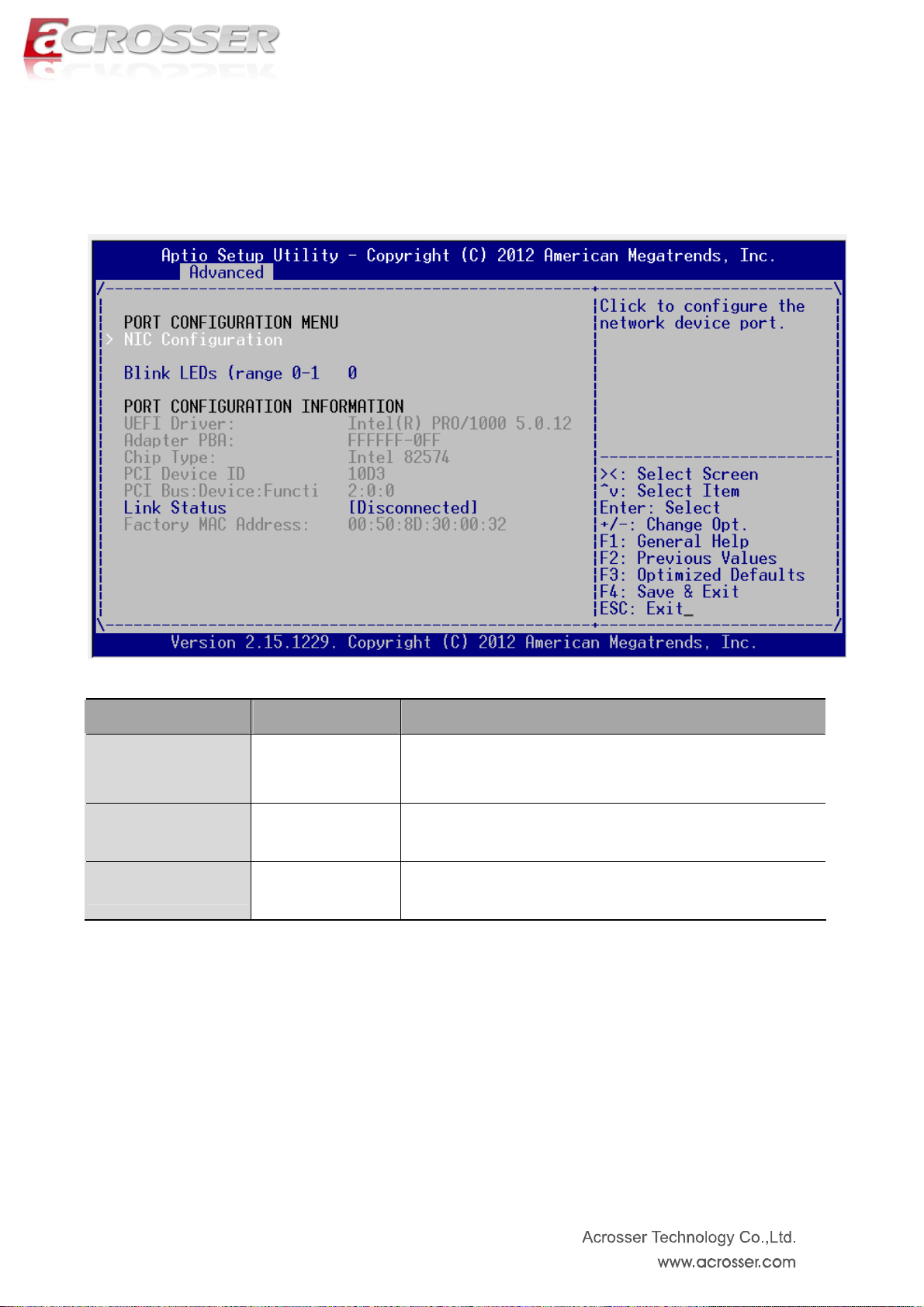
5.2.5. Intel(R) 82574L Gigabit Network Connection
Option Choice Description
NIC Configuration
Blink LEDs (range
0-1
Link Status
N/A Click to configure the network device port.
N/A Blink LEDs for the specified duration (up to 15 seconds).
Disconnected Link Status
45
Page 46
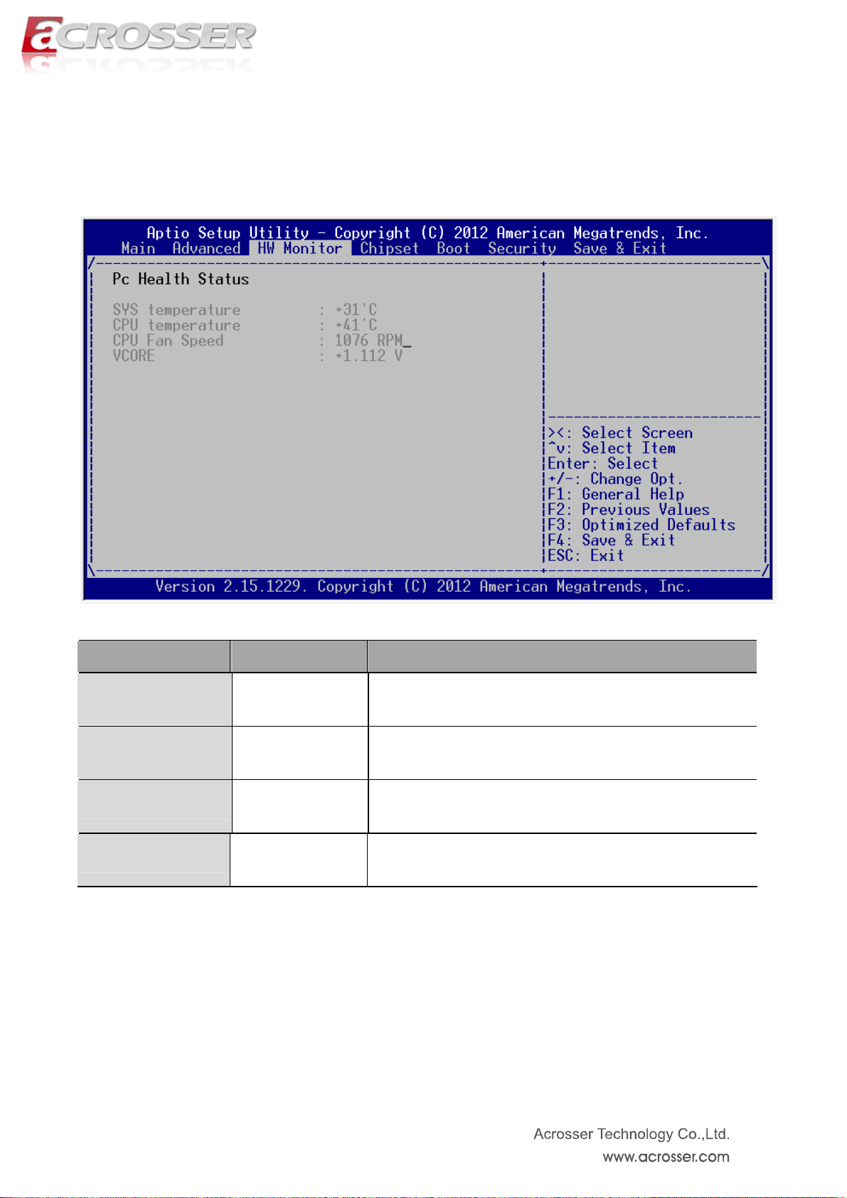
5.3. HW Monitor Setup
Option Choice Description
SYS temperature
CPU temperature
CPU Fan Speed
VCORE
N/A This item displays the System Temperature
N/A This item displays the CPU Temperature
N/A This item displays the CPU FAN Speed
N/A This item displays the VCORE
46
Page 47
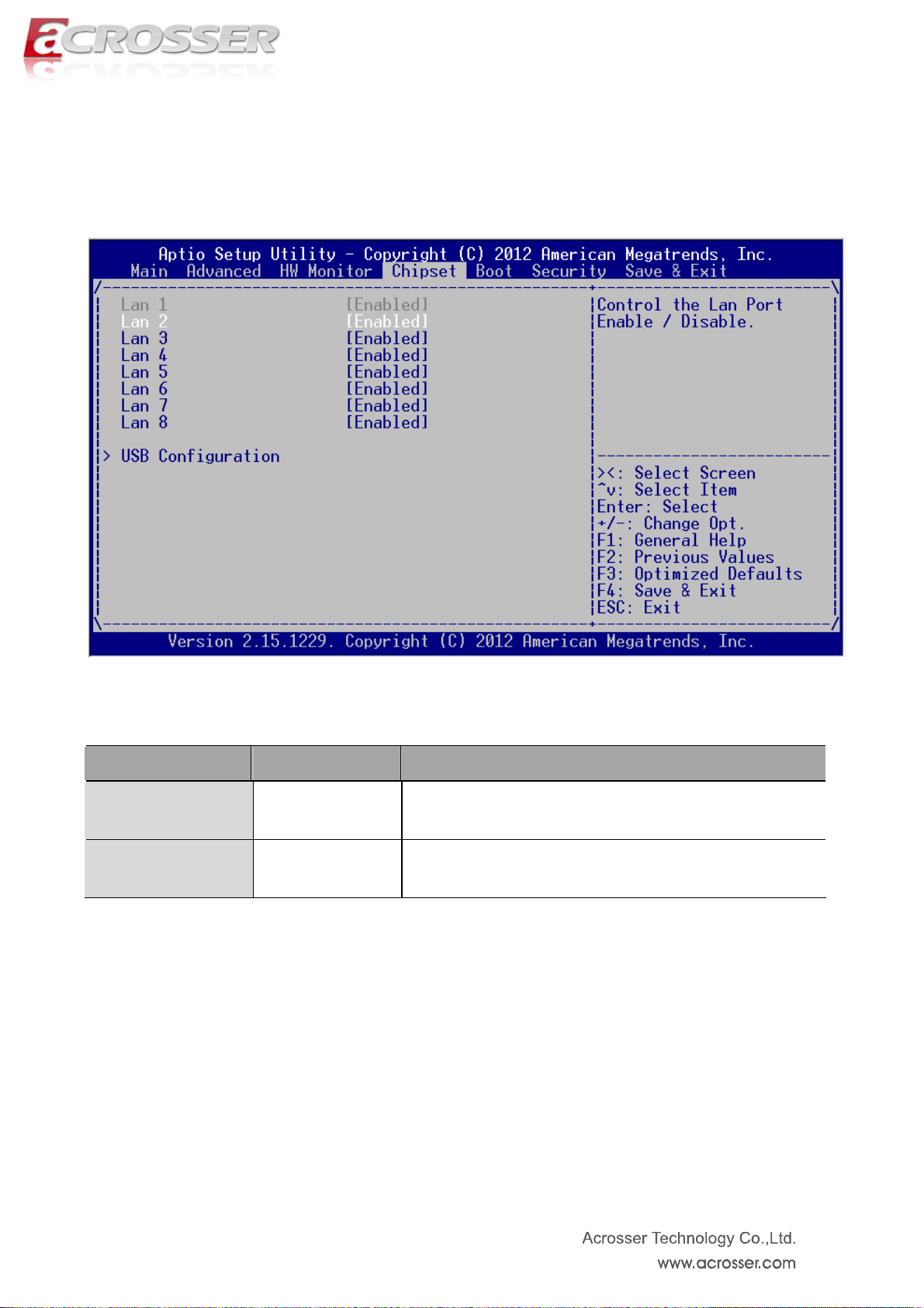
5.4. Chipset Setup
Option Choice Description
LAN1 ~ 8
USB Configuration
Disabled / Enabled Control the LAN Port Enable / Disable
N/A USB Configuration settings
47
Page 48

5.4.1. USB Configuration
Option Choice Description
xHCI Mode
EHCI1
Smart Auto / Auto /
Disabled / Enabled
Disabled / Enabled
Mode of operation of xHCI controller.
Control the USB EHCI (USB 2.0) functions. One EHCI
controller must always be enabled.
48
Page 49
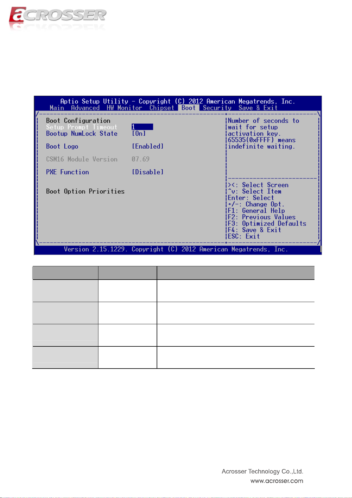
5.5. Boot Setup
Option Choice Description
Setup Prompt
Timeout
Boot up NumLock
State
Boot Logo
PXE Function
Number of seconds to wait for setup activation key.
N/A
65535(0xFFFF) means indefinite waiting.
ON / OFF Select the keyboard NumLock state
Disabled / Enabled Enables or disables Quiet Boot option
Disabled / Enabled Controls the execution of UEFI and Legacy PXE OpROM
49
Page 50

5.6. Security Setup
option Choice Description
dministrator
Password
HDD module name
N/A Set Administrator Password
Set HDD Password (It will show the HDD model, if you have
N/A
to join the HDD.)
50
Page 51
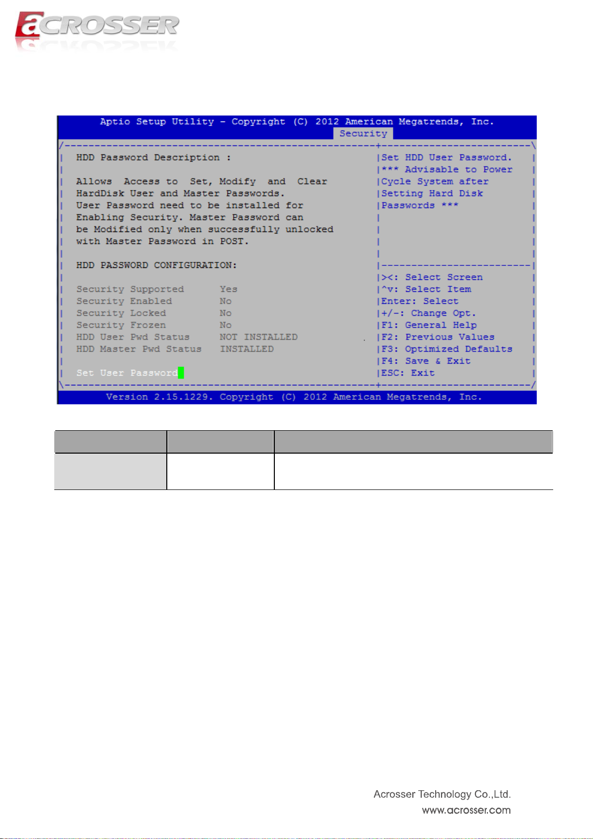
5.6.1. HDD Password Description
option Choice Description
Set HDD Password
Set HDD User Password.*** Advisable to Power Cycle
N/A
System after setting Hard Disk Passwords ***
51
Page 52
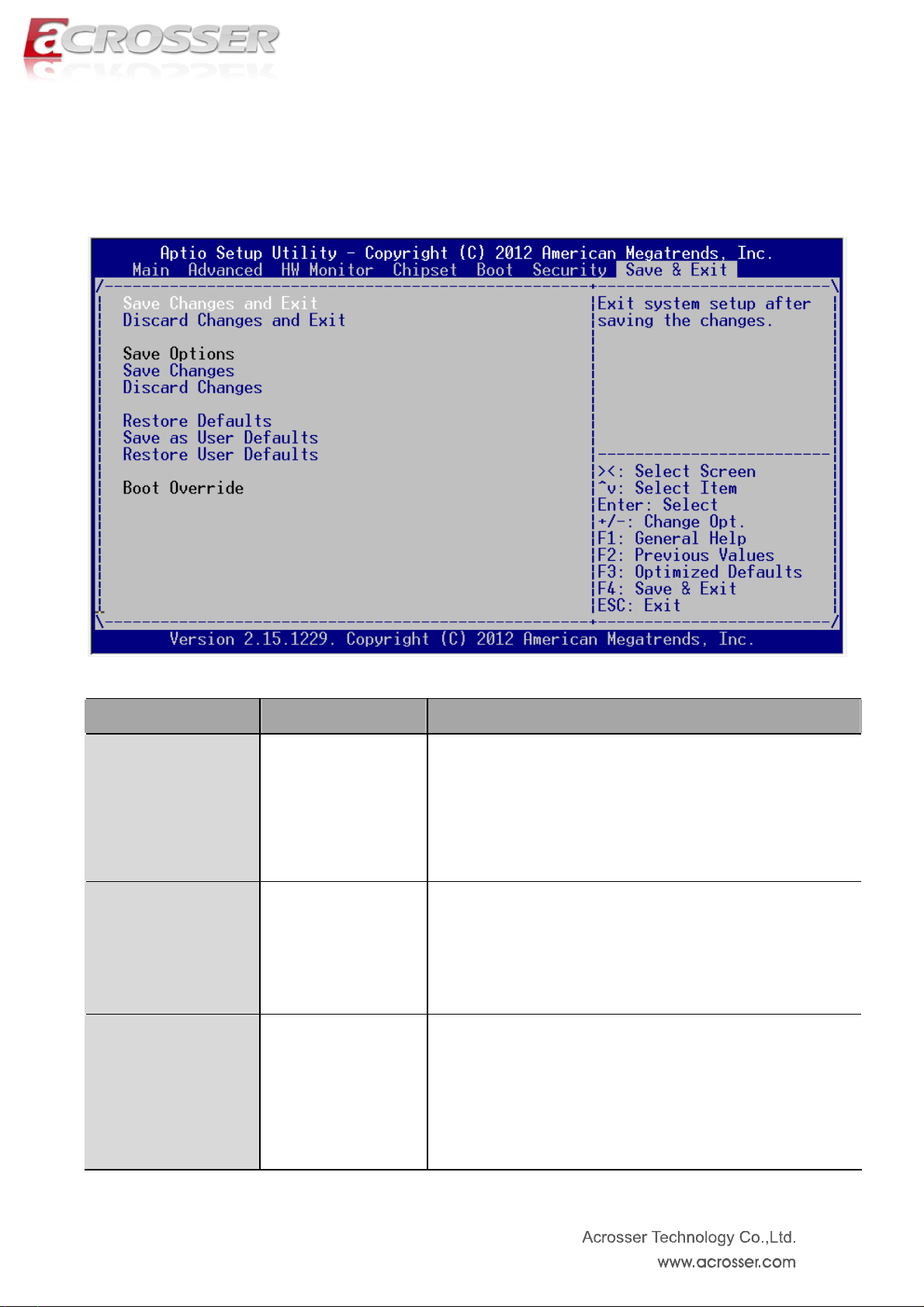
5.7. Save & Exit Setup
option Choice Description
Save Changes and Exit
Discard Changes and
Exit
Save Changes
Pressing <Enter> on
this item for save
changes and exit.
Pressing <Enter> on
this item for discard
changes and exit.
Pressing <Enter> on
this item for
confirmation : Save
Exit system setup after saving the changes.
Exit system setup without saving any changes.
Save Changes done so far to any of the setup options..
configuration
52
Page 53

Pressing <Enter> on
this item for
Discard Changes
Restore Defaults
Save as User Defaults
Restore User Defaults
confirmation:
Previous Values
Pressing <Enter> on
this item for
confirmation:
Load
Load
Optimized
Defaults
Pressing <Enter> on
this item for
confirmation:
configuration
Pressing <Enter> on
this item for
confirmation:
User Defaults
Save
Restore
Discard Changes done so far to any of the setup options.
Restore/Load Default values for all the setup options.
Save the changes done so far as User Defaults.
Restore the User Defaults to all the setup options.
confirmation:
Previous Values
Load
53
Page 54
Chapter 6 Driver And Utility Installation
6.1. Driver CD Interface Introduction
Acrosser provides the a driver CD, which includes the drivers, utilities,
applications and documents. For Windows environment, it can be guided by
the setup program; for Linux environment, the related files can be found at
folder “IB75N1\Linux”.
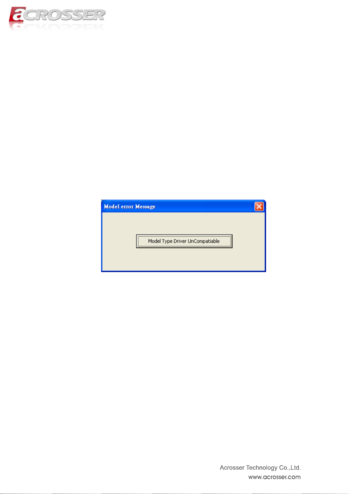
Once putting the CD into the optical disk drive, it will run automatically. The driver CD
will also detect the MB information to see if they are matched. The following error messages
appear if you get an incorrect driver CD.
It indicates that the board information is not available.
54
Page 55

6.1.1 Driver Page
This is the Driver Installation Page.
□Chipset
□LAN
□VGA
□USB3
55
Page 56

Click the icon, all the drivers will be selected.
V Chipset
V LAN
V VGA
V USB3
56
Page 57

Click the icon, all selected items will be cleared.
□Chipset
□LAN
□VGA
□USB3
57
Page 58

Click the icon to install the selected drivers.
The progress bar shows up. The main window will temporarily disappear.
Chipset
LAN
VGA
USB3
58
Page 59

Please click ‘Yes’ to restart the system.
□Chipset
□LAN
□VGA
□USB3
59
Page 60
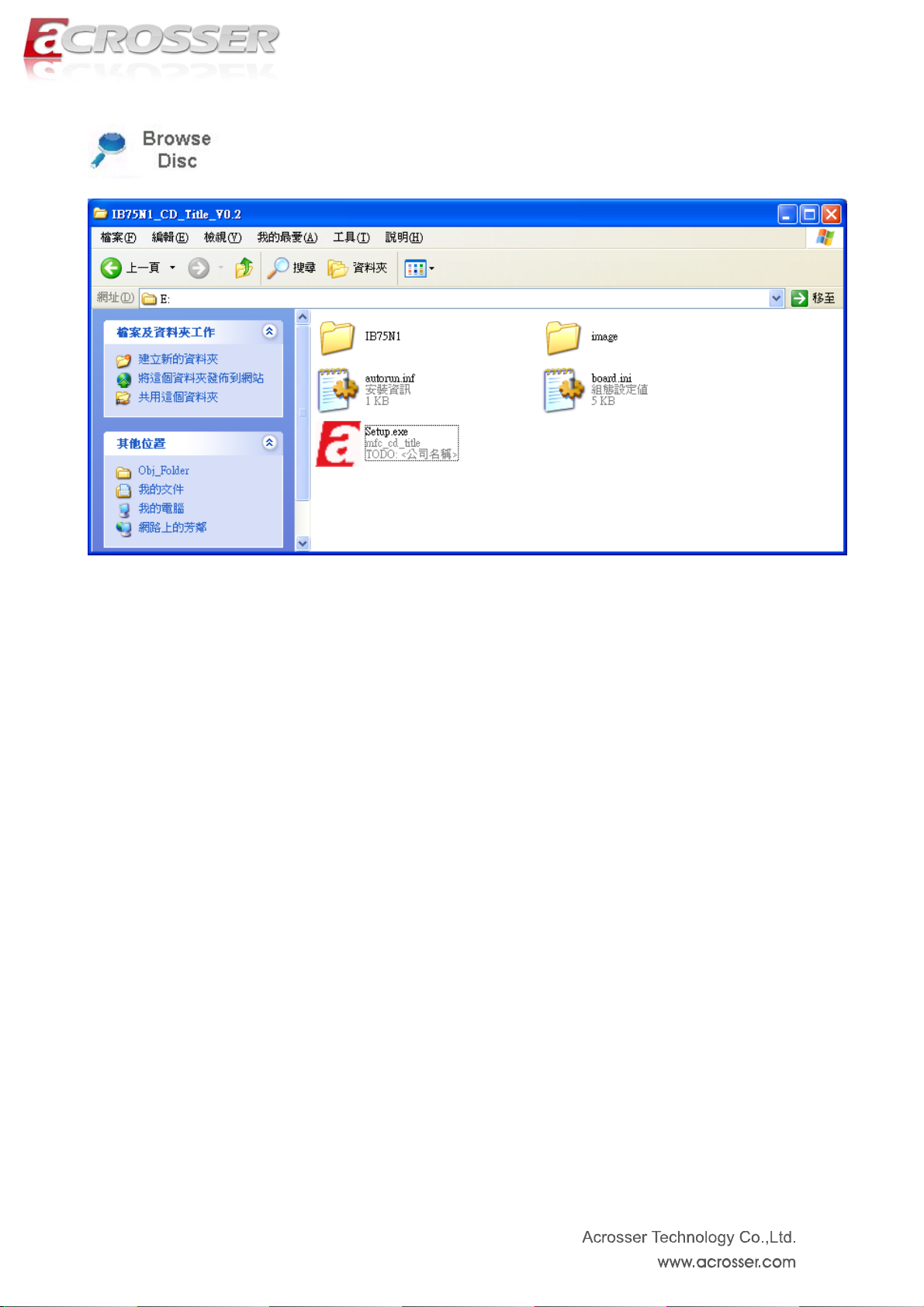
Click this icon to browse this CD content.
60
Page 61
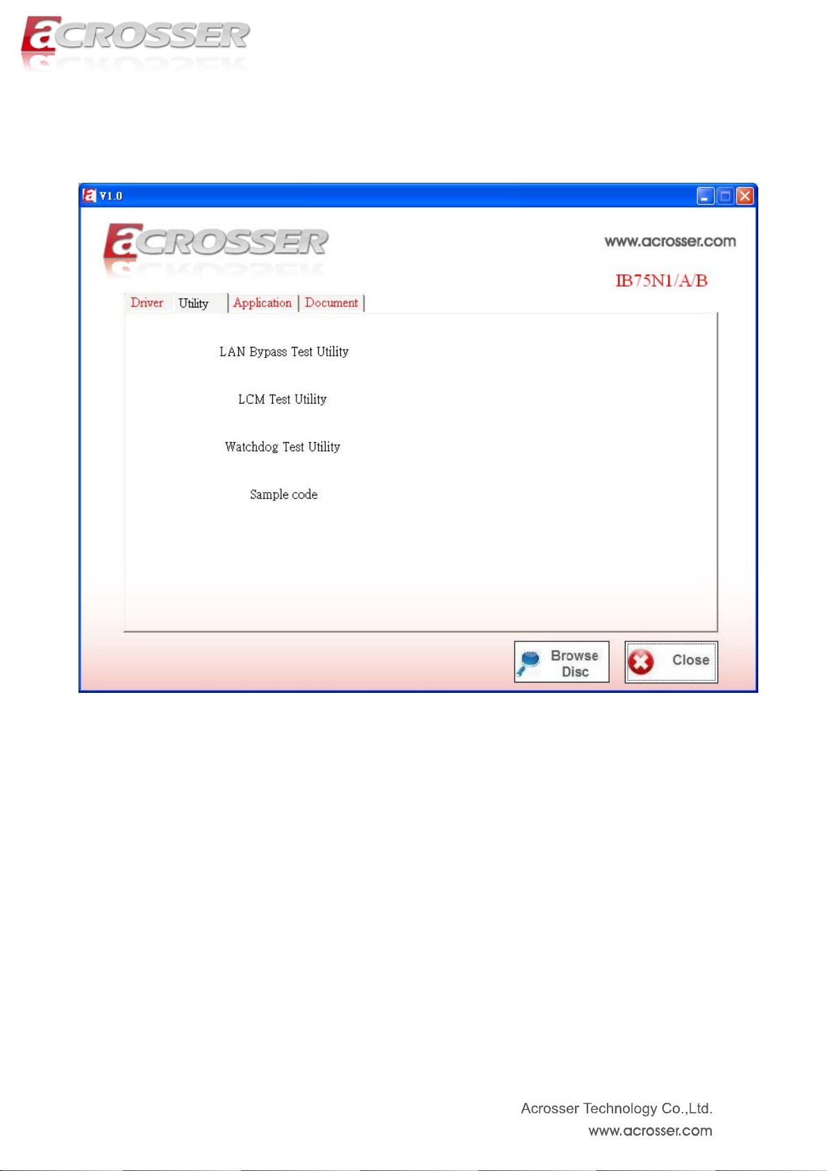
6.1.2 Utility Page
Note:
For Testing utility running completely, it should be run at test-signed kernel-mode under Operating
System x64 edition.
“BCDEdit /set testsigning on” is the introduction to run at command mode which turns test-signed
kernel-mode to on. Please refer to MSDN by following URL for more detail.
http://msdn.microsoft.com/en-us/library/windows/hardware/ff542202(v=vs.85).aspx
61
Page 62

LAN Bypass APIs Test Utility
LCM Test Utility
62
Page 63
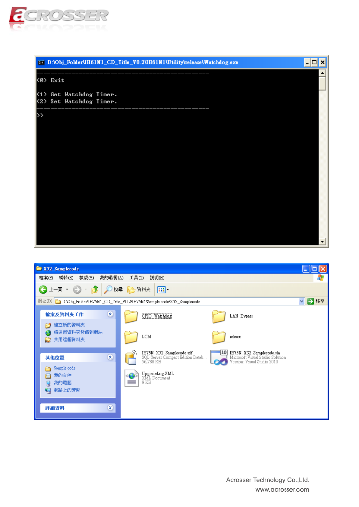
Watch Dog Test Utility
Sample code
63
Page 64

6.1.3 Application Page
64
Page 65
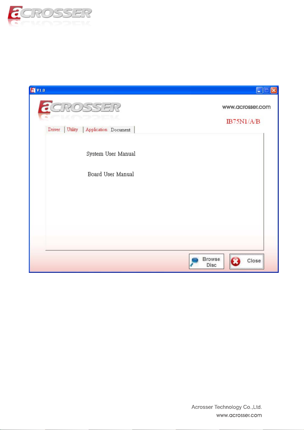
6.1.4 Documents Page
Double click on one of the items to open the manual.
Technical Support Form
65
Page 66

Chapter 7 Software Installation and
Programming Guide
7.1. Introduction
7.1.1 LCD Control Module
The LCM (short for LCD Control Module) APIs provide interfaces to control the module. By
invoking these APIs, programmers can implement the applications which have the functions listed
below:
1. Clear LCD screen.
2. Turn on or off the cursor on the screen.
3. Move the cursor on the screen.
4. Turn on or off the text on the screen.
5. Get the identification of the pressed key of the LCM.
6. Show the text on the screen.
7.1.2 Watchdog
AMB-IB75N1 provides Watchdog timer. Users can use the Watchdog APIs to configure and to
access the Watchdog timer. The Watchdog timer can be set to 1~255 seconds. Setting the timer to
zero disables the timer. The remaining seconds of the timer to reboot can be read from the timer.
In this Watchdog package, we provides:
1. Watchdog test utility.
7.1.3 LAN Bypass Subsystem
Two pairs of LAN ports on AMB-IB75N1 implement the bypass function. Users can invoke the
LAN Bypass APIs to control the bypass states of the LAN ports and set up the LAN Bypass
Watchdog timer ( this watchdog timer is different from the system watchdog timer mentioned in the
previous paragraph ).
66
Page 67

7.1.4 IB75N Library (Window platform only)
The released code for Windows platform includes a folder called ‘AMB-IB75N1’. In this folder,
there are header files and source codes of all the APIs of LCM module, Watchdog, and LAN Bypas s
functions. The source codes in this folder generate the API library ‘IB75N.lib’ and ‘IB75N.dll’. Users
who want to invoke the APIs can include the ‘IB75N.h’ in their application source code and compile
their application with the library ‘IB75N.lib’ or ‘IB75N.dll’.
Besides IB75N libraries, there are WinIo32.sys, WinIo32.lib, and WinIo32.dll in this directory.
These files are indispensable for LAN Bypass application, Watchdog application. Please put these
three files with LAN Bypass application, Watchdog application in the same folder. The APIs invoke
WinIo32.lib, WinIo32.dll, and WinIo32.sys implicitly.
7.2. File Descriptions
7.2.1 LCD Control Module
On Linux platform:
1. lcmdemo.c
This file is the source code of the demo program. This program displays the user interface,
processes user’s input, and invokes LCM APIs to demonstrates the functions of LCM.
2. lcm.h
This file includes the declarations and macro definitions needed by lcm.c.
3. serialport.h
This file includes the declarations and macro definitions needed by serialport.c.
On Window platform:
1. IB75N.h
The header of the APIs.
3. IB75N.lib and IB75N.dll
The API libraries.
67
Page 68

7.2.2 Watchdog
On Linux platform:
1. Libw83627.h
This file includes the declarations of the APIs and macro definitions.
2. maintest.c
The source code of the utility.
On Windows platform:
1. IB75N.h
The header file of the APIs.
2. IB75N.lib and IB75N.dll
The API libiaries.
7.2.3 LAN Bypass Subsystem
On Linux platform:
1. bypass.h
This file includes the declarations of the APIs and macro definitions.
2. main.c
The source code of the utility.
On Windows platform:
1. IB75N.h
The header file of the APIs.
2. IB75N.lib and IB75N.dll
The API libiaries.
68
Page 69

7.3. API List and Descriptions
7.3.1 Type Definitions
Typedef char i8;
Typedef unsigned char u8;
Typedef short i16;
Typedef unsigned short u16;
Typedef unsigned long u32;
Typedef int i32;
7.3.2 LCD Control Module
1. i32 clrscrLcm( void )
Description: Clear the screen of the LCM.
Return value: 0 after the screen is cleared.
2. i32 cursorLcm( bool mode )
Description: According to the argument ‘mode’, show the cursor on the LCM screen or eliminate
the cursor on the LCM screen. The position of the cursor is unchanged.
mode = true, show the cursor.
mode = false, eliminate the cursor.
Return value: 0 after the cursor has been shown or eliminated.
3. i32 cursorActionLcm( i32 type)
Description: According to the argument ‘type’, move the cursor to the indicated position. The
displayed text is not altered.
type = HOME, move the cursor to row 0, column 0.
type = MOVERIGHT, move the cursor to the column which is to the right of its original position
if the original column < 15.
type = MOVELEFT, move the cursor to the column which is to the left of its original position if
the original column > 0.
type = MOVEBACK, move the cursor to the column which is to the left of its original position
and delete the character at the new position if the original
column > 0.
Return value: 0 after the cursor is moved.
69
Page 70

4. i32 displayLcm( bool mode )
Description: Show the text on the LCM screen or eliminate the text on the LCM screen. The
content of the text is not altered.
mode = true, show the text.
mode = false, eliminate the text.
Return value: 0 after the text has been shown or eliminated.
5. i32 getKeyLcm( void )
Description: Scan the LCM and return the identification of the pressed direction key.
Return value: ‘UP’ if the ‘up’ direction key is pressed.
‘RIGHT’ if the ‘right’ direction key is pressed.
‘LEFT’ if the ‘left’ direction key is pressed.
‘DOWN’ if the ‘down’ direction key is pressed.
‘NONE’ if none of the keys is pressed.
6. i32 getPositionLcm( i32 *row, i32 *column )
Description: Get the position of the cursor and write the coordinate to the memory pointed at by
arguments ‘row’ and ‘column’.
Return value: 0 if the request for the coordinate has been served.
7. i32 setPositionLcm( i32 row, i32 column )
Description: Set the position of the cursor according to the arguments ‘row’ and ‘column’.
Return value: 0 after the position has been set.
-1 if the argument ‘row’ or ‘column’ meets any of the following
conditions:
(1) row is not 0.
(2) row is not 1.
(3) column is less than 0.
(4) column is greater than 15.
8. i32 showLcm( i32 length, u8 *info )
Description: Start from the current position of the cursor; print the text pointed at by ‘info’ to the
LCM screen. The number of characters to be printed is at most ‘length’. If the remaining columns
available for printing the text is less than ‘length’, the number of the characters to be printed is:
16 – ( column number of the current position of the cursor ).
Return value: 0 after the text is printed.
70
Page 71

7.3.3 Watchdog
1. Syntax:
Void wdt_start(int, int)
Description: This function read the value of the watchdog time counter and return it to the caller.
Parameters: None.
Return Value: This function return the value of the time counter and return it to the caller as an
unsigned integer.
2. Syntax:
Void wdt_stop(void)
Description: close watch dog timer.
Parameters: None.
Return Value: None.
3. Syntax:
Int get_wdt_count(void)
Description: This function get WDT_Counter.
Parameters: None.
Return Value: None.
7.3.4 LAN Bypass Subsystem
1. void enableWdt(void)
Enable Watchdog Timer. (This timer is different from the System Watchdog timer, which is
configured by the API described in 6.2).
2. void disableWdt(void)
Disable Watchdog Timer.
3. void reloadWdt(void)
Reload Watchdog Timer.
4. void forceNormal(void)
Force the port to become normal state.
71
Page 72

5. void forceBypass(void)
Force the port to become bypass state.
6. void setWdt4(void)
Set the watchdog timer to 4 seconds.
7. void setWdt8(void)
Set the watchdog timer to 8 seconds.
8. void setWdt16(void)
Set the watchdog timer to 16 seconds.
9. void setWdt32(void)
Set the watchdog timer to 32 seconds
72
Page 73

FAQ
There are 2 kinds of SATA modes --- AHCI & legacy IDE mode. When you use the Linux, We strongly
suggest to use AHCI mode. For legacy IDE mode, we found some SATA HDD could have compatibility
issue. Please confirm the BIOS setting is correct, thank you.
Does my system support Windows 8?
The system is designed and verified with Windows 7, Fedora 14 and Ubuntu 10. But, we did not verify this
system with Windows 8. Please check with Acrosser local sales rep. or authorized channels who will help you
to confirm whether we have provided new Windows 8 driver.
Where is the serial number located on my system?
The serial number (S/N) is an alpha-numeric character located on the bottom or side chassis.
Model: AMB-IB75N1
P/N:010010xxx
S/N:xxxxxxx I
CPU: i5 3550S
Memory:DDR3 2GB
My system can not connect to internet?
If your system can not connect to internet, below are a few steps you can follow to attempt to correct the
issue.
Ensure that network adapter can be recognized in Device Manager
If there is question mark or exclamation mark in the network adapter, please re-install your OS and
network driver. If the problem did not solve, please contact your local FAE or sales rep for tests.
73
Page 74

(reference only)
Ensure the Network Connections/Local Area Connection is en abled (right click and choo se “Enable”).
If the problem persists, please turn off firewall and anti-virus S/W. If the problem still exists , please
contact local FAE or service center for tests.
(reference only)
If the Network Connections/Local Area Connection is showed “limited connection” (yellow
exclamation mark), please disable and enable your connection to fix this problem. Or, you can
unplug and plug the LAN cable to fix the problem. If the problem still persists, please contact your
MIS whether there are any DHCP or IP configuration or ISP/WAN setting limitation.
74
Page 75

Appendix: Technical Support Form
We deeply appreciate you purchase Acrosser products. Please find “tech_form.doc” file in our
utility CD. If you have any questions or problems about Acrosser products, please fill in the
following information: We will answer your questions a.s.a.p.
1) Describe your info and system info
A. Your company name: _____________
B. Your contact info: _________________ & phone number: _________________
C. Your e-mail address: ______________________
D. Your company address: ___________________________________________
__________________________________________
E. Acrosser model name: _____________________
F. Acrosser Serial Number: _____________________
2) Describe system configuration
A. CPU ________________
B. Memory size ___________________
C. Storage (e.g. HDD or CF or SSD) ___________________
D. Extra peripherals (e.g. graphic card) __________________________
E. Operating system & version (e.g. Windows 7 embedded) __________________
F. Special API or driver _________________ (If ye s, please provide it for debug,)
G. Running applications _____________________
H. Other _________________________
3) Describe your problems or questions:
4) Send the above info to one of the following Acrosser contact windows:
A. Acrosser local Sales Rep
B. Acrosser authorized channels
C. Acrosser e-mail window --- http://www.acrosser.com/inquiry.html or
acrosserinfo@acrosser.com
D. Acrosser FAX number --- 886-2-29992887
75
Page 76

Acrosser Headquarters
新北市三重區重新路五段609巷12號10樓
10F., No.12, Lane 609, Sec. 5, Chongsin Rd., Sanchong District, New Taipei City 241, Taiwan, R.O.C.
TEL: +886-(0)2-2 9999 000
FAX: +886-(0)2-2999-2887
acrosserinfo@acrosser.com
Acrosser Taichung Office
台中市南屯區河南路四段162號12樓之6
12-6, No.162, Sec. 4, Henan Rd., Nantun Dist., Taichung City 408, Taiwan R.O.C.
TEL: +886-(0)4-2251-0659
FAX: +886-(0)4-2254-6079
Acrosser China Subsidiary
欣扬通电子有限公司 深圳分公司
深圳市福田区车公庙泰然九路21号 皇冠科技园3栋2楼东面A区 (邮编:518040)
A East 2F 3th Building, Crown Estate No.21, 9 Tai-Ran Road, Che Gong Miao, Futian Dist, Shenzhen, China
(Postal:518040)
TEL :+86-0755-83542210/2230/2240/2250/2260
FAX :+86-0755-83700087
Acrosser Shanghai Office
欣扬通电子有限公司 上海分公司
上海市徐汇区零陵路631号爱乐大厦12E (邮编:200085)
12E, Aile Building, No.631, Ling-ling Road, Xu-hui Dist, Shanghai, China (Postal:200085)
TEL :+86-021-64288853
FAX :+86-021-64288854
Acrosser Beijing Office
欣扬通电子有限公司 北京分公司
北京市海淀区安宁庄西三条9号宜品上层2-703(邮编:100085)
Room 2-703,Yipinshangceng,No.9,Xisantiao,Anning Zhuang,Haidian Dist,Beijing (Postal:100085)
TEL :+86-010-82359009
FAX :+86-010-82359003
Acrosser USA Subsidiary
11235 Knott Ave. Suite A, Cypress, CA 90630, USA
Toll Free: +1-866-401-9463
TEL: +1-714-903-1760
FAX: +1-714-903-5629
info@acrosserusa.com
76
 Loading...