

Page 1

AMB-D525N2 Board
User Manual
1
Page 2

Copyright
All Rights Reserved.
Manual’s first edition:
For the purpose of improving reliability, design and function, the information in this
document is subject to change without prior notice and does not represent a
commitment on the part of the manufacturer.
The manufacturer shall not be liable for direct, indirect, special, incidental, or
consequential damages arising out of the use or inability to use the product or
documentation, even if advised of the possibility of such damages.
This document contains proprietary information protected by copyright. All rights
are reserved. No part of this manual may be reproduced by any mechanical, electronic,
or other means in any form without prior written permission of the manufacturer.
Trademarks
AMB-D525N2 is a registered trademark of Acrosser; IBM PC is a registered
trademark of the International Business Machines Corporation; Atom is a registered
trademark of Intel Technologies Inc; Phoenix SecureCore is a registered trademark of
Phoenix Technologies; other product names mentioned herein are used for
identification purposes only and may be trademarks and/or registered trademarks of
their respective companies.
2
Page 3

Table of Contents
Chapter 1 Introduction......................................................................... 4
1.1. ............................................................................................................4 Specifications
1.2. ......................................................................................................5 Package Contents
Chapter 2 H/W Information................................................................. 6
2.1. Mainboard illustration...............................................................................................6
2.2. Headers and Jumper Settings ....................................................................................7
Chapter 3 BIOS Settings.....................................................................11
3.1. Main Setup ..............................................................................................................12
3.1.1 IDE Primary/Master and Primary/Slave Setup ................................................14
3.1.2 SATA Port 1~2 Setup........................................................................................15
3.2. Advanced Setup.......................................................................................................16
3.2.1. CPU Control Sub-Menu Setup........................................................................17
3.2.2. Video (Intel IGD) Control Sub-Menu Setup...................................................18
3.2.3. ICH Control Sub-Menu Setup.........................................................................19
3.2.4. LPC Control Sub-Menu Setup ........................................................................23
3.2.5. Boot Features Setup.........................................................................................24
3.2.6. Console Redirection Setup..............................................................................25
3.3. Security Setup..........................................................................................................26
3.4. Power Setup.............................................................................................................27
3.5. Boot Setup...............................................................................................................28
3.6. Exit Setup................................................................................................................29
3
Page 4

Chapter 1 Introduction
AMB-D525N2 with Intel Atom D525 processor is a networking microbox, which is a
small, cost-effective and entry level solution. By four 10/100/1000Mbps LANs, the
AMB-D525N2 is sufficient for the small business security hardware solution.
1.1. Specifications
Intel Atom D525
CPU
Dual-core, clock speed 1.8G,TDP 13W
Chipset Intel ICH8M,TDP 2.4 W
Display 1 * VGA (Pin Header)
Support DDR3 800MHz
Memory
Storage
Ethernet
Console Port 1 * Console Port (1 x RJ45)
Other Ports
Temperature
BIOS
OS Support
1 * 204-pin SO-DIMM slot,Up to 4 GB
2 * Serial ATAII ports (3Gbps)
1 * CF socket
1 * 2.5” HDD Bay
4 * Realtek 8111E PCI-E 1000Mbps LAN
2 * USB2.0 (2 * Rear I/O)
1 * Mini PCIe (Wireless devices are supported)
Operating: 0~40℃
Phoenix BIOS
Windows XP 32-bit, Windows 7 32-bit, Fedora 17 32-bit
4
Page 5

1.2. Package Contents
Check if the following items are included in the package.
1 x AMB-D525N2
1 x Quick Manual
1 x Driver CD
1 x Console Cable
1 x SATA Cable
1 x SATA Power Cable
1 x Power Adaptor
5
Page 6

Chapter 2 H/W Information
This chapter describes the installation of AMB-D525N2. At first, it shows the
Function diagram and the layout of AMB-D525N2. It then describes the unpacking
information which you should read carefully, as well as the jumper/switch settings
for the AMB-D525N2 configuration.
2.1. Mainboard illustration
CPU
Intel ATOM D525 CPU
DIMM1
204-Pin DDR3 SO-DIMM Socket
CF1
CF card Socket
Chipset
Intel ICH8M chipset
MINIPCIE1
Mini PCI-Express Slot
Note: CF1 does not support PIO mode.
6
Page 7

2.2. Headers and Jumper Settings
ATX2
DC power input connector
CPU_FAN1
CPU fan connector
SYS_FAN1
System fan connector
F_PANEL2
Front panel 2 header
F_PANEL1
Front panel 1 header
PW_LED1
Power LED header.
HD_LED1
HDD LED header.
LAN_LED4
LAN 4 LED header.
LAN_LED3
LAN 3 LED header
LAN_LED2
LAN 2 LED header
LAN_LED1
LAN 1 LED header
JP7
CF Card power supply control jumper
JP8
CF Card Working Mode Selecting
Jumper
P_SATA1~2
SATA1~2 power supply connector.
CLR_CMOS1
Clear CMOS header.
S_ATA1
SATA1 device connector
J3
Debug header (Reserve)
S_ATA2
SATA2 device connector
R_USB1*
USB connector
COM1
RJ45 COM connector
RJ45_J1
RJ45 LAN1 connector
RJ45_J2
RJ45 LAN2 connector
RJ45_J3
RJ45 LAN3 connector
RJ45_J4
RJ45 LAN4 connector
VGA2
VGA expansion header
*Note. It can not use USB Hub with power adaptor that connects to USB port.
7
Page 8

2. CPU Fan Connector (3*1 Pin 2.54 mm)
Location Header Pin Definition Pin Definition
1
GND
2 + 12V
CPU_FAN1
3 FAN IO
3. System Fan Connector (3*1 Pin 2.54 mm)
Location Header Pin Definition Pin Definition
1 GND 2 + 12V
SYS_FAN1
3 + 5V
4. Front Panel2 Header (3*1 Pin 2.54mm)
Location Connector Pin Definition Pin Definition
1 N/C 2 PWR_SW+
F_PANEL2
3 PWR_SW-
5. Front Panel1 Header (3*1 Pin 2.54mm)
Location Connector Pin Definition Pin Definition
1 GND 2 RST_SW+
F_PANEL1
3 RST_SW-
6. Power LED Header (2*1 Pin 2.54mm)
Location Connector Pin Definition Pin Definition
PW_LED1
1 PWR_LED+ 2 PWR_LED-
7. HD LED Header (2*1 Pin 2.54mm)
Location Connector Pin Definition Pin Definition
HD_LED1
1 HD_LED+ 2 HD_LED-
8
Page 9

8~11. LAN LED Headers (2*1 Pin 2.54mm)
Location Connector Pin Definition Pin Definition
LAN_LED
(1、2、3、4)
1 LAN_ACT+ 2 LAN_ACT-
12. CF Card Power Supply Control Jumper (3*1 Pin 2.54mm)
Location Jumper Setting Function
JP7
1-2 5V Power Supply
2-3(Default) 3.3V Power Supply
13. CF Card Working Mode Selecting Jumper (3*1 Pin 2.54mm)
Location Jumper Setting Function
1-2(Default) IDE Master
JP8
2-3 IDE Slave
14. SATA1~2 Power Supply Connector (4*1 Pin 2.0mm)
Location Connector Pin Definition Pin Definition
1 + 12V 2 GND
P_SATA1
3 GND 4 + 5V
15. CMOS Clear Header (3*1 Pin 2.54mm)
Location Jumper Setting Function
1-2(Default) Normal
CLR_CMOS
2-3 Clear CMOS
9
Page 10

25. VGA Expansion Header (12*1 Pin 2.0mm)
Location Header Pin Definition Pin Definition
1 GND 2 VSYNC
3 HSYNC 4 GND
VGA2
5 RED 6 GND
7 GREEN 8 GND
9 BLUE 10 GND
11 DDC_DATA 12 DDC_CLK
10
Page 11

Chapter 3 BIOS Settings
This chapter describes the BIOS menu displays and explains how to perform
common tasks needed to get the system up and running. It also gives detailed
explanation of the elements found in each of the BIOS menus. The following topics are
covered:
Main Setup
Advanced Setup
Security Setup
Power Setup
Boot Setup
Exit Setup
11
Page 12

3.1. Main Setup
Once you enter the Setup Utility, the Main menu will appear on the screen. Use the
arrow and Enter keys to highlight the item and then use the < + > < - > keys to select
the value you want in each item.
Note: Listed at the bottom of the menu are the control keys. If you need any help with
the item fields, you can press the <F1> key, and it will display the relevant information.
Option Choice Description
System Time
System Date
AHCI Config
N/A Set the time. Use Tab to switch between Time elements
N/A Set the date. Use Tab to switch between Date elements
IDE/AHCI Default is IDE mode. Set AHCI mode need driver.
12
Page 13

IDE Primary/Master
IDE Primary/Slave
SA TA Port 1~2
Installed Memory
Available to OS
Used by devices
BIOS
N/A This item displays the IDE disk driver info
N/A This item displays the IDE disk driver info
N/A This item displays the SATA disk driver info
N/A This item displays the motherboard memory size
N/A This item displays the available memory size to OS
N/A This item display the used memory size
N/A This item display the BIOS version
13
Page 14
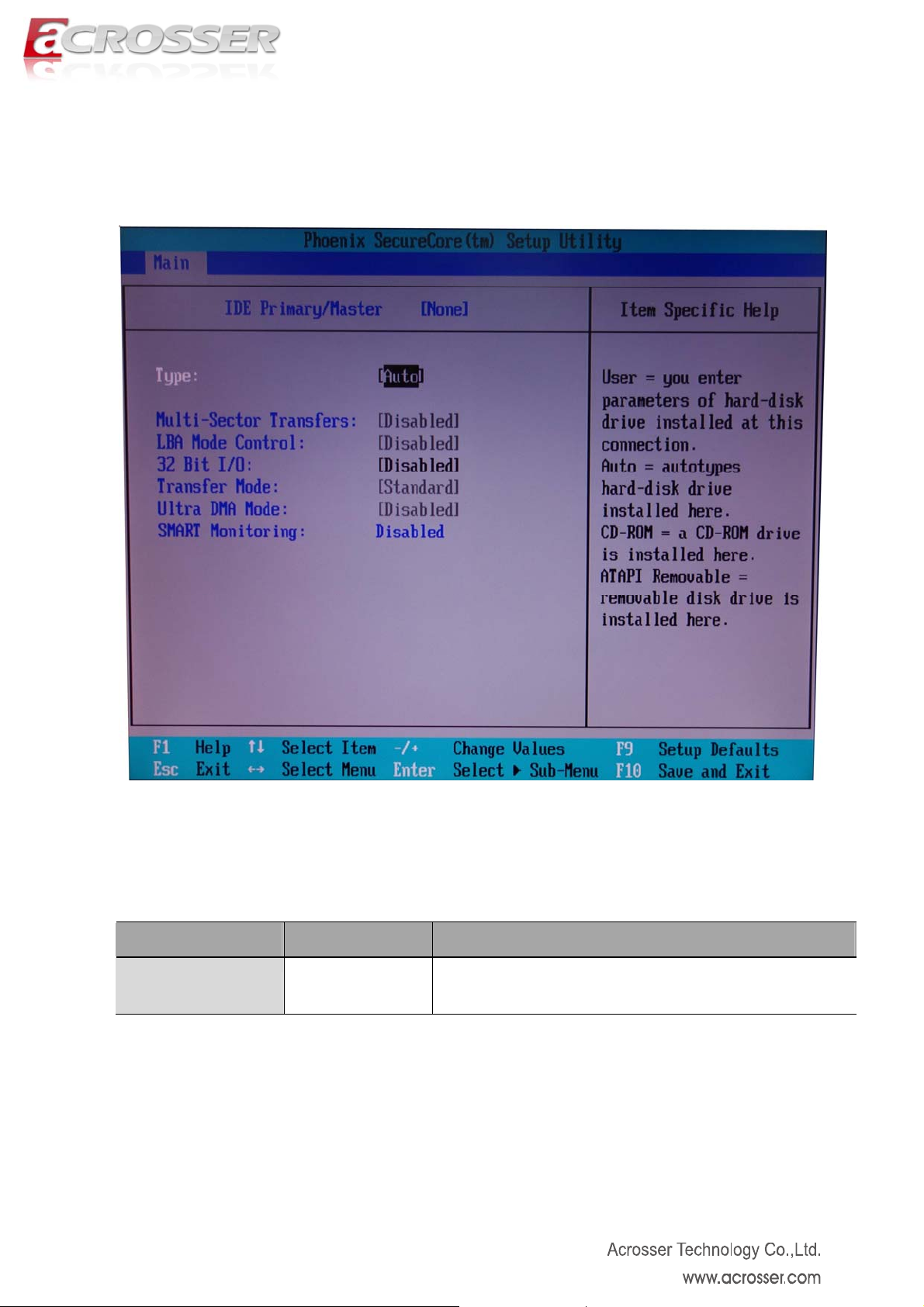
3.1.1 IDE Primary/Master and Primary/Slave Setup
Note: We suggest to remain the default “Auto” setting. System will auto detect the
installed IDE device driver. Unless you are familiar with IDE device driver, please
don’t change the settings.
Option Choice Description
Type
Auto/CD-ROM/
ATAPI/User/None
This item display the installed IDE device driver type
14
Page 15

3.1.2 SATA Port 1~2 Setup
Note: We suggest to remain the default “Auto” setting. System will auto detect the
installed SATA device driver. Unless you are familiar with SATA device driver, please
don’t change the settings.
Option Choice Description
Type
Auto/CD-ROM/
ATAPI/User/None
This item display the installed SATA device driver type
15
Page 16

3.2. Advanced Setup
Option Choice Description
CPU Control
Sub-Menu
Video Control
Sub-Menu
ICH Control
Sub-Menu
LPC Control
Sub-Menu
Boot Feature
Console Redirection
Legacy USB
Support
N/A This item contains CPU parameters.
N/A This item contains internal video configuration parameters.
N/A This item contains ICH parameters.
N/A This item contains LPC I/O devices parameters.
N/A Select boot features.
N/A This item contains console parameters.
Enabled, Disabled Enable/Disable support of legacy USB
16
Page 17
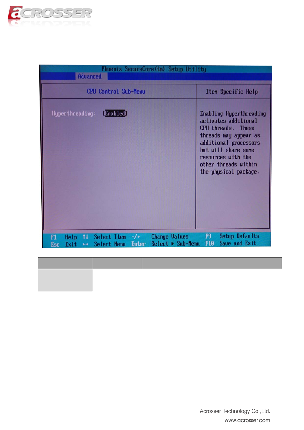
3.2.1. CPU Control Sub-Menu Setup
Option Choice Description
Hyperthreading
Enabled, Disabled Enable/Disable support of CPU hyperthreading.
17
Page 18
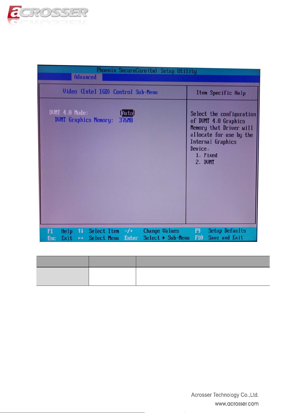
3.2.2. Video (Intel IGD) Control Sub-Menu Setup
Option Choice Description
DVMT 4.0 Mode
Auto, Fixed, DVMT Set Intel IGD video mode
18
Page 19
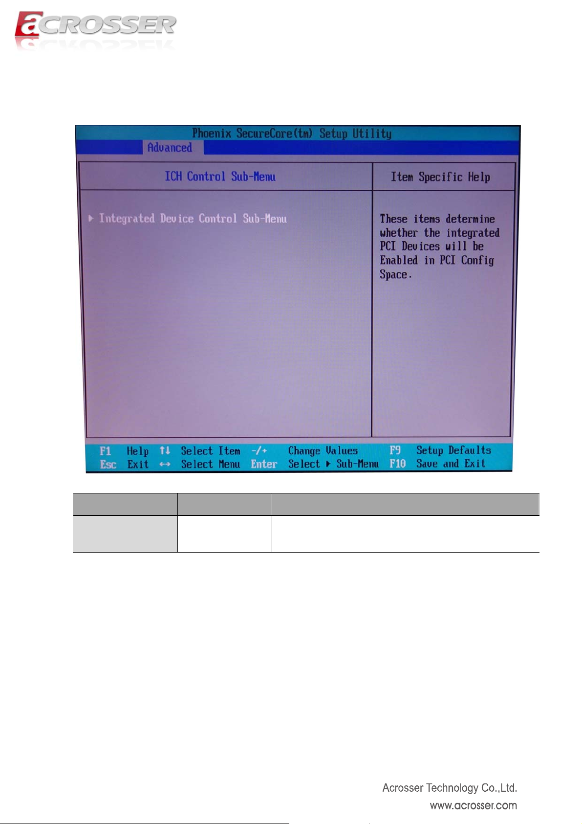
3.2.3. ICH Control Sub-Menu Setup
Option Choice Description
IDC Sub-Menu
N/A Set IDC sub-menu
19
Page 20

Option Choice Description
PCI Express
Sub-Menu
ICH USB Sub-Menu
N/A Set PCI Express parameters
N/A Set USB parameters
20
Page 21

3.2.3.1. PCI Express Control Sub-Menu Setup
Option Choice Description
PCI Express
Root Port 1
PCI Express
Root Port 2~4
Root Port SAPM
Support
Auto, Disabled,
Enabled
Auto, Disabled,
Enabled
Auto, Disabled This item define ASPM parameter.
Set PCI Express Port 1 auto/enabled/disabled. If Port 1 is
disabled, Port 2~4 will be disabled.
Set PCI Express Port 2~4 auto/enabled/disabled.
21
Page 22

3.2.3.2. ICH USB Control Sub-Menu Setup
USB Dev #29
USB Dev #26
Option Choice Description
Disabled,
Fun #0,
Fun #0, 1,
Fun #0, 1, 2,
Fun #0, 1, 2, 3, 7
Disabled,
Fun #0, 7
Fun #0, 1, 7
Control USB Dev #29
Control USB Dev #26
22
Page 23

3.2.4. LPC Control Sub-Menu Setup
Option Choice Description
COM 1
I/O address, IRQ
Auto, Enabled
This item set COM 1 enabled/disabled/auto.
Disabled
3F8/IRQ 4
2F8/IRQ 3
Set COM 1 I/O address and IRQ.
3E8/IRQ 4
2E8/IRQ 3
23
Page 24

3.2.5. Boot Features Setup
Option Choice Description
Summary Screen
QuickBoot Mode
Disabled, Enabled Display system configuration on boot.
Disabled, Enabled Disable/Enable the system to skip some tests while booting.
24
Page 25

3.2.6. Console Redirection Setup
Option Choice Description
Com Port Address
Baud Rate
Flow Control
Control connection
Continue C.R.
after POST
# of video pages
Disabled,
On-board COM A
rates Set COM port baud rate, e.g. 9600, 19200 or 38400
None, XON/XOFF,
CTS/RTS
Direct, Modem Indicate COM port is connected to system or modem.
On, Off Enable/Disable Console Redirection after OS has loaded
1 ~ 8 Number of video pages for Console Redirection
Enable/Disable on-board COM port A.
Set COM port flow control
25
Page 26

3.3. Security Setup
Option Choice Description
Set Supervisor
Password
Set User Password
Password on boot
N/A Set the administrator password
N/A Set the user password
Enabled, Disabled Enable/Disable password on system boot
26
Page 27

3.4. Power Setup
Option Choice Description
Power Button
Behavior
After Power Failure
On/Off,
Wake/Sleep
Stay Off,
Last State,
Power On
Select the system power state after press power button.
Set the operation mode if power loss occurs.
27
Page 28
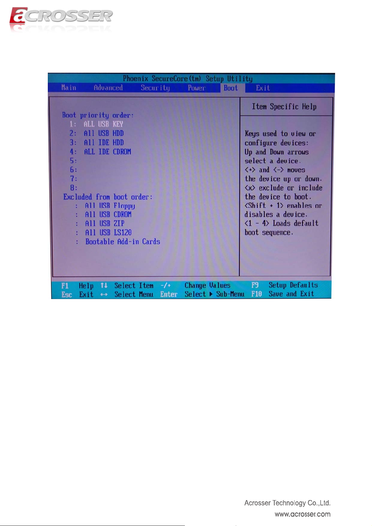
3.5. Boot Setup
View and configure the boot devices priority
28
Page 29

3.6. Exit Setup
Option Choice Description
Exit
Saving Changes
Exit
Discarding Changes
Load Setup Default
Discard Changes
Yes, No Save configure change and reset the system.
Yes, No Without save any changes and reset the system.
Yes, No Load default configuration.
Yes, No Discard changes done so far to any of the setup options.
29
Page 30

Save Changes
Yes, No Save configuration changes.
30
 Loading...