

Page 1

1
AMB-IH61T3 Board
User Manual
Page 2

2
Copyright
All Rights Reserved.
Manual’s first edition:
For the purpose of improving reliability, design and function, the information in this
document is subject to change without prior notice and does not represent a
commitment on the part of the manufacturer.
The manufacturer shall not be liable for direct, indirect, special, incidental, or
consequential damages arising out of the use or inability to use the product or
documentation, even if advised of the possibility of such damages.
This document contains proprietary information protected by copyright. All rights
are reserved. No part of this manual may be reproduced by any mechanical, electronic,
or other means in any form without prior written permission of the manufacturer.
Trademarks
AMB-IH61T3 is a registered trademark of Acrosser; other product names
mentioned herein are used for identification purposes only and may be trademarks
and/or registered trademarks of their respective companies.
Page 3

3
Table of Contents
Chapter 1 Introduction ............................................................. 4
1.1. Specifications............................................................................................. 4
1.2. Package Contents ...................................................................................... 6
Chapter 2 H/W Information ...................................................... 7
2.1. Mainboard illustration ............................................................................... 7
2.2. Headers and Jumper Settings .................................................................. 9
Chapter 3 BIOS Settings ........................................................ 15
3.1. Main Setup ............................................................................................... 16
3.2. Advanced Setup ...................................................................................... 18
3.2.1. ACPI Settings Setup ........................................................................ 19
3.2.2. Power On Setup ............................................................................... 20
3.2.3. LVDS Configuration Setup .............................................................. 21
3.2.4. CPU Configuration Setup ................................................................ 22
3.2.5. SATA Configuration Setup .............................................................. 23
3.2.6. Super I/O Setup ................................................................................ 24
3.2.7. Hardware Monitor Setup ................................................................. 27
3.2.8. COM7/8/9/10 Configuration Setup .................................................. 28
3.3. Chipset Setup .......................................................................................... 30
3.3.1 PCH-IO Configuration Setup ............................................................ 31
3.3.2. System Agent Configuration Setup................................................ 36
3.4. Boot Setup .................................................................................................. 39
3.5. Security Setup ............................................................................................ 40
3.6. Save & Exit Setup ...................................................................................... 41
FAQ .......................................................................................... 43
Page 4

4
Chipset
Intel H61
Ethernet
Serial
10 * RS232 Headers
1 * LVDS port
1 * CPU_FAN Socket
Windows XP, Window 7 (32bit), Fedora 17 32bit
Chapter 1 Introduction
AMB-IH61T3 with Intel Pentium/Core i3/i5/i7 processor is a multi-function Industrial
main-board, which is suitable for using in all kind of applications. Besides it basic I/O
ports like VGA, USB, COM. LAN, and GPIO, it can expand to 10 x COM ports.
1.1. Specifications
Support Intel Pentium/ 2nd and 3rd Generation Core i3/5/7 CPU,
CPU
LGA1155
Memory
Support DDR3 1066/1333 MHz
2 * DIMM Slot,Up to 16 GB Memory Size
2 * Realtek 8111E/8105E PCI-E LAN
Storage 2 * Serial ATA II ports
[2]
GPIO 8* GPIO (4 * IN and 4 * OUT)
2* VGA DB15 port
Graphic
Realtek ALC662 5.1 Channel HD Audio Codec
Audio
Line-out /MIC Ports and onboard Header
1 * PS/2 port for keyboard
1 * LPT DB25 port
8 * USB2.0 ports (4 * Rear I/O + 4 * Header)
Other ports
1 * Mini PCI-E
1 * PCI-E X16 slot
[1]
1 * SYS_FAN Socket
Storage: -20~75℃
Temperature
Operating: 0~50℃
OS Support
Page 5

5
170 x 170mm
Dimension
Notes:
[1]: Due to the restriction of Windows 32 bit OS, when applied more than 4G
memory, 32 bit OS may detect less than actual size.
[2]: COM3 can be RS232 or RS485 by setting jumpers.
[3]: It is recommended to use CPUs those TDP no higher than 77W.
Page 6

6
1.2. Package Contents
Check if the following items are included in the package.
1 x AMB-H61T3 main board
1 x Quick Manual
1 x Utility CD
1 x SATA Cable
1 x DB9 cable for 1 COM port
2 x DB9 cable for 4 COM port
1 x IO Shield
1 x Cooler Module
Page 7
7
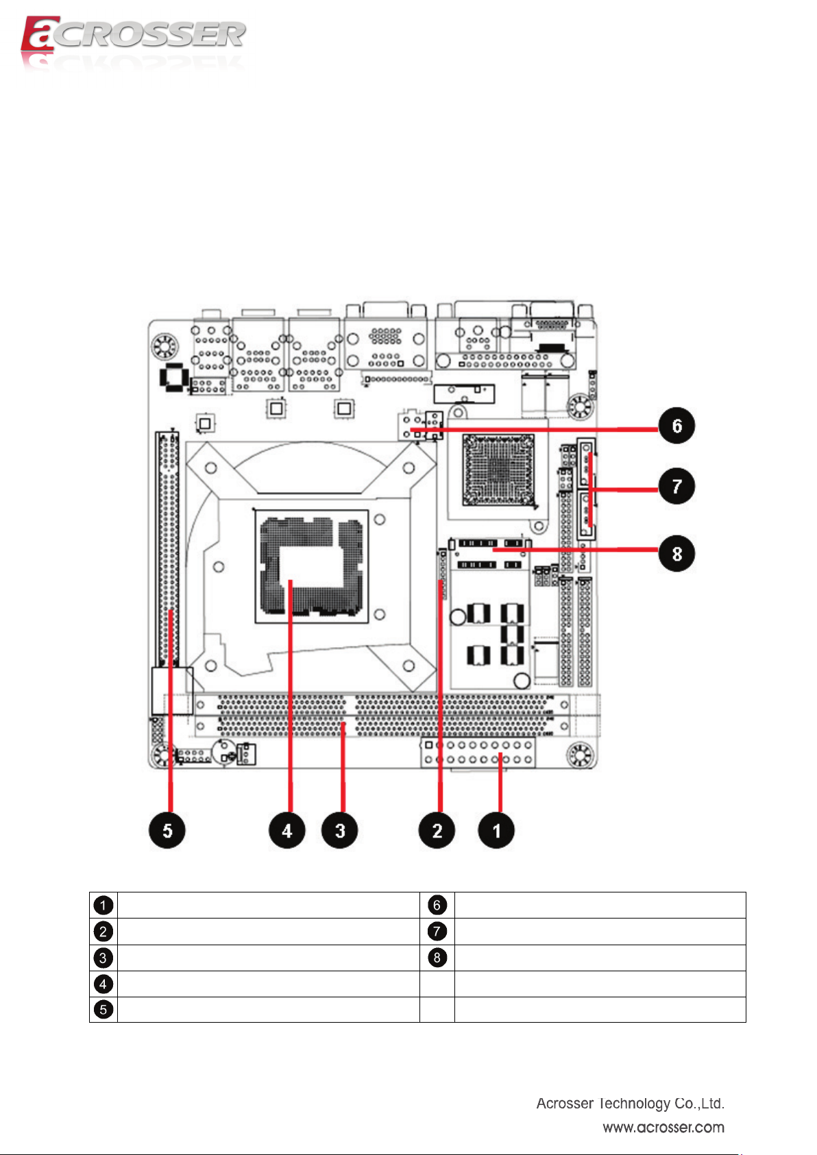
Chapter 2 H/W Information
This chapter describes the AMB-IH61T3 jumper and switch settings.
2.1. Mainboard illustration
ATX2 Power Supply Connector
Debug Header
DIMM Slot
CPU Socket
PCI-E x 16 Slot
ATX1 Power Supply Connector
SATA Connector
Mini PCI-E Slot
Page 8

8
LPT Connector
COM Connector
LAN Connectors
Audio Connector
VGA2 Connector
PS/2 Connector
VGA1 Connector
USB Connectors
Note. It can not use USB Hub with power adaptor that connects to USB port.
Page 9

9
2.2. Headers and Jumper Settings
COM3~6 Header
COM2 Header
COM3 Signal Selection Jumpers
System FAN Connector
Front Panel Header
GPIO Header
Audio Header
CPU FAN Connector
Front USB Headers
CMOS Clear Jumper
LVDS VDD Selection Jumper
LVDS Signal Header
LVDS Backlight Control Header
RS-485 Header
COM7~10 Headers
Page 10
10
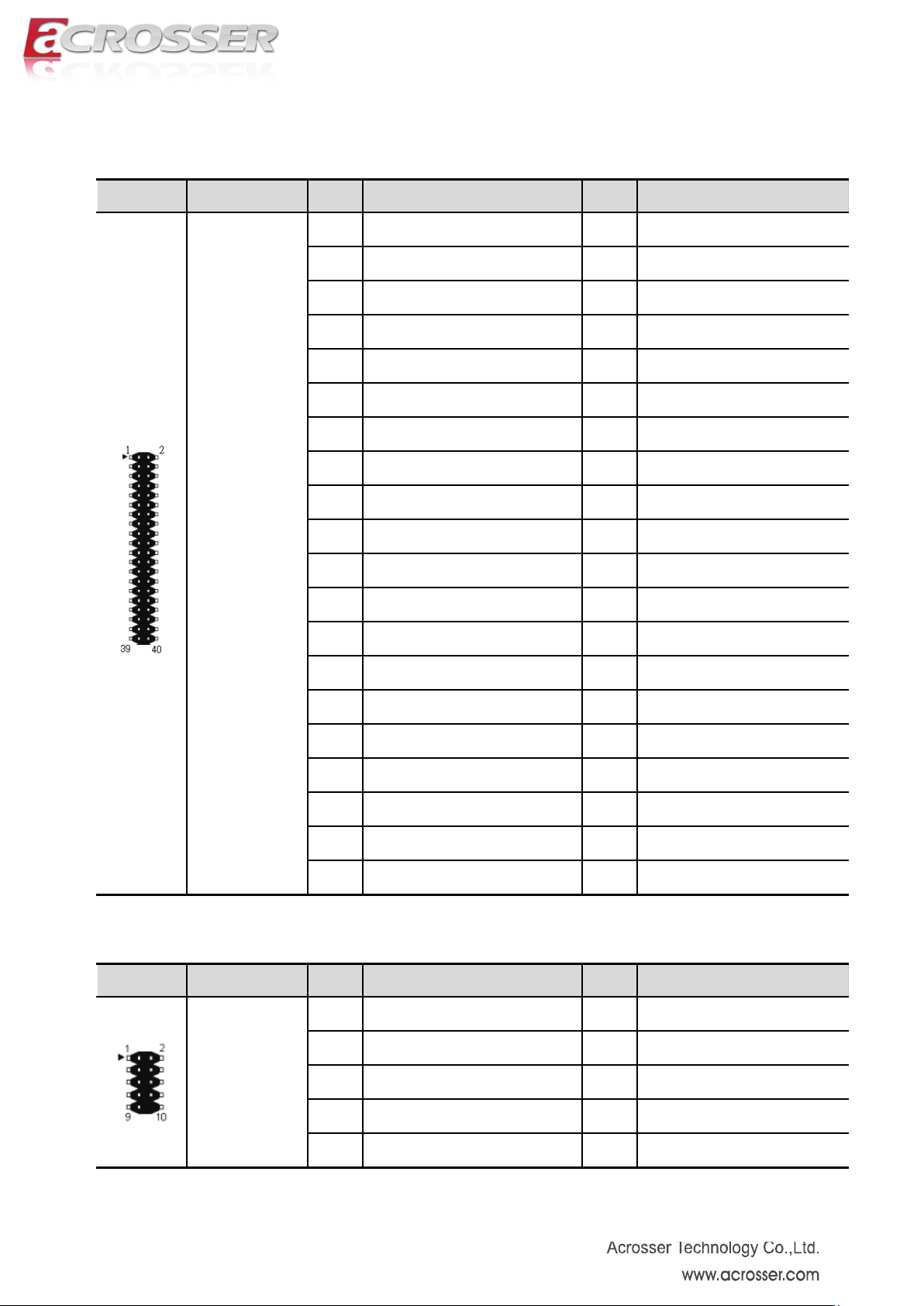
[1] COM3-6 Headers(20*2 Pin 2.00 mm)
Location Header Pin Definition Pin Definition
1 COM3_DCD 2 COM3_RXD
3 COM3_TXD 4 COM3_DTR
5 GND 6 COM3_DSR
7 COM3_RTS 8 COM3_CTS
9 COM3_RI 10 GND
11 COM4_DCD 12 COM4_RXD
13 COM4_TXD 14 COM4_DTR
15 GND 16 COM4_DSR
17 COM4_RTS 18 COM4_CTS
J_COM3-6
19 COM4_RI 20
21 COM5_DCD 22 COM5_RXD
23 COM5_TXD 24 COM5_DTR
25 GND 26 COM5_DSR
27 COM5_RTS 28 COM5_CTS
29 COM5_RI 30 GND
31 COM6_DCD 32 COM6_RXD
33 COM6_TXD 34 COM6_DTR
35 GND 36 COM6_DSR
37 COM6_RTS 38 COM6_CTS
39 COM6_RI 40 GND
[2] COM2 Header (5*2 Pin 2.54mm)
Location Header Pin Definition Pin Definition
1 DCD 2 DSR
3 RXD 4 RTS
J_COM2
5 TXD 6 CTS
7 DTR 8 RI
9 GND
Page 11
11
9
GPI17(0x50E,bit 1)
10
+ 3.3V
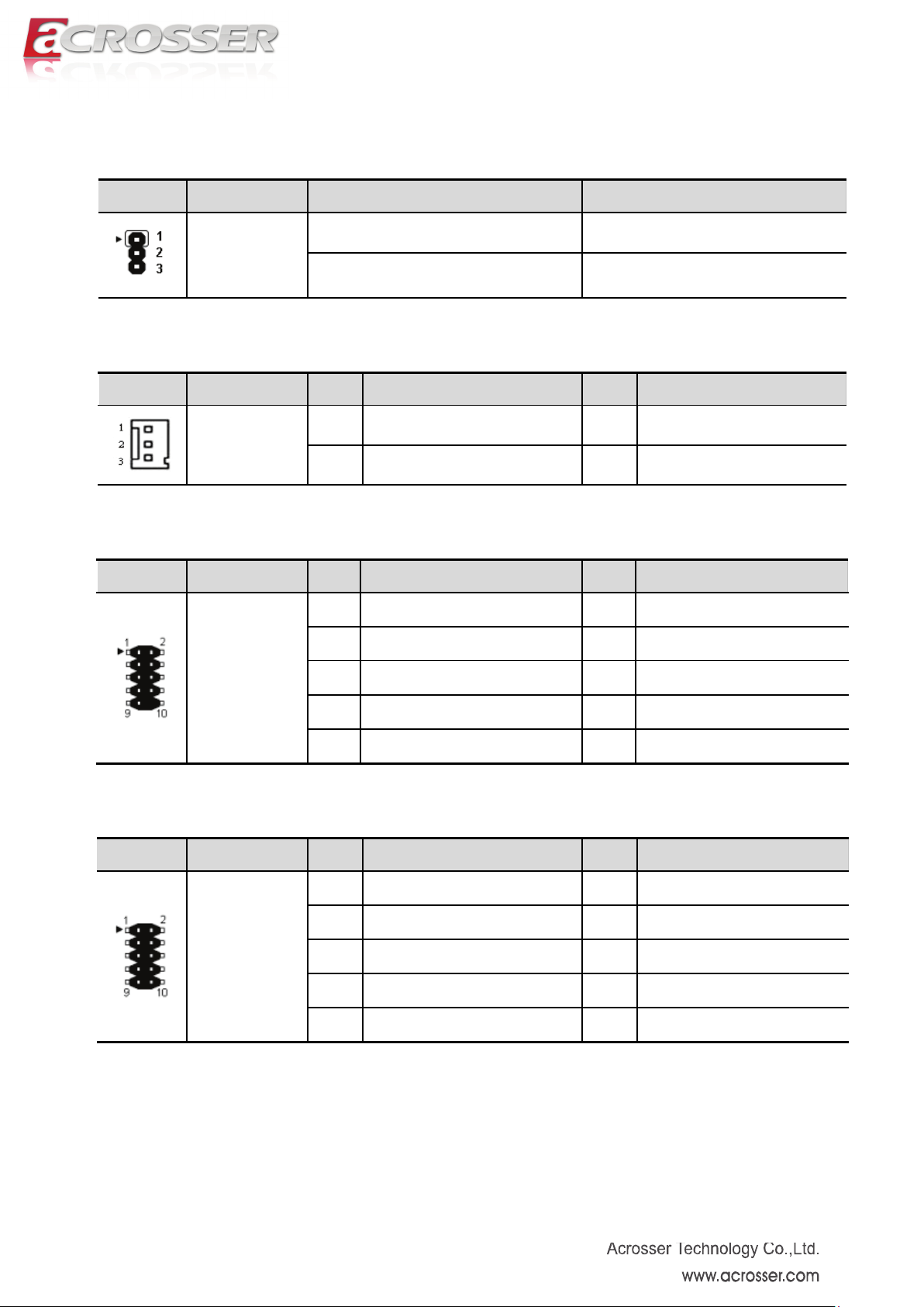
[3] COM3 Signal selection Jumpers (3*1 Pin 2.0mm)
Location Jumper Setting Function
JP1
JP2
1-2 RS232
2-3
RS485
[4] System Fan Connector (3*1 Pin 2.54 mm)
Location Connector Pin Definition Pin Definition
1 GND 2 +12V
SYS_FAN
3 FAN TAC
[5] Front Panel Header(5*2 Pin 2.54 mm)
Location Header Pin Definition Pin Definition
1 HD LED+ 2 Power LED+
3 HD LED- 4 Power LED-
F_PANEL1
5 RESET- 6 PWR+
7 RESET+ 8 PWR -
9 N/C 10
[6] GPIO Header(5*2 Pin 2.00 mm)
Location Header Pin Definition Pin Definition
1 GPO68(0x548,bit 4) 2 GPO69(0x548,bit 5)
3 GPO70(0x548,bit 6) 4 GPO71(0x548,bit 7)
J_GPIO1
5 GND 6 GPI1(0x50C,bit 1)
7 GPI6(0x50C,bit 6) 8 GPI7(0x50C,bit 7)
Page 12
12
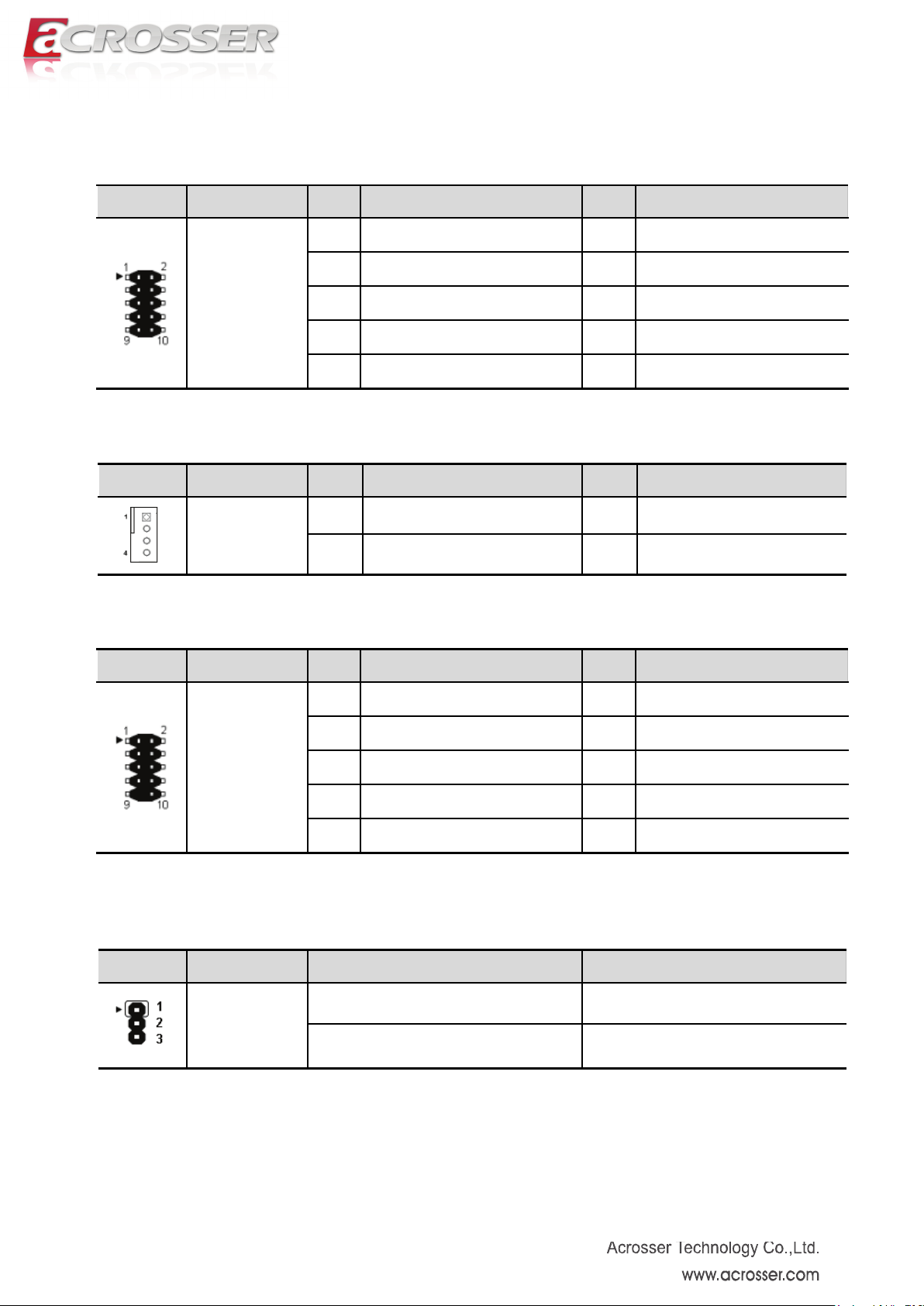
[7] Audio Header(5*2 Pin 2.54 mm)
Location Header Pin Definition Pin Definition
1 FRONT_MIC_L 2 GND
3 FRONT_MIC_R 4 + 3.3 V
F_AUDIO1
5 FRONT_OUT_R 6 GND
7 RRONT_Jack Detect
9 FRONT_OUT_L 10 GND
[8] CPU Fan Connector (4*1 Pin 2.54 mm)
Location Connector Pin Definition Pin Definition
1 GND 2 +12V
CPU_FAN
3 FAN TAC 4 FAN PW M
[9] Front USB Headers (5*2 Pin 2.54mm)
Location Header Pin Definition Pin Definition
1 + 5V 2 + 5V
3 USB0- 4 USB1-
F_USB1
F_USB2
5 USB0+ 6 USB1+
7 GND 8 GND
10 N/C
Note. It can not use USB Hub with power adaptor that connects to USB port.
[10] CMOS Clear Jumper (3*1 Pin 2.54mm)
Location Jumper Setting Function
1-2(Default) Normal
JCMOS1
2-3 Clear CMOS
Page 13

13
[11] LVDS VDD selection Jumper(3*2 Pin 2.54 mm)
Locatio
Jumper Setting Function
n
1-3 VDD=12V
LVDS_P1
3-5 VDD=3.3V
2-4 or 4-6 VDD=5V
[12] LVDS Signal Header(15*2 Pin 2.00 mm)
Location Header Pin Definition Pin Definition
1
3
VDD*
VDD*
2
VDD*
4 N/C
5 GND 6 GND
7 DA1- 8 DA1+
9 DA2- 10 DA2+
11 DA3- 12 DA3+
13 GND 14 GND
LVDS1
15 CLKA- 16 CLKA+
17 DA4- 18 DA4+
19 DB1- 20 DB1+
21 DB2- 22 DB2+
23 DB3- 24 DB3+
25 GND 26 GND
27 CLKB- 28 CLKB+
29 DB4- 30 DB4+
*VDD depends on the setting of LVDS_P1 jumper (Location 11).
[13] LVDS Backlight Control Header(5*1 Pin 2.00 mm)
Location Header Pin Definition Pin Definition
1 + 12V 2 GND
LVDS_P2
3 LVDS_EN_BKL 4 N/C
5 + 5V
Page 14

14
[14] RS485 Header (COM3, 3*1 Pin 2.54mm)
Location Header Pin Definition Pin Definition
1 RS485- 2 GND
J_1
3 RS485+
[15] COM7-10Headers(20*2 Pin 2.00 mm)
Location Header Pin Definition Pin Definition
1 COM7_DCD 2 COM7_RXD
3 COM7_TXD 4 COM7_DTR
5 GND 6 COM7_DSR
J_COM7-10
7 COM7_RTS 8 COM7_CTS
9 COM7_RI 10 GND
11 COM8_DCD 12 COM8_RXD
13 COM8_TXD 14 COM8_DTR
15 GND 16 COM8_DSR
17 COM8_RTS 18 COM8_CTS
19 COM8_RI
21 COM9_DCD 22 COM9_RXD
23 COM9_TXD 24 COM9_DTR
25 GND 26 COM9_DSR
27 COM9_RTS 28 COM9_CTS
29 COM9_RI 30 GND
31 COM10_DCD 32 COM10_RXD
33 COM10_TXD 34 COM10_DTR
35 GND 36 COM10_DSR
37 COM10_RTS 38 COM10_CTS
39 COM10_RI 40 GND
Page 15

15
Chapter 3 BIOS Settings
This chapter describes the BIOS menu displays and explains how to perform
common tasks needed to get the system up and running. It also gives detailed
explanation of the elements found in each of the BIOS menus. The following topics are
covered:
Main Setup
Advanced Setup
Chipset Setup
Boot Setup
Security Setup
Save & Exit Setup
Page 16

16
3.1. Main Setup
Once you enter the AMI Setup Utility, the Main menu will appear on the screen. Use
the arrow keys to highlight the item and then use the < + > < - > keys to select the
value you want in each item.
Note: Listed at the bottom of the menu are the control keys. If you need any help with
the item fields, you can press the <F1> key, and it will display the relevant information.
Option Choice Description
Model Name
Build Date & Time
System Language
N/A
N/A This item displays the date and time of building BIOS.
N/A This item select system default language.
This item displays the motherboard model name and
version.
Page 17

17
System Date
System Time
Access Level
N/A Set the date. Use Tab to switch between Date elements.
N/A Set the time. Use Tab to switch between Time elements.
N/A This item displays the level of users.
Page 18

18
3.2. Advanced Setup
Option Choice Description
ACPI Settings
Power On
LVDS Configuration
CPU Configuration
S AT A Configuration
Super I/O
Hardware Monitor
N/A This item display system ACPI parameters.
N/A This item display system power on settings after power fail.
N/A This item display LVDS panel parameters.
N/A This item displays the CPU configuration parameters.
N/A This item displays the SATA devices configuration.
N/A This item displays the system super I/O chip configuration.
N/A This item displays hardware monitor information.
COM7/8/9/10
N/A This item display COM7/8/9/10 parameters.
Configuration
Page 19

19
3.2.1. ACPI Settings Setup
Option Choice Description
ACPI Auto
Configuration
Enable Hibernation
ACPI Sleep State
Disabled,
Enables or disables BIOS ACPI Configuration.
Enabled
Disabled,
Enables or disables Hibernation mode.
Enabled
Disabled,
Set ACPI sleep state is disabled or S1 mode only.
S1only
Page 20

20
3.2.2. Power On Setup
Option Choice Description
PowerOn after
PowerFail
Power On, Power
Off, Last Status
This item defines the AC power state when power is
re-applied after a power failure.
Page 21

21
3.2.3. LVDS Configuration Setup
Page 22

22
3.2.4. CPU Configuration Setup
It display the CPU configuration information.
Page 23

23
3.2.5. SATA Configuration Setup
Option Choice Description
SATA Controller
SATA Mode
Selection
Serial ATA Port 1/2
Enabled, Disabled Enable or disable support for SATA device.
IDE This item defines the configuration of SATA controller
N/A This item displays the SATA port 1/2 device.
Page 24

24
3.2.6. Super I/O Setup
Option Choice Description
Super I/O Chip
COM1 ~ COM6
LPT
N/A This item displays the Super I/O model name.
N/A This item displays the COM1 ~ COM6 parameters.
N/A This item displays the LPT parameters.
Page 25

25
3.2.6.1. COM1 ~ COM6 Setup
Option Choice Description
Serial Port
Device Setting
Change Settings
Enabled, Disabled Enable or disable support for COM1~COM6
N/A This item displays the IO address and IRQ of COM1~COM6
Auto, other settings This item selects IO port and IRQ parameters.
Page 26

26
1.9 Mode,
3.2.6.2. LPT Setup
Option Choice Description
Parallel Port
Device Settings
Change Settings
Device Mode
Enabled, Disabled Enabled or disabled the support of LPT port
N/A
Auto, other settings This item select IO port and IRQ parameters.
STD Printer Mode, SPP Mode,
EPP-1.9 and SPP Mode,
EPP-1.7 and SPP Mode, ECP
Mode, ECP and EPP
ECP and EPP 1.7 Mode
This item displays the IO address and IRQ of
LPT port
Change the LPT port mode.
Page 27

27
3.2.7. Hardware Monitor Setup
Remark: After you clear CMOS info, please load optimized default CMOS setting and
reboot your system.
Page 28

28
3.2.8. COM7/8/9/10 Configuration Setup
Option Choice Description
Super I/O Chip
COM7 ~ COM10
N/A This item displays the Super I/O model name.
N/A This item displays the COM7 ~ COM10 parameters.
Page 29

29
3.2.8.1. COM7~COM10 Setup
Option Choice Description
Serial Port
Device Setting
Change Settings
Enabled, Disabled Enable or disable support for COM7~COM10
N/A This item displays the IO address and IRQ of COM7~COM10
Auto, other settings This item selects IO port and IRQ parameters.
Page 30

30
3.3. Chipset Setup
Option Choice Description
PCH-IO Configuration
System Agent
Configuration
N/A This item displays the PCH parameters.
N/A This item displays the System Agent parameters.
Page 31

31
3.3.1 PCH-IO Configuration Setup
Page 32

32
3.3.1.1. PCI Express Configuration Setup
Option Choice Description
PCI Express Port 1
PCI Express Port 2
PCI Express Port 3
N/A This item displays the PCI Express Port 1 parameter.
N/A This item displays the PCI Express Port 2 parameter.
N/A This item displays the PCI Express Port 3 parameter.
Page 33

33
Option Choice Description
PCI Express Port 1
ASPM Support
Enabled, Disabled Enabled or disabled the PCI Express Port 1
Set the ASPM Level:
Disabled, Force L0,
Auto
Force L0s - Force all links to L0s State
AUTO - BIOS auto configure
DISABLED - Disable ASPM
Page 34

34
3.3.1.2. USB Configuration Setup
Option Choice Description
EHCI1
EHCI2
Enabled, Disabled Enabled or disabled the EHCI Port 1
Enabled, Disabled Enabled or disabled the EHCI Port 2
Page 35

35
3.3.1.3. PCH Azalia Configuration Setup
Option Choice Description
Azalia
Enabled, Disabled,
Auto
Enabled or disabled the Azalia controller.
Page 36

36
3.3.2. System Agent Configuration Setup
Option Choice Description
Graphics
Configuration
Memory
Configuration
N/A This item displays the graphics parameter.
N/A This item displays the memory parameter.
Page 37

37
Select DVMT 5.0 Total Graphics Memory size
3.3.2.1. Graphics Configuration Setup
Option Choice Description
Primary Display
GTT Size
Aperture Size
DVMT Pre-Allocated
DVMT Total Gfx Mem
Select which of IGFX/PEG/PCI Graphics
Auto / IGFX / PEG
1MB / 2MB Select the GTT Size
128MB / 256MB / 512MB Select the Aperture Size
32M / 64M / 96M / 128M /
160M / 192M / 224M / 256M /
288M / 320M / 352M / 384M /
416M / 448M / 480M / 512M /
1024M
128M / 256M / MAX
device should be Primary Display 0r select
SG for Switchable Gfx.
Select DVMT 5.0 Pre-Allocated (Fixed)
Graphics Memory size used by the Internal
Graphics Device.
used by the Internal Graphics Device.
Page 38

38
3.3.2.2. Memory Configuration Setup
Page 39

39
3.4. Boot Setup
Option Choice Description
Bootup NumLock
State
Full Screen Logo
Fast Boot
On, Off Select the Keyboard NumLock state.
Enabled, Disabled Enabled or disabled the fullscreen logo support.
Enables or disables boot with initialization of a minimal
Disabled / Enabled
set of devices required to launch active boot option.
Page 40

40
3.5. Security Setup
Option Choice Description
Administrator
Password
User Password
Secure Boot
Secure Boot Mode
N/A Set the administrator password
N/A Set the user password
Secure Boot flow control. Secure Boot is possible only if
Enabled, Disabled
System runs in User Mode. Default is enabled.
Standard, Custom Select Secure Boot mode.
Page 41

41
Discard Changes and
3.6. Save & Exit Setup
option Choice Description
Save Changes and
Exit
Exit
Save Changes and
Reset
Pressing <Enter> on this item for
save changes and exit.
Pressing <Enter> on this item for
discard changes and exit.
Pressing <Enter> on this item for
confirmation : save configuration
and reset
Exit system setup after saving the changes.
Exit system setup without saving any changes.
Reset the system after saving the changes.
Page 42

42
Discard Changes and
Pressing <Enter> on this item for
Reset
Save Changes
Discard Changes
Restore Defaults
confirmation:
Pressing <Enter> on this item for
confirmation:
Pressing <Enter> on this item for
confirmation:
previous change values
Pressing <Enter> on this item for
confirmation:
system default values
Pressing <Enter> on this item for
reset without save
changes
save previous
change values
without save
load previous
Reset system setup without saving any changes.
Save Changes done so far to any of the setup
options.
Discard Changes done so far to any of the setup
options.
Restore/Load Default values for all the setup
options.
Save as User Defaults
Restore User Defaults
confirmation:
Pressing <Enter> on this item for
confirmation:
save changes as
user defaults
load user default
configuration
Save the changes done so far as User Defaults.
Restore the User Defaults to all the setup options.
Page 43

43
VGA2 (blue color)
FAQ
Does my system support Fedora and Linux basic?
The system has been verified with Fedora 17 and Linux basic. When you install OS, please plug your
monitor into VGA2 connector.
Page 44

44
Acrosser service contact info:
We deeply appreciate you purchase Acrosser products. If you have any questions or problems about
Acrosser products, the following is the suggested procedures: We will answer your questions a.s.a.p.
1) Describe your info and Acrosser system info
A. Your company name: _____________
B. Your contact info: ____________________ & phone number: _________________
C. Yo u r e-mail address: ______________________
D. Your company address: ___________________________________________
__________________________________________
E. Acrosser model name: _____________________
F. Acrosser Serial Number: _____________________
2) Describe system configuration
A. CPU type ________________
B. Memory size ___________________
C. Storage (e.g. HDD or CF or SSD) ___________________
D. Extra peripherals (e.g. graphic card) __________________________
E. Operating system & version (e.g. Windows 7 embedded) ____________________
F. Special API or driver ____________________ (If yes, please provide it for debug, thank
you.)
G. Running applications _____________________
H. Other _________________________
3) Describe your problems or questions:
4) Send the above info to one of the following Acrosser contact windows:
A. Acrosser local Sales Rep
B. Acrosser authorized channels
C. Acrosser e-mail window --- http://www.acrosser.com/inquiry.html
D. Acrosser FAX number --- 886-2-29992887
Page 45

45
Acrosser Headquarters
新北市三重區重新路五段609巷12號10樓
10F., No.12, Lane 609, Sec. 5, Chongsin Rd., Sanchong District, New Taipei City 241, Taiwan, R.O.C.
TEL: +886-(0)2-2 9999 000
FAX: +886-(0)2-2999-2887
Acrosser Taichung Office
台中市南屯區河南路四段162號12樓之6
12-6, No.162, Sec. 4, Henan Rd., Nantun Dist., Taichung City 408, Taiwan R.O.C.
TEL: +886-(0)4-2251-0659
FAX: +886-(0)4-2254-6079
Acrosser China Subsidiary
欣扬通电子有限公司 深圳分公司
深圳市福田区车公庙泰然九路21号 皇冠科技园3栋2楼东面A区 (邮编:518040)
A East 2F 3th Building, Crown Estate No.21, 9 Tai-Ran Road, Che Gong Miao, Futian Dist, Shenzhen,
China (Postal:518040)
TEL :+86-0755-83542210/2230/2240/2250/2260
FAX :+86-0755-83700087
Acrosser Shanghai Office
欣扬通电子有限公司 上海分公司
上海市徐汇区零陵路631号爱乐大厦12E (邮编:200085)
12E, Aile Building, No.631, Ling-ling Road, Xu-hui Dist, Shanghai, China (Postal:200085)
TEL :+86-021-64288853
FAX :+86-021-64288854
Acrosser Beijing Office
欣扬通电子有限公司 北京分公司
北京市海淀区安宁庄西三条9号宜品上层2-703(邮编:100085)
Room 2-703,Yipinshangceng,No.9,Xisantiao,Anning Zhuang,Haidian Dist,Beijing (Postal:100085)
TEL :+86-010-82359009
FAX :+86-010-82359003
Acrosser USA Subsidiary
11235 Knott Ave. Suite A, Cypress, CA 90630, USA
Toll Free: +1-866-401-9463
TEL: +1-714-903-1760
FAX: +1-714-903-5629
info@acrosserusa.com
 Loading...