

Page 1

1
AMB-D255T3 Board
User Manual
Page 2

2
Copyright
All Rights Reserved.
Manual’s first edition:
For the purpose of improving reliability, design and function, the information in this
document is subject to change without prior notice and does not represent a
commitment on the part of the manufacturer.
In no event will the manufacturer be liable for direct, indirect, special, incidental, or
consequential damages arising out of the use or inability to use the product or
documentation, even if advised of the possibility of such damages.
This document contains proprietary information protected by copyright. All rights
are reserved. No part of this manual may be reproduced by any mechanical, electronic,
or other means in any form without prior written permission of the manufacturer.
Trademarks
AMB-D255T3 is a registered trademark of Acrosser; IBM PC is a registered
trademark of the International Business Machines Corporation; Atom is a registered
trademark of Intel Technologies Inc; AMI is a registered trademark of America
Megatrends Inc; other product names mentioned herein are used for identification
purposes only and may be trademarks and/or registered trademarks of their respective
companies.
Page 3

3
Table of Contents
Chapter 1 Introduction .......................................................................... 4
1.1. Specifications ............................................................................................................ 4
1.2. Package Contents ...................................................................................................... 5
Chapter 2 H/W Information .................................................................. 6
2.1. Mainboard illustration ............................................................................................... 6
2.2. Headers and Jumper Settings .................................................................................... 7
Chapter 3 BIOS Settings ..................................................................... 14
3.1. Main Setup .............................................................................................................. 15
3.2. Advanced Setup ....................................................................................................... 17
3.2.1. Power On Setup ............................................................................................... 18
3.2.2. CPU Configuration Setup ................................................................................ 19
3.2.3. IDE Configuration Setup ................................................................................. 21
3.2.4. USB Configuration Setup ................................................................................ 22
3.2.5. Super I/O Setup ............................................................................................... 23
3.3. Chipset Setup ........................................................................................................... 32
3.3.1 Host Bridge Setup ............................................................................................ 33
3.3.2. South Bridge Setup .......................................................................................... 35
3.4. Boot Setup .................................................................................................................. 41
3.5. Security Setup ............................................................................................................. 42
3.6. Save & Exit Setup ...................................................................................................... 43
Page 4

4
CPU
Intel Atom D2550
Dual-core, clock speed 1.86G,TDP 10W
Chipset
Intel NM10,TDP 2.1 W
Display
1 * VGA
1 * HDMI
1 * Single Channel 18-bit LVDS
Memory
Support DDR3 1066MHz
1 * 204-pin SO-DIMM slot,Up to 4 GB
Storage
Intel Serial ATA2 (3 Gbps) controller
2 * Serial ATA ports
Ethernet
2 * Realtek 8111E PCI-E 1000Mbps LAN
Serial
6 * RS232 (COM6 only TX/RX support)
Other Ports
6 * USB2.0 (4 * Rear I/O + 2 * Pin Header)
8 * GPIO
1 * PCIe x1
1 * Mini PCIe (Wireless Devices are Supported)
Temperature
Operating: 0~55℃
BIOS
AMI UEFI BIOS
OS Support
Windows 7 32-bit, Fedora 14 32-bit
Form Factor
Mini ITX
Chapter 1 Introduction
AMB-D255T3 Series with Intel Atom D2550 processor is a multi-function Industrial
Main-board, which is suitable for using in all kind of applications. Besides it basic I/O
ports like VGA, USB, COM. LAN, and GPIO.
1.1. Specifications
Page 5

5
1.2. Package Contents
Check if the following items are included in the package.
1 x AMB-D255T3
1 x Quick Manual
1 x Driver CD
6 x COM Cable
1 x SATA Cable
1 x IO Shield
Page 6

6
DIMM1
204-Pin DDR3 SO-DIMM Socket
PCH
Intel NM10 Chipset
CPU
Intel ATOM D2550 CPU
MINIPCIE1
Mini PCI-Express Slot
Chapter 2 H/W Information
This chapter describes the installation of AMB-D255T3. At first, it shows the
Function diagram and the layout of AMB-D255T3. It then describes the unpacking
information which you should read carefully, as well as the jumper/switch settings
for the AMB-D255T3 configuration.
2.1. Mainboard illustration
Page 7

7
2.2. Headers and Jumper Settings
Page 8

8
Location
Header
Pin
Definition
Pin
Definition
J_COM1
1
J6 *
2
RXD
3
TXD
4
DTR
5
GND
6
DSR 7 RTS
8
CTS
9
RI
10
J_COM2
1
J7 *
2
RXD 3 TXD
4
DTR
5
GND
6
DSR
7
RTS
8
CTS
KBMS1
PS/2 Keyboard and Mouse connector
J15
COM6 control jumper
F_USB1
Front USB1 pin header
J_COM1
COM1 pin header
SYS_FAN1
System FAN connector.
PCI1
PCI slot
J_COM2
COM2 pin header
CPU_FAN1
CPU FAN connector
J12 (Reserved)
COM3 control jumper
J_COM3
COM3 pin header
LVDS_P1
LVDS backlight control pin header
J11 (Reserved)
COM3 control jumper
J_COM4
COM4 pin header
ATX1
ATX power supply connector
AUDIO1
Audio connector
J_COM5
COM5 pin header
LVDS1
LVDS pin header
USB2_RJ1
USB2 and LAN1 connector
J_COM6
COM6 pin header
SATA2
SATA2 connector
USB2_RJ2
USB2 and LAN2 connector
J6
COM1 control jumper
SATA1
SATA1 connector
VGA1
VGA connector
J7
COM2 control jumper
LVDS_P2
LVDS VCC selection jumper
LPT1
LPT connector
J10
COM3 control jumper
J_GPIO1
GPIO pin header
HDMI1
HDMI connector
J13
COM4 control jumper
JCMOS1
Clear CMOS jumper
J14
COM5 control jumper
F_PANEL1
Front panel pin header
Note. AMB-D255T3 doesn’t design SATA power connector on the board. Please
use the power supply with SATA power connector for SATA device.
2 ~ 7. COM1~6 Headers(5*2 Pin 2.00mm)
Page 9

9
9
J7 *
10
J_COM3
1
J10 *
2
RXD 3 TXD
4
DTR
5
GND
6
DSR 7 RTS
8
CTS
9
N/C
[1]
J_COM4
1
J13 *
2
RXD
3
TXD
4
DTR
5
GND
6
DSR 7 RTS
8
CTS
9
N/C
[1]
J_COM5
1
J14 *
2
RXD 3 TXD
4
N/C 5 GND
6
N/C 7 RTS
8
CTS
9
N/C
[1]
J_COM6
1
J15 *
2
RXD
3
TXD
4
N/C 5 GND
6
N/C
7
N/C
8
N/C
9
N/C
[1]
10
Location
Jumper
Setting
Function
J6
1-2
Pin1: + 5V
3-4(Default)
Pin1: DCD
5-6
Pin1: + 12V
Notes. These signals are depend on relevant Jumpers (e.g. Pin1 of J_COM1
depends on J6 Jumper), to find more details, check the following table (Location
8~13 & 27~28).
Notes. The pin9 is N/C or 5V or 12V selectable (need corresponding hardware
supported), and the default value is N/C.
8. COM1 Control Jumper(3*2 Pin 2.00mm)
Page 10

10
Location
Jumper
Setting
Function
J7
1-3(Default)
Pin1: DCD
3-5
Pin1: + 5V
2-4
Pin9: + 12V
4-6(Default)
Pin9: RI
Location
Jumper
Setting
Function
J10
1-2(Default)
Pin1: N/C
2-3
Pin1: + 5V
3-4
Pin1: + 12V
Location
Jumper
Setting
Function
J13
1-2(Default)
Pin 1: N/C
2-3
Pin 1: + 5V
3-4
Pin 1: + 12V
Location
Jumper
Setting
Function
J14
1-2(Default)
Pin 1: N/C
2-3
Pin 1: + 5V
3-4
Pin 1: + 12V
Location
Jumper
Setting
Function
J15
1-2(Default)
Pin 1: N/C
2-3
Pin 1: + 5V
3-4
Pin 1: + 12V
9. COM2 Control Jumper(3*2 Pin 2.00mm)
10. COM3 Control Jumpers(4*1 Pin 2.00mm)
11. COM4 Control Jumper(4*1 Pin 2.00mm)
12. COM5 Control Jumper(4*1 Pin 2.00mm)
13. COM6 Control Jumper(4*1 Pin 2.00mm)
Page 11

11
Location
Connector
Pin
Definition
Pin
Definition
SYS_FAN1
1
GND
2
+ 12V
3
N/C
Location
Connector
Pin
Definition
Pin
Definition
CPU_FAN1
1
GND
2
+ 12V
3
FAN Speed Detection
4
FAN Speed Control
Location
Header
Pin
Definition
Pin
Definition
LVDS_P1
1
+ 12V
2
GND
3
LVDS_BKL_EN
4
N/C
5
+ 5V
Location
Header
Pin
Definition
Pin
Definition
LVDS1
1
VCC
[1]
2
VCC
[1]
3
VCC
[1]
4
N/C
5
GND
6
GND
7
LVDS_A_DATA0-
8
LVDS_A_DATA0+
9
LVDS_A_DATA1-
10
LVDS_A_DATA1+
11
LVDS_A_DATA2-
12
LVDS_A_DATA2+
13
GND
14
GND
15
LVDS_A_CLK-
16
LVDS_A_CLK+
17
LVDS_A_DATA3-
18
LVDS_A_DATA3+
19
N/C
20
N/C
21
N/C
22
N/C
23
N/C
24
N/C
14. System Fan Connector(3*1 Pin 2.54mm)
15. CPU Fan Connector(4*1 Pin 2.54mm)
16. LVDS Backlight Control Header(5*1 Pin 2.00mm)
18. LVDS Header(15*2 Pin 2.00mm)
Page 12

12
25
GND
26
GND
27
N/C
28
N/C
29
N/C
30
N/C
Location
Jumper
Setting
Function
LVDS_P2
1-2(Default)
+ 3.3V
2-3
+ 5V
Location
Header
Pin
Definition
Pin
Definition
J_GPIO1
1
GPO6(0x50C Bit6)
2
GPI22(0x50E Bit6)
3
GPI12 (0x50D Bit4)
4
GPI38(0x538 Bit6)
5
GND
6
GPO7(0x50C Bit7)
7
GPO33(0x538 Bit1)
8
GPO36(0x538 Bit4)
9
GPI39(0x538 Bit7)
10
+ 5V *
Notes. VCC could be 3.3V (default) or 5V by setting the LVDS VCC Selection
Jumper (LVDS_P2, Location 21).
21. LVDS VCC Selection Jumper(3*2 Pin 2.54mm)
22. GPIO Header(5*2 Pin 2.00mm)
Note. The value is 3.3V or 5V selectable (need hardware supported), and the
default value is 5V.
Page 13

13
Location
Jumper
Setting
Function
JCMOS1
1-2(Default)
Normal
2-3
Clear CMOS
Location
Header
Pin
Definition
Pin
Definition
F_PANEL1
1
HD LED+
2
Power LED+
3
HD LED-
4
Power LED-
5
RESET-
6
PWR+
7
RESET+
8
PWR-
9
N/C
Location
Header
Pin
Definition
Pin
Definition
F_USB1
1
+ 5 V
2
+ 5 V
3
USB4-
4
USB5-
5
USB4+
6
USB5+
7
GND
8
GND
10
N/C
23. CMOS Clear Jumper(3*1 Pin 2.54mm)
24. Front Panel Header(5*2 Pin 2.54mm)
25. Front USB Headers(5*2 Pin 2.54mm)
Note. It can not use USB Hub with power adaptor that connects to USB port.
Page 14

14
Chapter 3 BIOS Settings
This chapter describes the BIOS menu displays and explains how to perform
common tasks needed to get the system up and running. It also gives detailed
explanation of the elements found in each of the BIOS menus. The following topics are
covered:
Main Setup
Advanced Setup
Chipset Setup
Boot Setup
Security Setup
Save & Exit Setup
Page 15
15
Option
Choice
Description
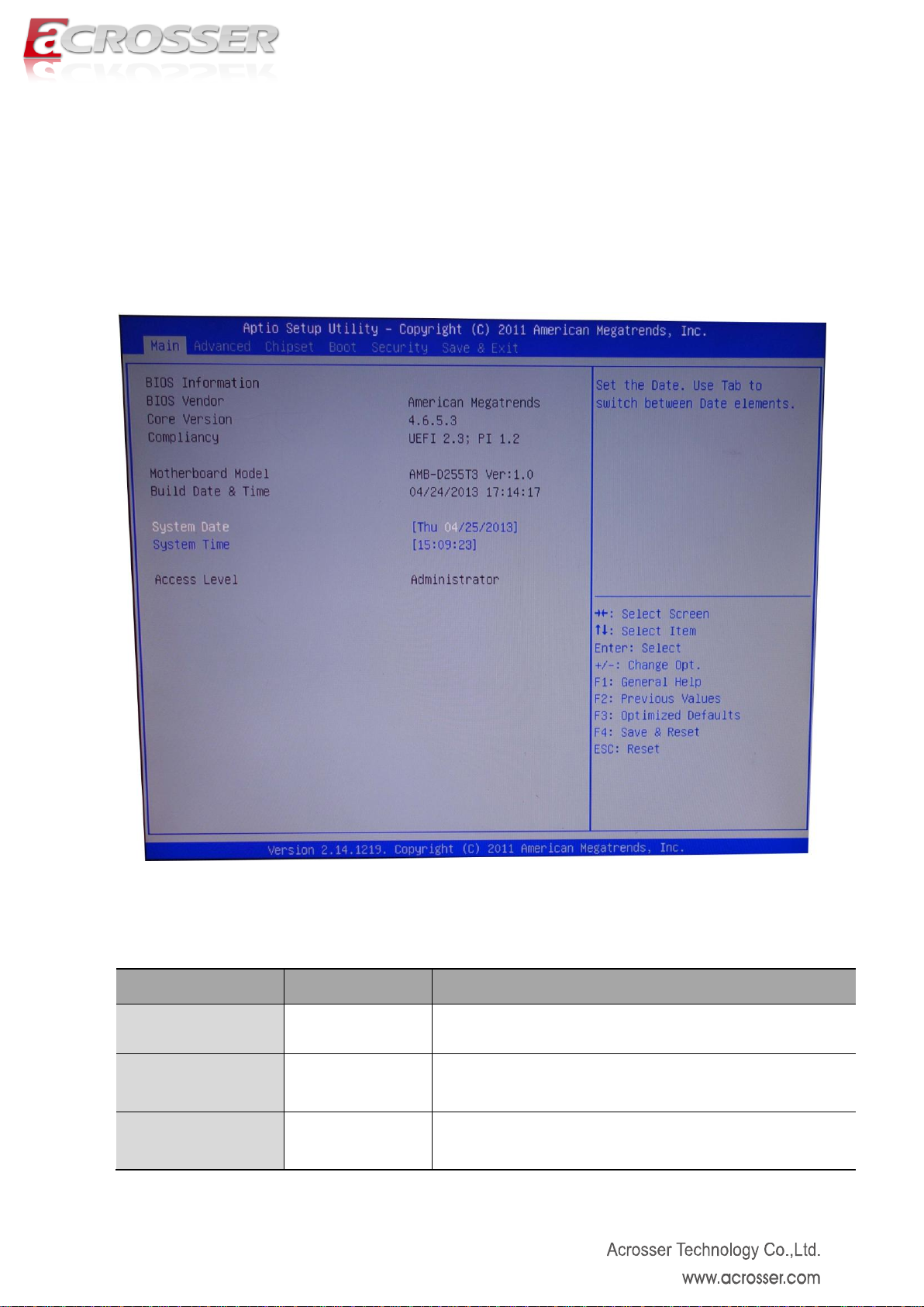
BIOS Vender
N/A
This item displays the BIOS vender’s brand name
Core Vision
N/A
This item displays the core version of BIOS
Compliancy
N/A
This item displays the compliancy of BIOS
3.1. Main Setup
Once you enter the AMI Setup Utility, the Main menu will appear on the screen. Use
the arrow keys to highlight the item and then use the <Pg Up> <Pg Dn> keys to select
the value you want in each item.
Note: Listed at the bottom of the menu are the control keys. If you need any help with
the item fields, you can press the <F1> key, and it will display the relevant information.
Page 16

16
Motherboard Model
N/A
This item displays the motherboard model name and
version
Build Date & Time
N/A
This item displays the date and time of building BIOS
System Date
N/A
Set the date. Use Tab to switch between Date elements
System Time
N/A
Set the time. Use Tab to switch between Time elements
Access Level
N/A
This item displays the level of users
Page 17
17
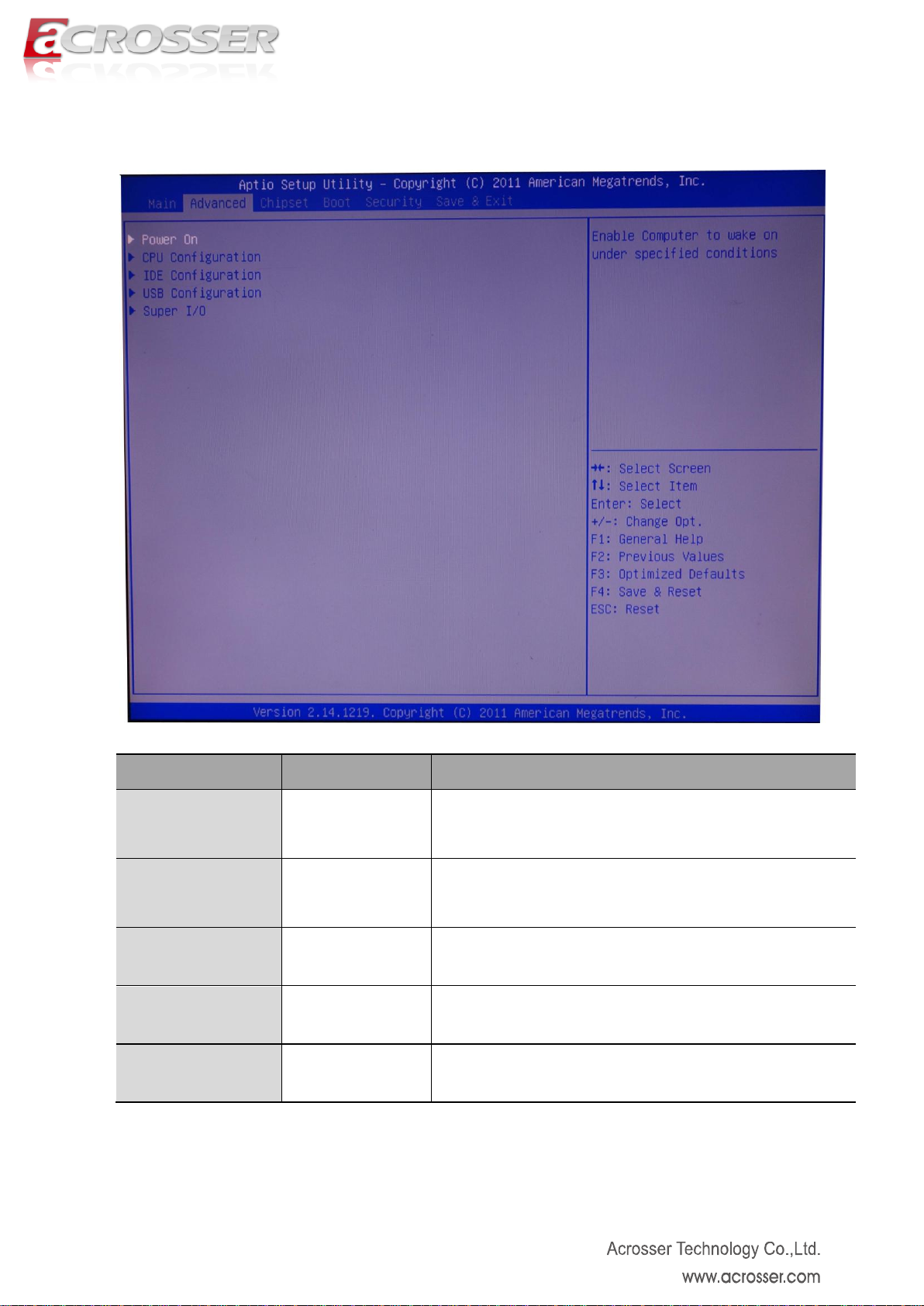
Option
Choice
Description
Power On
N/A
This item enable computer to wake on under specified
conditions.
CPU Configuration
N/A
This item displays the CPU configuration parameters.
IDE Configuration
N/A
This item displays the IDE devices configuration.
USB Configuration
N/A
This item displays the USB configuration parameters.
Super I/O
N/A
This item displays the system super I/O chip configuration
parameters.
3.2. Advanced Setup
Page 18
18
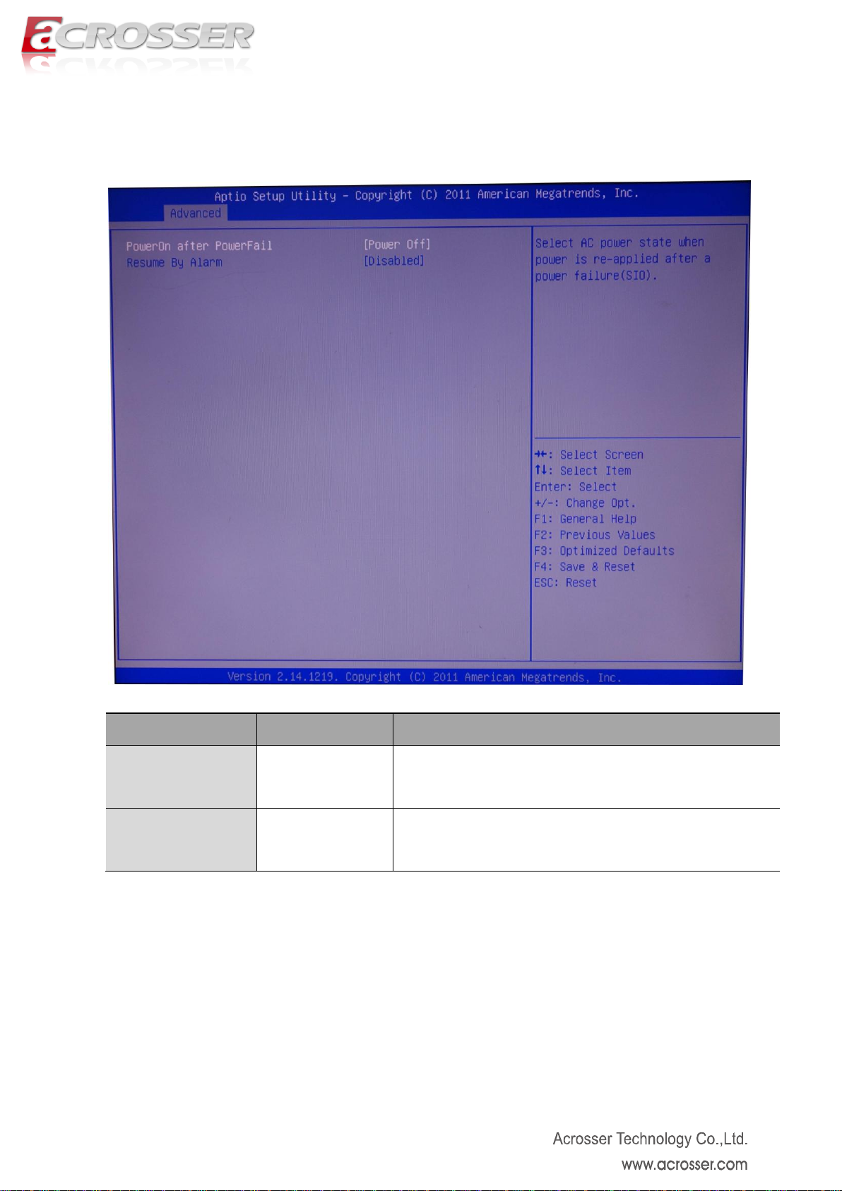
Option
Choice
Description
PowerOn after
PowerFail
Power On, Power
Fail, Last Status
This item defines the AC power state when power is
re-applied after a power failure.
Resume By Alarm
Disabled, Enabled
This item defines the computer will wake on by time setting.
3.2.1. Power On Setup
Page 19

19
Option
Choice
Description
Processor Type
N/A
This item displays the CPU type
EMT64
N/A
This item displays it can support EMT64.
Processor Speed
N/A
This item displays the CPU speed.
System Bus Speed
N/A
This item displays the System Bus speed.
Ratio Status
N/A
This item displays the ratio status.
Actual Ration
N/A
This item displays the actual ratio.
3.2.2. CPU Configuration Setup
Page 20

20
System Bus Speed
N/A
This item displays the System Bus speed.
Processor Stepping
N/A
This item displays the CPU stepping
Microcode Revision
N/A
This item displays the microcode revision
L1 Cache RAM
N/A
This item displays the L1 cache ram size.
L2 Cache RAM
N/A
This item displays the L2 cache ram size.
Processor Code
N/A
This item displays the CPU code quantity.
Hyper-Threading
N/A
This item displays the Hyper-Threading supported.
Page 21
21
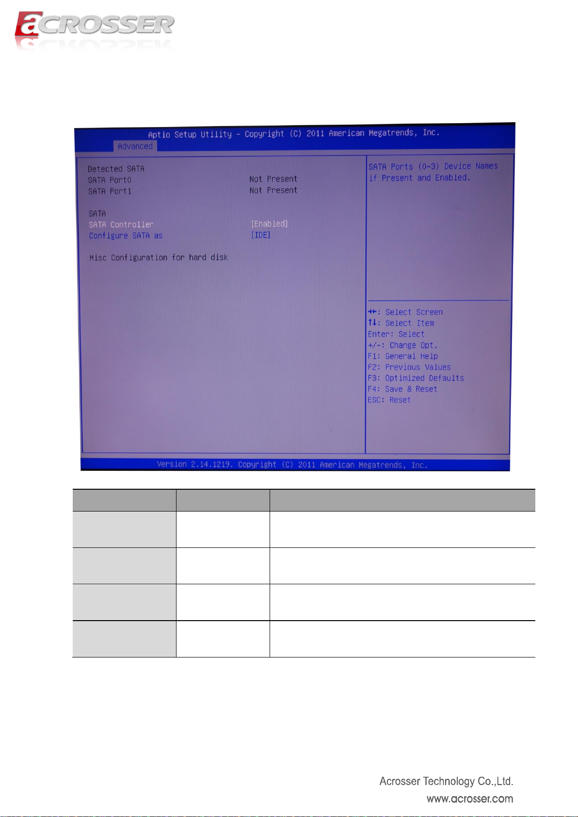
Option
Choice
Description
SATA Port0
N/A
This item displays the SATA port0 device.
SATA Port1
N/A
This item displays the SATA port1 device.
SATA Controller
Enabled, Disabled
Enable or disable support for SATA device.
Configure SATA as
IDE, AHCI
This item defines the configuration of SATA controller
3.2.3. IDE Configuration Setup
Page 22
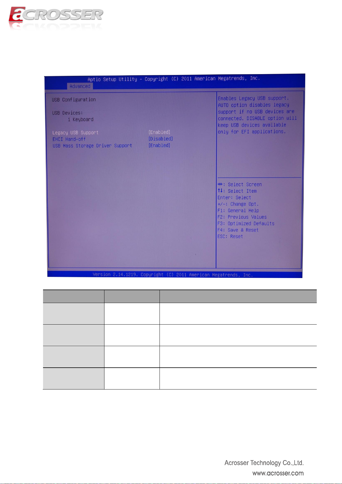
22
Option
Choice
Description
USB Device
N/A
This item displays the USB devices connected to system.
Legacy USB
Support
Enabled, Disabled,
Auto
Enable or disable support for legacy USB.
EHCI Hand-off
Enabled, Disabled
Enable or disable support for EHCI Hand-off.
USB Mass Storage
Driver Support
Enabled, Disabled
Enable or disable support for USB Mass Storage Driver.
3.2.4. USB Configuration Setup
Page 23

23
Option
Choice
Description
Super I/O Chip
N/A
This item displays the Super I/O model name.
COM1
N/A
This item displays the COM1 parameters.
COM2
N/A
This item displays the COM2 parameters.
COM3
N/A
This item displays the COM3 parameters.
COM4
N/A
This item displays the COM4 parameters.
COM5
N/A
This item displays the COM5 parameters.
3.2.5. Super I/O Setup
Page 24

24
COM6
N/A
This item displays the COM6 parameters.
LPT
N/A
This item displays the LPT parameters.
Page 25
25
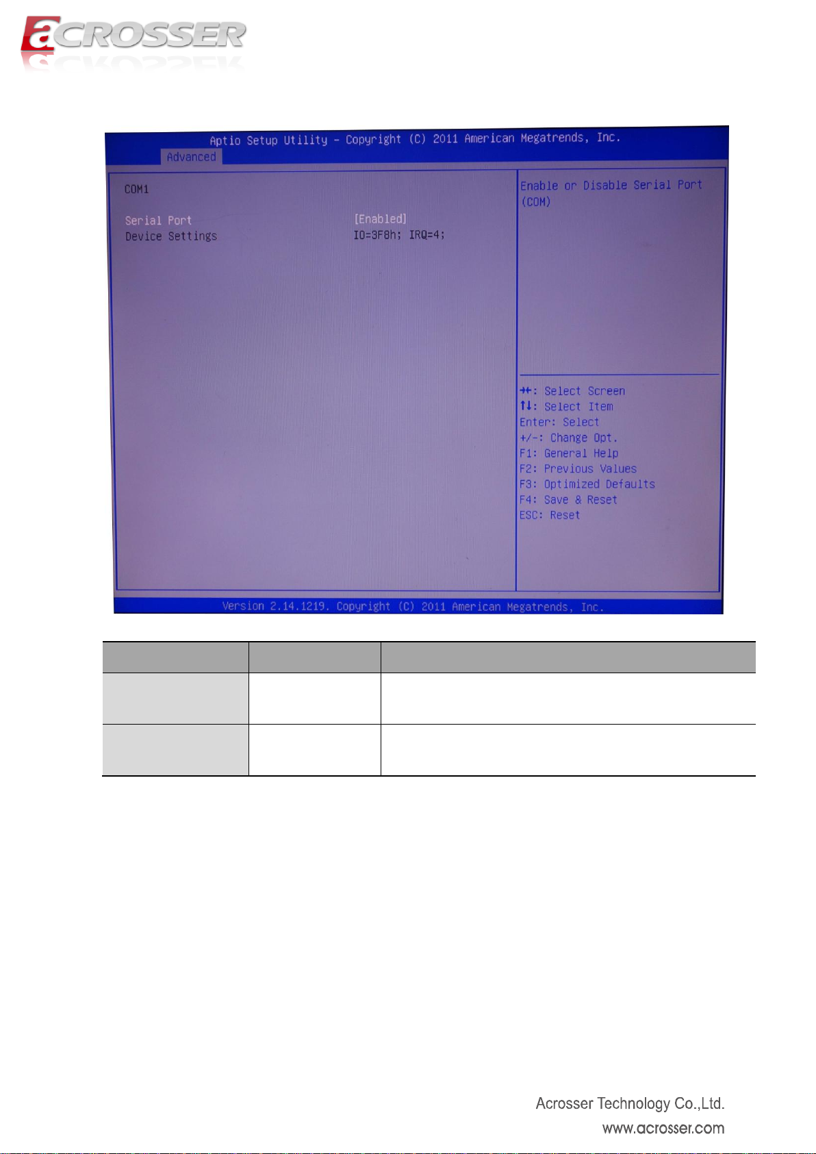
Option
Choice
Description
Serial Port
Enabled, Disabled
Enable or disable support for COM1
Device Setting
N/A
This item displays the IO address and IRQ of COM1
3.2.5.1. COM1 Setup
Page 26

26
Option
Choice
Description
Serial Port
Enabled, Disabled
Enable or disable support for COM2
Device Setting
N/A
This item displays the IO address and IRQ of COM2
3.2.5.2. COM2 Setup
Page 27
27
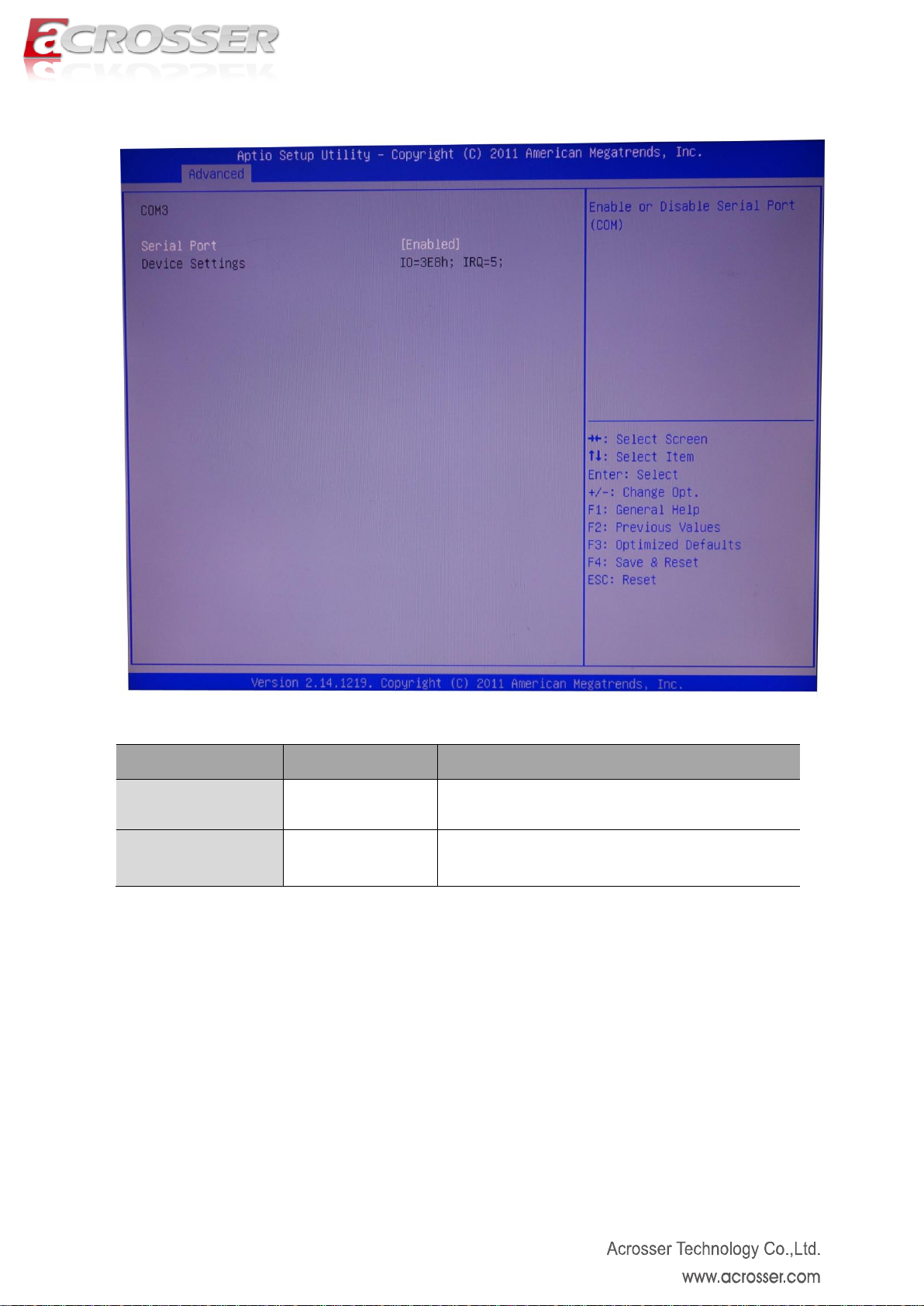
Option
Choice
Description
Serial Port
Enabled, Disabled
Enable or disable support for COM3
Device Setting
N/A
This item displays the IO address and IRQ of
COM3
3.2.5.3 COM3 Setup
Page 28

28
Option
Choice
Description
Serial Port
Enabled, Disabled
Enable or disable support for COM4
Device Setting
N/A
This item displays the IO address and IRQ of
COM4
3.2.5.4 COM4 Setup
Page 29

29
Option
Choice
Description
Serial Port
Enabled, Disabled
Enable or disable support for COM5
Device Setting
N/A
This item displays the IO address and IRQ of
COM5
3.2.5.5. COM5 Setup
Page 30

30
Option
Choice
Description
Serial Port
Enabled, Disabled
Enable or disable support for COM6
Device Setting
N/A
This item displays the IO address and IRQ of
COM6
3.2.5.6. COM6 Setup
Page 31
31
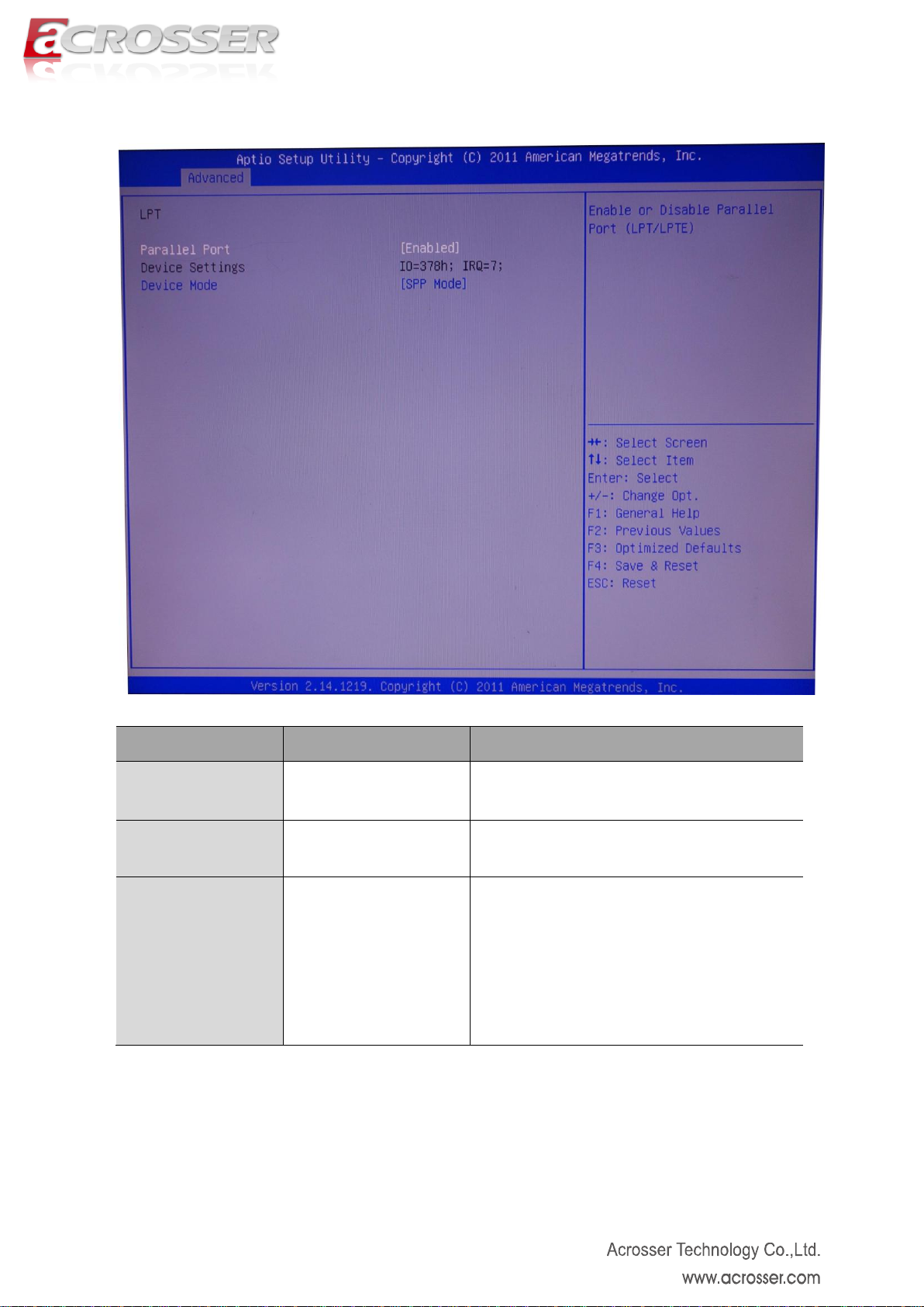
Option
Choice
Description
Parallel Port
Enabled, Disabled
Enabled or disabled the support of LPT port
Device Settings
N/A
This item displays the IO address and IRQ of
LPT port
Device Mode
STD Printer Mode, SPP
Mode, EPP-1.9 and SPP
Mode, EPP-1.7 and SPP
Mode, ECP Mode, ECP
and EPP 1.9 Mode, ECP
and EPP 1.7 Mode
Change the LPT port mode.
3.2.5.7. LPT Setup
Page 32
32
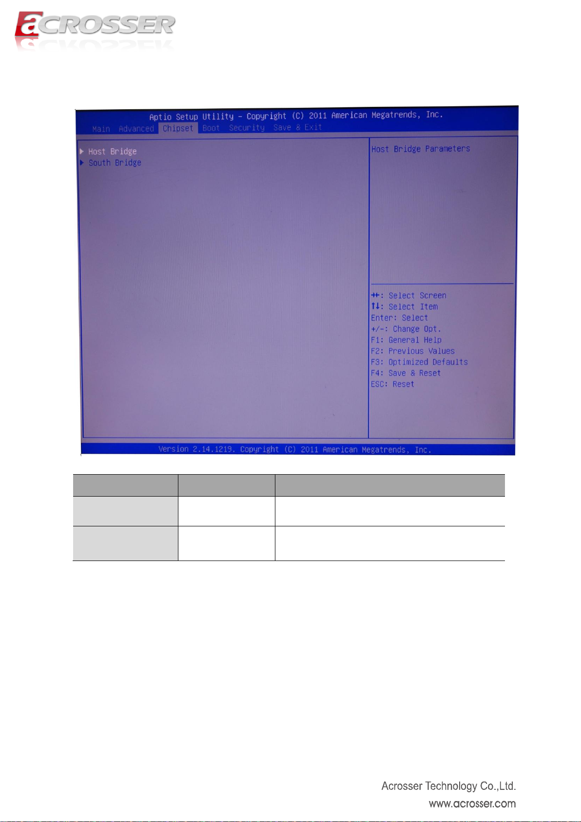
Option
Choice
Description
Host Bridge
N/A
This item displays the Host Bridge parameters.
South Bridge
N/A
This item displays the South Bridge parameters.
3.3. Chipset Setup
Page 33
33
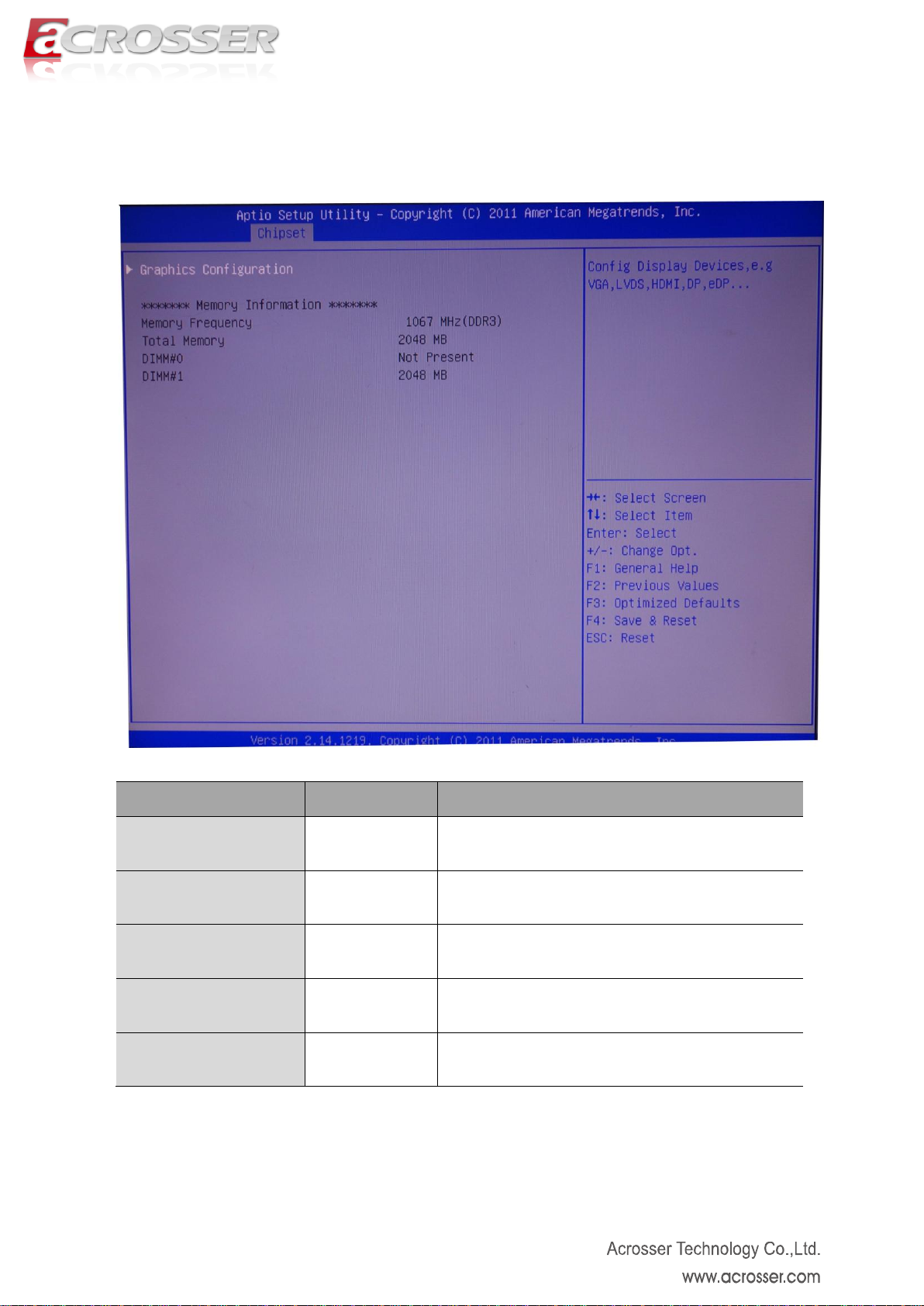
Option
Choice
Description
Graphic Configuration
N/A
This item sets the display device configuration.
Memory Frequency
N/A
This item displays the memory frequency.
Total Memory
N/A
This item displays the total memory size.
DIMM0
N/A
This item displays the memory of DIMM0.
DIMM1
N/A
This item displays the memory of DIMM1.
3.3.1 Host Bridge Setup
Page 34
34
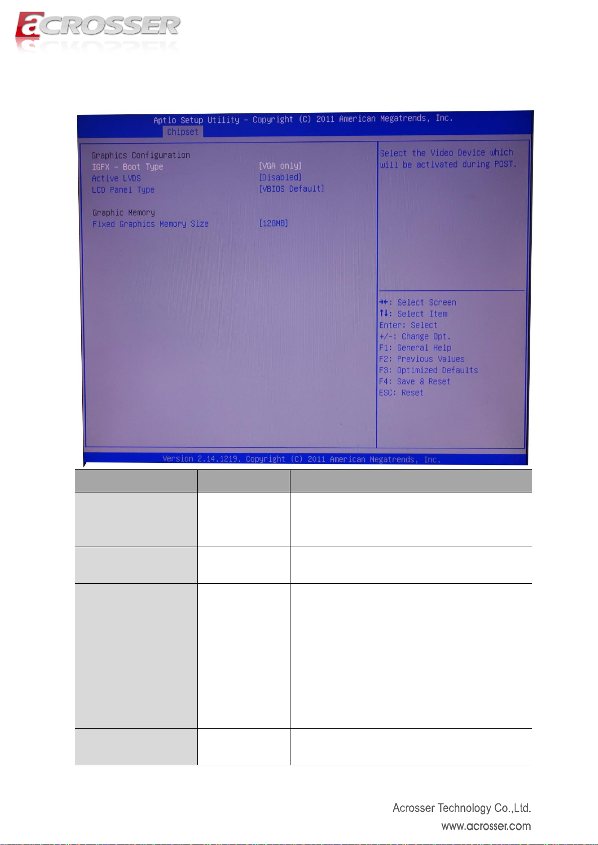
Option
Choice
Description
IGFX – Boot Type
VGA only,
LVDS only, HDMI
only,
Select the video device which will be activated during
POST.
Active LVDS
Disabled, Int-LVDS,
EDP
Select the way to active LVDS
LVDS Panel Type
VBIOS Default,
800x480 18bit,
800x600 18bit,
1024x600 18bit,
1024x768 18bit,
1366x768 18bit,
1280x800 18bit,
1440x900 18bit
Select the LVDS panel resolution
Fixed Graphic Memory
Size
128MB, 256MB
Select the fixed graphic memory size.
3.3.1.1. Graphic Configuration Setup
Page 35
35
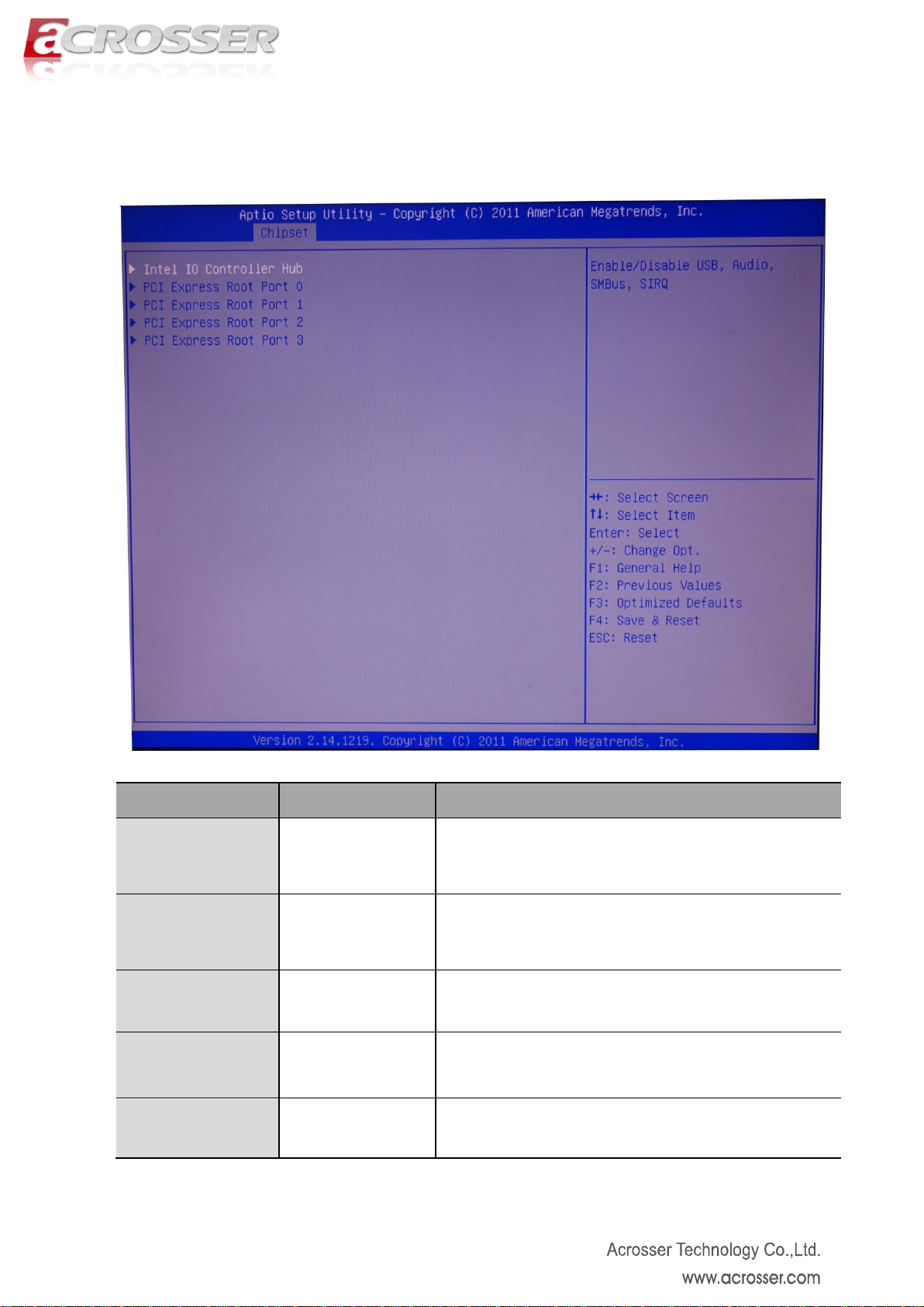
Option
Choice
Description
Intel IO Controller
Hub
N/A
This item displays the IO controller Hub parameter.
PCI Express Port0
N/A
This item displays the PCI Express Port0 parameter.
PCI Express Port1
N/A
This item displays the PCI Express Port1 parameter.
PCI Express Port2
N/A
This item displays the PCI Express Port2 parameter.
PCI Express Port3
N/A
This item displays the PCI Express Port3 parameter.
3.3.2. South Bridge Setup
Page 36
36
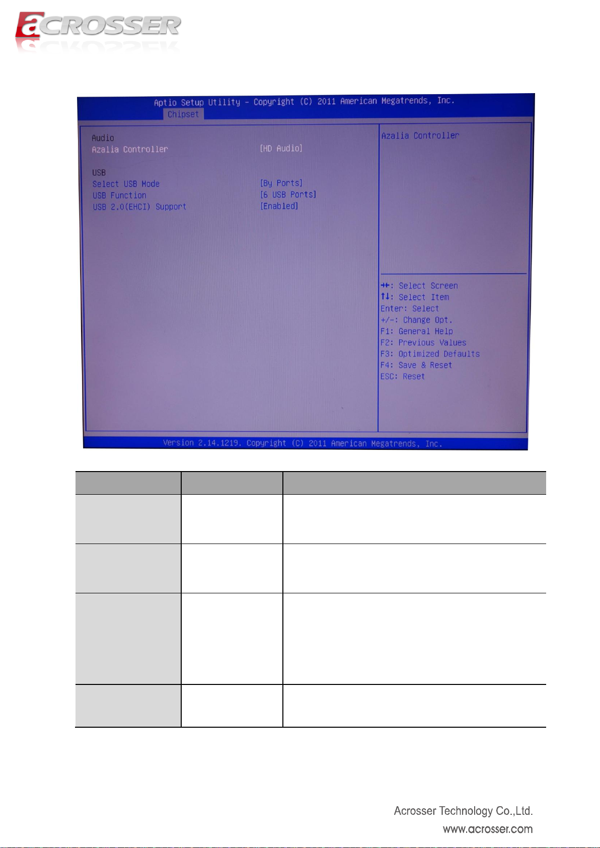
Option
Choice
Description
Azalia Controller
Disabled, HD Audio
Enabled or disabled the Azalia controller
Select USB Mode
By Ports, By
Controller
Select the USB mode to control USB ports
USB Function
Disabled, 1 USB
Ports, 2 USB Ports,
3 USB Ports, 4 USB
Ports, 5 USB Ports,
6 USB Ports
Select the numbers of USB ports
USB 2.0(EHCI)
Support
Enabled, Disabled
Enabled or disabled the USB 2.0(EHCI) support.
3.3.2.1. Intel IO Controller Hub Setup
Page 37
37
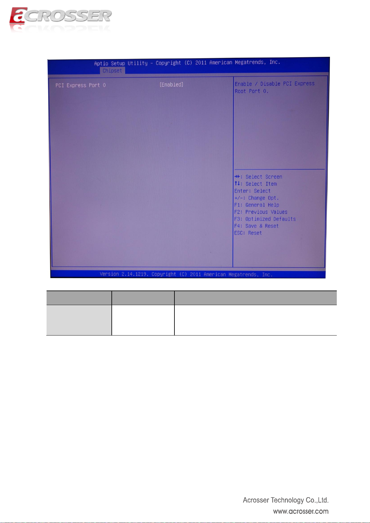
Option
Choice
Description
PCI Express Port 0
Enabled, Disabled
Enabled or disabled the PCI Express Port 0
3.3.2.2. PCI Express Port 0 Setup
Page 38
38
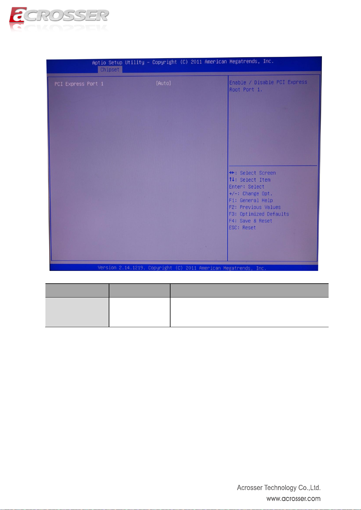
Option
Choice
Description
PCI Express Port 1
Enabled, Disabled,
Auto
Enabled or disabled the PCI Express Port 1
3.3.2.3. PCI Express Port 1 Setup
Page 39
39
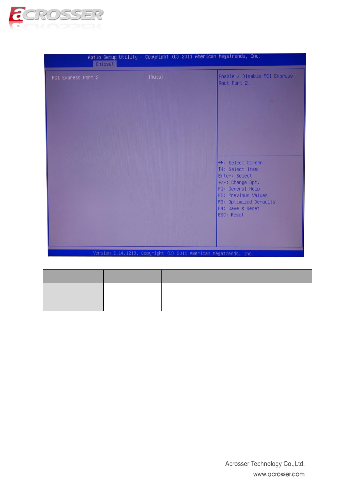
Option
Choice
Description
PCI Express Port 2
Enabled, Disabled,
Auto
Enabled or disabled the PCI Express Port 2
3.3.2.4. PCI Express Port 2 Setup
Page 40

40
Option
Choice
Description
PCI Express Port 3
Enabled, Disabled,
Auto
Enabled or disabled the PCI Express Port 3
3.3.2.5. PCI Express Port 3 Setup
Page 41
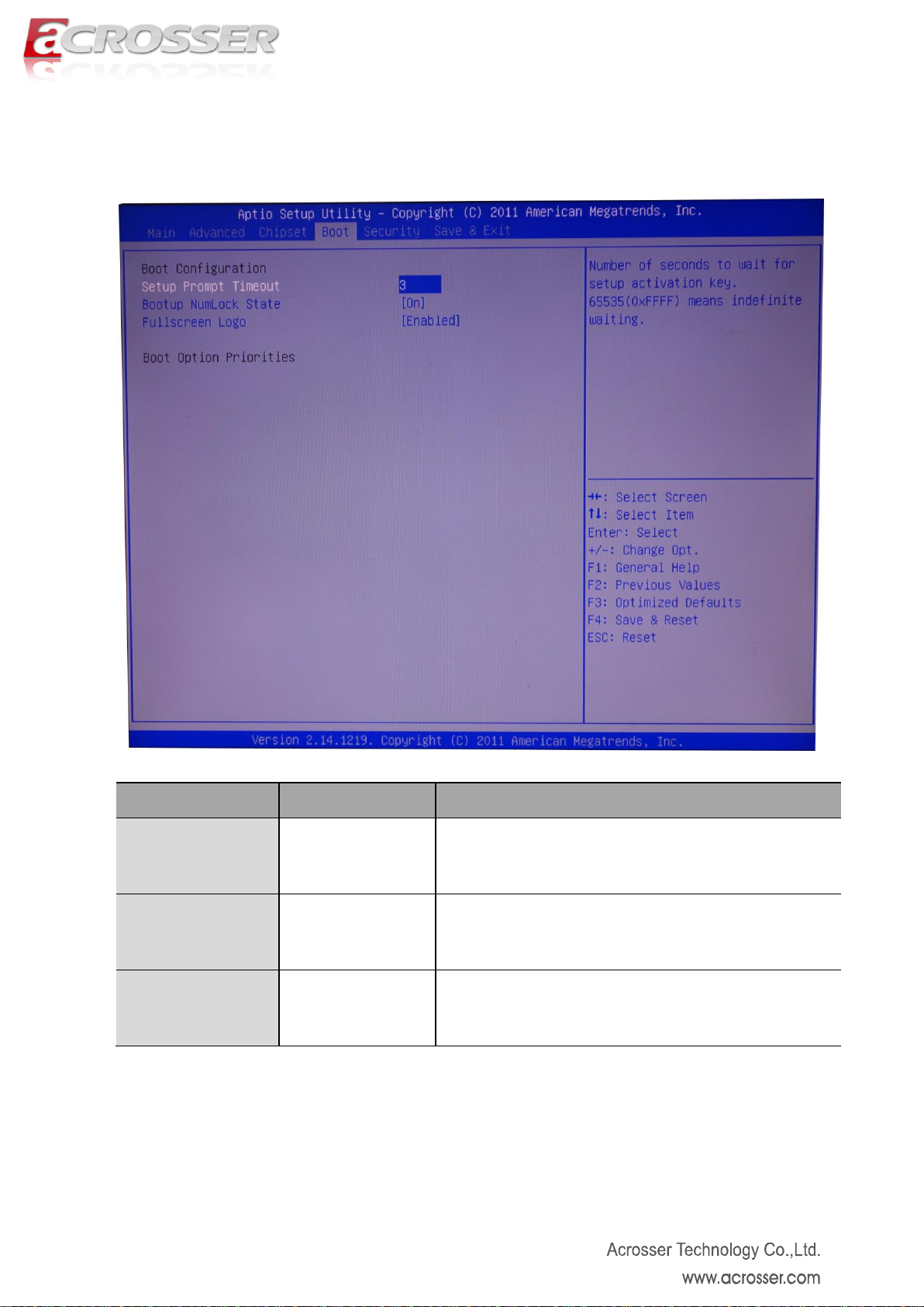
41
Option
Choice
Description
Setup Prompt
Timeout
N/A
Number of seconds to wait for setup activation key.
Bootup NumLock
State
On, Off
Select the Keyboard NumLock state.
Fullscreen Logo
Enabled, Disabled
Enabled or disabled the fullscreen logo support.
3.4. Boot Setup
Page 42

42
Option
Choice
Description
Administrator
Password
N/A
Set the administrator password
User Password
N/A
Set the user password
3.5. Security Setup
Page 43

43
Option
Choice
Description
Save and Reset
Yes, No
Reset the system after saving the changes.
Save Changes
Yes, No
Save changes done so far to any of the setup options.
Discard and Reset
Yes, No
Reset the system without saving any changes.
Discard Changes
Yes, No
Discard changes done so far to any of the setup options.
3.6. Save & Exit Setup
Page 44

44
Restore Defaults
Yes, No
Restore and load default settings for all the setup options.
Save as User
Defaults
Yes, No
Save changes done so far as user default.
Restore User
Defaults
Yes, No
Restore user default settings for all the setup options
 Loading...