

Page 1

1
AES-HM76Z1FL
System Manual
Page 2

2
Copyright
All Rights Reserved.
Manual’s first edition:
For the purpose of improving reliability, design and function, the information in this
document is subject to change without prior notice and does not represent a commitment on
the part of the manufacturer.
The manufacturer (Acrosser) shall not be liable for direct, indirect, special, incidental, or
consequential damages arising out of the use or inability to use the product or
documentation, even if advised of the possibility of such damages.
This document contains proprietary information protected by copyright. All rights are
reserved. No part of this Manual may be reproduced by any mechanical, electronic, or other
means in any form without prior written permission of the manufacturer.
Trademarks
AES-HM76Z1FL is a registered trademarks of Acrosser; other product names
mentioned herein are used for identification purposes only and may be trademarks and/or
registered trademarks of their respective companies.
Page 3

3
Acrosser service contact info:
We deeply appreciate you purchase Acrosser products. If you have any questions or problems about
Acrosser products, the following is the suggested procedures: We will answer your questions a.s.a.p.
1) Describe your info and Acrosser system info
A. Your company name: _____________
B. Your contact info: ____________________ & phone number: _________________
C. Your e-mail address: ______________________
D. Your company address: ___________________________________________
__________________________________________
E. Acrosser model name: _____________________
F. Acrosser Serial Number: _____________________
2) Describe system configuration
A. CPU type ________________
B. Memory size ___________________
C. Storage (e.g. HDD or CF or SSD) ___________________
D. Extra peripherals (e.g. graphic card) __________________________
E. Operating system & version (e.g. Windows 7 embedded) ____________________
F. Special API or driver ____________________ (If yes, please provide it for debug, thank you.)
G. Running applications _____________________
H. Other _________________________
3) Describe your problems or questions:
4) Send the above info to one of the following Acrosser contact windows:
A. Acrosser local Sales Rep
B. Acrosser authorized channels
C. Acrosser e-mail window --- http://www.acrosser.com/inquiry.html
D. Acrosser FAX number --- 886-2-29992887
Page 4

4
Acrosser Headquarters
新北市三重區重新路五段609巷12號10樓
10F., No.12, Lane 609, Sec. 5, Chongsin Rd., Sanchong District, New Taipei City 241, Taiwan, R.O.C.
TEL: +886-(0)2-2 9999 000
FAX: +886-(0)2-2999-2887
acrosserinfo@acrosser.com
Acrosser Taichung Office
台中市南屯區河南路四段162號12樓之6
12-6, No.162, Sec. 4, Henan Rd., Nantun Dist., Taichung City 408, Taiwan R.O.C.
TEL: +886-(0)4-2251-0659
FAX: +886-(0)4-2254-6079
Acrosser China Subsidiary
欣扬通电子有限公司 深圳分公司
深圳市福田区车公庙泰然九路21号 皇冠科技园3栋2楼东面A区 (邮编:518040)
A East 2F 3th Building, Crown Estate No.21, 9 Tai-Ran Road, Che Gong Miao, Futian Dist, Shenzhen, China
(Postal:518040)
TEL :+86-0755-83542210/2230/2240/2250/2260
FAX :+86-0755-83700087
Acrosser Shanghai Office
欣扬通电子有限公司 上海分公司
上海市徐汇区零陵路631号爱乐大厦12E (邮编:200085)
12E, Aile Building, No.631, Ling-ling Road, Xu-hui Dist, Shanghai, China (Postal:200085)
TEL :+86-021-64288853
FAX :+86-021-64288854
Acrosser Beijing Office
欣扬通电子有限公司 北京分公司
北京市海淀区安宁庄西三条9号宜品上层2-703(邮编:100085)
Room 2-703,Yipinshangceng,No.9,Xisantiao,Anning Zhuang,Haidian Dist,Beijing (Postal:100085)
TEL :+86-010-82359009
FAX :+86-010-82359003
Acrosser USA Subsidiary
11235 Knott Ave. Suite A, Cypress, CA 90630, USA
Toll Free: +1-866-401-9463
TEL: +1-714-903-1760
FAX: +1-714-903-5629
info@acrosserusa.com
Page 5

5
Table of Contents
Chapter 1 System Introduction .................................................... 7
1.1. System Specifications ....................................................................................... 7
1.2. Packing List ........................................................................................................ 9
1.3. Features ............................................................................................................ 10
1.4. System Dissection ........................................................................................... 11
Chapter 2 Procedures of Assembly/Disassembly .................... 14
2.1 2.5” HDD Installation ........................................................................................ 14
2.2 CF Card Installation ......................................................................................... 17
2.3 Memory Installation ......................................................................................... 18
Chapter 3 Board Introduction ..................................................... 21
3.1. Specifications ................................................................................................... 21
3.2. Package Contents (for System) ...................................................................... 22
3.3. Block Diagram .................................................................................................. 23
Chapter 4 H/W Information ......................................................... 24
4.1. Mainboard illustration...................................................................................... 24
4.2. Locations of IO ports & Jumper settings definition ...................................... 26
4.2.1. COMBO and LAN Connector ................................................................ 26
4.2.2. USB Connector ...................................................................................... 27
4.2.3. HDMI Connector .................................................................................... 27
4.2.4. Power/HDD LED, DC1, PWR1 ............................................................... 28
4.2.5. GPIO1, GPIO2, COM1, COM2, COM3, COM4 ....................................... 29
4.2.6. CF1 ......................................................................................................... 30
4.2.7. CN_SATA1, SIM1, MINIPCIE1 ............................................................... 30
4.2.8. CN_DIMM_1, CN_DIMM_2, SW4, SW3, SW2, SW1 .............................. 31
Chapter 5 BIOS Settings ............................................................. 32
5.1. Main Setup ........................................................................................................ 33
5.2. Advanced Setup ............................................................................................... 34
5.2.1 SATA Configuration ............................................................................... 35
5.2.2 F81216 Second Super IO Configuration .............................................. 36
5.2.3 W83627DHG Super IO Configuration ................................................... 37
5.2.4 W83627DHG HW Monitor ...................................................................... 38
Page 6

6
5.3. Chipset Setup ................................................................................................... 39
5.3.1. SB USB Configuration ................................................................ .......... 40
5.3.2. Graphics Configuration ................................ ................................ ........ 41
5.4. Boot Setup ........................................................................................................ 42
5.5. Security setup ................................................................................................ .. 43
5.6. Save & Exit Setup ............................................................................................ 44
Chapter 6 Function Description ................................................. 46
6.1. Digital Inputs .................................................................................................... 46
6.2. Digital Outputs ................................................................................................. 47
6.3. Watchdog Timer ............................................................................................... 47
6.4. Serial ATA (SATA) ............................................................................................. 47
6.5. USB ................................................................................................................... 48
6.6. GPI / GPO connector definition ...................................................................... 48
Chapter 7 Driver And Utility Installation .................................... 50
7.1. Introduction to Driver CD Interface ................................................................ 50
7.1.1. Driver Page ............................................................................................ 51
7.1.2. Utility Page ............................................................................................. 56
7.1.3. Application Page ................................................................................... 58
7.1.4. Documents Page ................................................................................... 60
Chapter 8 Software Installation and Programming Guide ....... 61
8.1. Introduction ...................................................................................................... 61
8.1.1. Overview ................................................................................................ 61
8.2. API List and Descriptions................................................................................ 62
8.2.1. General ................................................................................................... 62
8.2.2. GPIO ....................................................................................................... 63
8.2.3. Watchdog ............................................................................................... 64
8.2.4. Hardware Monitor .................................................................................. 65
8.2.5. Serial Mode ............................................................................................ 67
FAQ ............................................................................................... 68
Page 7
7
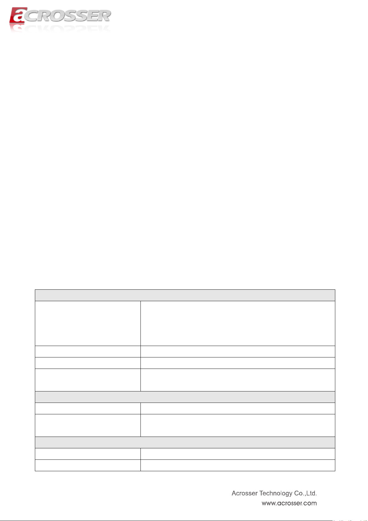
Specification
CPU
Intel Core i7 3517UE 1.7GHz
Intel Core i3 3217UE 1.6GHz
Intel Celeron Processor 1047UE 1.4GHz
Intel Celeron Processor 927UE 1.5GHz
Chipset
Intel HM76
BIOS
AMI UEFI BIOS
Memory
2 x 204-pin SO-DIMM sockets support 1333/1600MHz
DDR3 up to 16GB
Video
Graphic Controller
Integrated within HM76
Video Interface
● 2 x HDMI (HDMI Type A connector)
● 1 x VGA (Combo connector)
Storage
SATA
1 x SATA III port with SATA power connector
CF
1 x Compact Flash Type II socket
Chapter 1 System Introduction
AES-HM76Z1FL series with Intel 3rd generation Core i7/i3/Celeron processor is a
multi-function in Industrial computer, which is suitable for using in all kind of applications.
Besides basic I/O ports like RS232/422/485, GPI/GPO, Combo VGA/USB/audio, it has
complete wireless solutions for 3.5G or Wi-Fi, HDMI, USB 3.0 and swappable 2.5” HDD.
AES-HM76Z1FL is an ultra slim (20mm height only) system for easy installation. With Intel
advanced CPU, it is a powerful platform to satisfy different applications. Over 20 years
experience, Acrosser solve the system thermal issues with fanless design. With 3.5G or
Wi-Fi wireless solutions, customers can save man-power and time for network cables. It also
passes IEC, FCC and CE regulations to confirm the excellent quality.
AES-HM76Z1FL is the right choice with the best performance/price ratio for your industrial
applications.
1.1. System Specifications
Page 8
8
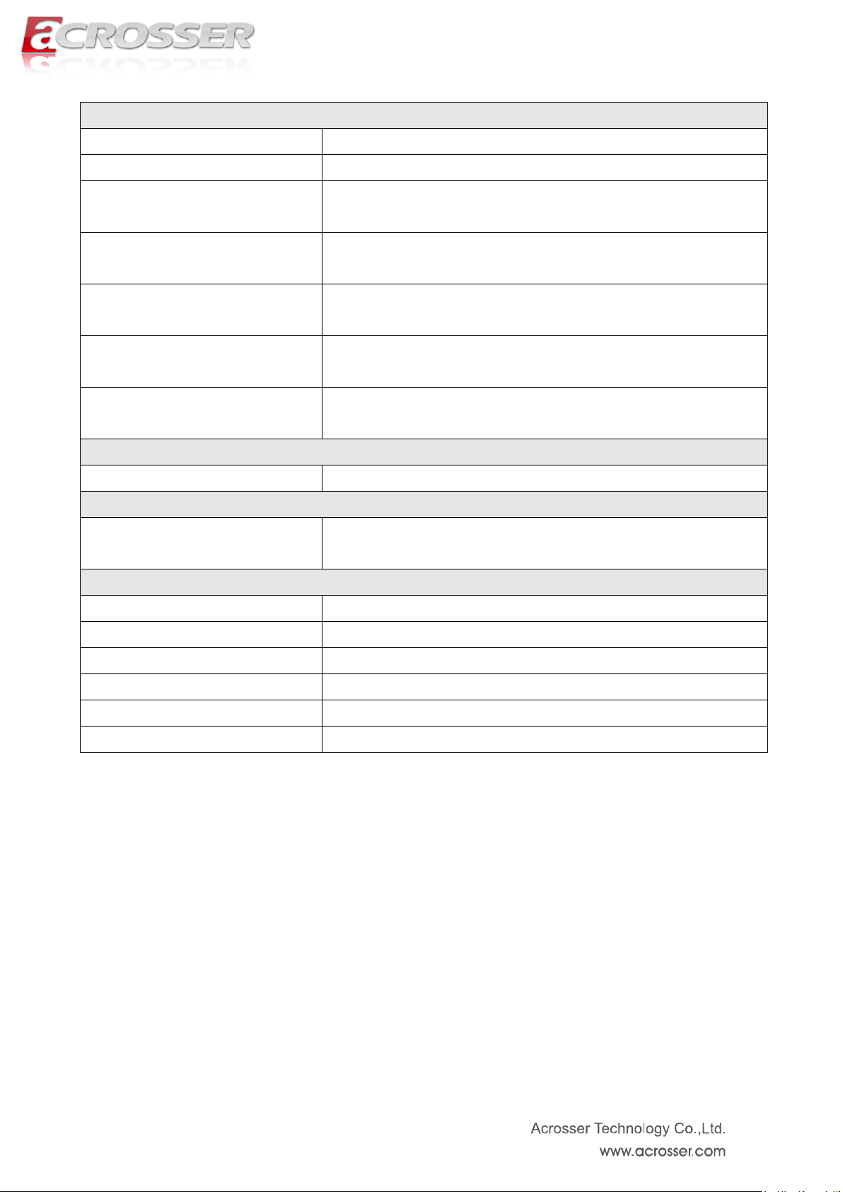
Communication
Expansion
1 x MiniPCIe socket(For 3.5G/WiFi)
SIM
1 x SIM slot (SIM card changeable without opening case)
Ethernet
● 2 x GbE (RJ45 with LED)
● Realtek RTL8111F
USB
● 3 x USB 3.0 (USB 3.0 Type A connector)
● 2 x USB 2.0 (1 for MiniPCIe / 1 for Combo connector)
Serial Ports
● 2 x RS-232 (DB9 connector)
● 2 x RS-422/485 (DB15 connector, shared with GPIO)
GPIO
● 8 x GPI (DB15 connector, shared with RS-422/485)
● 8 x GPO (DB15 connector, shared with RS-422/485)
Audio
● 1 x Line-Out (Combo connector)
● Realtek ALC662
Power Requirement
Power Supply
12V/60W Power Adaptor (DC Jack)
Software
OS Support
Windows 7(32/64bit), Windows 7 Embedded(32bit) ,
Fedora 17(32/64bit), Ubuntu 12.10(32/64bit)
Mechanical & Environment
Thermal
Fanless (Heatsink)
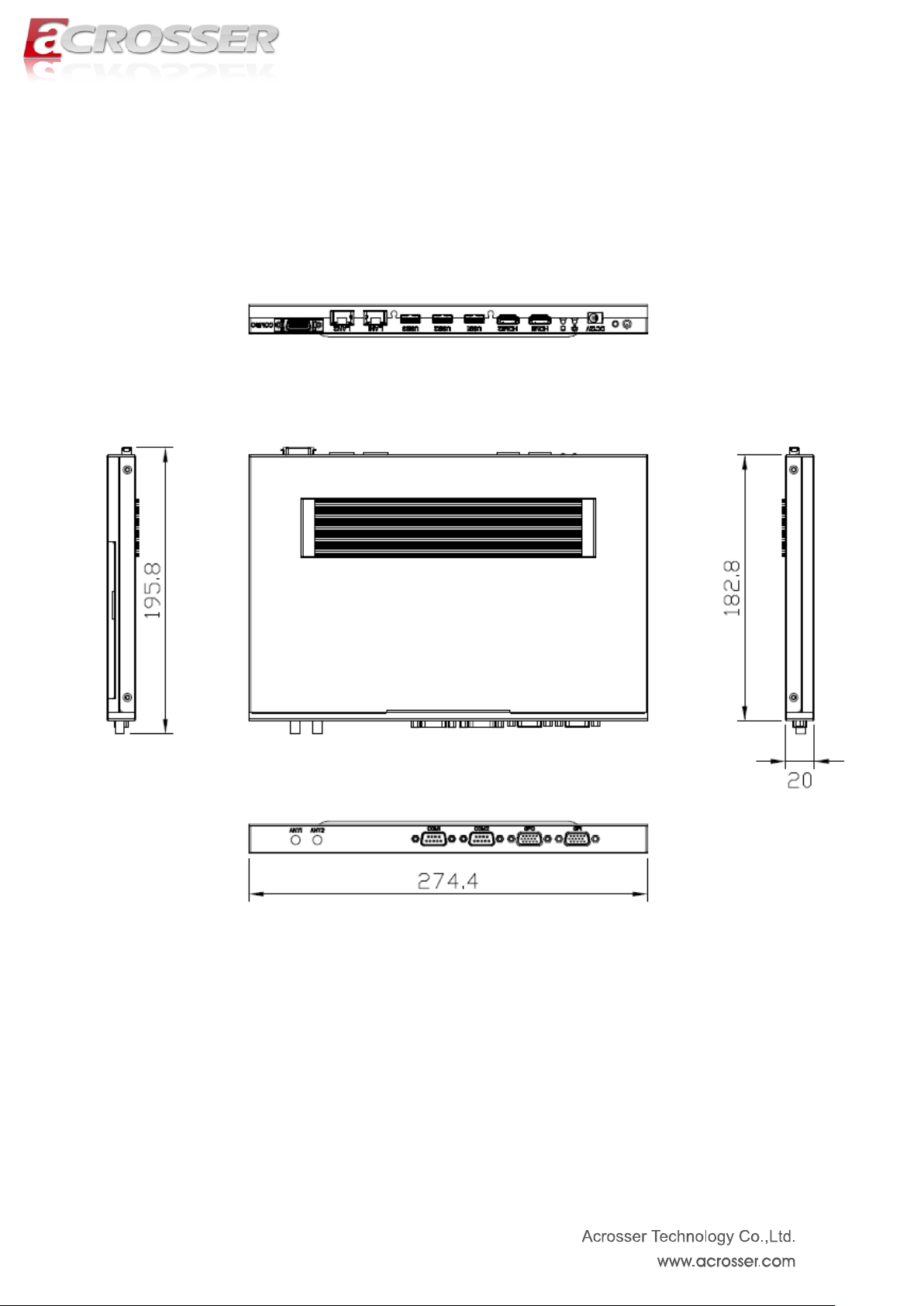
Dimension
274.4 mm x 182.8 mm x 20 mm
Operating Temp
0 ~ 45°C (32 ~ 113°F)
Storage Temp
-20 ~ 80°C (-4 ~ 176°F)
Relative Humidity
0 ~ 90%, non-condensing
Safety
CE, FCC class A
Page 9
9
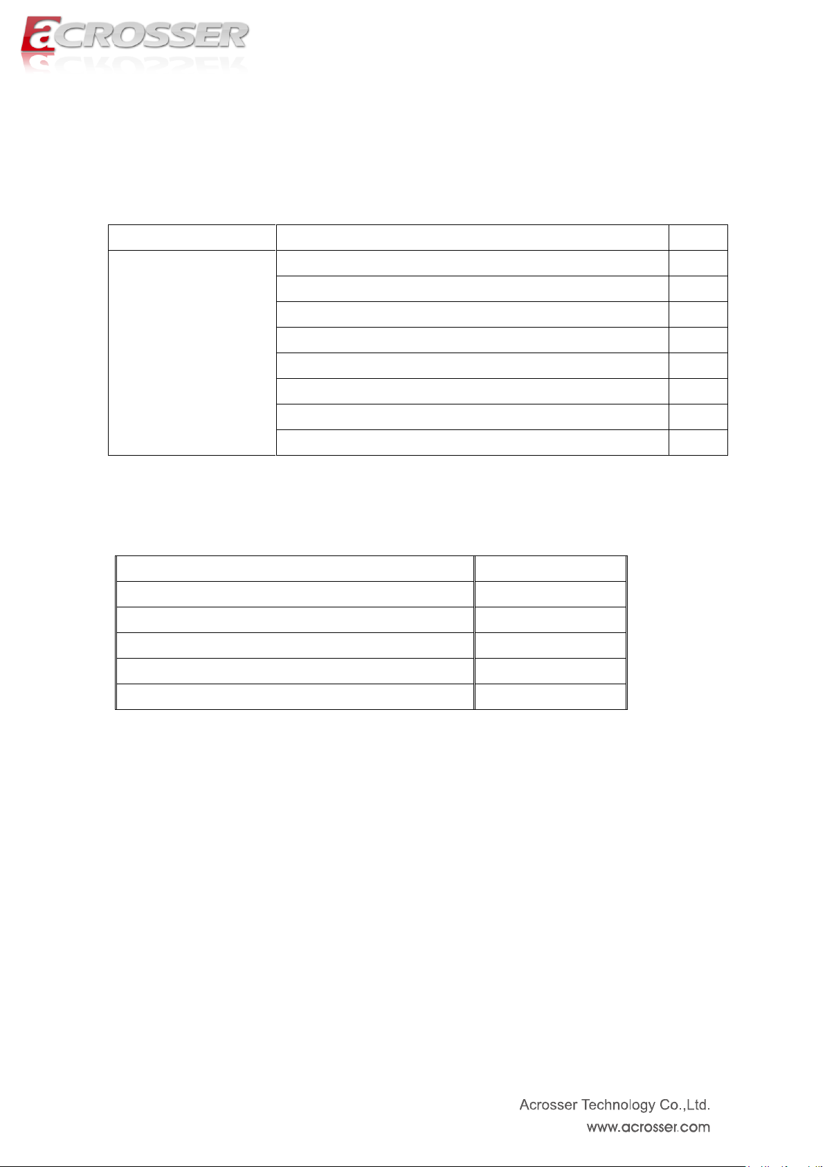
Model Name
Part Lists
QTY
AES-HM76Z1FL
AES-HM76Z1FL system
1
Quick manual
1
CD Utility
1
USA or Europe or Japan or UK power cord
1
DC12V universal adapter
1
Combo cable
1
GPIO cable
2
2.4~2.5GHz Antenna
2
Description
Connection
3.5G module
Mini-PCIe
WiFi module
Mini-PCIe
Memory DDR3 2G+2G
Memory DDR3 4G+4G
Memory DDR3 8G+8G
1.2. Packing List
Check if the following items are included in the package.
The following is optional module information. You can contact Acrosser sales rep or
local authorized channel to get more detailed info.
Note: Combo cable has 4 output connectors. Only “USB”, “VGA” and “audio” are
available features. Please connect them correctly. The remaining connector is
reserved for other products.
Page 10

10
1.3. Features
Support Intel 3rd generation Core i7 / i3 processor and Celeron Processor CPU + HM76
chipset
DDR3 non ECC SO-DIMM * 2, up to 16GB memory
HDMI x 2
Combo connector --- VGA + Audio + USB
SATA III & SATA power x 1
Swappable 2.5” HDD kit x 1
GbE chip LAN x 2
COM x 4 (2 x RS232 & 2 x RS422/485)
CF type II socket x 1 / SIM slot x 1
Mini PCIe socket x 1 (Capable for WiFi or 3.5G)
Flexible GPIO ports (8-in, 8-out)
Page 11
11
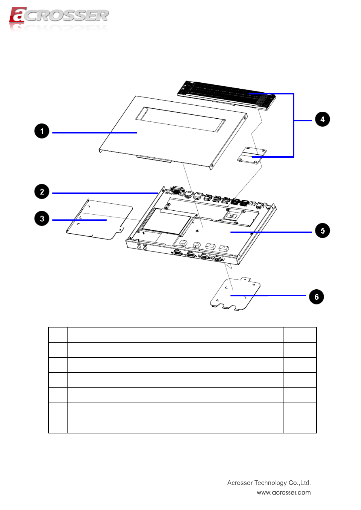
1.4. System Dissection
(1) Dimensions
Page 12
12
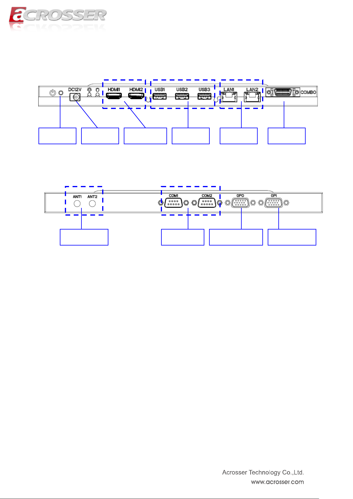
Combo
LAN * 2
HDMI * 2
Antenna * 2
USB * 3
DC Input
COM * 2
GPO (output)
GPI (input)
POWER
(2) Front Panel
(3) Back Panel
Page 13
13
Item
Description
Quantity
1
TOP COVER
1
2
BOTTOM BASE
1
3
HDD DRIVER COVER
1
4
HEATSINK MODULE SET
1
5
MAIN BOARD
1
6
DDR3 MEMORY COVER
1
(4) System Configuration
Page 14
14
Chapter 2 Procedures of Assembly/Disassembly
2.1 2.5” HDD Installation
The following instructions will guide you to install 2.5” HDD step-by-step.
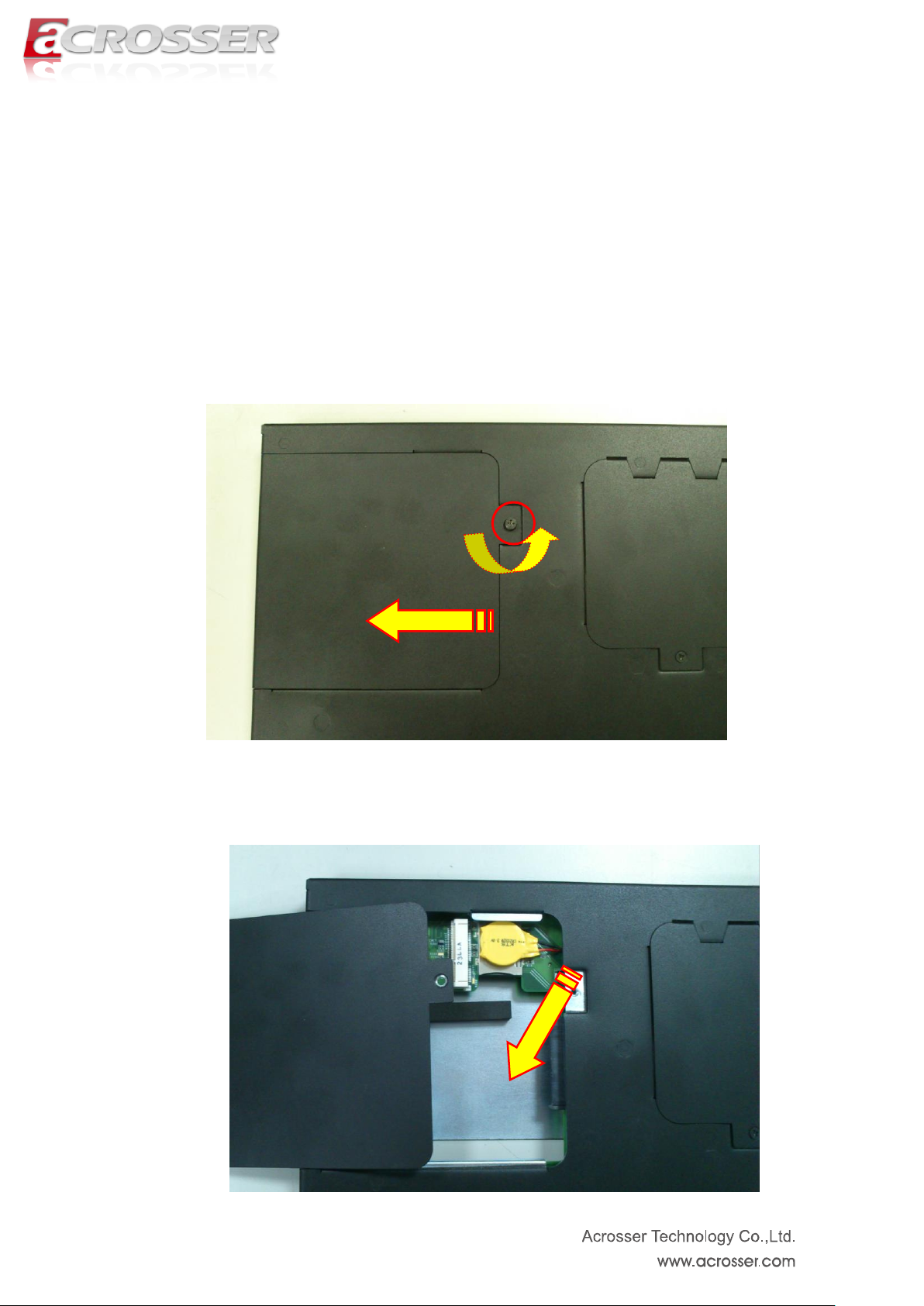
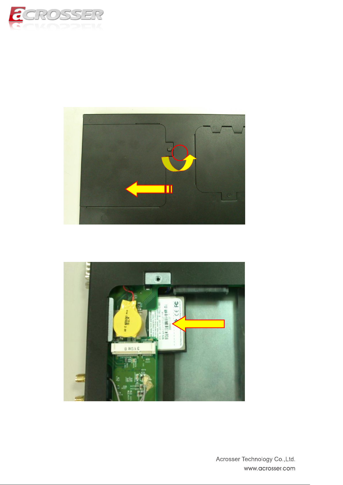
1. Unfasten screw of HDD cover and take off it.
2. There is the empty space reserved for HDD installation.
Page 15
15
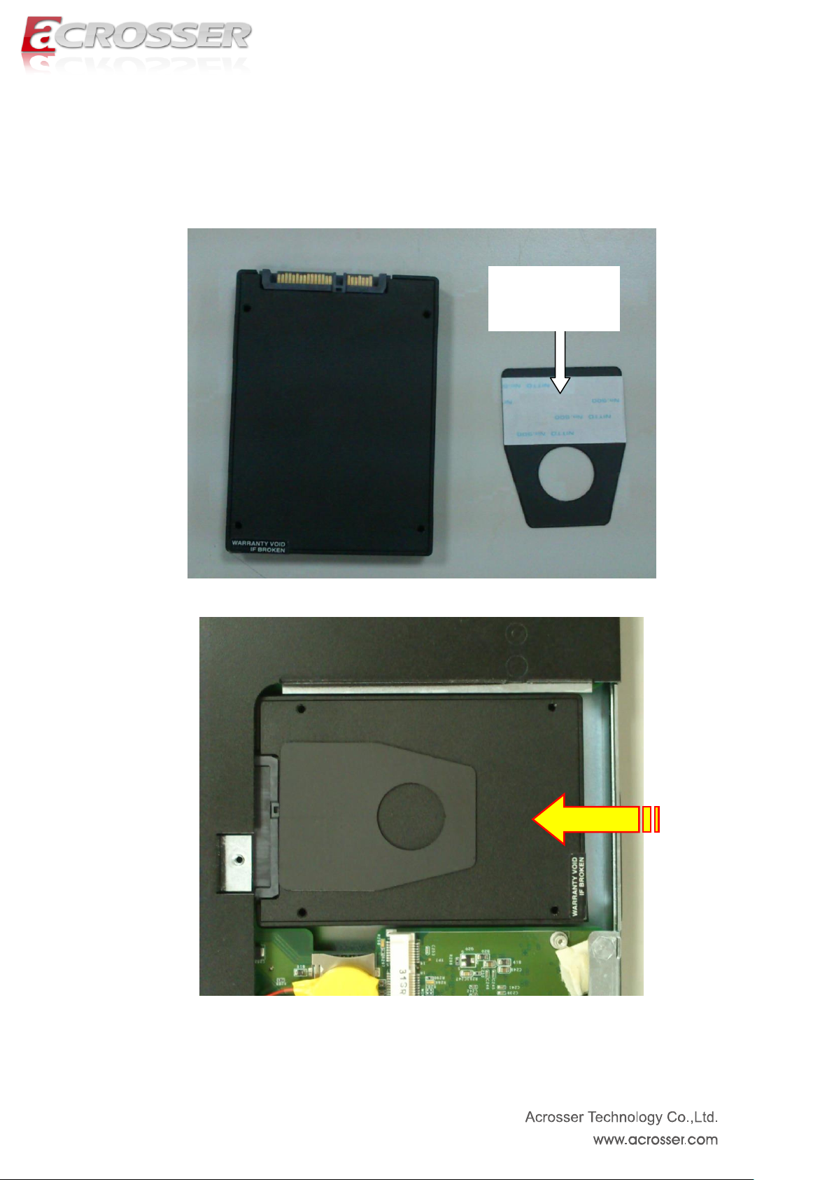
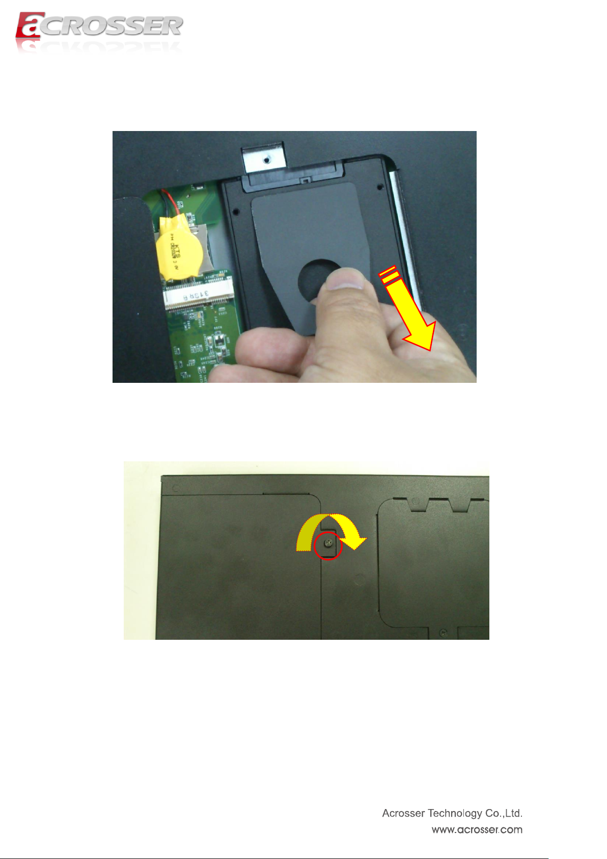
pull-tab opener
with sticker
3. We have a customized pull-tab opener which can easily un-install HDD. Please
stick HDD with this pull-tab opener before installation. Our system has equipped
with SATA connector. Please insert and push HDD into the SATA connector.
P.S. We recommend using SSD of H9.5mm.
Page 16
16
P.S. The following is reference diagram for HDD un-installation.
4. Assemble HDD cover back by fastening the screw.
Page 17
17
2.2 CF Card Installation
1. Unfasten screw of HDD cover and take off it.
2. Push CF card into CF socket.
3. Finish the CF card installation. Please assemble the HDD cover back and fasten
the screws.
Page 18
18
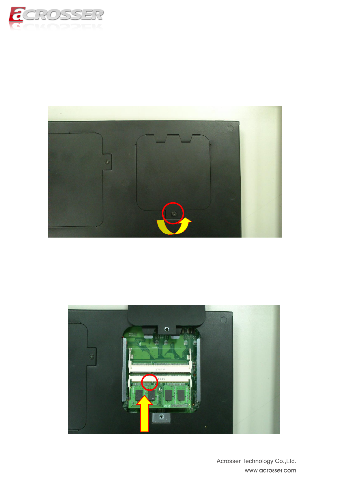
2.3 Memory Installation
1. Unfasten screw of memory cover and take off it.
2. Install the DDR3 memory into the socket.
Page 19
19
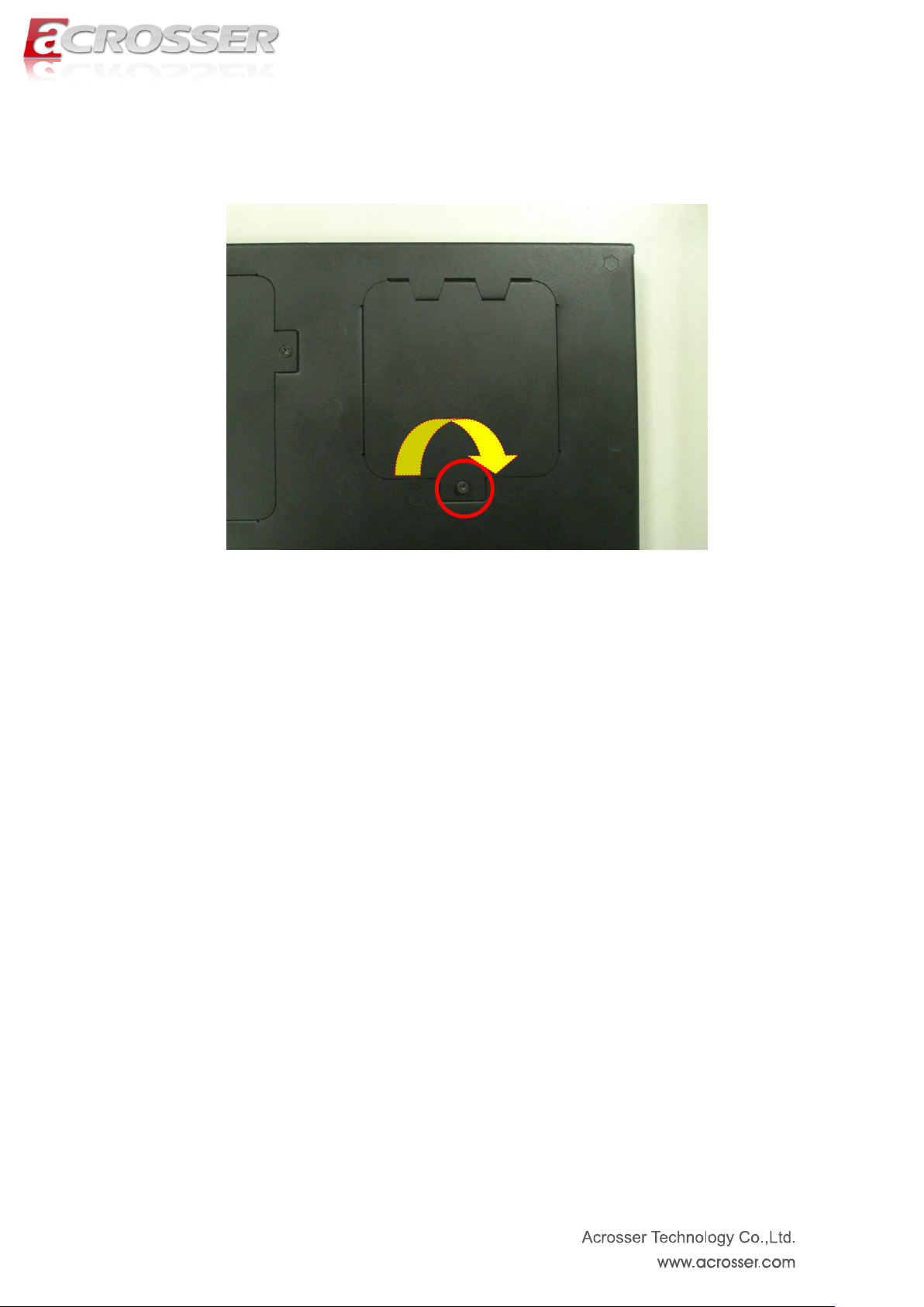
3. Assemble memory cover back by fastening the screw.
Page 20

20
Board Guide
Page 21

21
Chapter 3 Board Introduction
AMB-HM76Z1 series with Intel 3rd generation Core i7/i3/Celeron processor is a
multi-function in Industrial main board, which is suitable for using in all kind of applications.
Besides basic I/O ports like RS232/422/485, GPI/GPO, Combo VGA/USB/audio, it has
complete wireless solutions for 3.5G or Wi-Fi, HDMI, USB 3.0 and swappable 2.5” HDD.
AMB-HM76Z1 is the right choice with the best performance/price ratio for your industrial
applications.
3.1. Specifications
Support Intel 3rd generation Core i7 / i3 processor and Celeron Processor CPU + HM76
chipset
DDR3 non ECC SO-DIMM * 2, up to 16GB memory
HDMI x 2
Combo connector --- VGA + Audio + USB
SATA III & SATA power x 1
Swappable 2.5” HDD kit x 1
GbE chip LAN x 2
COM x 4 (2 x RS232 & 2 x RS422/485)
CF type II socket x 1 / SIM slot x 1
Mini PCIe socket x 1 (Capable for WiFi or 3.5G)
Flexible GPIO ports (8-in, 8-out)
Page 22

22
3.2. Package Contents (for System)
Check if the following items are included in the package.
1 x AES-HM76Z1FL System
1 x Software Utility CD
2 x GPIO cable
1 x Quick Manual
1 x Adapter
1 x Power cord
1 x Combo cable
2 x 2.4~2.5GHz Antenna
Note: Combo cable has 4 output connectors. Only “USB”, “VGA” and “audio” are available
features. Please connect them correctly. The remaining connector is reserved for other
products.
Page 23

23
3.3. Block Diagram
Page 24

24
Chapter 4 H/W Information
This chapter describes the installation of main board. At first, it shows the Function
diagram and the layout. It then describes the unpacking information which you should
read carefully, as well as the jumper/switch settings for the main board configuration.
4.1. Mainboard illustration
Top Side
Page 25

25
Bottom Side
Page 26

26
COMBO1
PIN
SIGNAL
PIN
SIGNAL
1
USB+
11
DDCCL
2
USB-
12
NC 3 GND
13
GND
4
VCC5
14
Audo_R
5
GND
15
GND 6 RED
16
NC 7 Green
17
Audo_L
8
Blue
18
NC
9
HSYNC
19
NC
10
VSYNC
20
DDCDA
LAN2 RJ45 LAN Connector
LED
ON/OFF
Status
LED1
OFF
10Mbps
Green
100Mbps
Orange
1000Mbps
LED2
Yellow
Link/Active
OFF
LAN OFF
LAN1 RJ45 LAN Connector
4.2. Locations of IO ports & Jumper settings definition
4.2.1. COMBO and LAN Connector
Page 27

27
USB3
Standard USB 3.0 Type-A connector
1
5V
5
SS_RX -
2
Data -
6
SS_RX +
3
Data +
7
GND 4 GND
8
SS_TX -
--
-----
9
SS_TX +
USB2
USB1
HDMI2, HDMI1
PIN
SIGNAL
PIN
SIGNAL
1
DATA2+
2
GND
3
DATA2-
4
DATA1+
5
GND
6
DATA1-
7
DATA0+
8
GND
9
DATA0-
10
CLK+
11
GND
12
CLK-
13
NC
14
NC
15
DDCCL
16
DDCDA
17
GND
18
+5V
19
HPD
4.2.2. USB Connector
4.2.3. HDMI Connector
Page 28

28
LED2
HDD LED
LED1
Power LED
DC1
DC Power Input
PIN
DEFINE
1
Power IN
2
GND 3 GND
PWR1
Push this button to Power On the system.
4.2.4. Power/HDD LED, DC1, PWR1
Page 29

29
GPIO2 / COM4
GPI Pin Define:
PIN
SIGNAL
PIN
SIGNAL
1
GPI0 2 GPI1
3
GPI2
4
GPI3
5
GND
6
GND
7
TX4+ 8 TX4-
9
RX4+
10
RX4-
11
GPI4
12
GPI5
13
GPI6
14
GPI7
15
Reserved
16
NC
GPIO1 / COM3
COM2, COM1
GPO Pin Define:
PIN
SIGNAL
PIN
SIGNAL
1
GPO0
2
GPO1
3
GPO2
4
GPO3
5
GND
6
GND
7
TX3+ 8 TX3-
9
RX3+
10
RX3-
11
GPO4
12
GPO5
13
GPO6
14
GPO7
15
Reserved
16
NC
Only For RS-232 Function
Pin
SIGNAL
1
DSR
2
DCD
3
RTS
4
SIN 5 CTS
6
SOUT 7 RI 8 DTR 9 NC
10
GND
4.2.5. GPIO1, GPIO2, COM1, COM2, COM3, COM4
Page 30

30
CF1
CF CARD Type II Socket
CN_SATA1(only support 5V device)
PIN
Signal
PIN
Signal
1
GND
2
TX+
3
TX-
4
GND
5
RX-
6
RX+
7
GND
8
NC
9
NC
10
NC
11
GND
12
GND
13
GND
14
VCC5
15
VCC5
16
VCC5
17
GND
18
NC
19
GND
20
NC
21
NC
22
NC
4.2.6. CF1
4.2.7. CN_SATA1, SIM1, MINIPCIE1
Page 31

31
SIM1
MINIPCIE1
SIM Card Holder
Connects to 3.5G Cell phone SIM
Card.
MINI PCI Express
Connector
CN_DIMM_1 / CN_DIMM_2
DDR3 non ECCSO-DIMM
connector
SW1 / SW3 (COM3 / COM4 RX
Terminator resistor selection )
SW2 / SW4 (COM3 / COM4 TX
Terminator resistor selection )
Default : All Off
Default : All Off
4.2.8. CN_DIMM_1, CN_DIMM_2, SW4, SW3, SW2, SW1
Page 32

32
Chapter 5 BIOS Settings
This chapter describes the BIOS menu displays and explains how to perform common
tasks needed to get the system up and running. It also gives detailed explanation of the
elements found in each of the BIOS menus. The following topics are covered:
Main Setup
Advanced Setup
Chipset Setup
Boot Setup
Security Setup
Save & Exit Setup
Page 33

33
5.1. Main Setup
Once you enter the AMI BIOS™ CMOS Setup Utility, the Main Menu will appear on the
screen. Use the arrow keys to highlight the item and then use the < + > < - > keys to select
the value you want in each item.
Note: Listed at the bottom of the menu are the control keys. If you need any help with the
item fields, you can press the <F1> key, and it will display the relevant information.
Page 34

34
Option
Choice
Description
SATA Configuration
N/A
SATA Device Options Settings
F81216 Second
Super IO
Configuration
NA
System Second Super IO Chip Parameters.
W83627DHG Super
IO Configuration
N/A
System Super IO Chip Parameters.
W83627DHG HW
Monitor
NA
Monitor hardware status
5.2. Advanced Setup
Page 35

35
Option
Choice
Description
SATA Configuration
Enable / Disable
Enable or disable SATA Device.
SATA Mode
Selection
IDE / AHCI
Determines how SATA controller(s) operate.
Port 1
Enable / Disable
Determines how SATA controller(s) operate.
CF CARD
Enable / Disable
Determines how CF CARD operate.
5.2.1 SATA Configuration
Page 36

36
Option
Choice
Description
COM 1 ~ Com 2
Configuration
NA
Set Parameters of COM1 ~ COM2
COM 3 ~ Com 4
Configuration
NA
Set Parameters of COM3 ~ COM4
COM3 422/485
function
RS-422 / RS-485
Enable COM_3 422 function or only 485 function
COM4 422/485
function
RS-422 / RS-485
Enable COM_4 422 function or only 485 function
5.2.2 F81216 Second Super IO Configuration
Page 37

37
Option
Choice
Description
Parallel Port
Configuration
NA
The Parallel Port used as the GPO
5.2.3 W83627DHG Super IO Configuration
Page 38

38
5.2.4 W83627DHG HW Monitor
Page 39

39
Option
Choice
Description
LAN 1 ~2
Enabled / Disabled
Control the LAN port Enable / Disable.
Audio
Disabled / Auto
Control Detection of the Azalia device.
Disabled = Azalia will be unconditionally disabled.
Auto = Azalia will be enabled if present, disabled otherwise.
SB USB
configuration
N/A
SB USB Configuration settings
Graphics
Configuration
N/A
Graphics Parameters
5.3. Chipset Setup
Page 40

40
Option
Choice
Description
xHCI Mode
Disabled / Auto /
Smart Auto
Mode of operation of xHCI controller.
EHCI1 ~ 2
Enable / Disable
Control the USB EHCI (USB 2.0) functions. One EHCI
controller must always be enabled.
Legacy USB Support
Enabled / Disabled
/ Auto
Enables Legacy USB support.
AUTO option disables legacy support if no USB devices are
connected.
Disable option will keep USB devices available only for EFI
applications.
5.3.1. SB USB Configuration
Page 41

41
Option
Choice
Description
DVMT Pre-Allocated
32M / 64M / 96M / 128M /
160M / 192M / 224M / 256M
/ 288M / 320M / 352M /
384M / 416M / 448M / 480M
/ 512M / 1024M
Select DVMT 5.0 Pre-Allocated (Fixed)
Graphics Memory size used by the
Internal Graphics Device.
DVMT Total Gfx Mem
128M / 256M / MAX
Select DVMT5.0 Total Graphic memory
size used by the Internal Graphics
Device.
Primary IGFX Boot
Display
VBIOS Default / D_SUB /
HDMI 1 / HDMI 2
Select the Video Device which will be
activate4d during POST. This has no
effect if external graphics present.
Secondary boot display selection will
appear based on your selection. VGA
modes will be supported only on primary
display
5.3.2. Graphics Configuration
Page 42

42
Option
Choice
Description
Setup Prompt
timeout
2
Number of seconds to wait for setup activation key. 65535
(0xFFFF) means indefinite waiting.
Boot up Num Lock
State
On / off
Select the keyboard NumLock state
Boot Logo
Enables / disables
Enables or disables Quiet Boot option
Fast Boot
Enables / disables
Enables or disables boot with initialization of a minimal set
of devices required to launch active boot option. Has no
effect for BBS boot options.
5.4. Boot Setup
Choose boot priority.
Page 43

43
Option
Choice
Description
Administrator
Password
NA
Set Administrator Password
Secure boot
Enables / disables
Secure Boot flow control. Secure Boot is possible only if
System runs in User Mode
5.5. Security setup
Page 44

44
option
Choice
Description
Save Changes and Exit
Pressing <Enter> on
this item for save
changes and exit.
Exit system setup after saving the changes.
Discard Changes and
Exit
Pressing <Enter> on
this item for discard
changes and exit.
Exit system setup without saving any changes.
Save Changes
Pressing <Enter> on
this item for
confirmation: Load
Previous Values
Save Changes done so far to any of the setup options.
Discard Changes
Pressing <Enter> on
this item for
confirmation: Save
configuration
Discard Changes done so far to any of the setup options.
5.6. Save & Exit Setup
Page 45

45
Restore Defaults
Pressing <Enter> on
this item for
confirmation: Load
Previous Values
Restore/Load Default values for all the setup options.
Save as User Defaults
Pressing <Enter> on
this item for
confirmation: Load
Optimized Defaults
Save the changes done so far as User Defaults.
Restore User Defaults
Pressing <Enter> on
this item for
confirmation: Save
configuration
Restore the User Defaults to all the setup options.
Page 46

46
Chapter 6 Function Description
6.1. Digital Inputs
There are 8 clamped diode protection digital inputs. You can read the status of any input
through the software API. These digital inputs are general purpose input. You can define
their purpose for any digital input function. The detailed information please refers to Software
Programming Guide for how to use the API.
Following diagrams state how to connect the digital inputs to devices on the system.
Page 47

47
6.2. Digital Outputs
There are 8 clamped diode protection digital outputs. You can control the output status of
these digital outputs through the software API. The eight digital outputs are capable sink
maximum 500 mA current for each channel and maximum output voltage is 12V. These
digital outputs are general purpose outputs. The detailed information please refers to
Software Programming Guide for how to use the API.
Following diagrams state how to connect the digital outputs to devices on the system.
6.3. Watchdog Timer
If you set a watchdog timer, you can use it to reset the system when system hangs up due to
hardware issue. After you set the watchdog timer, the software shall re-set the timer to
re-start a new cycle before it time-out. Please refer to Chapter 6 Software Installation and
Programming Guide for how to set the watchdog timer.
6.4. Serial ATA (SATA)
There is one SATA III port on the main board. There is also one SATA power connectors
(5V only power) for the SATA hard disk. Please be careful about it when you install SATA
hard disk driver.
Page 48

48
GPI O2 / COM4 pin definition
PCBA
PIN
SIGNAL
PIN
SIGNAL
1
GPI0 2 GPI1
3
GPI2
4
GPI3
5
GND 6 GND
7
TX4+ 8 TX4-
9
RX4+
10
RX4-
11
GPI4
12
GPI5
13
GPI6
14
GPI7
15
Reserved
16
NC
DB15
PIN
SIGNAL
PIN
SIGNAL
1
GPI0
2
GPI1
3
GPI2
4
GPI3
5
GND
6
GND
7
TX4+ 8 TX4-
9
RX4+
10
RX4-
11
GPI4
12
GPI5
13
GPI6
14
GPI7
15
Reserved
N/A
N/A
GPIO1 / COM3 pin definition
PCBA
PIN
SIGNAL
PIN
SIGNAL
1
GPO0
2
GPO1
3
GPO2
4
GPO3
5
GND 6 GND
7
TX3+ 8 TX3-
9
RX3+
10
RX3-
11
GPO4
12
GPO5
13
GPO6
14
GPO7
15
Reserved
16
NC
DB15
PIN
SIGNAL
PIN
SIGNAL
1
GPO0
2
GPO1
3
GPO2
4
GPO3
5
GND
6
GND 7 TX3+
8
TX3-
9
RX3+
10
RX3-
11
GPO4
12
GPO5
13
GPO6
14
GPO7
15
Reserved
N/A
N/A
6.5. USB
There are three USB 3.0 connectors on the main board. USB 3.0 signals are compatible with
USB 2.0 signals. You can connect USB 3.0 or 2.0 devices without any problems. There
are also two USB 2.0 signals used by mini-PCIe and combo USB interface.
6.6. GPI / GPO connector definition
Page 49

49
GPI / GPO cable color definition
GPI/GPO DB15 cable
PIN
Color
PIN
Color
1
Brown
2
Orange
3
Green
4
Blue
5
Black 6 Glay
7
Red/White
8
White
9
Red
10
Purple
11
Light Green
12
Light Blue
13
Pink
14
Brown/White
15
Yellow
N/A
N/A
Page 50

50
Chapter 7 Driver And Utility Installation
7.1. Introduction to Driver CD Interface
Acrosser provides the driver CD, which includes the drivers, utilities, applications and
documents. For Windows environment, it can be guided by the setup program; for Linux
environment, the related files can be found at folder “HM76Z1\Linux”.
Once putting the CD into the optical disk drive, it will run automatically. The driver CD
will also detect the main board information to see if they are matched. The following error
messages appear if you get an incorrect driver CD.
It indicates that the board information is not match with the driver CD. Please find the correct
CD to install the driver, thank you.
Page 51

51
AES-HM76Z1FL
7.1.1. Driver Page
Please execute “setup” program from driver CD. Then, this is the Driver Installation Page.
Page 52

52
AES-HM76Z1FL
Click the icon, all the drivers will be selected.
Page 53

53
AES-HM76Z1FL
Click the icon to install the selected drivers. It will take around 5~10
minutes to finish the installation.
Page 54

54
AES-HM76Z1FL
After complete installation, please click ‘Yes’ to restart the system.
Page 55

55
Click this icon to browse this CD content.
Page 56

56
AES-HM76Z1FL
7.1.2. Utility Page
Page 57

57
Customers can use “Test Utility” to verify system GPIO, WatchDog, H/W Monitor and COM
Mode features.
Page 58

58
AES-HM76Z1FL
7.1.3. Application Page
Page 59

59
AES-HM76Z1FL
Please install Intel MEI and Acrosser Driver into the system. Windows OS will create
“AcroDev” device.
Page 60

60
AES-HM76Z1FL
7.1.4. Documents Page
Double click on one of the items to open the manual.
Page 61

61
Chapter 8 Software Installation and
Programming Guide
8.1. Introduction
8.1.1. Overview
This model provides four type APIs which are GPI/GPO interface, Watchdog timer
interface, Hardware Monitor interface and Serial Mode interface. Users can use the
GPI/GPO API configure and access the GPI/GPO interface and the Watchdog timer. The
GPI/GPO has eight input pins and eight output pins. The Watchdog timer can be set to
1~255 seconds. Setting the timer to zero disables the timer. The remaining seconds of the
timer to reboot can be read from the timer. The Hardware Monitor API can get CPU
Temperature, System Temperature, CPU Core Voltage, 5V Voltage, 12V Voltage, and 3.3V
Voltage. Serial Mode can get and set COM3 and COM4 current status is RS422, RS485
Mode.
Page 62

62
8.2. API List and Descriptions
8.2.1. General
1. Syntax:
lib_init(void)
Description: library initialization, using this library must call this function first.
Parameters:
None.
Return Value: 0:Successful, -1:Fail.
2. Syntax:
lib_close(void)
Description: library close, when you not used this library must call this function.
Parameters:
None.
Return Value: 0:Successful, -1:Fail.
Page 63

63
8.2.2. GPIO
1 Syntax:
get_gpi_status(int pin)
Description: Get the status of GPIO input pins status.
Parameters:
This function takes an integral variable as the parameter.
The pin0 ~ 7 is pins.
Return Value: 1:HIGH, 0:LOW.
2 Syntax:
get_gpo_status(int pin)
Description: Get the status of GPIO output pins status.
Parameters:
This function takes an integral variable as the parameter.
The pin0 ~ 7 is pins.
Return Value: 1:HIGH, 0:LOW.
3 Syntax:
set_gpo(int pin, int value)
Description: Set the status of GPIO Output value.
Parameters:
Set value 0 is Low, 1 is High(Linux)
Return Value: None
Page 64

64
8.2.3. Watchdog
1. Syntax:
wdt_start(int value)
Description: This function of the watchdog time to start counter.
Parameters: The parameter ‘value’ is the value to set to watchdog timer register. The
range is 1~ 255 .
Return Value: None.
2. Syntax:
wdt_stop(Void)
Description: Any time call this function will stop Watchdog Timer.
Parameters: None.
Return Value: None.
3. Syntax:
get_wdt_count()
Description: This function read the value of the watchdog time counter.
Parameters: None.
Return Value: This function returns the value of the time counter.
Page 65

65
8.2.4. Hardware Monitor
1. Syntax:
get_cpu_temp(void)
Description: Get the CPU Temperature.
Parameters: None
Return Value: An Integral number.
2. Syntax:
get_sys_temp(void)
Description: Get the System Temperature.
Parameters: None
Return Value: An Integral number.
3. Syntax:
get_cpu_core_voltage(void)
Description: Get the CPU Core Voltage.
Parameters: None
Return Value: An float number.
4. Syntax:
get_5_voltage(void)
Description: Get the 5V Voltage.
Parameters: None
Return Value: An float number.
5. Syntax:
get_12_voltage(void)
Page 66

66
Description: Get the 12V Voltage.
Parameters: None
Return Value: An float number.
6. Syntax:
get_33_voltage(void)
Description: Get the 3.3V Voltage.
Parameters: None
Return Value: An float number.
Page 67

67
8.2.5. Serial Mode
1. Syntax:
get_comport_mode(int com)
Description: Get the Com port mode.
Parameters: 0:Com3, 1:Com4
Return Value: 0:RS485, 1:RS422
2. Syntax:
set_comport_mode(int com, int mode)
Description: Set the Com port mode.
Parameters: 0:Com3, 1:Com4.
0:RS485, 1:RS422
Return Value: None.
Page 68

68
FAQ
Why Linux operating system cannot re-install by the same storage device?
Make sure the original data had been cleaned on the storage device which will be installed for.
- It is recommendation to format the storage device before the installation.
Why the display abnormally on screen during Linux installing?
1. Change the other one monitor and try to install again.
2. OS installs in basic graphics mode.
Why the display resolution only for 800x600 and 1024x768 at X Window under Basic
Graphic Mode?
1. Make sure the Vender and Project of monitor detected correctly on the Display configuration.
2. Contact your monitor vender to get the driver for Linux.
3. To adjust setting in XORG.CONF.
- To determine the interval between the two frequencies (Max. and Min.) for both horizontal scanning and
vertical scanning which are by your monitor supporting.
For example:
HorizSync 30.0 - 80
VertRefresh 50 - 75
- Add the frequencies in XORG.CONF for that "vesa" device and monitor.
- Reboot system.
Does my system support Windows 8?
The system is designed and verified with , Windows 7, Fedora 17 and Ubuntu 12.10. But, we did not verify this
system with Windows 8. Please check with Acrosser local sales rep. or authorized channels who will help you to
confirm whether we have provided new Windows 8 driver..
Why do we get error message when we execute utility program?
1. Make sure all the drivers have been installed correctly.
2. If the problem did not solve, please contact Acrosser FAE or authorized channels.
What can I do if my system does not power on?
If your system can not power on via adapter, below are a few steps you can follow to attempt to correct the
issue.
Ensure that the power cord and AC adapter are plugged solid and not loose fitting.
Page 69

69
Ensure the adapter output is DC 12V (min. 60W)
Ensure the DC 12V output correctly connect to the system.
Attempt to use a different electrical outlet or a different adapter.
If your system can not power on via ATX PSU, below are some steps you can fellow to attempt to correct this
problem.
ATX PSU has some protections. Ensure that PSU PS_ON# signal connect to GND and the PSU
output DC 12V to the system.
Because the system only use DC 12V, it will not consume 3.3V and 5V output. Some PSUs could
mis-judge the situations and stop any voltage output.
Ensure the DC 12V output correctly connect to the system.
Attempt to use a different electrical outlet or a different PSU.
No display when power on?
1. Make sure all cables are connected well and the power is on:
2. Restore CMOS default setting via clear CMOS jumper, then reboot the system
3. If the problem did not solve, please keep the necessary components (CPU, memory, keyboard and HDD)
to test:
4.1 If the system could power on well with the above configuration, please plug the other components back
one by one to find out which one may cause this problem.
4.2 If the system still could not power on, please listen if there is any warning beeps.
4.2.1 Memory issue:
A. Clean the Golden Finger of memory
B. Clean the memory slots
C. Leave only one memory stick to test
D. If convenient, please change different memory modules to test again
4.2.2 Graphics card issue:
A. Clean the Golden Finger of graphics card
B. Clean the graphics card slots
C. Try to test the onboard graphics card if there is onboard VGA integrated
D. If convenient, please change different graphic cards to test again
4.2.3 CPU issue:
A. Check whether the CPU is in our supported CPU
B. Check whether there are any damagers of your CPU or CPU socket.
C. Check whether the CPU fan is correctly connected
Page 70

70
Model: AES-HM76Z1FL
P/N:010040xxx
S/N:xxxxxxx I
CPU: i7 3517UE
Memory: DDR3 non ECC 4GB
Where is the serial number located on my system?
The serial number (S/N) is an alpha-numeric character located on the bottom or side chassis.
(reference only)
How do I connect the second monitors to my system?
1. Basically, there are “duplicate” and “extend” mode for the second monitor.
A. duplicate mode –- you will see the same contents on both monitors.
B. extend mode – your monitors display different contents, and you can drag your contents between
the first and second monitor.
2. Ensure the display device setting is correct and monitor cables are connected well.
A. For device setting, it could be different because of different operating systems and S/W version
B. You can search from “Google” as reference setting.
3. If the problem did not solve, please contact Acrosser FAE or authorized channel.
My system has audio problem?
If your system has audio problem, below are a few steps you can follow to attempt to correct the issue.
Ensure that the BIOS enable on-board audio function (reference diagram)
.
Ensure the audio driver and device has been installed successfully.
Page 71

71
Ensure speaker connect to the right connector.
Sometimes, audio has been set “MUTE”. Please adjust the audio volume louder.
If the problem persists, please contact Acrosser FAE or local authorized channel.
My system can not connect to internet?
If your system can not connect to internet, below are a few steps you can follow to attempt to correct the issue.
Ensure that network adapter can be recognized in Device Manager
If there is question mark or exclamation mark in the network adapter, please re-install your OS and
network driver. If the problem did not solve, please contact your local FAE or sales rep for tests.
Page 72

72
Ensure the Network Connections/Local Area Connection is enabled (right click and choose “Enable”).
If the problem persists, please turn off firewall and anti-virus S/W. If the problem still exists, please
contact local FAE or service center for tests.
Page 73

73
If the Network Connections/Local Area Connection is showed “limited connection” (yellow
exclamation mark), please disable and enable your connection to fix this problem. Or, you can
unplug and plug the LAN cable to fix the problem. If the problem still persists, please contact your
MIS whether there are any DHCP or IP configuration or ISP/WAN setting limitation.
 Loading...