

Page 1
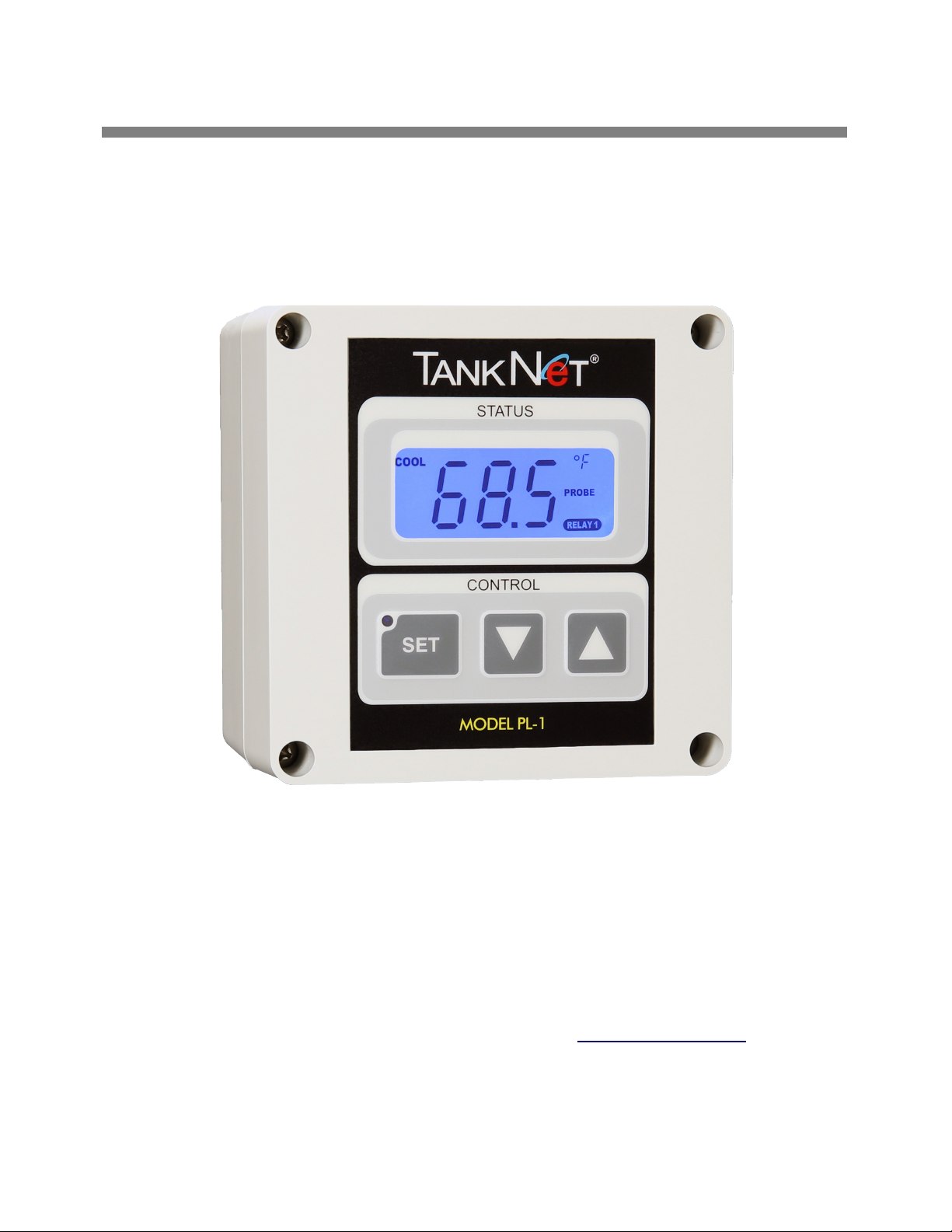
PL-1 SERIES II Thermostat
Installation Guide
Version 2.1
Acrolon Technologies, Inc.
19201 SONOMA HIGHWAY, SONOMA, CALIFORNIA 95476
Phone +1 (707) 938-1300, Fax: +1 (707) 938-1342 http://www.acrolon.com
Page 2

Page 3

TC
Chapter 1: Overview................................................................................ 1
Chapter 2: Installation..............................................................................2
Mounting.........................................................................2
Internal Wiring................................................................4
Installing the LID............................................................7
Applying Power..............................................................8
Chapter 3: Specifications.........................................................................
Table of Contents
.
Page 4

1
Overview
This manual covers installation of Acrolon's PL-1 thermostat., an industrial-grade temperature controller
designed specifically for use wine tanks.
The PL-1 should be mounted onto a protective ice shield on the tank and wired to the cooling and/or heating
valves via 16-18AWG 300V wire run inside flex conduit
Key Features:
• Calibration-Free Temperature Sensing
• Two Internal Relays (5A @ 120VAC)
• Easy-to-Use Front Panel Controls and Display
• Industrial-Grade Power Line Communications
• NEMA-4X Rated for Indoor and Outdoor Use
NO USER SERVICEABLE PARTS INSIDE
ONLY AUTHORIZED, LICENSED PERSONNEL MAY INSTALL OR
SERVICE THIS PRODUCT
TO PRESERVE THE PROTECTION AFFORDED BY THIS EQUIPMENT,
CLOSE ADHERENCE TO THE PROCEDURES AND INSTRUCTIONS
CONTAINED IN THIS DOCUMENT IS REQUIRED. FAILURE TO
FOLLOW THE INSTRUCTIONS GIVEN HERE MAY CAUSE FIRE,
PERSONAL INJURY OR VOID OR VOID PRODUCT WARRANTY.
1
Page 5

2
Installation
HAZARDOUS VOLTAGE. Contact may cause electric shock, burn or result
in death. Turn off and lock out system power before servicing or installing.
Mounting:
1. Install the four mounting brackets supplied with the thermostat per Figure 2.
2. Fasten the PL-1 thermostat to the ice shield per Figure 3 using four #10 x 3/8” long stainless steel selftapping screws. Note that pilot holes might be required depending upon the material used for the ice
shield. Hand tighten each screw to between 8 and 12 inch pounds. DO NOT OVER TORQUE
3. With the thermostat securely fastened to the the ice shield, install 1/2” flexible conduit between the
thermostat's leftmost bottom inlet and the power source. Secure conduit with liquid-tight fittings. See
Figure 1.
4. Fully install temperature probe into thermowell of tank and run the probe cable through the liquid-tight
strain-relief inlet at bottom right of the thermostat. Tighten to 8 and 12 inch pounds or until cable is
secure.
Ice Shield
PL-1 Therostat
Liquid -tight ½
Contuit Fitting
Flexible Conduit
(Power/Solenoid Wiring)
Temperature
Probe Installed
in probe-well
w/ water-tight
cable grip
Figure 1
2
Page 6

Figure 2 (above) Figure 3 (below)
3
Page 7

Internal Wiring
ELECTRICAL SHOCK HAZARD: DISCONNECT BREAKERS BEFORE
SERVICING OR INSTALLING THIS PRODUCT!
This product is intended for use single phase power distribution systems and
relies on the building's installation for short-circuit (over current) protection
and line voltage disconnect. Protective device (circuit-breaker) rating must
not exceed 20 Amps. The installer of this equipment is responsible for
provisioning this circuit-breaker, which must be located in the electrical
distribution panel (breaker-panel) of the building, in close proximity to the
PL-1 thermostat(s) and clearly labeled as being the disconnect for the product.
Compliance is checked by inspection.
CAUTION: For continued protection against risk of fire, replace only with
same type and rating of fuse.
F3: Little fuse, 218P Series, 6.3A/250V time delay, 5 x 20 mm
F1, F2: Wickmann, TE5 Series, 5.0A Time Delay, short pin
Notes:
1. This product must be connected to mains supply only by permanent field
wiring using the following wire type: THWN, 18 AWG - 250 KCMIL 300 V,
Nylon jacketed w/ high dielectric PVC insulation (UL-83, UL-1063 and UL-
758).
2. All electrical connection and conduits are to be made per National Electric Code
ANSI/NFPA70, or per the applicable code in the country of installation. Use only
conduit and conduit fittings that meet UL 797 safety standard.
3. All wire terminal splice connectors must be UL and CSA rated up to 300 V per UL
486 and temperature rated per UL Flammability UL 94V-2/HB.
4
Page 8
Internal Wiring (continued)
R2
R2
R2
Mains Wiring:
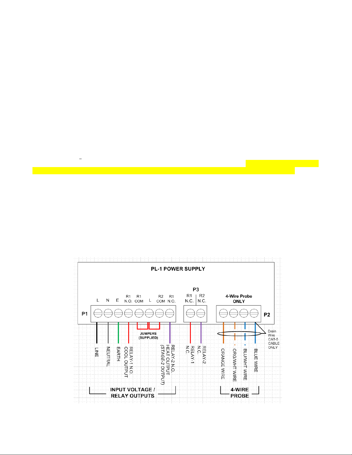
1. Pull one each of the following wires colors from the source power through the conduit to the inside of the
PL-1 power supply: GREEN (Earth), WHITE (NEUTRAL), BLACK (LINE), RED (cool output), PURPLE
or BLUE (heat output). Leave only enough extra length of wire inside the thermostat to allow for easy wire
preparation and termination. USE ONLY THWN, 18 AWG 300V WIRE.
2. Strip back insulation of each wire 1/8”.
3. Remove the power plug from P1 of the power supply and loosen the all screws terminals.
4. Cleanly install the conductor of each wire into Pl plug (with no stray strands) per wiring diagram shown in
Figure 4. Tighten the screw terminal as each wire is installed. Torque all screw terminals of P1 to 6 inch
pounds.
5. Install the power plug into the Pl receptacle on the power supply.
Probes Wiring: PL-1 Series II Controllers accept both TankNET 4-Wire and 2-Wire temperature
probes. Series II PL-1s ship with 2-wire probes unless otherwise requested. Please identify your probe
type as either 2-Wire or 4-Wire prior to reading and executing these probe wiring instructions.
4-WIRE PROBE WIRING:
1. Strip back insulation of each probe wire 1/8”.
2. Remove the probe plug from P2 of the power supply and loosen the all screws terminals.
3. Install the conductor of each probe wire into the P2 plug per wiring diagram shown in Figure 4, tightening
each screw after installing each conductor. Torque all screw terminals of P2 to 6 inch pounds.
4. Install the probe plug into the P2 receptacle on the power supply.
WARNING: FAILURE TO CONNECT PROPER INPUT VOLTAGE MAY CAUSE FIRE OR DESTROY
PRODUCT AND SHALL VOID PRODUCT WARRANTY!
6000-024-S2 = 24VAC INPUT VOLTAGE
6000-120-S2 = 120VAC INPUT VOLTAGE
Figure 4
5
Page 9

2-WIRE PROBE WIRING:
1. Install the PL-1 thermostat per Acrolon’s PL-1 Installation Guide while disregarding the 4-wire probe wiring
information provided with in it.
2. Pull approximately 6” of probe cable through the liquid-tight cable gland located at bottom right of PL-1
power supply.
3. Strip back the outer jacket of the probe cable about 1” from the cut end of the cable. Take care not to breach
the insulation of either of the two internal wires contained within the cable jacket.
4. Strip back approximately 1/8” of insulation from both the red and black wires of the probe cable.
5. Remove the 4-terminal “PROBE” plug from the PL-1 power supply.
6. Insert the RED wire into the leftmost terminal of the PROBE plug as shown in Figure 1, and secure by hand
tightening the terminal screw using a 4mm x 2.5mm standard screw driver. Insert the BLACK wire into
terminal immediately adjacent to the right of the RED wire per figure below, and secure as previously
described above.
7. If the probe cable has been extended, be sure to use shielded cable and terminate the shield or drain-wire at
JP8 per illustration below.
8. Install the PROBE plug into PL-1 display at “JP8” location.
9. Reduce excess probe cable from within the PL-1 by pulling the cable back through the cable gland of the
power supply and then tighten the gland to ensure a water-proof seal around the probe cable.
6
Page 10
PL-1 Display Installation
1. Verify internal power and probe wiring
2. Hold the PL-1 display assembly with your right hand with front panel against your palm.
3. Align inside right edge of display assembly with the right edge of the power supply assembly.
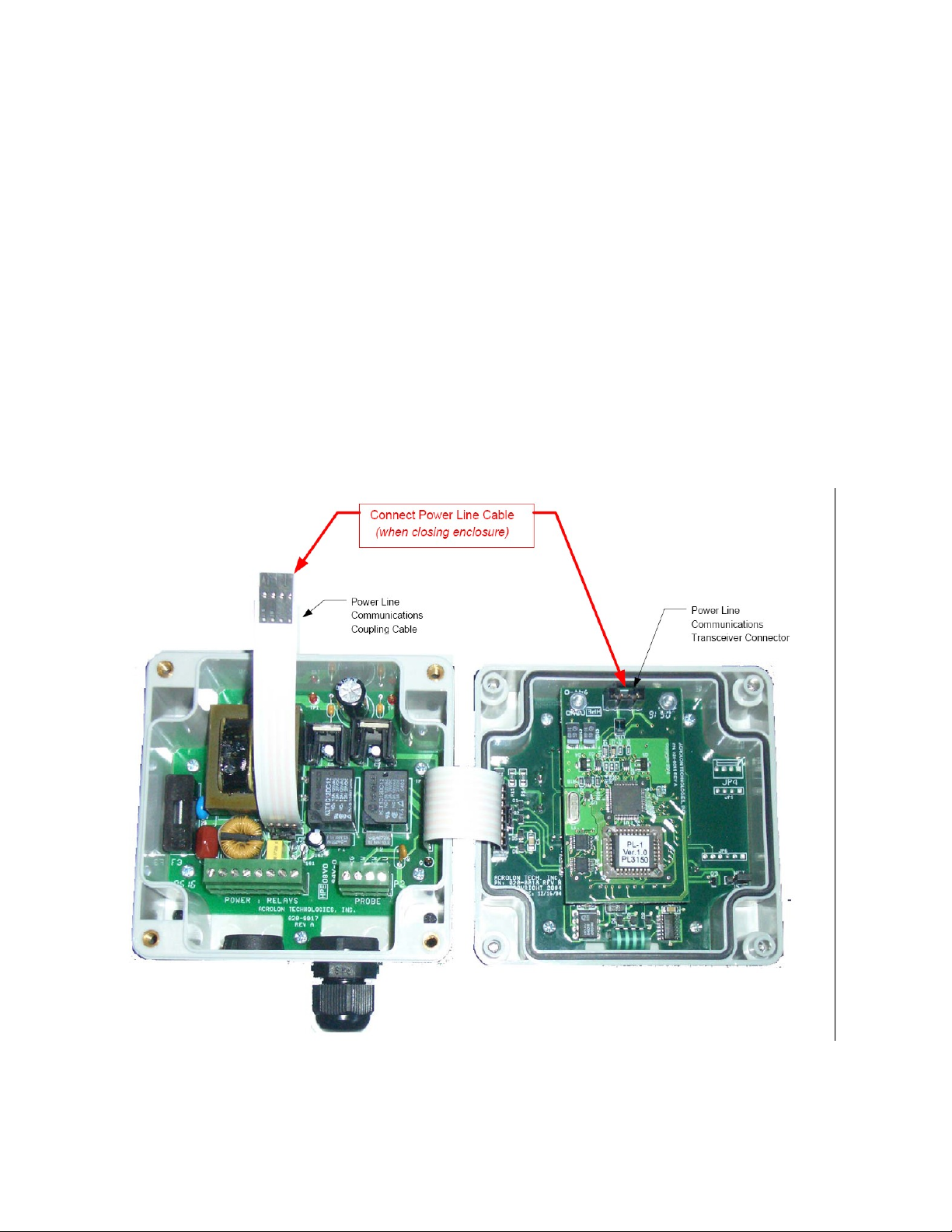
4. With your left hand connect the 8-conductor ribbon cable from the power supply to the mating
receptacle on the display assembly (see figure 5).
5. With your left hand connect the 4-conductor ribbon cable from the power supply to the mating connector
on the display assembly (see figure 5).
6. Align the mounting screws of the display assembly with the threaded holes on the power supply
assembly.
7. Using a Phillips screw driver tighten each mounting screw starting at upper left, then lower right, the
upper right, and finally lower right. Tightening the LID screws in this fashion prevents binding between
the PL-1 display and the power supply. Hand tighten ONLY to 10 to 12 inch pounds.
DO NOT OVER TORQUE.
Figure 5
7
Page 11

Applying Power
ELECTRICAL SHOCK HAZARD: BEFORE APPLYING POWER
ENSURE THAT ALL WIRING IS CORRECT AND THAT THE PL-1 LID IS
SECURELY FASTENED TO THE PL-1 POWER SUPPLY BASE.
The PL-1 thermostat connects to the mains supply through permanent field wiring via circuit-breaker located in
the electrical distribution panel of the building. This circuit-breaker serves as the disconnect for the thermostat
and should be clearly marked as such in the panel.
Apply power to the PL-1 thermostat(s) by switching ON (closing) the corresponding circuit-breaker inside the
distribution panel to which the thermostat is connected. .
8
Page 12

3
Specifications
Part Number:
The part number scheme for the PL-1 thermostat is as follows:
6000-XXX
Where: XXX: 120 or 024, indicates the power supply input voltage (120VAC or 24VAC) as measured
between line and neutral
Specifications:
Input Voltage 6000-120: 120 Vac, 50/60 Hz, 0.05A
6000-024: 24 Vac, 50/60 Hz, 0.20A
Relay Contacts COOL RELAY (N.O / COM / N.C): 5A @ 120VAC
HEAT RELAY (N.O / COM / N.C): 5A @ 120VAC
Operating Temperature 0 to +50ºC
Storage Temperature -10 to +60ºC
Network Transceiver Power Line PL-20N (1A p-p)
Enclosure Polycarbonate, UL50, NEMA-4X Rated
Safety Agency Listing ETL
9
 Loading...