

Page 1

®
OMNISTIM
Electrotherapy System
User Manual
This Manual contains confidential and proprietary information owned by Accelerated Care Plus ("ACP") which is protected by copyright. This
Manual or any portion thereof may not be photocopied, reproduced or translated to another language without the express prior written consent of
ACP. This Manual may only be used by entities who have purchased the equipment or have implemented the ACP program and are covered by
an executed Lease Agreement with ACP containing a Confidentiality Agreement, which is incorporated by reference in its entirety. This Manual
may not be used for any other purpose.
Any additional copies of the Manual shall be ordered from ACP. No changes or modifications shall be made to the Manual without prior review
and written authorization from ACP. No authorization is given to market, sell, disclose, or exploit this Manual except as for purposes of using the
Equipment as contemplated by the Lease Agreement.
ACCELERATED CARE PLUS MAKES NO WARRANTY OF ANY KIND WITH REGARD TO THIS MANUAL, INCLUDING, BUT NOT
LIMITED TO, THE IMPLIED WARRANTIES OF MERCHANTABILITY AND FITNESS FOR A PARTICULAR PURPOSE. Accelerated
Care Plus shall not be liable for errors contained herein or for incidental or consequential damages in connection with the furnishing, performance
or use of this Manual.
The information contained in this document is subject to change without notice.
500A
Revised 070101
Part No. 290500A
COPYRIGHT 2001 - 2007, ACCELERATED CARE PLUS CORP., ALL RIGHTS RESERVED
CONFIDENTIAL AND PROPRIETARY
Page 2
2 OMNISTIM
®
500A USER MANUAL
OMNISTIM® 500A
ACP manufactures a premier line of electromedical devices to assist health care professionals in the rehabilitation of
their patients. The ACP product line includes Pain Control Systems, Muscle Stimulators, Interferential Therapy, and
Ultrasound devices. Our MEGAPULSE
most recent world wide technological advances available for therapeutic application of electromedical devices.
ACP is internationally recognized for its contribution to research in the development of medical applications for
therapeutic rehabilitation. The Company sponsors and conducts research at leading health care institutions and major
universities throughout the world. This new medical frontier holds great promise and opportunity, which will result
in substantial advancements in the health care industry and for ACP.
®
, NEUROPROBE®, OMNISTIM®, and OMNISOUND
®
represent the
COPYRIGHT 2001 - 2007, ACCELERATED CARE PLUS CORP., ALL RIGHTS RESERVED
CONFIDENTIAL AND PROPRIETARY
Page 3

OMNISTIM® 500A USER MANUAL 3
TABLE OF CONTENTS
INDICATIONS & CONTRAINDICATIONS ..............................................................................................................4
Indications...........................................................................................................................................................4
Contraindications................................................................................................................................................4
Adverse Reactions ..............................................................................................................................................4
WARNINGS & PRECAUTIONS .................................................................................................................................5
Warnings.............................................................................................................................................................5
Precautions..........................................................................................................................................................6
THE OMNISTIM® 500 .................................................................................................................................................8
Delivery of the OMNISTIM® 500 ......................................................................................................................8
Introduction.........................................................................................................................................................8
Controls and Functions .......................................................................................................................................9
Factory Settings ................................................................................................................................................10
Battery Charger / Power Supply Operation ......................................................................................................11
Operational Sequence .......................................................................................................................................12
TREATMENT GUIDELINES ....................................................................................................................................13
Introduction to Medium Frequency Currents....................................................................................................13
Electrode Application Techniques....................................................................................................................14
Treatment Preparation.......................................................................................................................................16
INFECTION CONTROL EQUIPMENT AND PRINCIPLES OF USE.....................................................................17
Definitions ........................................................................................................................................................17
Universal Precautions – Body Substance Isolation...........................................................................................17
Cleaning/Disinfecting of the OMNISTIM® 500 ...............................................................................................17
Cleaning, Low Level Disinfection and Barriers................................................................................................17
Intermediate Level Disinfection........................................................................................................................17
Use of Barriers – Intermediate Level Disinfection ...........................................................................................18
MODES OF OPERATON: Protocol Reference Sheets...............................................................................................19
Interferential Current (IFC)...............................................................................................................................19
Medium Frequency Alternating Current (MFAC)............................................................................................20
Low Volt Pulsed Current (LVPC) ....................................................................................................................21
High Volt Pulsed Current (HVPC) ...................................................................................................................22
STIMULATION THERAPY MODES........................................................................................................................23
Interferential Current Therapy (IFC) ................................................................................................................23
Medium Frequency Alternating Current (MFAC)............................................................................................30
Low Volt Pulsed Current (LVPC) ....................................................................................................................35
High Volt Pulsed Current HVPC......................................................................................................................39
TROUBLESHOOTING ..............................................................................................................................................41
Service Center...................................................................................................................................................43
TECHNICAL SPECIFICATIONS..............................................................................................................................44
OMNISTIM® 500 STANDARD AND OPTIONAL ACCESSORIES .......................................................................46
Electrodes .........................................................................................................................................................47
Infection Control Supplies ................................................................................................................................47
LIMITED PRODUCT WARRANTY .........................................................................................................................48
Warranty Coverage...........................................................................................................................................48
Warranty Exclusion ..........................................................................................................................................48
Warranty Period................................................................................................................................................48
Warranty Validation .........................................................................................................................................48
Return of Defective Products............................................................................................................................49
APPENDIX - ILLUSTRATED OPERATIONAL SEQUENCE.................................................................................51
Procedure for Quick Start-Up ...........................................................................................................................51
Detailed Operational Sequence.........................................................................................................................53
Adjusting Global Factory Settings....................................................................................................................59
COPYRIGHT 2001 - 2007, ACCELERATED CARE PLUS CORP., ALL RIGHTS RESERVED
CONFIDENTIAL AND PROPRIETARY
Page 4

4 OMNISTIM
®
500A USER MANUAL
INDICATIONS & CONTRAINDICATIONS
CAUTION: Federal law restricts this device for sale or use by, or on the order of, a Practitioner
licensed by the laws of the state in which he/she practices to use or order the use of the device.
Please note that Accelerated Care Plus cannot provide medical advice. If you have specific
medical questions, please contact your healthcare professional.
Indications
The OMNISTIM
1. Symptomatic relief and management of chronic intractable pain and as an adjunctive treatment in the
management of acute pain, post surgical pain and pain associated with post-traumatic injury.
2. Relaxation of muscle spasms.
3. Re-education of muscle action.
4. Prevention or retardation of disuse atrophy.
5. Immediate post surgical stimulation of calf muscles to prevent venous thrombosis.
6. Increased local blood circulation.
®
500 is indicated for:
7. Maintaining or increasing range of motion.
Electrical muscle stimulator devices should be used under medical supervision for adjunctive therapy for the
treatment of medical diseases and conditions.
Contraindications
1. Transcutaneous electrical stimulation, or powered muscle stimulators should not be used on patients with
cardiac demand pacemakers and/or implanted defibrillators.
2. Never connect lead wires to the power line or electro-surgery equipment. Use only the lead wires
recommended or approved by the manufacturer.
NOTE: There is no contraindication to the application of Transcutaneous Electrical Stimulation or
Powered Muscle Stimulation over metal implants.
Adverse Reactions
Skin irritation and burns beneath the electrodes have been reported with the use of powered muscle stimulators.
COPYRIGHT 2001 - 2007, ACCELERATED CARE PLUS CORP., ALL RIGHTS RESERVED
CONFIDENTIAL AND PROPRIETARY
Page 5

OMNISTIM® 500A USER MANUAL 5
WARNINGS & PRECAUTIONS
CAUTION: Federal law restricts this device for sale or use by, or on the order of, a Practitioner
licensed by the laws of the state in which he/she practices to use or order the use of the device.
Please note that Accelerated Care Plus cannot provide medical advice. If you have specific
medical questions, please contact your healthcare professional.
Warnings
• Do not operate this device until the User Manual, including all Indications for Use, Contraindications, Warnings
and Precautions, have been carefully read and understood.
• Operation of this device or placement of lead wires, probes, pads and electrodes in close proximity (less than 5
feet) to an operating shortwave or microwave diathermy unit may produce instability in the device output or
burns at the treatment site. Lead wires and device can pick up the magnetic field output of the diathermy and
through induction convert it into an electrical field, transmit the energy into the patient increasing the current
density at the electrodes of applicators. Since the patient may not feel the 27 MHz frequency, they lack the
protective sensation and tissue burns could result. Short-wave field could potentially damage or reset medical
devices in close proximity to the drum applicator.
• Treatment should not be applied over the carotid sinus nerves, (located in the anterior neck triangle), including,
stellete ganglion, vagus nerve, or laryngeal or pharyngeal muscle. Particular care should be taken for patients
with a known sensitivity to the carotid sinus reflex, as carotid sinus stimulation may alter blood pressure and
cardiac contractility.
• Do not apply treatment over testes, heart or eyes. Thermal effects or electrical stimulation may affect organ
function.
• Do not apply over or in close proximity to active cancer (except in terminal / palliative / hospice care), as
therapy may increase blood flow to the tumor.
• Treatment should not be applied when high fever is present, over swollen, severe infection, (osteomyelitis,
sepsis, tuberculosis, etc.), or inflamed areas or skin eruptions, (e.g., phlebitis, thrombophlebitis, varicose veins,
etc.).
• Do not apply over the lumbar or abdominal region, or over the uterus during pregnancy (to prevent uterine
contraction), or during menstruation as therapy may temporarily increase menstrual flow.
• The long-term effects of chronic electrical stimulation are unknown. To date, the only negative effects reported
are based on skin and tissue irritation under the electrode sites associated with chronic estim use.
• Stimulation should not be applied transthoracically in the vicinity of the heart, as introduction of electrical
current into the heart may cause cardiac arrhythmias.
• Treatment should not be applied transcranially.
• Stimulation should not be applied to patients connected to patient monitoring equipment, as the stimulation may
have an affect on the proper operation of the monitoring equipment.
• Stimulation should not be applied directly over external or implanted stimulator systems, such as shunts,
infusion pumps, stomach, bladder, brain, spinal cord, bone growth, or other implanted stimulators.
• Neuromuscular electrical stimulation (NMES) should not be applied directly over or in close proximity to Deep
Vein Thrombosis (DVT), as it activates the muscle and causes muscle contractions. This should be avoided in
tissue following an acute DVT when the thrombosis is not completely resolved. Therapists should follow the
guidelines provided by the referring physician on recommended activity level and modality use. If the patient is
not permitted exercise, NMES therapy should be avoided. Generally, NMES over a DVT of six weeks or less
should be avoided altogether.
COPYRIGHT 2001 - 2007, ACCELERATED CARE PLUS CORP., ALL RIGHTS RESERVED
CONFIDENTIAL AND PROPRIETARY
Page 6

6 OMNISTIM
®
500A USER MANUAL
Precautions
• Application site and settings should be based on the guidance of the prescribing practitioner.
• All equipment and accessories should be kept out of the reach of children or unqualified persons.
• Do not connect this device to any wall outlet that has not been properly grounded, or to any electrically non-
isolated medical device.
• Use only ACP specified accessories and/or supplies with ACP devices. Do not use any power cords, or power
supplies, other than the ones provided or specified for this device. Use of any other power supply could
seriously damage the device and will void the warranty.
• When cleaning the device, never immerse them or wash them with water. See the Infection Control section in
this manual for cleaning instructions. Devices should not be submerged in water or other liquids.
• Failure to follow the manufacturer’s prescribed maintenance for this device may lead to device failure and
transient or unreliable performance. State and federal survey and JCAHO require all equipment to be
maintained and calibrated according to the manufacturer recommended schedules.
• A potential electric shock hazard exists once the device outer casing has been in part, or fully, removed. Only
qualified service personnel should perform Service and repairs. Warranty will be voided if the outer casing has
been removed or tampered with.
• Do not apply over areas of hemorrhage or active bleeding. Modalities should be applied following cessation of
hemorrhage or active bleeding as they may promote increased circulation and inhibit coagulation.
• Inspect and cleanse the skin prior to application. Following treatment check the skin for evidence of irritation
or burns, and if present, treat as appropriate. If the patient has, or complains of, skin irritation following
treatment, shorten the treatment time on the next treatment session, or use an alternative type of therapy or
electrode placement.
• Gradually increase the output intensity/power to required dose or patient tolerance while monitoring the device
display.
• Caution should be taken with patient exhibiting psychological or physical hypersensitivity to the therapeutic
treatment. Several attempts should be made to place them at ease so that their confidence and cooperation can
be gained during the treatment.
• The treatment area should be checked from time to time, and if there is evidence of, or if the patient complains
of, pain during treatment, adjust the output downward until it is tolerated by the patient. If the patient continues
to complain of pain, discontinue the treatment and shorten the treatment time on the next treatment session, or
use an alternative type of therapy or electrode placement.
• Do not apply treatment directly over/under hot or cold packs. Caution is recommended when treatment follows
the application of hot or cold therapy, which may alter the patient’s sensation. Application of thermal agents
over areas of impaired circulation should be performed with caution as the circulation may be insufficient to
heat or cool the tissue, altering the patient’s perception of warmth and pain, and burns or tissue necrosis may
result from subsequent treatment.
• Caution is recommended when treatment follows the application of medicated patches, salves, or creams which
may alter the patient’s sensation. If there is a medical necessity to perform such treatments, these patients
should be monitored diligently during application. The presence of electrical stimulation may be altered by the
presence of these materials on the patient’s skin.
• Caution should be used over areas of body where circulation is impaired, or which lack normal sensation.
Absent or diminished sensation should be avoided or, if unavoidable, treated with caution. Establishment of
acceptable intensity levels for desensitized areas may be related to the intensity levels tolerated on normal skin
in opposite or related body parts.
• Caution should be used in the presence of recent surgical procedures, fractures or healing bone and soft tissue
when muscle contraction may disrupt the healing process.
• Caution should be used for persons with suspected or diagnosed heart problems.
COPYRIGHT 2001 - 2007, ACCELERATED CARE PLUS CORP., ALL RIGHTS RESERVED
CONFIDENTIAL AND PROPRIETARY
Page 7

OMNISTIM® 500A USER MANUAL 7
• Caution should be used for patients with suspected or diagnosed epilepsy.
• Electrodes should not be placed in direct contact or in close proximity (one inch or less) of each other during
treatment. Electrodes placed in contact or in close proximity can lead to high energy density and skin burns
under or between the electrodes.
• Care should be used when removing electrodes after treatment, in order to minimize the potential for skin
tearing. Skin should be inspected after removal of electrodes for any signs of tearing or irritation.
• Do not connect the stimulator to any electrical equipment for combination therapy except the Omnisound
family of ultrasounds.
• ACP does not recommend the use of the Denervated Muscle or Low Intensity DC protocols, and does not
supply the DC or Microcurrent adapter required for use with these protocols. If this device is used with a DC or
Microcurrent adapter, follow the specific treatment guidelines, indications, contraindication, warning and
precautions specified in the DC or Microcurrent adapter manual. Do not use any protocols requiring the use of
the DC or Microcurrent adapter without first having plugged the adapter into the appropriate channel.
®
COPYRIGHT 2001 - 2007, ACCELERATED CARE PLUS CORP., ALL RIGHTS RESERVED
CONFIDENTIAL AND PROPRIETARY
Page 8

8 OMNISTIM
®
500A USER MANUAL
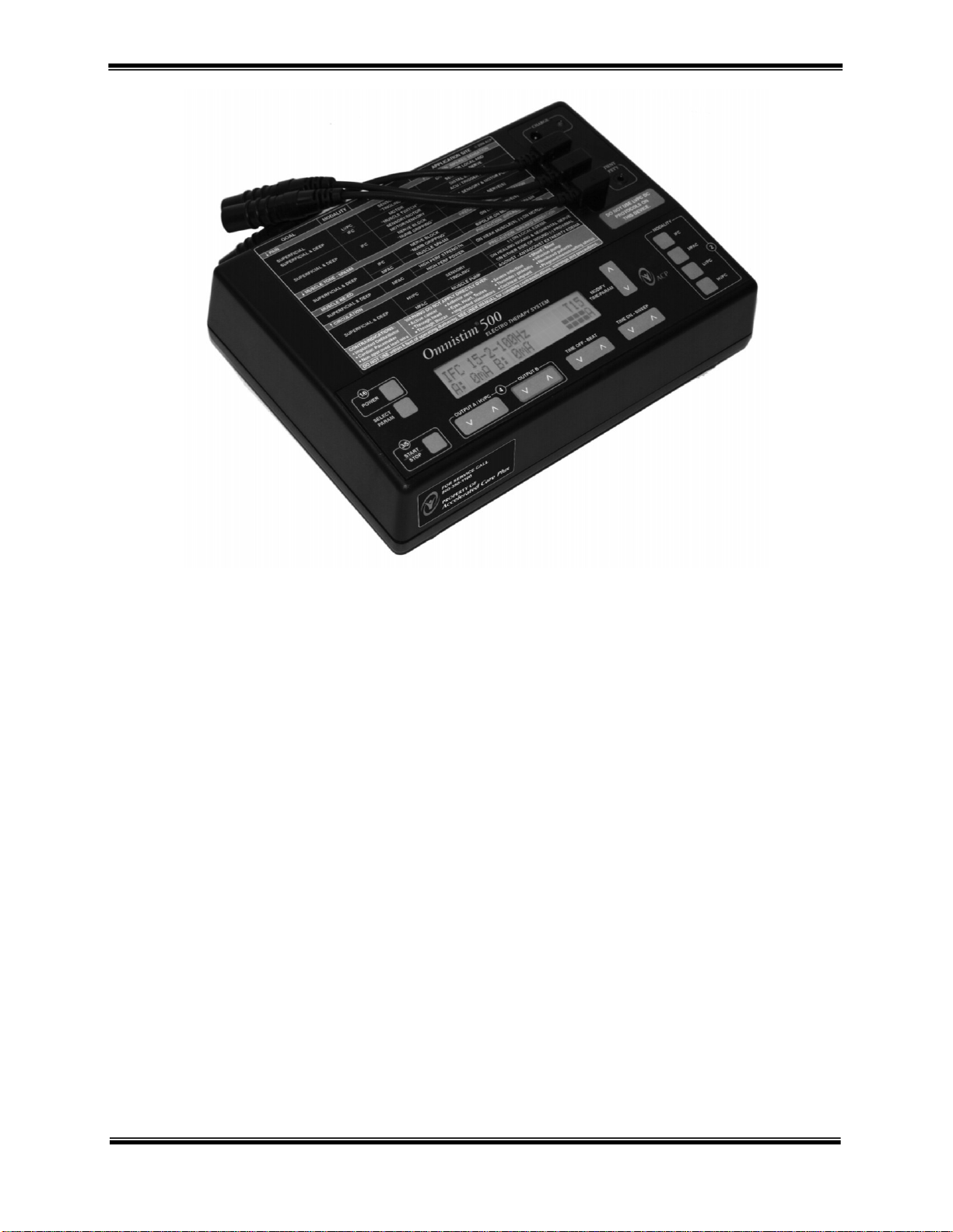
THE OMNISTIM® 500
Delivery of the OMNISTIM® 500
Upon receipt of your OMNISTIM
damage. All ACP products are packaged carefully for rapid, safe delivery. We guarantee delivery in perfect
condition to the postal or delivery services. However any damage or loss incurred during transportation or delivery
is the Postal or Delivery Company’s responsibility. If damage or loss to the product and/or container is obvious or
suspected, appropriate notation must be made on the signed freight bill at the time of delivery. All damage claims
should be promptly filed with the delivering carrier and must be initiated by the addressee where the package was to
be delivered. Retain the original shipping container and inserts for validation of damage claim or use at a later date.
Unpack and check all accessories. A list of enclosed accessories is provided with each unit to assist you in
identification of the type and number of accessories.
NOTE: The purpose of this manual is to acquaint you with the OMNISTIM® 500’s operating features and
functionality. Please read the manual carefully before attempting to operate the OMNISTIM
remain unanswered, contact your ACP sales representative or call 1-800-350-1100. Outside the USA call 1-775685-4000.
®
500, inspect the shipping container and contents for any obvious or concealed
®
500. If questions
Introduction
The OMNISTIM
Currents (MFAC), Low Voltage Pulsed Current (LVPC) and High Voltage Pulsed Current Therapy (HVPC). Its
two separate generators produce medium frequency (2000, 2500, 4000 or 5000 Hz) alternating current in continuous
or modulated modes. Two isolated output circuits with independent intensity controls are provided. The output of
each circuit is easily determined in milliamps through the display screen. The digital timer allows the operator to
select the length of the total treatment time and to monitor the time remaining in minutes.
The OMNISTIM
interferential vector scanning mode can be turned off or on for stationary or continuous movement of the
interferential field.
The OMNISTIM
provides a wide variety of uses for muscle re-education and muscle spasm reduction protocols for innervated
muscle.
The OMNISTIM
operation with fully adjustable ON and OFF times and ramps allow applications of HVPC therapy. Increasing
circulation, pain control and muscle re-ed can be set up in this mode.
®
500 is designed to provide Interferential Current Therapy (IFC), Medium Frequency Alternating
®
500 offers Frequency Difference (FD) and Full Field (FF) Interferential Current Therapy. An
®
500 MFAC and LVPC modes with fully adjustable ON and OFF times and ON and OFF ramps
®
500 provides High Voltage Pulsed Current (HVPC) on one channel. Continuous or surged
COPYRIGHT 2001 - 2007, ACCELERATED CARE PLUS CORP., ALL RIGHTS RESERVED
CONFIDENTIAL AND PROPRIETARY
Page 9
OMNISTIM® 500A USER MANUAL 9
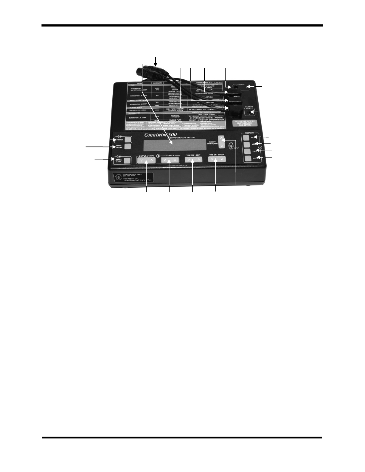
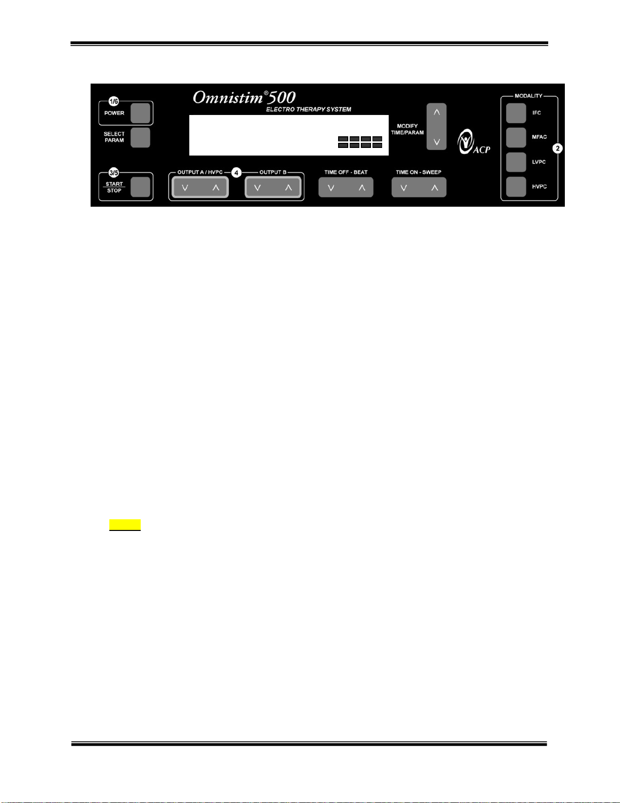
Controls and Functions
A. Main power switch. Press for power ON, press again for power OFF. The display illuminates with SELECT
MODALITY/PROGRAM.
B. Parameter select button provides adjustment of stimulation parameters, screen contrast, audio on/off and button
speed and sensitivity. Press to enter SETECT mode. It is possible to adjust most stimulation parameters at any
time during treatment.
C. START/STOP Set output button. Having selected the type of treatment and program press to set the output or
start or stop the treatment. START/STOP also cancels the SET mode.
D. Increase/Decrease OUTPUT A. Press rocker switch to the right to increase output current. Press to the left to
decrease output current.
E. Increase/Decrease OUTPUT B. Press rocker switch to the right to increase output current. Press to the left to
decrease output current.
F. Increase/Decrease Beat frequency or TIME OFF Press rocker switch to the right to increase the duration of the
TIME OFF period; press to the left to decrease the duration of the TIME OFF period during MFAC, LVPC or
HVPC modes. Press rocker switch to the right to increase BEAT (or base) frequency; press to the left to
decrease BEAT frequency during INTERFERENTIAL modes.
G. Increase/decrease SWEEP frequency or TIME ON. Press rocker switch to the right to increase duration of
TIME ON period; press to the left to decrease the duration of the TIME ON period during MFAC, LVPC or
HVPC modes. Press rocker switch to the right to increase SWEEP (or spectrum) frequency; press to the left to
decrease SWEEP frequency during INTERFERENTIAL mode.
H. Timer/parameter switch. Increases/decreases treatment time or changes parameters in set mode.
I. Select single channel HVPC protocol when pressed.
J. Selects LVPC protocol when pressed.
K. Selects MFAC (Russian style stimulation) protocol when pressed.
L. Select Interferential (IFC) protocol mode.
M. Patient Safety Input Switch
N. Charging/line operation indicator LED.
O. Battery charger input jack.
P. Output for HVPC.
A
B
C
S
T
D
Q
R
E
P
F
O
N
M
L
K
J
I
G
H
COPYRIGHT 2001 - 2007, ACCELERATED CARE PLUS CORP., ALL RIGHTS RESERVED
CONFIDENTIAL AND PROPRIETARY
Page 10

10 OMNISTIM
®
500A USER MANUAL
Q. Output for channel “B” in IFC, MFAC and LVPC modes.
R. Output for channel “A” in IFC, MFAC and LVPC modes.
S. Lead wire adapter – 3 pin.
T. Super twist LCD graphics display for all functions and parameters. The graphics screen allows display of:
• Modality selected
• Program selected
• Time remaining
• Bar graph for timing
• On-Off time, delay and ramps
• Beat frequency and sweep ranges
• Sweep rate and modulation selection
• Burst or pulse frequency
• Phase duration and interphase interval
• Output voltage or current
• Vector selection
• Battery condition
• Display contrast
• Button speeds and delay
Factory Settings
The OMNISTIM
These are generally suitable for most clinicians. To adjust these default settings proceed as follows:
1. When the main screen comes up and states “SELECT MODALITY/PROGRAM” push the SELECT
PARAMETERS button repeatedly to display the factory settings. You will then be able to adjust the
selected factory settings by pressing the TIME/PARAMETER up/down button. The new settings will be
saved from use to use as long as you do not remove the batteries or allow a full discharge of the unit.
®
500 comes with the following factory settings:
Button Speed, A & B Output 87
Button Speed, Beat, etc. 93
Button Delay, all 40
Audio ON
Screen Contrast 5
2. The screen contrast sets the appropriate viewing angle for easy screen legibility.
3. The button speed for output A & B sets the speed at which output will increase and decrease when you
push the buttons. This should generally be set at a slower speed (80 - 90) so as not to startle the patient.
4. The Button speed BEAT Etc. controls the scrolling speed of all of the remaining buttons on the system. A
speed of 90 to 95 is typical if you have good coordination and hand control.
5. The button delay represents the amount of time that you have to push and hold the buttons down before
they will begin to increment automatically at the button speed. The smaller the number the faster the
response time.
6. Audio on or off disables or enables the audio system that beeps at the end of the treatment and during the
NMES programs.
NOTE: The factory settings cannot be accessed during operation and are only available following the start
up screen. The settings will reset to their initial d efault parameters if the ba tteries are removed or the unit
is fully discharged. To restore the new settings follow the procedure in Appendix I.
COPYRIGHT 2001 - 2007, ACCELERATED CARE PLUS CORP., ALL RIGHTS RESERVED
CONFIDENTIAL AND PROPRIETARY
Page 11

OMNISTIM® 500A USER MANUAL 11
Battery Charger / Power Supply Operation
Before using the OMNISTIM
1. Verify that rechargeable batteries are installed within the OMNISTIM
2. Check to see that the battery type selector switch located inside the battery compartment has been switched
to the rechargeable position.
If you plug in the charger, after two seconds, the charge LED on the OMNISTIM
batteries are fully charged, the LED blinks. If you plug in the charger during treatment or when the unit is ON the
LED turns off. (The charging continues but at a trickle and does not cause the LED to glow.) When you turn OFF
the unit after two seconds the LED comes on to announce charging.
NOTE: If non-rechargeable batteries are used:
1. Do not use the charger.
2. Make sure that the rechargeable/non-rechargeable selector switch in the bottom of the battery
compartment is in the non-rechargeable position.
Life expectancies of batteries under nominal (20 mA IFC, 40 mA MFAC, 100v HVPC) load conditions:
• 4.4Ah NiCad rechargeable batteries - 10 Hours.
• Alkaline non-rechargeable batteries - 100 Hours.
®
500 battery charger/power supply:
®
500 battery compartment.
®
500 is illuminated. After the
COPYRIGHT 2001 - 2007, ACCELERATED CARE PLUS CORP., ALL RIGHTS RESERVED
CONFIDENTIAL AND PROPRIETARY
Page 12
12 OMNISTIM
Operational Sequence
SET OUTPUT A/B
A:00 mA B:00 mA r2.0
®
500A USER MANUAL
1. Press the ON/OFF button to turn on the power. The display panel will illuminate. There will be no
stimulation current and the unit will be in the SELECT MODALITY/PROGRAM mode.
2. At this time select the treatment modality desired and the appropriate treatment protocol by using the
modality buttons (2) to select HVPC, LVPC, MFAC or IFC protocols.
3. Now position the electrodes on the patient, connect the electrode plug(s) and press the START/STOP
button (3/5). The program parameters will disappear and be replaced with the screen seen above.
The bar graph on the lower right of the display shows the relative outputs of the two channels primarily
with respect to Time On and Time Off and Vector operation. The numeric displays on the lower left show
the output intensities into a 500-ohm load. Each time a treatment is commenced, the output current level is
reset to zero; this ensures that your patient cannot receive an initial shock due to the current output,
inadvertently, being left at a high setting from a previous treatment. The patient safety switch is a remote
duplicate of the Start/Stop switch and therefore resets the outputs to zero.
4. Adjust output by pressing the up/down (4) for channel A and channel B. Once desired output intensity is
selected, press START/STOP button (3/5) to display timer and to initiate treatment.
5. Press the SELECT PARAMETERS button to modify any settings. Press the MODIFY TIME / PARAM up or
down buttons to adjust the desired treatment time, or other settings, if you wish to change from the default
settings. Set the timer for the desired treatment time. Pressing the switch up or down, increases or decreases the
duration from a minimum of 1 minute to a maximum of 60 minutes. The timer will count down to zero during
treatment; when zero is reached a warning tone is emitted from the unit, the treatment current is switched off and
Treatment Off is displayed. Pressing the START/STOP button (3/5) will shut off the warning tone. If the unit is
left unattended, the warning tone is emitted for ten seconds before power is automatically switched off. Note that
the treatment time is preset for each program but may be adjusted at will during the treatment.
NOTE: When selecting the MFAC or LVPC alternate or delayed modes the system will allow first set up of
output A followed by set up of output B. Pushing the START/STOP SET output again will start the u nit
timing cycles if applicable in the program.
6. During operation the parameters may be altered within the program at will by selecting the set mode. See
set mode operation and adjustable parameters for each modality.
7. Once the treatment is completed, remove the electrodes from the patient and disconnect the lead wires from
the electrodes.
8. Turn the unit off by pressing the power button.
COPYRIGHT 2001 - 2007, ACCELERATED CARE PLUS CORP., ALL RIGHTS RESERVED
CONFIDENTIAL AND PROPRIETARY
Page 13
OMNISTIM® 500A USER MANUAL 13
TREATMENT GUIDELINES
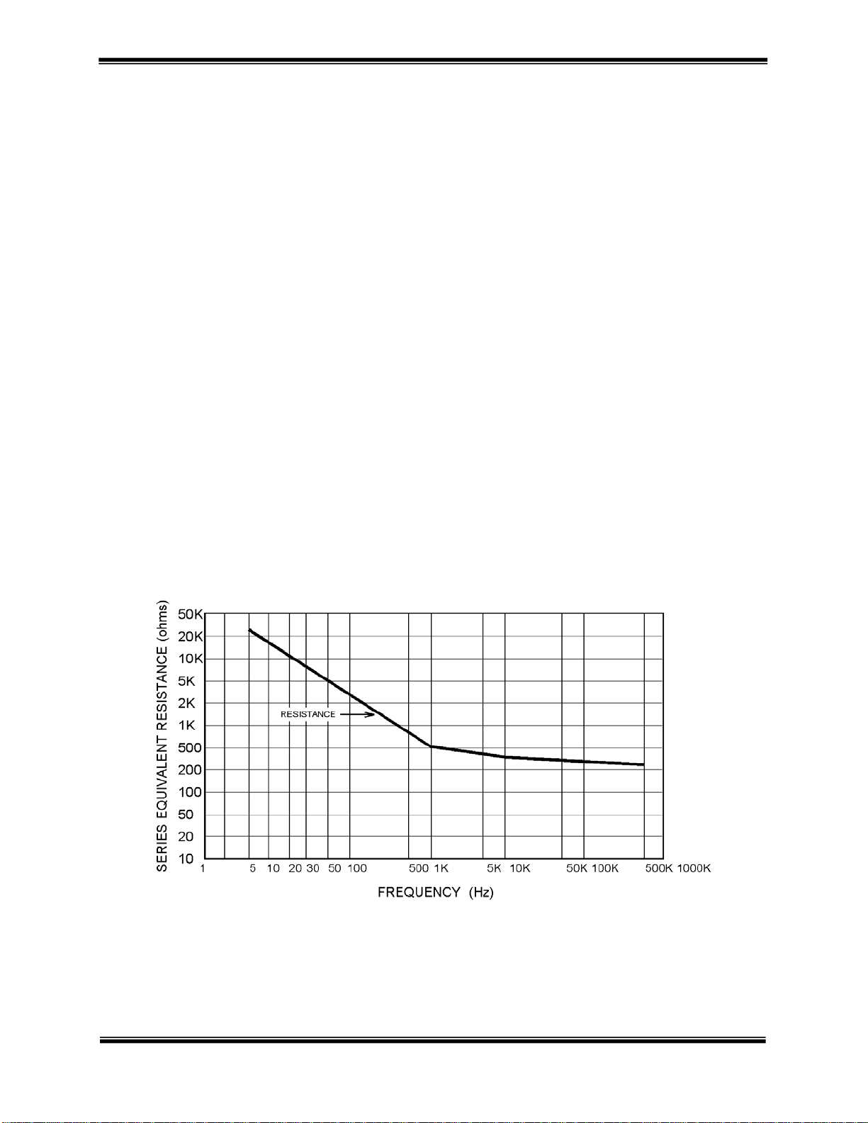
Introduction to Medium Frequency Currents
Medium frequency (MF) currents may be described as electrical currents applied to the body for therapeutic
purposes, which fall in the range of 1000 to 10,000 cycles per second (Hz). This is in contrast to low frequency
currents (0.1 to 1000 Hz) such as LVPC, HVPC, and high frequency currents (1 million Hz and beyond), which
include ultrasound, shortwave and microwave diathermy. Medium frequency currents are very advantageous for
clinical use due to their ease of skin penetration at lower intensities.
Normal human skin reacts differently to different frequencies of current. Specifically, there is an inverse
relationship between the frequency of the applied current and the skin’s resistance to it. Medium frequency
alternating currents in the range of 1000 or 5000 Hz provide markedly lower resistance to penetration than low
frequency electrical stimulation commonly used in TENS, LVPC, and HVPC stimulation. Medium frequency
currents can be used in Bipolar or in Quadripolar Interferential mode for patient treatment.
With medium frequency currents, the energy of each individual pulse is low providing for stimulation of only one or
two neurons. Since the pulses are coming in very rapid succession, stimulation of surrounding neurons occurs prior
to completion of the previous neurons refractory period. This allows for asynchronous activation of individual
sensory neurons, mimicking the natural physiologic process of the intact nervous system. This is not the case with
low frequency stimulators (0.1 to 1000Hz), which are capable of only stimulus synchronous neural activation.
Medium frequency currents provide rapid analgesic effects. This occurs due to rapid depolarization of nonmyelinated pain-transmitting fibers, which block pain transmission, further contributing to high muscle contraction
capabilities. Additionally, medium frequency currents have been shown to alter the vascular dynamics affecting
local and possibly systemic blood flow to the muscle(s) being stimulated. The unique characteristics of medium
frequency currents, (higher percent duty cycle, higher average current intensity, and wider pulse widths), can
significantly increase blood flow by altering the metabolic activity of muscles.
PLOT IMPEDANCE AS A FUNCTION OF FREQUENCY USING EPIDUCTIVE SYSTEMS
COPYRIGHT 2001 - 2007, ACCELERATED CARE PLUS CORP., ALL RIGHTS RESERVED
CONFIDENTIAL AND PROPRIETARY
Page 14
14 OMNISTIM
®
500A USER MANUAL
Electrode Application Techniques
The following electrode placement diagrams are a theoretical representation of treatment set-ups using the
OMNISTIM
Electrode placement is dependent on the etiology of the condition.
Monopolar (Mono-Polar) Technique
This technique may use two electrodes of different sizes. The smaller, or “active” electrode can be positioned over
the segmental innervation or peripheral nerve path of the involved tissue, or over a distal location overlying any
muscle that is not an antagonist to the muscle being stimulated.
®
500. Monopolar, bipolar and quadripolar techniques are illustrated for various areas of the body.
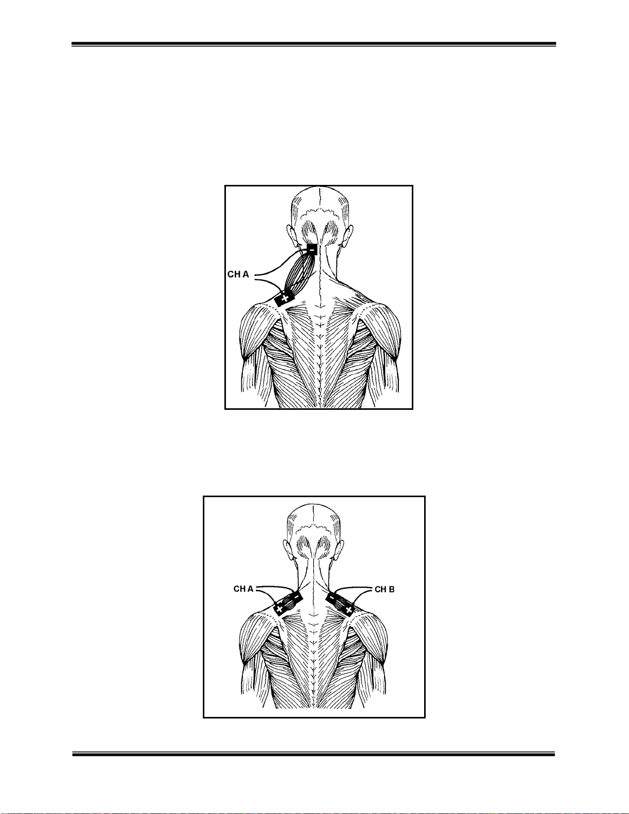
CERVICAL MONOPOLAR
PLACEMENT OF
ELECTRODES
Bipolar (Bi-Polar) Technique
This is the most commonly used technique for muscle stimulation. This technique utilizes two electrodes but not
exclusively of the same size. One electrode should be applied over the motor point and the other electrode over the
belly of the muscle as far away from the motor point as possible. This technique allows for more effective muscle
and nerve fiber recruitment since the entire neural innervation of the muscle is furnished with current.
CERVICAL BIPOLAR
PLACEMENT OF
ELECTRODES
COPYRIGHT 2001 - 2007, ACCELERATED CARE PLUS CORP., ALL RIGHTS RESERVED
CONFIDENTIAL AND PROPRIETARY
Page 15
OMNISTIM® 500A USER MANUAL 15
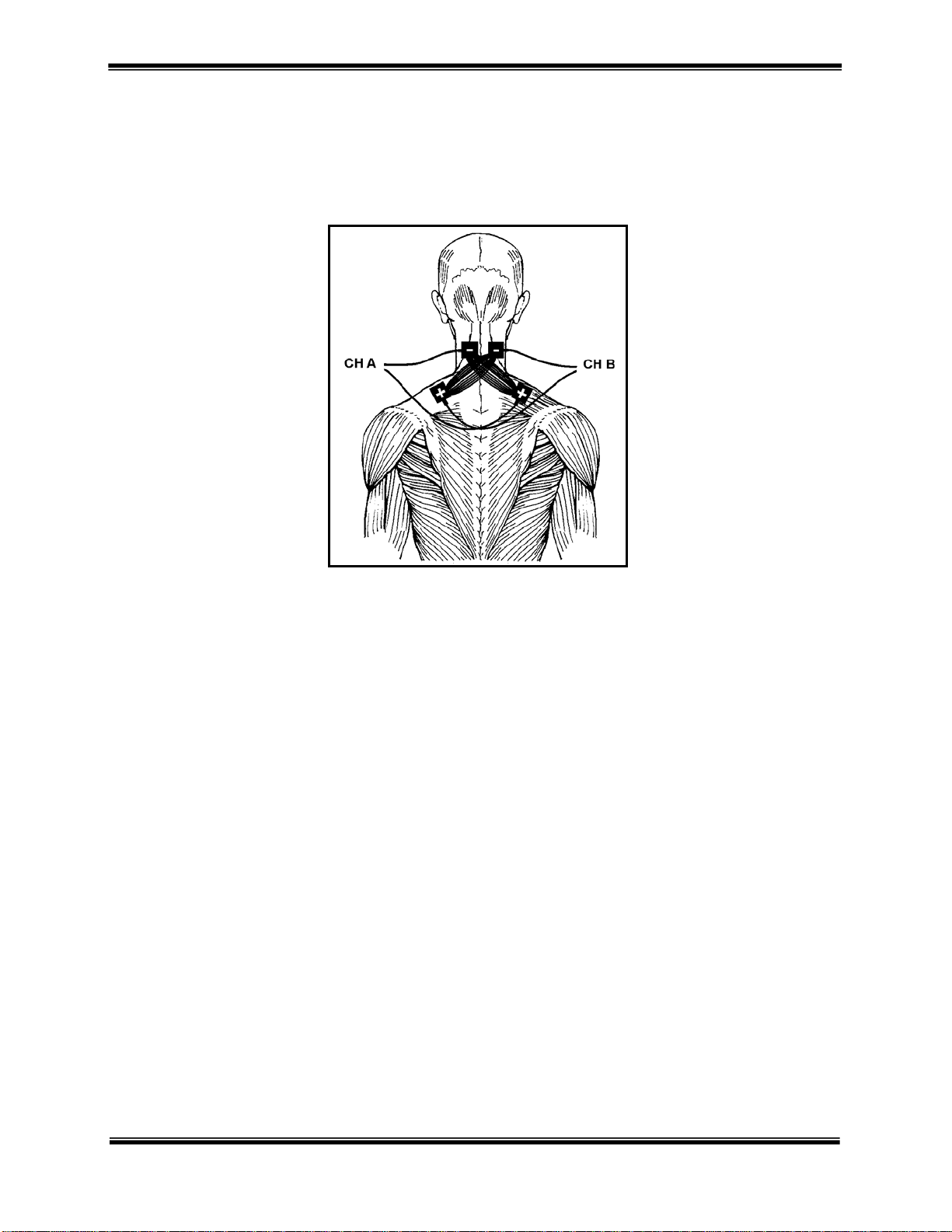
Quadripolar (Quadri-Polar) Technique
This technique requires the use of two output channels and four electrodes usually, but not exclusively of the same
size. The two electrodes from one channel are usually placed diagonally across the tissue area or joint to be treated
with the second channel electrodes placed on the opposite diagonal. This ensures that the current will intersect and
thus provide and interferential pattern.
CERVICAL QUADRIPOLAR
PLACEMENT OF
ELECTRODES
COPYRIGHT 2001 - 2007, ACCELERATED CARE PLUS CORP., ALL RIGHTS RESERVED
CONFIDENTIAL AND PROPRIETARY
Page 16

16 OMNISTIM
®
500A USER MANUAL
Treatment Preparation
Skin Inspection
Thoroughly cleanse the treated area with soap and water to remove oils, creams, dirt, and sweat; this will ensure
uniform current conduction across the skin. After cleansing, inspect and evaluate the skin’s integrity and sensation
prior to treatment. Avoid absent or diminished sensation; if unavoidable, treat with caution. Establishment of
acceptable intensity levels for desensitized areas may be related to the intensity levels tolerated on normal skin in
opposite or related body parts. Frequently monitor the intensity level and skin response during all treatments.
Stinging, burning or other painful sensation under the electrodes on normal or desensitized areas is an indication of
increased current density under part or all of the electrode surface. In this case, slowly but immediately reduce the
current intensity to zero; remove the electrodes to inspect the surface skin. Recheck your application techniques.
Immediately after treatment, clean and thoroughly inspect the skin under the electrode. Peripheral vasodilation along
with systemic vasomotor responses can lead to redness (hyperemia) directly under both electrodes. Inform the
patient of this normal after effect and that the redness will disappear within an hour or two. Apply topical agents to
the reddened area under the electrodes if needed to decrease post-treatment irritation. Persistent skin irritation could
be due to repeated stimulation of the same electrode site or a possible allergic reaction to the conductive mediums,
tapes, elastic wraps, and/or cleaning and disinfectant solutions. Therefore, use additional electrode stimulation sites
to decrease or eliminate skin irritation on electrically sensitive patients. If skin irritation persists with alternate site
applications, decrease the treatment times and lower the intensities; if necessary, discontinue treatment. If an
allergic reaction is suspected, attempt to identify and change the allergic substance(s). If skin irritation persists,
discontinue treatment until the source of irritation is determined.
By far the most common causes which lead to machines being incorrectly reported as faulty are inadequate or
improper conductive medium interface or lead wire breakage. Because of the increased current density available
with pulsed or continuous medium frequency currents, a proportionally greater degree of conductive medium
interface problems exists and should be monitored by the clinician.
ACP Reusable Electrodes
Remove the electrodes from their foil packaging. Cleanse the skin then apply the electrodes over the treatment site
points according to the electrode placements techniques described in this manual. Various sizes of electrodes are
available dependent upon muscle size of the area to be treated. Follow the enclosed infection control procedures.
Review the warnings and application directions on the electrode packaging.
NOTE: The use of conductive mediums other than specifically approved pre-gelled or self adhering electrodes such
as ultrasound gel or lotion, hand or body lotion, electrolyte spray mist, paper towels, non-approved reusable or
disposable pre-gelled or self-adhering electrodes—are contraindicated for use with OMNISTIM
Lead Wires
Inspect the full length of the lead wires for signs of frayed or cut wires and loose connections where the lead wires
join the stereo jack plug and tip pins. Insert the stereo plug completely. Allow the lead wires to hang freely with no
excessive strain on the stereo plug insulator.
Periodically check the lead wires by checking their conductivity with an Ohmmeter. With the lead wire pin tips
together, measure the resistance between the tip and ring conductors of the stereo plug. The resistance should
measure very near to zero. If the resistance remains near to zero when the pin tips are disconnected from each other,
a short exists in the stereo plug insulator; replace the lead wire set.
®
systems.
COPYRIGHT 2001 - 2007, ACCELERATED CARE PLUS CORP., ALL RIGHTS RESERVED
CONFIDENTIAL AND PROPRIETARY
Page 17

OMNISTIM® 500A USER MANUAL 17
INFECTION CONTROL EQUIPMENT AND PRINCIPLES OF USE
Definitions
• Barrier Film – One-time use, disposable plastic film for use over touch/operator surfaces of equipment to
reduce risks of cross-contamination and need for high level disinfection of equipment between patients.
• Germicidal Disposable Wipe – Low level and/or intermediate level disposable germicidal disinfectant
wipe for use on electrotherapeutic devices and accessories.
• Plastic Lead Wire Sleeve – Barrier to be used on electrical stimulation lead wires, covering the junction of
lead wire and electrode wire.
Universal Precautions – Body Substance Isolation
Universal Precautions (UP) must be implemented in the care of all patients to protect employees from occupational
exposure to bloodborne pathogens. Personal protective equipment (gloves, masks, gowns) should be available and
worn by staff when occupational exposure to blood, body fluids containing blood, semen and vaginal secretions is
likely to occur. Health care workers with exudating lesions or weeping dermatitis should refrain from all direct
patient care and from handling patient care equipment until the condition resolves. Equipment must be
cleaned/disinfected and protective barriers used when appropriate.
Cleaning/Disinfecting of the OMNISTIM® 500
Modality equipment shall be cleaned/disinfected per facility infection control policy. ACP recommends the
following guidelines:
Cleaning and Low Level Disinfection
This is a recommended daily housekeeping practice to keep the equipment clean and free of contaminants which
could contribute to transmission of infection. The following practices are recommended for use when treating intact
skin without the presence of physiologic fluids such as blood and urine.
• Clean equipment daily with ACP germicidal wipes. At the end of the day, wipe common contact surfaces,
such as control panel and lead wires, with germicidal disposable wipe and allow to air dry. This technique
will inactivate M. tuberculosis as well as most bacteria and viruses. This will also facilitate removal of
organic material contaminants from equipment.
• Disposable/reusable electrodes are for individual patient use only and should not be used on multiple patients.
Intermediate Level Disinfection and Barriers
This method is recommended to keep the equipment clean and free of contaminants when used between patients for
treatment of non-intact skin or incontinence management, where there is an increased risk of patient crosscontamination. The following are the recommended practices:
• After each use, clean common contact surfaces, such as control panel and lead wires with ACP germicidal
wipes.
• With a second ACP germicidal cloth, wipe again leaving surfaces wet for at least 5 minutes. Allow the
surface to air dry before patient use.
• Barriers should also be used on the equipment for treatment of non-intact skin or incontinence
management. This technique will inactivate M. tuberculosis as well as most bacteria and viruses.
COPYRIGHT 2001 - 2007, ACCELERATED CARE PLUS CORP., ALL RIGHTS RESERVED
CONFIDENTIAL AND PROPRIETARY
Page 18
18 OMNISTIM
®
500A USER MANUAL
Use of Barriers – Intermediate Level Disinfection
The use of an all-purpose barrier film provides surface protection from cross-contamination resulting from a variety
of applications. This procedure should be used whenever dealing with non-intact skin or the chance of coming in
contact with bodily fluids. Barrier film is designed to cover any surface that may be touched during a patient
treatment to help prevent cross-contamination. Barrier film is for single-use only. The film is discarded after each
patient treatment. The procedure for use is as follows:
1. Wash hands.
2. Apply intermediate level disinfection prior to barrier application.
3. Select, tear and place a length of barrier film to fit over the
operatory surfaces of the OMNISTIM
4. Select and cut with clean scissors a 2-foot length of plastic sleeve and fit
over the lead wire and the electrode cabling.
5. Prepare any items which may come in contatct with the therapist during
treatment, such as pens, assessment tools, cart handles, etc.
6. Set up the patient per guidelines for the procedure.
7. Provide treatment as appropriate.
8. Discard all disposables.
9. With clean gloves, remove the plastic film from the OMNISTIM
and discard.
10. Remove the plastic sleeve from the lead wire by sliding it toward the
electrode. Remove the electrode and discard with the sleeve.
11. Intermediate disinfect the OMNISTIM
treatment application.
®
500 unit.
®
500 unit prior to the next
®
500
COPYRIGHT 2001 - 2007, ACCELERATED CARE PLUS CORP., ALL RIGHTS RESERVED
CONFIDENTIAL AND PROPRIETARY
Page 19

®
PROTOCOL / CLINICAL
INDICATION
MODES OF OPERATON: Protocol Reference Sheets
Interferential Current (IFC)
STIMULATION PARAMETERS MECHANISM OF ACTION APPLICATION TECHNIQUE OPERATIONAL SEQUENCE
OMNISTIM
500A USER MANUAL 19
COPYRIGHT 2001 - 2007, ACCELERATED CARE PLUS CORP., ALL RIGHTS RESERVED
CONFIDENTIAL AND PROPRIETARY
ANALGESIA - SENSORY
SEGMENTAL SUB ACUTE
Symptomatic relief of pain from
localized dermatome or
segmental origin.
ANALGESIA - MOTOR
NON - SEGMENTAL CHRONIC
Symptomatic relief of pain with
inflammation, and pain of
generalized or multi-segmental
nature.
ANALGESIA / MOTORSENSORY
SUB-ACUTE CHRONIC
Symptomatic relief of pain with
inflammation, and pain of local,
generalized single or multisegmental nature.
ANALGESIA SENSORYMOTOR
ACUTE SUB-ACUTE
Symptomatic relief of pain with
Inflammation, pain of local,
generalized single or multisegmental nature.
• 5000Hz 80/120 BPS continuous
• Vector Fast 90
• Treatment time of 15 minutes
• 2500Hz – 2/6 BPS continuous
• Vector Fast 90
• Treatment time of 15 minutes
• 5000Hz – 15/2/100 BPS
• Vector Fast 90
• Treatment time of 30 minutes
• 5000Hz – 100/2 BPS continuous
• Vector Fast 90
• Treatment time of 30 minutes
o
o
o
o
Sensory stimulation activates A-beta fibers
causing the release of spinal Enkephalin and
Dynorphin to block pain at the segmental
level (Gate Control). Duration of relief is
typically from 30 min to 2 hrs. Fast onset of
relief usually within 20 minutes.
Motor level stimulation activates motor and
A-delta fibers causing the release of
Bendorphin systemically. Duration of relief is
typically from 2-6 hours. Slow Onset of relief
usually within 30 minutes to 1 hour
Combines motor and sensory stimulation.
Starts with motor and ends with sensory.
More aggressive protocol. Duration of relief
is typically from 2-6 hours. Slower onset of
relief usually within 30 minutes.
Combines sensory and motor stimulation.
Starts with sensory and ends with motor.
Less aggressive protocol. Duration of relief
is typically from 2-6 hours. Faster onset of
relief usually within 20 minutes.
Target tissue - superficial and deep. Bilateral,
bipolar or quadripolar through the painful area or
over the involved spinal segments. Apply parallel
to incision line for post op pain management. Set
intensity to elicit a pleasant tingling sensation, just
below muscle contraction.
Target tissue - superficial and deep. Bipolar
placement over local and distal acu / trigger
points; quadripolar placement over area of local
pain; or quadripolar placement at spinal segment.
Set intensity to elicit a moderate muscle twitch.
Target tissue - superficial and deep. Bipolar
placement over local and distal acu / trigger
points; quadripolar placement over area of local
pain; or quadripolar placement at spinal segment.
Set intensity to elicit a moderate muscle twitch.
Target tissue - superficial and deep. Bipolar
placement over local and distal acu / trigger
points; quadripolar placement over area of local
pain; or quadripolar placement at spinal segment.
Set intensity to elicit a strong tingling sensation
just under muscle contraction.
• Press IFC button until screen reads "ANALGESIA - SENSORY"
• Press START / STOP until screen reads " SET OUTPUTS A-B"
• Set Outputs A and B until the patient feels the desired sensation.
• Press START / STOP and T15 will display in upper right corner.
• Adjust treatment time if necessary using the TIME/PARAMETER button
• The treatment will end at the end of the preset time or if the patient safety
switch is pressed.
• Press IFC button until screen reads "ANALGESIA - MOTOR"
• Press START / STOP until screen reads " SET OUTPUTS A-B"
• Set Outputs A and B until the patient feels the desired sensation.
• Press START / STOP and T15 will display in upper right corner.
• Adjust treatment time if necessary using the TIME/PARAMETER button
• The treatment will end at the end of the preset time or if the patient safety
switch is pressed.
• Press IFC button until screen reads "ANALGESIA/MOTOR - SENSORY"
• Press START / STOP until screen reads " SET OUTPUTS A-B"
• Set Outputs A and B until the patient feels the desired sensation.
• Press START / STOP and T30 will display in upper right corner.
• Adjust treatment time if necessary using the TIME/PARAMETER button
• The treatment will end at the end of the preset time or if the patient safety
switch is pressed.
• Press IFC button until screen reads "ANALGESIA/SENSORY - MOTOR"
• Press START / STOP until screen reads " SET OUTPUTS A-B"
• Set Outputs A and B until the patient feels the desired sensation.
• Press START / STOP and T30 will display in upper right corner.
• Adjust treatment time if necessary using the TIME/PARAMETER button
• The treatment will end at the end of the preset time or if the patient safety
switch is pressed.
ANALGESIA NERVE
BLOCK
LOCAL ACUTE
Symptomatic relief of pain from
localized dermal or segmental
origin.
• 5000Hz Continuous
• Vector OFF
• Treatment time of 10 minutes
Blocks pain by causing a temporary nerve
block through reactive depolarization
(Conduction block) of the pain signal on its
way to the spinal input. Also known as
Wedensky inhibition. Duration of relief is
typically from 1-2 hours Faster onset of relief
usually within 5-10 minutes.
Target tissue - superficial and deep. Bipolar
placement over local nerve; quadripolar placement
over area of local pain; quadripolar placement at
spinal segment. Set intensity to a numb-gripping
sensation just under muscle contraction.
• Press IFC button until screen reads "ANALGESIA NERVE BLOCK"
• Press START / STOP until screen reads " SET OUTPUTS A-B"
• Set Outputs A and B until the patient feels the desired sensation.
• Press START / STOP and T10 will display in upper right corner.
• Adjust treatment time if necessary using the TIME/PARAMETER button
• The treatment will end at the end of the preset time or if the patient safety
switch is pressed.
Page 20

®
COPYRIGHT 2001 - 2007, ACCELERATED CARE PLUS CORP., ALL RIGHTS RESERVED
CONFIDENTIAL AND PROPRIETARY
PROTOCOL / CLINICAL
INDICATION
NMES EDEMA-MUSCLE
PUMP
Increase circulation, venous and
lymphatic return through muscle
pump.
NMES - MUSCLE SPASM
Relaxation of muscle spasm.
HI PERFORMANCE MFAC
RE-ED STRENGTH
Treatment of muscle disuse
atrophy for strength
development.
HI PERFORMANCE MFAC
RE-ED POWER
Treatment of muscle disuse
atrophy for power development.
NMES - SEQ RE-ED
Activates muscles sequentially
to simulate functional movement
or firing patterns.
SPASTICITY REDUCTION
RECIPROCAL INHIBITION
Reduces muscle tone (Spasm)
of spastic muscle.
Medium Frequency Alternating Current (MFAC)
STIMULATION PARAMETERS MECHANISM OF ACTION APPLICATION TECHNIQUE OPERATIONAL SEQUENCE
• Press MFAC until screen reads "NMES EDEMA-MUSCLE PUMP"
• Press START / STOP until screen reads " SET OUTPUT A"
• 5000Hz - 35 BPS
• 4 Sec “ON” time and 12 Sec “OFF” time
• Reciprocal (alternating) timing pattern
• Ramps 2 Sec “ON/OFF”
• Treatment time of 15 minutes
• 5000 Hz - 80 BPS
• 10Sec “ON” time and 10Sec “OFF” time
• Channels fire simultaneously
• Ramps are set for 3 Sec “ON/OFF”
• Treatment time of 15 minutes
• 2500Hz – 75 BPS
• 10Sec “ON” time and 50Sec “OFF” time
• Channels fire simultaneously
• Ramps are set for 2 Sec “ON/OFF”
• Treatment time of 10 minutes.
• 2500Hz - 70 BPS
• 10Sec “ON” time and 50Sec “OFF” time
• Channels fire simultaneously
• Ramps are set for .2 Sec “ON” and 1
Sec “OFF”
• Treatment time of 10 minutes
• 2500Hz - 70 BPS
• 10Sec “ON” time and 50Sec “OFF” time
• Channels fire sequentially with a .2 Sec
delay
• Ramps are set for 2 Sec “ON/OFF”
• Treatment time of 15 minutes
• 5000 Hz - 80 BPS
• 2500Hz - 50 BPS
• 12Sec “ON” time and 18Sec “OFF” time
• Channels fire simultaneously
• Ramps are set for 6 Sec “ON” and 2
Sec “OFF”
• Treatment time of 20 minutes
Activation of muscle causing contraction of
the agonist and antagonist to move the joint.
The muscle pump action compresses fluids
into the venous and lymphatic return, while
improving blood flow to the edematous
tissue.
Activation of muscle with electrical
stimulation with a 1:1 ratio of on/off times
causes muscle fatigue reducing muscle
spasm. Sensory stimulation of the muscles
also reduces pain and thus reflex muscle
spasm.
Activation of muscle with electrical
stimulation at a high intensity for a short time
with long on/off ramps reduces atrophy and
improves strength The patient should
participate to the extent possible by
contracting during the stimulation on time.
Activation of muscle with electrical
stimulation at a high intensity for a short time
with short “ON/OFF” ramps reduces atrophy
and improves power. The patient should
participate to the extent possible by
contracting during the stimulation on time.
Activation of muscle causing contraction of
the muscles in a sequential manner. May be
used to retrain functional activity and reduce
disuse atrophy in activities such as gait
training for activation of swing phase to heel
strike.
Stimulation of the spastic muscle's
antagonists activates reciprocal inhibition of
the spastic muscle reducing tone. Slow
ramps decrease the potential to trigger
spasticity of the agonist. Duration of relief is
typically from 2-3 hours.
Target tissue - superficial and deep muscle groups
and large joints. Bipolar set-up over agonist and
antagonist muscles for target joint. Set intensity to
elicit muscle contraction causing pain free joint
movement typically a grade 3-4 muscle
contraction. Reduce treatment time based on
muscle fatigue.
Target tissue - superficial and deep muscle
groups. Bipolar set-up over agonist and antagonist
muscles for target muscle. Set intensity to elicit a
grade 2-3 muscle contraction.
Target tissue - larger superficial and deep muscle
groups Bipolar set-up over agonist and antagonist
muscles for target muscle. Set intensity to elicit a
grade 3-5 muscle contraction. Reduce treatment
time based on muscle fatigue. Restrict joint
movement by holding manually, or using weights
or exercise bands.
Target tissue - larger superficial and deep muscle
groups. Bipolar set-up over the muscles to be
sequentially stimulated. Ch A fires first followed by Ch
B. The delay and ramps may be adjusted using th e set
parameter functions to simulate the desired fu nctional
pattern. Set intensity to elicit a grade 3-5 muscle
contraction. Reduce treatment time based on muscle
fatigue. Restrict joint movement by holding manuall y,
or using weights or exercise bands.
A single channel (A or B) is used over the spastic
muscle's antagonist. Set intensity to elicit a
grade2-3 muscle contraction. Ensure the intensity
is not too high to induce overflow activation of the
spastic muscle. Reduce treatment time based on
muscle fatigue and inhibition of spasticity.
• Set Output A until the desired contraction of the Ch A muscle group is
obtained.
• Press START / STOP until screen reads " SET OUTPUT B"
• Set Output B until the desired contraction of the Ch B muscle group is
obtained.
• Press START / STOP and T15 will display in upper right corner.
• Adjust treatment time if necessary using the TIME/PARAMETER button
• The treatment will end at the end of the preset time or if the patient safety
switch is pressed.
• Press MFAC until screen reads "NMES - MUSCLE SPASM"
• Press START / STOP until screen reads " SET OUTPUTS A-B"
• Set Outputs A and B until the desired contraction level is obtained
• Press START / STOP and T15 will display in upper right corner.
• Adjust treatment time if necessary using the TIME/PARAMETER button
• The treatment will end at the end of the preset time or if the patient safety
switch is pressed.
• Press MFAC until screen reads "HI PERFORMANCE MFAC RE-ED
STRENGTH"
• Press START / STOP until screen reads " SET OUTPUTS A-B"
• Set Outputs A and B until the desired contraction level is obtained
• Press START / STOP and T10 will display in upper right corner.
• Adjust treatment time if necessary using the TIME/PARAMETER button
• The treatment will end at the end of the preset time or if the patient safety
switch is pressed.
• Press MFAC until screen reads "HI PERFORMANCE MFAC RE-ED
POWER"
• Press START / STOP until screen reads " SET OUTPUTS A-B"
• Set Outputs A and B until the desired contraction level is obtained
• Press START / STOP and T10 will display in upper right corner.
• Adjust treatment time if necessary using the TIME/PARAMETER button
• The treatment will end at the end of the preset time or if the patient safety
switch is pressed.
• Press MFAC until screen reads "NMES - SEQ RE-ED"
• Press START / STOP until screen reads " SET OUTPUTS A-B"
• Set Outputs A and B until the desired contraction level is obtained
• Press START / STOP and T15 will display in upper right corner.
• Adjust treatment time if necessary using the TIME/PARAMETER button
• The treatment will end at the end of the preset time or if the patient safety
switch is pressed.
• Press MFAC until screen reads "SPASTICITY REDUCTION RECIPROCAL
INHIBITION "
• Press START / STOP until screen reads " SET OUTPUTS A-B"
• Set Outputs A and B until the desired contraction level is obtained
• Press START / STOP and T20 will display in upper right corner.
• Adjust treatment time if necessary using the TIME/PARAMETER button
• The treatment will end at the end of the preset time or if the patient safety
switch is pressed.
20 OMNISTIM
500A USER MANUAL
Page 21

®
COPYRIGHT 2001 - 2007, ACCELERATED CARE PLUS CORP., ALL RIGHTS RESERVED
CONFIDENTIAL AND PROPRIETARY
PROTOCOL / CLINICAL
INDICATION
ANALGESIA SENSORY
Symptomatic relief of pain
from localized dermatome or
segmental origin. Increase
circulation.
ANALGESIA MOTOR
Symptomatic relief of pain
with inflammation, or pain of
a generalized or multisegmental nature.
NMES - R.O.M.
To provide estim assisted
passive or active assisted
R.O.M. at a joint.
NMES RE-ED
Treatment of muscle disuse
atrophy
for strength development.
NMES RE-ED
ENDURANCE
Treatment of muscle disuse
atrophy for endurance
development.
DENERVATED MUSCLE
D.C.
Low Volt Pulsed Current (LVPC)
STIMULATION PARAMETERS MECHANISM OF ACTION APPLICATION TECHNIQUE OPERATIONAL SEQUENCE
• Press LVPC button until screen reads "ANALGESIA SENSORY".
• Press START / STOP until screen reads “SET OUTPUTS A-B".
• Set Outputs A and B until the patient feels the desired sensation.
• Press START / STOP and T20 will display in upper right corner.
• Adjust treatment time if necessary using the TIME/PARAMETER
button.
• The treatment will end at the end of the preset time or if the patient
safety switch is pressed.
• Press LVPC button until screen reads "ANALGESIA MOTOR".
• Press START / STOP until screen reads “SET OUTPUTS A-B".
• Set Outputs A and B until the patient feels the desired sensation.
• Press START / STOP and T20 will display in upper right corner.
• Adjust treatment time if necessary using the TIME/PARAMETER
button.
• The treatment will end at the end of the preset time or if the patient
safety switch is pressed.
• Press LVPC until screen reads "NMES - R.O.M."
• Press START / STOP until screen reads “SET OUTPUTS A-B".
• Set Outputs A and/or B until the desired contraction level is obtained.
• Press START / STOP and T30 will display in upper right corner.
• Adjust treatment time if necessary using the TIME/PARAMETER
button.
• The treatment will end at the end of the preset time or if the patient
safety switch is pressed.
• Press LVPC until screen reads "NMES RE-ED".
• Press START / STOP until screen reads “SET OUTPUTS A-B".
• Set Outputs A and/or B until the desired contraction level is obtained.
• Press START / STOP and T15 will display in upper right corner.
• Adjust treatment time if necessary using the TIME/PARAMETER
button.
• The treatment will end at the end of the preset time or if the patient
safety switch is pressed.
• Press LVPC until screen reads "NMES RE-ED ENDURANCE".
• Press START / STOP until screen reads "SET OUTPUTS A-B".
• Set Outputs A and/or B until the desired contraction level is obtained.
• Press START / STOP and T30 will display in upper right corner.
• Adjust treatment time if necessary using the TIME/PARAMETER
button.
• The treatment will end at the end of the preset time or if the patient
safety switch is pressed.
• Do not use this protocol.
• Protocol requires the use of a DC adapter which is no longer available
from ACP.
• 100Hz - 80uSec PD Continuous
• Treatment time of 20 minutes
• 4Hz - 250uSec PD Continuous
• Treatment time of 20 minutes
• 35Hz - 200uSec PD
• 4 Sec “ON” time and 12 Sec “OFF” time
• Simultaneous timing pattern
• Ramps are set for 2 Sec “ON/OFF”
• Treatment time of 30 minutes
• 50Hz - 200uSec PD
• 10 Sec “ON” time and 50 Sec “OFF” time
• Channels fire simultaneously
• Ramps are set for 2 Sec “ON/OFF”
• Treatment time of 15 minutes
• 10Hz - 200uSec PD
• 5 Sec “ON” time and 30 Sec “OFF” time
• Channels fire simultaneously
• Ramps are set for 1 Sec “ON/OFF”
• Treatment time of 30 minutes
No longer used
Sensory stimulation reduces pain through
segmental release of Enkephalin and Dynorphin
(Gate Control). It also activates local vasodilation
increasing local circulation. Application of
negative polarity over the edematous site has
been demonstrated to reduce post-traumatic
edema in clinical trials.
Motor level stimulation activates motor and A-delta
fibers causing the release of Bendorphin
systemically Duration of relief is typically from 2-6
hours Slow Onset of relief usually within 30
minutes to 1 hour.
Activation of muscle causing contraction of the
agonist and antagonist to move the joint and
improve the R.O.M. Reduce treatment time based
on muscle fatigue.
Activation of muscle with electrical stimulation at a
high intensity for a short time reduces disuse
atrophy and improves strength and power. The
patient should participate to the extent possible by
contracting during the stimulation “ON” time.
Reduce treatment time based on muscle fatigue.
Activation of muscle with electrical stimulation at
lower intensity for a longer time reduces disuse
atrophy and improves endurance. The patient
should participate to the extent possible by
contracting during the stimulation "ON" time.
Reduce treatment time based on muscle fatigue.
Intentionally left blank
Target tissue-superficial. Bilateral bipolar through
the painful area or over the involved spinal
segments. Apply parallel to incision line for post-op
pain management. Set intensity to elicit a pleasant
tingling sensation, just below muscle contraction.
Target tissue-superficial. Bipolar placement over
local and distal acu / trigger point or at spinal
segmental level. Set intensity to elicit a motor
twitch.
Target tissue - smaller superficial muscle groups.
Bipolar set-up over agonist muscle for targeted
joint. Set intensity to elicit muscle contraction
causing pain free joint movement typically a grade
3-4 muscle contraction.
Target tissue - smaller superficial muscle groups.
Bipolar set-up over agonist and antagonist muscl es.
Set intensity to elicit a grade 3-5 muscle contraction.
Reduce treatment time based on muscle fatigue.
Restrict joint movement by holding manually, or usi ng
weights or exercise bands.
Target tissue - smaller superficial muscle groups.
Bipolar set-up over agonist and antagonist muscles for
target muscle. Set intensity to elicit a grade 2-4 muscle
contraction. Reduce treatment time based on muscle
fatigue. Restrict joint movement by holding manuall y, or
using weights or exercise bands.
Intentionally left blank
OMNISTIM
500A USER MANUAL 21
• Do not use this protocol.
LOW INTENSITY D.C.
No longer used
Intentionally left blank
Intentionally left blank
• Protocol requires the use of a DC adapter which is no longer available
from ACP.
Page 22

®
COPYRIGHT 2001 - 2007, ACCELERATED CARE PLUS CORP., ALL RIGHTS RESERVED
CONFIDENTIAL AND PROPRIETARY
PROTOCOL / CLINICA L
INDICATION
HVPC SENSORY
Symptomatic relief of pain
from localized dermatome or
segmental origin Increase
circulation. Increase
circulation.
EDEMA-MUSCLE PUMP
Increase circulation, venous
and
lymphatic return through
muscle pump.
High Volt Pulsed Current (HVPC)
STIMULATION PARAMETERS MECHANISM OF ACTION APPLICATION TECHNIQUE OPERATIONAL SEQUENCE
• Press HVPC until screen reads "HVPC SENSORY"
• Press START / STOP until screen reads " SET OUTPUT A
INTENSITY"
• Set Output A/HVPC unt il the patient feels the desired sensation.
• Press START / STOP and T20 will display in upper right corner.
• Adjust treatment time if necessary using the TIME/PARAMETER button
• The tr eatment will end at the end of the preset time or if the patient
safety switch is pressed.
• Press HVPC until screen reads "EDEMA - MUSCLE PUMP"
• Press START / STOP until screen reads " SET OUTPUT A
INTENSITY"
• Set Output A/HVPC until the desired contraction level is obtained
• Press START / STOP and T20 will display in upper right corner.
• Adjust treatment time if necessary using the TIME/PARAMETER button
• The treatment will end at the end of the preset time or if the patient
safety switch is pressed.
• 125Hz + or – Polarity Continuous
• Treatment time of 20-45 minutes
• 50Hz + or – Polarity
• 4 Sec “ON” time 12 Sec “OFF” time
• Single channel only (A)
• Ramps 2 Sec “ON/OFF”
• Treatment time of 20 minutes
Sensory stimulation reduces pain through
segmental release of Enkephalin and Dynorphin
(Gate Control). It also activates local vasodilation
increasing local circulation. Application of negative
polarity over the edematous site has been
demonstrated to reduce post-traumatic edema in
clinical trials.
Activation of muscle causing contraction of the
agonist to move the joint. The muscle pump action
compresses fluids into the venous and lymphatic
return, while improving blood flow to the
edematous tissue. Reduce treatment time based
on muscle fatigue.
Target tissue - superficial and deep. Bipolar,
appropriate polarity through the target tissue return
electrode at spinal segmental electrode or local
nerve. Set intensity to elicit a pleasant tingling
sensation, just below the muscle contraction.
Target tissue - superficial and deep muscle groups
and joints. Bipolar set-up over agonist muscle for
target joint or edematous tissue. Set intensity to
elicit muscle contraction causing pain free joint
movement typically a grade 3-4 muscle
contraction.
22 OMNISTIM
500A USER MANUAL
Page 23

OMNISTIM® 500A USER MANUAL 23
STIMULATION THERAPY MODES
Interferential Current Therapy (IFC)
The new Webster Encyclopedia Dictionary of the English Language defines interference as “the mutual action of
waves of any kind (water, sound, heat or light) upon each other, by which the vibrations and their effects are
increased, diminished or neutralized.”
As such, interferential current (IFC) therapy requires at least two signal sources, which “interfere” within the tissue
to be treated. The resulting interference of the generators generates therapeutically useful stimulation of the area
undergoing treatment. Interferential current therapy technique relies on amplitude differences between two or more
isolated independent signals to produce fields of higher or lower intensity within the tissue.
The purpose of interferential current therapy is to provide deep tissue treatment, which is not generally obtainable
with conventional electrotherapy approaches. Its primary application is in the reduction of pain and in the
stimulation of increased blood flow in the deeper tissues and muscles.
1. Frequency Difference (FD) Technique
Dr. Hans Nemec, an Austrian physician, first introduced the concept of frequency difference interferential current
therapy to the medical community in the late forties. The original U.S. patent (2,622,601) for the technique was filed
on October 27, 1948 and granted on December 23, 1952. It has since expired and many manufacturers worldwide
produce interferential current therapy devices according to Dr. Nemec’s original method.
Simply stated, electric currents with frequencies in the range of 1000-10,000 Hz, known as medium frequency
currents, are run through the tissue to be treated. These frequencies inhibit nerve conduction based on the fact that
they cause temporary nerve membrane depolarization while present. This effect is known as Wedensky Inhibition.
Medium frequency currents have an inhibitory effect on pain transmission and sensation within the field of
treatment. This effect is responsible for the decreased sensation under the stimulation electrodes. Medium
frequencies are also selected due to their excellent tissue penetration. This occurs as a result of the decreased tissue
resistance at higher frequencies.
If the frequencies of the two generators are not the same, then a beat frequency (which is the difference between the
two signal frequencies) is produced at right angles to the plane of the four stimulation electrodes. This beat
frequency modulates the medium frequency current to produce a burst medium frequency within the tissues.
The effects of frequency difference interferential current therapy may be described as follows:
a. Stimulation of deep tissue only with two fields.
b. Produces surface Nerve Block via Wedensky Inhibition (helpful in acute pain treatment).
2. Vector Technique
In order to move the position of the deep interferential fields, researchers developed systems to alter the relative
amplitudes between stimulation channels in interferential stimulators. This alteration of relative amplitude changes
the phase relationships and the position of the summated field in the tissue.
Advantages of Dynamic Vector:
1. When the patient expresses a poor pain location
and cannot indicate whether or not the therapy
feels the strongest at the subjectively perceived
location of the problem.
2. When the target tissue area is extremely large.
3. When you wish to increase the amount of current
density in the tissues to obtain a higher
therapeutic dosage.
4. When your electrode placement sites are less than
optimal.
COPYRIGHT 2001 - 2007, ACCELERATED CARE PLUS CORP., ALL RIGHTS RESERVED
CONFIDENTIAL AND PROPRIETARY
Page 24

24 OMNISTIM® 500A USER MANUAL
3. IFC FF-Full Field Mode:
The well-known attributes of modulated medium
frequency currents, i.e. deep tissue penetration,
asynchronous neural stimulation, and low tissue
resistance, allows the creation of an interferential
therapy system capable of both deep and
superficial stimulation with the goals of
maximizing sensory inputs. This technique is
referred to as full field interferential current
therapy. Full field amplitude summation
interferential current therapy relies on the
addition and subtraction of two intersecting
currents within the tissue. This effect is based on
the relative phase differences between the
currents at different positions in the field. The
following technique is used in the OMNISTIM
®
500 when in the full field mode of operation.
The highest intensity field is obtained in the deep
tissue at bisecting angles to the out-of-phase
electrodes. This technique offers three
stimulation fields.
Amplitude Summation - IFC Technique
Three zones of
stimulation
AMPLITUDE SUMMATION IFC TECHNIQUE
RATE SCAN ON OR OFF
2500 or 5000 Hz Pulsed at 100Hz
2500 or 5000 Hz
Pulsed at 100Hz
sensory
2500 or 5000 Hz Pulsed at 100Hz
Should the clinician desire rapid analgesia and maximum comfort in both the surface and deep tissues, continuous
non-modulated MF currents may be used with the OMNISTIM
®
, which will produce strong nerve blocks
(Wedensky Inhibition) throughout the entire treatment field. This is often useful in the mobilization of joints, prior
to transverse friction massage, or for relieving acute pain. It should be noted that this technique would produce only
transient relief of pain.
The effects of full field interferential current
therapy may be described as follows:
RATE SCAN ON OR OFF
2500 or 5000 Hz Pulsed at 100Hz
a. Stimulation of deep and surface
tissues.
2500 or 5000 Hz
b. May be used to produce deep and
surface analgesia via nerve block
(Wedensky Inhibition) when MF
mode is used.
4. Interferential Current Therapy IFC
Treatment Programs
The IFC mode contains five pre-programmed
modes and a custom program, which may be
programmed and saved by the user. The
custom program will remain as long as the
batteries remain charged or are not removed.
Three
zones of
Wedensky
Inhibition
All parameters other than the Carrier frequency
may be varied during operation. The following
programs are available in IFC mode:
FULL FIELD WEDENSKY INHIBITION
2500 or 5000 Hz
COPYRIGHT 2001 - 2007, ACCELERATED CARE PLUS CORP., ALL RIGHTS RESERVED
CONFIDENTIAL AND PROPRIETARY
Page 25

OMNISTIM® 500A USER MANUAL 25
ANALGESIA – SENSORY (FULL FIELD):
Target tissue is superficial and deep. Sensory stimulation activates A-beta fibers causing the release of spinal
Enkephalin and Dynorphin to block pain at the segmental level (Gate Control). Duration of relief is typically from
30 minutes to 2 hours. Fast onset of relief usually within 20 minutes.
PARAMETER DEFAULT VALUES
IFC Mode: Full Field
Carrier frequency: 5.0 KHz
Burst frequency: 100Hz .0 Hz to 999 Hz
Burst rate scan: 20% 0 – 50%
Burst scan time: 10 seconds 0 – 20 Seconds
Beat:
Sweep:
Rate Scan Time:
Rate scan: ON ON or OFF
Vector: Fast 90º
Auto Intensity: 10% 0 – 20%
Treatment time: 15 minutes 0 – 99 Minutes
Waveform: Alternating Current
Output: 0 mA 0 – 99 mA
RANGE OF USER
ADJUSTABLE VALUES
2.0 KHz, 2.5 KHz,
4.0 KHz 5.0 KHz
OFF, Fast 90º, Slow 90º,
Fast 45º, Slow 45º
ANALGESIA – SENSORY (FREQUENCY DIFFERENCE):
Target is deep tissue. Sensory stimulation activates A-beta fibers causing the release of spinal Enkephalin and
Dynorphin to block pain at the segmental level (Gate Control). Duration of relief is typically from 30 minutes to 2
hours. Fast onset of relief usually within 20 minutes.
PARAMETER DEFAULT VALUES
IFC Mode: Frequency Difference
Carrier frequency: 5.0 KHz
Burst frequency:
Burst rate scan:
Burst scan time:
Beat: 80 Hz .0 – 250 Hz
Sweep: 120 Hz .0 – 250 Hz
Rate Scan Time: 15 Seconds 0 – 20 Seconds
Rate scan:
Vector: Fast 90º
Auto Intensity: 0% 0 – 20%
Treatment time: 15 minutes 0 – 99 Minutes
Waveform: Alternating Current
Output: 0 mA 0 – 99 mA
RANGE OF USER
ADJUSTABLE VALUES
2.0 KHz, 2.5 KHz,
4.0 KHz 5.0 KHz
OFF, Fast 90º, Slow 90º,
Fast 45º, Slow 45º
COPYRIGHT 2001 - 2007, ACCELERATED CARE PLUS CORP., ALL RIGHTS RESERVED
CONFIDENTIAL AND PROPRIETARY
Page 26

26 OMNISTIM® 500A USER MANUAL
ANALGESIA – MOTOR (FULL FIELD):
Target tissue is superficial and deep. Motor level stimulation activates motor and A-delta fibers causing the release
of Bendorphin systemically. Duration of relief is typically from 2 to 6 hours. Slow onset of relief usually within 30
minutes to 1 hour.
PARAMETER DEFAULT VALUES
IFC Mode: Full Field
Carrier frequency: 2.5 KHz
Burst frequency: 4.0 Hz .0 Hz to 999 Hz
Burst rate scan: 50% 0 – 50%
Burst scan time: 10 seconds 0 – 20 Seconds
Beat:
Sweep:
Rate Scan Time:
Rate scan: ON On or OFF
Vector: Fast 90º
Auto Intensity: 0% 0 – 20%
Treatment time: 15 minutes 0 – 99 Minutes
Waveform: Alternating Current
Output: 0 mA 0 – 99 mA
ANALGESIA – MOTOR (FREQUENCY DIFFERENCE):
Target is deep tissue. Motor level stimulation activates motor and A-delta fibers causing the release of Bendorphin
systemically. Duration of relief is typically from 2 to 6 hours. Slow onset of relief usually within 30 minutes to 1
hour.
PARAMETER DEFAULT VALUES
IFC Mode: Frequency Difference
Carrier frequency: 2.5 KHz
Burst frequency:
Burst rate scan:
Burst scan time:
Beat: 2 Hz .0 – 250 Hz
Sweep: 5 Hz .0 – 250 Hz
Rate Scan Time: 15 Seconds 0 – 20 Seconds
Rate scan:
Vector: Fast 90º
Auto Intensity: 0% 0 – 20%
Treatment time: 20 minutes 0 – 99 Minutes
Waveform: Alternating Current
Output: 0 mA 0 – 99 mA
RANGE OF USER
ADJUSTABLE VALUES
2.0 KHz, 2.5 KHz,
4.0 KHz 5.0 KHz
OFF, Fast 90º, Slow 90º,
Fast 45º, Slow 45º
RANGE OF USER
ADJUSTABLE VALUES
2.0 KHz, 2.5 KHz,
4.0 KHz 5.0 KHz
OFF, Fast 90º, Slow 90º,
Fast 45º, Slow 45º
COPYRIGHT 2001 - 2007, ACCELERATED CARE PLUS CORP., ALL RIGHTS RESERVED
CONFIDENTIAL AND PROPRIETARY
Page 27

OMNISTIM® 500A USER MANUAL 27
ANALGESIA / MOTOR – SENSORY:
Target tissue is superficial and deep. Combines motor and sensory stimulation. Starts with motor and ends with
sensory. More aggressive protocol. Duration of relief is typically from 2 hours to 6 hours. Slower onset of relief
usually within 30 minutes.
PARAMETER DEFAULT VALUES
IFC Mode: Full Field
Carrier frequency: 5.0 KHz
Burst frequency: 15 – 2 – 100 Hz
Burst rate scan:
Burst scan time:
Beat:
Sweep:
Rate Scan Time:
Rate scan:
Vector: Fast 90º
Auto Intensity: 10% 0 – 20%
Treatment time: 30 minutes 0 – 99 Minutes
Waveform: Alternating Current
Output: 0 mA 0 – 99 mA
RANGE OF USER
ADJUSTABLE VALUES
OFF, Fast 90º, Slow 90º,
Fast 45º, Slow 45º
ANALGESIA SENSORY – MOTOR:
Target tissue is superficial and deep. Combines sensory and motor stimulation. Starts with sensory and ends with
motor. Less aggressive protocol. Duration of relief is typically from 2 hours to 6 hours. Faster onset of relief
usually within 20 minutes.
PARAMETER DEFAULT VALUES
IFC Mode: Full Field
Carrier frequency: 5.0 KHz
Burst frequency: 100 – 2 Hz
Burst rate scan:
Burst scan time:
Beat:
Sweep:
Rate Scan Time:
Rate scan:
Vector: Fast 90º
Auto Intensity: 10% 0 – 20%
Treatment time: 30 minutes 0 – 99 Minutes
Waveform: Alternating Current
Output: 0 mA 0 – 99 mA
RANGE OF USER
ADJUSTABLE VALUES
OFF, Fast 90º, Slow 90º,
Fast 45º, Slow 45º
COPYRIGHT 2001 - 2007, ACCELERATED CARE PLUS CORP., ALL RIGHTS RESERVED
CONFIDENTIAL AND PROPRIETARY
Page 28

28 OMNISTIM® 500A USER MANUAL
ANALGESIA – NERVE BLOCK:
Blocks pain by causing a temporary nerve block through reactive depolarization (Conduction block) of the pain
signal on its way to the spinal input. Also known as Wedensky inhibition. Duration of relief is typically from 1 to 2
hours. Faster onset of relief usually within 5 to 10 minutes.
PARAMETER DEFAULT VALUES
IFC Mode: Full Field
Carrier frequency: 5.0 KHz 5.0 KHz or 10.0 KHz
Burst frequency:
Burst rate scan:
Burst scan time:
Beat:
Sweep:
Rate Scan Time:
Rate scan:
Vector: OFF
Auto Intensity: 10% 0 – 20%
Treatment time: 10 minutes 0 – 99 Minutes
Waveform: Alternating Current
Output: 0 mA 0 – 70 mA
IFC CUSTOM (FULL FIELD):
Protocol fully adjustable by therapist, which can be customized for surface to deep tissue treatment.
PARAMETER DEFAULT VALUES
IFC Mode: Full Field
Carrier frequency: 5.0 KHz
Burst frequency: 80 Hz .0 Hz to 999 Hz
Burst rate scan: 20% 0 – 50%
Burst scan time: 10 seconds 0 – 20 Seconds
Beat:
Sweep:
Rate Scan Time:
Rate scan: ON On or OFF
Vector: OFF
Auto Intensity: 20% 0 – 20%
Treatment time: 15 minutes 0 – 99 Minutes
Waveform: Alternating Current
Output: 0 mA 0 – 99 mA
RANGE OF USER
ADJUSTABLE VALUES
OFF, Fast 90º, Slow 90º,
Fast 45º, Slow 45º
RANGE OF USER
ADJUSTABLE VALUES
2.0 KHz, 2.5 KHz,
4.0 KHz 5.0 KHz
OFF, Fast 90º, Slow 90º,
Fast 45º, Slow 45º
COPYRIGHT 2001 - 2007, ACCELERATED CARE PLUS CORP., ALL RIGHTS RESERVED
CONFIDENTIAL AND PROPRIETARY
Page 29

OMNISTIM® 500A USER MANUAL 29
IFC CUSTOM (FREQUENCY DIFFERENCE):
Protocol fully adjustable by therapist, which can be customized for deep tissue treatment.
PARAMETER DEFAULT VALUES
IFC Mode: Frequency Difference
Carrier frequency: 5.0 KHz
Burst frequency:
Burst rate scan:
Burst scan time:
Beat: 50 Hz .0 – 250 Hz
Sweep: 100 Hz .0 – 250 Hz
Rate Scan Time: 15 Seconds 0 – 20 Seconds
Rate scan:
Vector: OFF
Auto Intensity: 20% 0 – 20%
Treatment time: 20 minutes 0 – 99 Minutes
Waveform: Alternating Current
Output: 0 mA 0 – 99 mA
RANGE OF USER
ADJUSTABLE VALUES
2.0 KHz, 2.5 KHz,
4.0 KHz 5.0 KHz
OFF, Fast 90º, Slow 90º,
Fast 45º, Slow 45º
5. Adjustable Parameters
Pushing the set button during operation brings up the available adjustable parameters. These may be altered during
system operation with the exception of the carrier frequency and mode of operation (Full Field or Frequency
Difference), which may only be altered when the output is turned off to the patient. (This prevents accidental shock
to the patient resulting from the change in pulse charge.) To adjust any parameter simply push the parameter set
button at any time during operation. This will display a parameter, which may be changed. Repeated pushing of the
parameter set button will continue to display parameters one at a time until all parameters have been displayed. To
change the parameter use the timer/parameter set rocker switch on the front panel to increase, decrease or change the
value of the parameter.
BEAT - SWEEP: Beat adjustable from .1 - 250 Hz Sweep adjustable from beat to 250 Hz
RATE SWEEP TIME: Adjustable from 1-20 seconds
CARRIER FREQUENCY: Select 2000, 2500, 4000 or 5000 Hz.
VECTOR TECHNIQUE: The vector scans the amplitude of each channel simultaneously. The modulation
may be set to sweep a 45 or 90-degree field. The sweep time of the vector can be set at fast (10 second up and
down sweep time) or Slow (60 second up and down sweep time).
AUTO INTENSITY: Adjusts the output during treatment automatically from 0 to 20% user programmable.
IFC FD-Frequency Difference Interferential Mode:
This mode is generally used for treatment of deep tissue with nerve block effects occurring at the surface tissue.
Output channel A fixed at 2000, 2500, 4000 or 5000 Hz. Output channel B variable from 0.1 to 250 Hz Beat rate
and sweep may be set during treatment.
COPYRIGHT 2001 - 2007, ACCELERATED CARE PLUS CORP., ALL RIGHTS RESERVED
CONFIDENTIAL AND PROPRIETARY
Page 30

30 OMNISTIM® 500A USER MANUAL
Medium Frequency Alternating Current (MFAC)
1. Muscle Stimulation
Since the mid 18th Century, neuromuscular electrical stimulation (NMES) has been used as an adjunctive therapy
for various neuromuscular and musculoskeletal disorders. Clinicians and investigators have been successfully using
NMES to facilitate muscle contraction, to re-educate muscle action, to aid in the prevention of atrophy and to
overcome neuromuscular inhibition following injury or surgery.
a. Isometric Muscle Stimul ation
NMES during isometric exercise offers a reduced threat of over-stress
and re-injury to the joint. NMES is clinically used at the mid point of the
range of motion where the muscle can generate maximum torque.
Procedure:
Mode NMES
Time ON 10 Sec
Time OFF 50 Sec
ON Ramp 2 Sec
OFF Ramp 2 Sec
Pulse Rate 35-50Hz
Gradually increase intensity to maximum patient tolerance during
each contraction. The intensity should be increased to produce at least 50 to 80% of Maximum Voluntary
Contraction (MVC). Place ACP Reusable Electrodes in a bipolar or quadripolar pattern on the muscle(s)
being stimulated. The treatment should be approximately 15 minutes duration 3 to 4 times a week.
b. Muscle Spasm Reduction
NMES can be utilized to induce fatigue of muscles in spasm.
Researchers have found that the greatest fatigue of muscles occurs
when the muscle contraction relaxation times are equivalent (1:1
ratio) and when higher frequencies (60-80 Hz) are used. Electrical
stimulation of the motor neuron using medium frequency currents
Mode NMES
Time ON 10 Sec
Time OFF 10 Sec
ON Ramp 1-2 Sec
OFF Ramp 1-2 Sec
Pulse Rate 35-50Hz
results in neuromuscular junction fatigue.
Procedures:
Gradually increase intensity to maximum patient tolerance during each contraction. Place electrodes in a
monopolar, bipolar or quadripolar pattern on the muscles in spasm. The treatment time should be of
approximately 20 minutes duration repeated 2 or 3 times per week.
c. Increased Blood Flow / Edema Reduction
Long and short-term electrical stimulation of muscle has been shown to
alter the vascular dynamics affecting local muscle blood and lymph flow.
It has been shown that blood-flow increased significantly during the first
minute of electrical stimulation and remained elevated during and for ten
minutes following stimulation. The immediacy of vasodilatation following
electrical stimulation indicates that the vascular response is a functional,
reflexive response. In addition, long-term electrical stimulation has been
shown to increase the number of capillaries and thus improve the capillary
blood-flow to the stimulated muscle. Not all types and parameters of
electrical stimulation affect the blood-flow dynamics of the muscle being
stimulated. Therefore, the following clinical parameters should be adhered
to for optimal effectiveness.
Procedure:
Place one or two sets of electrodes in a bipolar or quadripolar
technique over the selected muscle(s). Gradually increase intensity to
15 to 30% of maximum voluntary contractions. Continue the treatment
for approximately 10 minutes.
Mode
Time ON 15 Sec
Time OFF 50 Sec
ON Ramp 2 Sec
OFF Ramp 2 Sec
Pulse Rate 50Hz
Mode
Time ON 4 Sec
Time OFF 4 Sec
ON Ramp 2 Sec
OFF Ramp 2 Sec
Pulse Rate 35Hz
Blood Flow
NMES
Simultaneous
Muscle Pump
Edema Reduction
NMES
Alternate
ON - OFF TIME: On time adjustable from 0 – 30 seconds, Off time adjustable from 0 - 199 seconds
CHANNEL TIMING: Simultaneous, alternate or delayed channels
DELAY MODE: Adjustable from 0-9.9 seconds
AUTO INTENSITY: Adjusts the output during treatment automatically from 0 to 20% user programmable.
COPYRIGHT 2001 - 2007, ACCELERATED CARE PLUS CORP., ALL RIGHTS RESERVED
CONFIDENTIAL AND PROPRIETARY
Page 31

OMNISTIM® 500A USER MANUAL 31
MAFC WAVEFORM
Treatment Programs
2.
The MFAC mode contains six pre-programmed modes and a custom program which may be programmed and saved
by the user. The custom program will remain as long as the batteries remain charged or are not removed. All
parameters other than the Carrier frequency may be varied during operation. The following programs are available
in MFAC mode:
NMES EDEMA - MUSCLE PUMP:
Activation of muscle causing contraction of the agonist and antagonist to move the joint. The muscle pump action
compresses fluids into the venous and lymphatic return, while improving blood flow to the edematous tissue.
PARAMETER DEFAULT VALUES
Carrier frequency: 5.0 KHz
Burst frequency: 35Hz .0 Hz to 999 Hz
Burst rate scan: 20% 0 – 50%
Burst scan time: 4 seconds 0 – 20 Seconds
Rate scan: ON ON or OFF
Auto Intensity: 0% 0 – 20%
Treatment time: 15 minutes 0 – 99 Minutes
Channel B delay:
Ramp up: 2 seconds .0 – 9.9 seconds
Ramp down: 2 seconds .0 – 9.9 seconds
Time on: 4 seconds 1 – 30 seconds
Time off: 12 seconds 0 – 199 seconds
Channels A/B: ALTERNATE
Waveform: Alternating Current
Output: 0 mA 0 – 99 mA
RANGE OF USER
ADJUSTABLE VALUES
2.0 KHz, 2.5 KHz,
4.0 KHz 5.0 KHz
ALTERNATE or
SIMULTANEOUS
COPYRIGHT 2001 - 2007, ACCELERATED CARE PLUS CORP., ALL RIGHTS RESERVED
CONFIDENTIAL AND PROPRIETARY
Page 32

32 OMNISTIM® 500A USER MANUAL
NMES - MUSCLE SPASM:
Activation of muscle with electrical stimulation with a 1:1 ratio of ON/OFF times causes muscle fatigue reducing
muscle spasm. Sensory stimulation of the muscles also reduces pain and thus reflex muscle spasm.
PARAMETER DEFAULT VALUES
Carrier frequency: 5.0 KHz
Burst frequency: 80Hz .0 Hz to 999 Hz
Burst rate scan: 20% 0 – 50%
Burst scan time: 8 seconds 0 – 20 Seconds
Rate scan: ON ON or OFF
Auto Intensity: 0% 0 – 20%
Treatment time: 15 minutes 0 – 99 Minutes
Channel B delay:
Ramp up: 3 seconds .0 – 9.9 seconds
Ramp down: 3 seconds .0 – 9.9 seconds
Time on: 10 seconds 1 – 30 seconds
Time off: 10 seconds 0 – 199 seconds
Channels A/B: SIMULTANEOUS
Waveform: Alternating Current
Output: 0 mA 0 – 99 mA
RANGE OF USER
ADJUSTABLE VALUES
2.0 KHz, 2.5 KHz,
4.0 KHz 5.0 KHz
ALTERNATE or
SIMULTANEOUS
HIGH PERFORMANCE MFAC RE-ED STRENGTH:
Activation of muscle with electrical stimulation at a high intensity for a short time with long ON/OFF ramps reduces
atrophy and improves strength. The patient should participate to the extent possible by contracting during the
stimulation ON time.
PARAMETER DEFAULT VALUES
Carrier frequency: 2.5 KHz
Burst frequency: 75 Hz .0 Hz to 999 Hz
Burst rate scan: 20% 0 – 50%
Burst scan time: 4 seconds 0 – 20 Seconds
Rate scan: ON ON or OFF
Auto Intensity: 0% 0 – 20%
Treatment time: 10 minutes 0 – 99 Minutes
Channel B delay: .0 seconds 0 – 99 Minutes
Ramp up: 2 seconds .0 – 9.9 seconds
Ramp down: 2 seconds .0 – 9.9 seconds
Time on: 10 seconds 1 – 30 seconds
Time off: 50 seconds 0 – 199 seconds
Channels A/B: SIMULTANEOUS
Waveform: Alternating Current
Output: 0 mA 0 – 99 mA
RANGE OF USER
ADJUSTABLE VALUES
2.0 KHz, 2.5 KHz,
4.0 KHz 5.0 KHz
B DELAYED, ALTERNATE
or SIMULTANEOUS
COPYRIGHT 2001 - 2007, ACCELERATED CARE PLUS CORP., ALL RIGHTS RESERVED
CONFIDENTIAL AND PROPRIETARY
Page 33

OMNISTIM® 500A USER MANUAL 33
HIGH PERFORMANCE MFAC RE-ED POWER:
Activation of muscle with electrical stimulation at a high intensity for a short time with short ON/OFF ramps
reduces atrophy and improves power. The patient should participate to the extent possible by contracting during the
stimulation ON time.
PARAMETER DEFAULT VALUES
Carrier frequency: 2.5 KHz
Burst frequency: 70 Hz .0 Hz to 999 Hz
Burst rate scan: 20% 0 – 50%
Burst scan time: 4 seconds 0 – 20 Seconds
Rate scan: ON ON or OFF
Auto Intensity: 0% 0 – 20%
Treatment time: 10 minutes 0 – 99 Minutes
Channel B delay: .0 seconds .0 – 9.9 seconds
Ramp up: 0.2 seconds .0 – 9.9 seconds
Ramp down: 1 seconds .0 – 9.9 seconds
Time on: 10 seconds 1 – 30 seconds
Time off: 50 seconds 0 – 199 seconds
Channels A/B: SIMULTANEOUS
Waveform: Alternating Current
Output: 0 mA 0 – 99 mA
RANGE OF USER
ADJUSTABLE VALUES
2.0 KHz, 2.5 KHz,
4.0 KHz 5.0 KHz
B DELAYED, ALTERNATE
or SIMULTANEOUS
NMES SEQUENTIAL RE-ED:
Activation of muscle causing contraction of the muscles in a sequential manner. May be used to retrain functional
activity and reduce disuse atrophy in activities such as gait training for activation of swing phase to heel strike.
PARAMETER DEFAULT VALUES
Carrier frequency: 2.5 KHz
Burst frequency: 70 Hz .0 Hz to 999 Hz
Burst rate scan: 20% 0 – 50%
Burst scan time: 4 seconds 0 – 20 Seconds
Rate scan: ON ON or OFF
Auto Intensity: 0% 0 – 20%
Treatment time: 15 minutes 0 – 99 Minutes
Channel B delay: 0.2 seconds .0 – 9.9 seconds
Ramp up: 2 seconds .0 – 9.9 seconds
Ramp down: 2 seconds .0 – 9.9 seconds
Time on: 10 seconds 1 – 30 seconds
Time off: 50 seconds 0 – 199 seconds
Channels A/B: B DELAYED
Waveform: Alternating Current
Output: 0 mA 0 – 99 mA
RANGE OF USER
ADJUSTABLE VALUES
2.0 KHz, 2.5 KHz,
4.0 KHz 5.0 KHz
B DELAYED, ALTERNATE
or SIMULTANEOUS
COPYRIGHT 2001 - 2007, ACCELERATED CARE PLUS CORP., ALL RIGHTS RESERVED
CONFIDENTIAL AND PROPRIETARY
Page 34

34 OMNISTIM® 500A USER MANUAL
SPASTICITY REDUCTION:
Stimulation of the spastic muscle’s antagonists activates reciprocal inhibition of the spastic muscle reducing tone.
Slow ramps decrease the potential to trigger spasticity of the agonist.
PARAMETER DEFAULT VALUES
Carrier frequency: 2.5 KHz
Burst frequency: 50 Hz .0 Hz to 999 Hz
Burst rate scan: 20% 0 – 50%
Burst scan time: 4 seconds 0 – 20 Seconds
Rate scan: ON ON or OFF
Auto Intensity: 0% 0 – 20%
Treatment time: 20 minutes 0 – 99 Minutes
Channel B delay: .0 seconds .0 – 9.9 seconds
Ramp up: 6 seconds .0 – 9.9 seconds
Ramp down: 2 seconds .0 – 9.9 seconds
Time on: 12 seconds 1 – 30 seconds
Time off: 18 seconds 0 – 199 seconds
Channels A/B: SIMULTANEOUS
Waveform: Alternating Current
Output: 0 mA 0 – 99 mA
MFAC CUSTOM:
MFAC protocol which can be customized by the therapist.
PARAMETER DEFAULT VALUES
Carrier frequency: 2.5 KHz
Burst frequency: 50 Hz .0 Hz to 999 Hz
Burst rate scan: 20% 0 – 50%
Burst scan time: 4 seconds 0 – 20 Seconds
Rate scan: ON ON or OFF
Auto Intensity: 20% 0 – 20%
Treatment time: 15 minutes 0 – 99 Minutes
Channel B delay: .0 seconds .0 – 9.9 seconds
Ramp up: 2 seconds .0 – 9.9 seconds
Ramp down: 2 seconds .0 – 9.9 seconds
Time on: 5 seconds 1 – 30 seconds
Time off: 25 seconds 0 – 199 seconds
Channels A/B: SIMULTANEOUS
Waveform: Alternating Current
Output: 0 mA 0 – 99 mA
3. Adjustable Parameters
Pushing the set button during operation brings up the available adjustable parameters. These may be altered
during system operation with the exception of the carrier frequency, which may only be altered when the output
is turned off to the patient. (This prevents accidental shock to the patient resulting from the change in pulse
charge.) To adjust any parameter simply push the parameter set button at any time during operation. This will
display a parameter, which may be changed. Repeated pushing of the parameter set button will continue to
display parameters one at a time until all parameters have been displayed. To change the parameter use the
timer/parameter set rocker switch on the front panel to increase, decrease or change the value of the parameter.
BURST RATE: Adjustable from 0 (cw) - 999 Hz
RATE SWEEP TIME: Adjustable from 0-20 seconds
BURST SWEEP %: Adjustable from 0 - 50%
CARRIER FREQUENCY: Select 2000, 2500, 4000 or 5000 Hz
ON-OFF RAMPS: Adjustable from 0 to 9.9 seconds
RANGE OF USER
ADJUSTABLE VALUES
2.0 KHz, 2.5 KHz,
4.0 KHz 5.0 KHz
B DELAYED, ALTERNATE
or SIMULTANEOUS
RANGE OF USER
ADJUSTABLE VALUES
2.0 KHz, 2.5 KHz,
4.0 KHz 5.0 KHz
B DELAYED, ALTERNATE
or SIMULTANEOUS
COPYRIGHT 2001 - 2007, ACCELERATED CARE PLUS CORP., ALL RIGHTS RESERVED
CONFIDENTIAL AND PROPRIETARY
Page 35

OMNISTIM® 500A USER MANUAL 35
Low Volt Pulsed Current (LVPC)
1. Treatment Programs
The LVPC mode contains seven pre-programmed modes and a custom program, which may be programmed and
saved by the user. The custom program will remain as long as the batteries remain charged or are not removed.
All parameters may be varied during operation. The following programs are available in LVPC mode:
ANALGESIA SENSORY:
Sensory stimulation activates A-beta fibers causing the release of spinal Enkephalin and Dynorphin to block pain at
the segmental level (Gate Control). Duration of relief is typically from 30 minutes to 2 hours. Fast onset of relief
achieved usually within 20 minutes.
PARAMETER DEFAULT VALUES
Phase duration: 80 µS 30 µS – 500 µS
Pulse rate: 100 Hz .0 Hz to 999 Hz
Phase duration mod:
Modulation time:
Modulation: OFF ON or OFF
Auto Intensity: 10% 0 – 20%
Treatment time: 20 minutes 0 – 99 minutes
Channel B delay:
Ramp up:
Ramp down:
Time on:
Time off:
Channels A/B:
Waveform: Asymetric Biphasic
Output: 0 mA 0 – 99 mA
RANGE OF USER
ADJUSTABLE VALUES
ANALGESIA MOTOR:
Motor level stimulation activates motor and A-delta fibers causing the release of Bendorphin systemically. Duration
of relief is typically from 2-6 hours. Slow onset of relief usually within 30 minutes to 1 hour.
PARAMETER DEFAULT VALUES
Phase duration: 250 µS 30 µS – 500 µS
Pulse rate: 4 Hz .0 Hz to 999 Hz
Phase duration mod:
Modulation time:
Modulation: OFF ON or OFF
Auto Intensity: 10% 0 – 20%
Treatment time: 20 minutes 0 – 99 minutes
Channel B delay:
Ramp up:
Ramp down:
Time on:
Time off:
Channels A/B:
Waveform: Asymetric Biphasic
Output: 0 mA 0 – 99 mA
RANGE OF USER
ADJUSTABLE VALUES
COPYRIGHT 2001 - 2007, ACCELERATED CARE PLUS CORP., ALL RIGHTS RESERVED
CONFIDENTIAL AND PROPRIETARY
Page 36

36 OMNISTIM® 500A USER MANUAL
NMES – R.O.M.:
Activation of muscle causing contraction of the agonist and antagonist to move the joint and improve the R.O.M.
The patient should participate to the extent possible by contracting during the stimulation time.
PARAMETER DEFAULT VALUES
Phase duration: 200 µS 30 µS – 500 µS
Pulse rate:: 35 Hz .0 Hz to 999 Hz
Phase duration mod:
Modulation time:
Modulation: OFF ON or OFF
Auto Intensity: 0% 0 – 20%
Treatment time: 30 minutes 0 – 99 minutes
Channel B delay:
Ramp up: 2 seconds .0 – 9.9 seconds
Ramp down: 2 seconds .0 – 9.9 seconds
Time on: 4 seconds 1 – 30 seconds
Time off: 12 seconds 0 – 199 seconds
Channels A/B: SIMULTANEOUS ALTERNATE or SIMULTANEOUS
Waveform: Asymetric Biphasic
Output: 0 mA 0 – 99 mA
NMES RE-ED:
Activation of muscle with electrical stimulation at a high intensity for a short time reduces disuse atrophy and
improves strength and power. The patient should participate to the extent possible by contracting during the
stimulation time.
PARAMETER DEFAULT VALUES
Phase duration: 200 µS 30 µS – 500 µS
Pulse rate: 50 Hz .0 Hz to 999 Hz
Phase duration mod:
Modulation time:
Modulation:
Auto Intensity: 0 % 0 – 20%
Treatment time: 15 minutes 0 – 99 minutes
Channel B delay: 0.0 seconds .0 – 9.9 seconds
Ramp up: 2 seconds .0 – 9.9 seconds
Ramp down: 2 seconds .0 – 9.9 seconds
Time on: 10 seconds 1 – 30 seconds
Time off: 50 seconds 0 – 199 seconds
Channels A/B: SIMULTANEOUS
Waveform: Asymetric Biphasic
Output: 0 mA 0 – 99 mA
RANGE OF USER
ADJUSTABLE VALUES
RANGE OF USER
ADJUSTABLE VALUES
B DELAYED, ALTERNATE or
SIMULTANEOUS
COPYRIGHT 2001 - 2007, ACCELERATED CARE PLUS CORP., ALL RIGHTS RESERVED
CONFIDENTIAL AND PROPRIETARY
Page 37

OMNISTIM® 500A USER MANUAL 37
NMES RE-ED ENDURANCE:
Activation of muscle with electrical stimulation at lower intensity for a longer time reduces disuse atrophy and
improves endurance. The patient should participate to extent possible by contracting during stimulation ON time.
PARAMETER DEFAULT VALUES
Phase duration: 200 µS 30 µS – 500 µS
Pulse rate: 10 Hz .0 Hz to 999 Hz
Phase duration mod:
Modulation time:
Modulation:
Auto Intensity:
Treatment time: 30 minutes 0 – 99 Minutes
Channel B delay:
Ramp up: 1 seconds .0 – 9.9 seconds
Ramp down: 1 seconds .0 – 9.9 seconds
Time on: 5 seconds 1 – 30 seconds
Time off: 30 seconds 0 – 199 seconds
Channels A/B: SIMULTANEOUS
Waveform: Asymetric Biphasic
Output: 0 mA 0 – 99 mA
RANGE OF USER
ADJUSTABLE VALUES
B DELAYED, ALTERNATE or
SIMULTANEOUS
DENERVATED MUSCLE DC:
PARAMETER DEFAULT VALUES
Phase duration:
Pulse rate:
Phase duration mod:
Modulation time:
Modulation:
Auto Intensity:
Treatment time:
Channel B delay:
Ramp up:
Ramp down:
Time on:
Time off:
Channels A/B:
Waveform:
Output:
DO NOT USE THIS PROTOCOL
NO LONGER SUPPORTED
RANGE OF USER
ADJUSTABLE VALUES
LOW INTENSITY DC:
PARAMETER DEFAULT VALUES
Phase duration:
Pulse rate:
Phase duration mod:
Modulation time:
Modulation:
Auto Intensity:
Treatment time:
Channel B delay:
Ramp up:
Ramp down:
Time on:
Time off:
Channels A/B:
Waveform:
Output:
DO NOT USE THIS PROTOCOL
NO LONGER SUPPORTED
RANGE OF USER
ADJUSTABLE VALUES
COPYRIGHT 2001 - 2007, ACCELERATED CARE PLUS CORP., ALL RIGHTS RESERVED
CONFIDENTIAL AND PROPRIETARY
Page 38

38 OMNISTIM® 500A USER MANUAL
LVPC CUSTOM:
LVPC protocol which can be customized by the therapist.
PARAMETER DEFAULT VALUES
Phase duration: 200 µS 30 µS – 500 µS
Pulse rate: 100 Hz .0 Hz to 999 Hz
Phase duration mod: 0 % 0 – 50%
Modulation time: 0 seconds 0 – 20 seconds
Modulation: OFF ON or OFF
Auto Intensity: 20 % 0 – 20%
Treatment time: 20 minutes 0 – 99 minutes
Channel B delay: 0.0 seconds .0 – 9.9 seconds
Ramp up: 2 seconds .0 – 9.9 seconds
Ramp down: 2 seconds .0 – 9.9 seconds
Time on: 5 seconds 1 – 30 seconds
Time off: 30 seconds 0 – 199 seconds
Channels A/B: SIMULTANEOUS
Waveform: Asymetric Biphasic
Output: 0 mA 0 – 99 mA
RANGE OF USER
ADJUSTABLE VALUES
B DELAYED, ALTERNATE
or SIMULTANEOUS
2. Adjustable Parameters
Pushing the set button during operation brings up the available adjustable parameters. These may be altered
during system operation. To adjust any parameter simply push the parameter set button at any time during
operation. This will display a parameter which may be changed. Repeated pushing of the parameter set
button will continue to display parameters one at a time until all parameters have been displayed. To
change the parameter use the timer/parameter set rocker switch on the front panel to increase, decrease or
ON-OFF RAMPS: Independently adjustable from 0 to 9.9 seconds
change the value of the parameter.
PULSE RATE: Adjustable from .1 - 999 Hz
PHASE DURATION: Adjustable from 10 to 500 microseconds.
PHASE DURATION MODULATION: +/- 20% for a five second sweep time. Select on or off.
ON - OFF TIME: On time adjustable from 0 - 30 seconds, Off time adjustable from 0 -199 seconds.
CHANNEL TIMING: Simultaneous, alternate or B channel delayed.
DELAY MODE: Adjustable from 0-9.9 seconds
AUTO INTENSITY: Adjusts the output during treatment automatically from 0 to20% user programmable.
LOW VOLTAGE PULSED CURRENT WAVEFORM
LVPC is generally used for surface and smaller muscle
stimulation and pain control with TENS technique.
COPYRIGHT 2001 - 2007, ACCELERATED CARE PLUS CORP., ALL RIGHTS RESERVED
CONFIDENTIAL AND PROPRIETARY
Page 39

OMNISTIM® 500A USER MANUAL 39
High Volt Pulsed Current HVPC
1. Treatment Programs
The HVPC mode contains two pre-programmed modes and a custom program which may be programmed and saved
by the user. The custom program will remain as long as the batteries remain charged or are not removed. All
parameters may be varied during operation. The following programs are available in HVPC mode:
HVPC SENSORY:
Sensory stimulation activates A-beta fibers causing the release of spinal Enkephalin and Dynorphin to block pain at
the segmental level (Gate Control). Duration of relief is typically from 30 minutes to 2 hours. Fast onset of relief
usually within 20 minutes. Increased circulation through target tissue.
PARAMETER DEFAULT VALUES
IP interval: 100 µS 10 µS - 250 µS
Pulse rate: 125 Hz .0 Hz to 125 Hz
Auto Intensity: 10 % 0 – 20%
Treatment time: 20 minutes 0 – 99 Minutes
Ramp up:
Ramp down:
Time on:
Time off:
Waveform: Monophasic
Output: 0 V 0 – 250 V
EDEMA – MUSCLE PUMP:
Activation of muscle, causing contraction of the agonist to move the joint. The muscle pump action compresses
fluids into the venous and lymphatic return, while improving blood flow to the edematous tissue.
PARAMETER DEFAULT VALUES
IP interval: 100 µS 10 µS - 250 µS
Pulse rate: 50 Hz .0 Hz to 125 Hz
Auto Intensity: 0% 0 – 20%
Treatment time: 20 minutes 0 – 99 Minutes
Ramp up: 2 seconds .0 – 9.9 seconds
Ramp down: 2 seconds .0 – 9.9 seconds
Time on: 4 seconds 1 – 30 seconds
Time off: 12 seconds 0 – 199 seconds
Waveform: Monophasic
Output: 0 V 0 – 250 V
RANGE OF USER
ADJUSTABLE VALUES
RANGE OF USER
ADJUSTABLE VALUES
COPYRIGHT 2001 - 2007, ACCELERATED CARE PLUS CORP., ALL RIGHTS RESERVED
CONFIDENTIAL AND PROPRIETARY
Page 40

40 OMNISTIM® 500A USER MANUAL
2. Adjustable Parameters
Pushing the set button during operation brings up the available adjustable parameters. These may be altered during
system operation. To adjust any parameter simply push the parameter set button at any time during operation. This
will display a parameter that may be changed. Repeated pushing of the parameter set button will continue to
display parameters one at a time until all parameters have been displayed. To change the parameter use the
timer/parameter set rocker switch on the front panel to increase, decrease or change the value of the parameter.
Adjustable Parameters
PULSE RATE: Adjustable from .1 - 125 Hz
INTERPHASE INTERVAL: Adjustable from 10 to 250 microseconds.
ON - OFF RAMPS: Adjustable from 0 to 9.9 sec
ON - OFF TIME: On time adjustable from 0-30 seconds, off time adjustable from 0-199 seconds
AUTO INTENSITY: Adjusts the output during treatment automatically from 0 to 20% user programmable.
HIGH VOLTAGE PULSED CURRENT WAVEFORM:
Continuous or surged operation with fully adjustable ON and
OFF times and ramps allow applications of HVPC therapy.
Reduction of edema, pain control, NMES and soft tissue
management programs can be set up with the OMNISTIM
500’s high volt pulsed current mode.
®
0-250
VOLTS
HVPC OUTPUT
PULSE
RISE TIME
>500
NANOSECONDS
INTERPHASE
INTERVAL
100
MICROSECONDS
COPYRIGHT 2001 - 2007, ACCELERATED CARE PLUS CORP., ALL RIGHTS RESERVED
CONFIDENTIAL AND PROPRIETARY
Page 41

OMNISTIM® 500A USER MANUAL 41
TROUBLESHOOTING
The following table lists machine problem symptoms and possible areas to check for the problem causes. If these
suggested measures do not correct the machine malfunction, call your ACP customer service representative.
PROBLEM CAUSE REMEDY
• Install batteries
Unit will not power on
(under battery use)
Unit will not power on
(under line power use)
Display shows “LOW BATTERY”
warning
Unit will not start
Cannot set carrier frequency
Patient feels surging or spiking
sensation
Patient cannot detect output
• No batteries
• Low batteries
• Power Supply not plugged in to the
unit of AC outlet
• Power Supply not operational
• Batteries charge is too low • Recharge batteries for future use
• No program selected • Select MODALITY/PROGRAM
• Treatment in progress • Stop treatment, adjust, and restart
• Absent, inadequate, or improper
conductive medium interface
• Lead wire(s): short or breakage
• Non-conductive or poorly conductive
electrodes
• Failure of lead wire(s), electrode(s), or
conductive medium interface
• Absent or dimished sensation at
stimulation site
• Failure of OMNISTIM
®
500
“HOSPITAL
GRADE”
marking on the
power plug
LED
Adapter
Figure 1 Figure 2
NOTE: When using the OMNISTIM® Output Tester, increase unit output intensity to 40 mA or higher in order to
significantly illuminate the LED. Also, view the LED located at the end of the output tester directly. If viewed at an
angle, the LED may be too dim to notice that it is illuminated.
• Charge or replace batteries
• Verify type and settings of batteries
• Inspect battery contacts and setting per
procedure below
• Verify Power Supply is connected as appropriate
• Verify AC outlet is functional
• Verify power plug used is appropriate and
undamaged (see figure 2 below)
• Inspect Power Supply operation per
procedure below
• Replace with correct and adequate
conductive medium
• Test lead wire(s) and replace if necessary
• Remove electrode(s) and replace if necessary
®
• Use OMNISTIM
if unit has failed or is operating incorrectly.
Plug the Output Tester into the Adapter.
Turn on the OMNISTIM®. Increase output
intensity. If LED illuminates properly, test
lead wire(s) and electrode(s) and replace if
necessary (see figure 1 below). If LED is not
illuminated, contact ACP at (800) 350-1100
about replacing the unit.
• Change electrode location. Perform sensory
testing of the skin under the electrode site.
Output Tester to determine
Output Tester
COPYRIGHT 2001 - 2007, ACCELERATED CARE PLUS CORP., ALL RIGHTS RESERVED
CONFIDENTIAL AND PROPRIETARY
Page 42

42 OMNISTIM® 500A USER MANUAL
INSPECT BATTERY CONTACTS / VERIFY BATTERY SWITCH SET TO RECHARGEABLE
1. Remove batteries if they are installed.
2. Inspect the battery contacts for any corrosion or discoloration. If corrosion or discoloration is found, perform the
following steps to clean the metal contacts:
• Remove the power cord from the stimulator unit.
• Hold the metal contact plate in place with one finger.
• Use a small piece of sand paper to clean the surface of the metal contact thoroughly as needed. (Figure 3).
Cleaning the battery
contact (piece of sand
paper shown)
Figure 3
3. Verify the switch inside the battery compartment is set to the RECHARGEABLE BAT. Position (assuming
rechargeable batteries are being used, which is recommended).
4. Install the rechargeable batteries into the unit.
5. Verify the battery door opens and closes correctly. The door should lock into place when closed.
INSPECT POWER SUPPLY OPERATION
1. Connect the power cord to the power supply and then to a power outlet.
2. Connect the power supply cable to the stimulator unit (Figure 4).
Connect
power supply
cable to
stimulator
Figure 4
COPYRIGHT 2001 - 2007, ACCELERATED CARE PLUS CORP., ALL RIGHTS RESERVED
CONFIDENTIAL AND PROPRIETARY
Page 43

OMNISTIM® 500A USER MANUAL 43
3. Press the power supply switch ON (if applicable, Figure 5a).
NOTE: Newer power supply model does not have a ON/OFF switch (Figure 5b).
Press power
Figure 5a Figure 5b
supply
switch ON
4. Verify the CHARGE light is on or blinking (Figure 6).
5. Power on the stimulator and verify that you hear a click of the safety circuit relay energizing.
Charge light
For reference only:
Charge light solid
progress.
Charge light blinks slowly
charging completed.
Charge light flickers (blinks
rapidly) - batteries not installed
or are not charging properly.
- charging in
-
Figure 6
Service Center
For repair or service of ACP Products and accessories, please call (800) 350-1100 and follow the prompts. Normal
hours of operation are 7:00am to 5:00pm Pacific Standard Time. After hours, please leave a message and a
technician will return your call during the next scheduled workday.
COPYRIGHT 2001 - 2007, ACCELERATED CARE PLUS CORP., ALL RIGHTS RESERVED
CONFIDENTIAL AND PROPRIETARY
Page 44

44 OMNISTIM® 500A USER MANUAL
TECHNICAL SPECIFICATIONS
GENERAL:
Dimensions:
Weight (including batteries):
Operating Power:
Battery Life:
Display System:
Push Buttons:
System Memory:
System Architecture:
STIMULATION SYSTEM:
Output:
Output Waveform:
Channel Isolation:
Line Leakage:
IFC MODES:
Frequency Difference Rate:
Full Field Burst Rate:
Rate Scan:
Vector:
MFAC MODE:
9.5" (24cm) W x 6.5" (16.5cm) D x 3" (7.6cm) H
3lbs. 14oz. (1.75 kgs)
120/240VAC; 50/60Hz; 50W
4 x 1.5VDC “D” cell alkaline or rechargeable batteries.
New alkaline batteries operate the system for 40 hours at full output and over 100 hours at normal
settings. Battery voltage is displayed and monitored. With the 4.4AH NiCad rechargeable cells the
system will operate approximately 10 hours at normal settings.
Super Twist LCD full character display with adjustable contrast /viewing angle.
Conductive rubber with excellent tactile feel. Speed and sensitivity are fully adjustable.
The system remembers all prior custom settings from treatment to treatment in active battery powered
RAM memory. (Must be reset if the batteries are changed or discharged.)
CMOS integrated micro-controller with on board memory and instruction set.
Constant voltage up to maximum preset current limit
AC sine wave into physiologic load, IFC and MFAC modes, and biphasic square wave (LVPC) or
monophasic pulsed current (HVPC mode). Output Amplitude: IFC FD and NMES modes-0 to 70 mA
RMS current into a 500Ω, LVPC mode 75mA P-P, HVPC mode 250VDC peak into 500Ω loads.
Independent transformer isolation.
<50 µA when operated with the charger system.
Output channel A, fixed at 2KHz, 2.5KHz, 4KHz or 5KHz. Output channel B variable from channel A
frequency + 0.0 to 250Hz. Beat rate may be set during treatment.
0.1 - 999Hz
0 - 20 seconds, 0 - 50% modulation, upper and lower frequencies are fully programmable and sweep time
is adjustable in set mode.
O
Fast 90
- Scans amplitude of channel A from 0 - maximum every 10 seconds relative to channel B,
which varies concurrently out of phase.
O
Slow 90
which varies concurrently out of phase.
Fast 45
which varies concurrently out of phase.
Slow 45
which varies concurrently out of phase.
- Scans amplitude of channel A from 0 - maximum every 60 seconds relative to channel B,
O
- Scans amplitude of channel A from 50% to maximum every 10 seconds relative to channel B,
O
- Scans amplitude of channel A from 50% to maximum every 60 seconds relative to channel B,
Waveform:
Burst Rate:
Rate Scan:
Modified sine wave into physiologic load 2KHz, 2.5KHz, 4KHz or 5KHz carrier frequency.
Adjustable from 0.1 to 999bps, 50% duty factor
From 0-50% programmable with scan time, programmable from 0-20 seconds
COPYRIGHT 2001 - 2007, ACCELERATED CARE PLUS CORP., ALL RIGHTS RESERVED
CONFIDENTIAL AND PROPRIETARY
Page 45

OMNISTIM® 500A USER MANUAL 45
LVPC (LOW VOLTAGE PULSED CURRENT) MODE:
Waveform:
Phase Duration:
Pulse Rate:
Biphasic square wave
10-500µs
0.1 - 999pps
HVPC (HIGH VOLTAGE PULSED CURRENT) MODE:
Waveform:
Pulse Rise Time:
Pulse Rate:
Interphase Interval:
Twin monophasic pulses each with 40µs phase duration, with inter phase interval of 100µs
<500 ns
Adjustable from 1-125pps
Adjustable from 10-250µs
TIMER FUNCTIONS:
Treatment Timer:
Channel Timing:
Adjustable for 1-99 minutes in one minute increments. Turns output to zero and system off and sounds
10-second buzzer to indicate completion of treatment.
In alternating mode channels follow each other sequentially. In simultaneous modes the output is
simultaneous. In delayed mode channel B is delayed.
TIMING SELECTIONS:
Ramp Time:
ON Time:
OFF Time:
Adjustable from 0.1 to 9 seconds in 0.1-second increments. Ramps overlap in NMES Alt mode or with
channel delay
Adjustable from 1 to 30 seconds in 1-second increments
Adjustable from 0 (continuous) to 199 seconds in 1-second increments
PATIENT SAFETY SYSTEMS:
Activation:
Patient safety hand control shuts down output. Output modality may not be changed during operation. Output
levels are reset to zero at the start and completion of treatment.
MISC.:
Output intensity is gradually increased during treatment from 0 to 20% automatically in a linear manner
Auto Intensity:
Treatment Programs:
Certificates and Approvals:
over the duration of the treatment when the anti-adaptation mode is selected. The amount of the increase
is user programmable.
IFC: 5 Presets 1 Custom
MFAC: 6 Presets 1 Custom
LVPC: 7 Presets 1 Custom
HVPC: 2 Presets
Devices are designed to meet or exceed all safety requirements of a medical device in its class per IEC
60601 and CSA C22.2 No. 601.1
* For program details see page 24.
Caution: Federal law restricts this device to sale by or on the order of a physician (or other health practitioner
licensed by their State).
ACP reserves the right to change technical specifications and product availability without notice.
COPYRIGHT 2001 - 2007, ACCELERATED CARE PLUS CORP., ALL RIGHTS RESERVED
CONFIDENTIAL AND PROPRIETARY
Page 46

46 OMNISTIM® 500A USER MANUAL
OMNISTIM® 500 STANDARD AND OPTIONAL ACCESSORIES
ITEM ITEM NO. DESCRIPTION
®
OMNISTIM
MICROPROCESSER CONTROLLED
100500A
2 channels of programmable stimulation with
IFC Frequency Difference Interferential,
MFAC (Russian style NMES), High Volt
Pulsed Current and Low Volt Pulsed Current.
Shipping Weight: 5 lbs (2.3 kg)
ITEM ITEM NO. DESCRIPTION
500 MULTIMODALITY
TREATMENT SYSTEM
WPC-259B
WPC-259G
WPC-238
* WPC-244
Lead Wire – Blue or Green coded plug-in, 7’
(214cm) .08 tip pin stereo plug
Lead Wire (single)- 7' (214cm) .080 tip pin
stereo plug
Bifurcated Lead Wire
PAD-10
3-Pin Lead Wire Adapter
WHN01002
LTF02702-G
WHN14401-G
Patient Safety Switch
Charger / Line Power Supply 110v
AC Line Cord - OMNISTIM
®
®
OTH-04-02
OMNISTIM
Output Tester
*KCS00401
OMNISTIM
Rechargeable Batteries (D size) 4400 mAh
KR-4400D
Heavy Duty Medical Grade Ni-Cd (Nickel
Cadmium)
290500
OMNISTIM
* This item is an optional accessory and is not included with the unit.
COPYRIGHT 2001 - 2007, ACCELERATED CARE PLUS CORP., ALL RIGHTS RESERVED
CONFIDENTIAL AND PROPRIETARY
®
Leatherette Soft Carry Case
®
#100500A Operator Manual
Page 47

OMNISTIM® 500A USER MANUAL 47
Electrodes
ITEM ITEM NO. DESCRIPTION
Infection Control Supplies
ITEM ITEM NO. DESCRIPTION
ERC 2 X 2
ERC 2 X 4
ERC 3 X 5
EDC 4 X 4
1803C
1867C
1912B
2x2 Silver Backed Reusable Electrode (4 per
package)
2x4 Silver Backed Reusable Electrode (4 per
package)
3x5 Silver Backed Reusable Electrode (2 per
package)
4x4 Disposable Non-Gelled Electrode (for
Wound Care) (25 per package)
Protective Film for Surfaces, Infection Control,
4” X 6” Perforated sheets – 600 ft/Roll
Protective Film for Surfaces, Infection Control,
12” X 14” Perforated Sheets– 600 ft/Roll
Barrier Tubing 3", 1200’/roll
GDWP
GDWT
Germicidal Disposable Wipe - Single Use
Packet (50 pkt/bx)
Germicidal Disposable Wipe Tub (160/Tub)
COPYRIGHT 2001 - 2007, ACCELERATED CARE PLUS CORP., ALL RIGHTS RESERVED
CONFIDENTIAL AND PROPRIETARY
Page 48

48 OMNISTIM® 500A USER MANUAL
LIMITED PRODUCT WARRANTY
Warranty Coverage
Accelerated Care Plus Corp., (ACP) warranty extends to any owner of the product during the warranty period for
that product. Only those items returned to the ACP Service Center within the warranty period, and also within 30
days after notification to ACP of the defect, shall be eligible for repair under the product warranty. ACP may, at its
discretion, repair or replace any part(s) that prove to be defective during the warranty period
.
Warranty Exclusion
Any and all warranty coverage will be void if any of the following have occurred:
1. The product contains repairs or replacement parts not furnished by ACP.
2. The product is damaged resulting from misuse or negligence.
3. The product has been tampered with and/or altered, including serial number alteration.
Warranty Period
New Equipment
New ACP equipment is warranted against defects in material and workmanship for a period of two (2) years from
the date of purchase.
Refurbished Equipment
Equipment purchased specifically labeled as Refurbished equipment, is warranted against defects in material and
workmanship for a period of one (1) year from the date of purchase.
Accessories
All accessories for ACP equipment are warranted against defects in material and workmanship for a period of ninety
(90) days from the date of purchase.
Ultrasound transducers are warranted against defects in material and workmanship for a period of one (1) year from
the date of purchase.
Crystals for ultrasound transducers have a lifetime warranty against defects in material and workmanship.
Warranty Validation
A copy of the ACP or Recognized Dealer invoice is required to verify and approve warranty coverage.
The following information needs to be provided to the ACP Customer Service Representative prior to the product
being returned under warranty coverage:
Customer Name or Account Number as it appears under the “Bill To” on the ACP or Recognized ACP
Dealer invoice.
Invoice Date and Number
Model number, description, and serial number of equipment
Detailed description of the problem and/or issue
COPYRIGHT 2001 - 2007, ACCELERATED CARE PLUS CORP., ALL RIGHTS RESERVED
CONFIDENTIAL AND PROPRIETARY
Page 49

OMNISTIM® 500A USER MANUAL 49
Return of Defective Products
Any product returned to the ACP Service Center under warranty coverage must have the warranty coverage
validated and must receive authorization from ACP Customer Service prior to being received at the Service Center.
Shipping charges, insurance, and any other costs incurred in sending product to ACP Service Center is the
responsibility of the customer and will not be refunded. ACP shall cover the shipping charges and related costs to
return the unit to the customer.
ACP is not responsible for any loss or damage to the equipment prior to receipt at an ACP Service Center.
Equipment returned for warranty service must be shipped complete with all accessories (except for manuals) in its
original packing or equivalent so as not to be damaged while in transit.
NOTE: Any equipment sent to the ACP Service Center that is not covered by the ACP Limited Product Warranty,
is subject to a minimum service and handling fee.
IMPORTANT:
DO NOT SHIP THE PRODUCT TO ACP SERVICE CENTER WITHOUT FIRST SECURING
AUTHORIZATION TO DO SO. EQUIPMENT SENT IN WITHOUT AUTHORIZATION FROM ACP
CUSTOMER SERVICE WILL NOT BE ACCEPTED.
COPYRIGHT 2001 - 2007, ACCELERATED CARE PLUS CORP., ALL RIGHTS RESERVED
CONFIDENTIAL AND PROPRIETARY
Page 50

50 OMNISTIM® 500A USER MANUAL
WARRANTY REGISTRATION CARD
Company Name:
Company Address:
City/State/Zip
Telephone Number:
Date of Purchase:
Purchased from: (Recognized Dealer)
Dealer Address:
City/State/Zip:
Unit Model Number:
Unit Serial Number:
Please copy this form and mail completed registration card, and supporting documents to:
Accelerated Care Plus Corporation
4850 Joule Street
Suite A-1
Reno, NV 89502
Thank you for choosing ACP, we appreciate your business.
The serial number of the equipment may be found on the label, on the underside of the unit. For your convenience,
record these numbers below, and retain along with your proof of purchase, to serve as a permanent record of your
purchase.
ITEM NO. DESCRIPTION SERIAL NO. PURCHASE DATE DEALER
COPYRIGHT 2001 - 2007, ACCELERATED CARE PLUS CORP., ALL RIGHTS RESERVED
CONFIDENTIAL AND PROPRIETARY
Page 51

OMNISTIM® 500A USER MANUAL 51
APPENDIX - ILLUSTRATED OPERATIONAL SEQUENCE
Procedure for Quick Start-Up
The following procedure can be used when the treatment protocols are going to be used as pre-set in the unit, and
when there is no need to modify the pre-select parameters
.
SELECTING TREATMENT MODALITY AND PROTOCOL:
When the POWER button is pressed, the following screen appears:
SELECT MODALITY/PROGRAM
TREATMENT OFF
Select the desired treatment MODALITY by pressing one of the four MODALITY buttons on the far right of the
OMNISTIM
appears is the ANALGESIA – SENSORY.
®
500. In the example below, the selection is IFC. When this button is pressed, the first protocol that
ANALGESIA - SENSORY
SEGMENTAL SUB ACUTE
If the IFC button is pressed again, the treatment protocols for that MODALITY (IFC) are displayed. The protocols
available under IFC are: ANALGESIA – SENSORY, ANALGESIA – MOTOR, ANALGESIA/MOTOR –
SENSORY, ANALGESIA SENSORY – MOTOR, ANALGESIA NERVE BLOCK, and CUSTOM.
At this time, position the electrodes on the treatment site and connect the electrodes to the lead wires.
COPYRIGHT 2001 - 2007, ACCELERATED CARE PLUS CORP., ALL RIGHTS RESERVED
CONFIDENTIAL AND PROPRIETARY
Page 52

52 OMNISTIM® 500A USER MANUAL
Once the desired protocol is selected (in the example below, the selection is ANALGESIA – SENSORY), press the
START/STOP button. The following screen is displayed:
SET OUTPUTS A – B:
A: 0mA B: 0mA A
Adjust the output intensity by using the UP or DOWN buttons for OUTPUT A and OUTPUT B, as shown below:
SET OUTPUTS A – B:
A: 7mA B: 7mA A
When the desired output intensity is selected based on patient sensation, press the START/STOP button to initiate
the treatment. The following screen will be displayed. The treatment timer has started to count down at this point
(top right part of the screen). The protocols are displayed on the top line. Second line displays the treatment output
levels for both channels as well as the ON/OFF time operation (bars on the right side of display).
IFCff CONT 100Hz T 15
A: 7mA B: 7mA
A
The timer in the upper right portion of the screen will continue to count down the treatment duration. Any
parameters, including output intensity and treatment time, can be adjusted during the treatment.
NOTE: Special care should be taken if parameters are adjusted during treatment. Output intensity on both
channels should be decreased first prior to adjusting other parameters in order to prevent sudden changes that may
result in sudden burst of output to the patient.
Treatment will stop automatically when the treatment time counts down to zero. Treatment can also be stopped at
any time by pressing the START/STOP button, or thru the use of the Patient Safety Switch. Once the treatment is
completed, remove the electrodes from the patient and disconnect the lead wires from the electrodes. At this point,
the unit can be turned off by pressing the power button.
COPYRIGHT 2001 - 2007, ACCELERATED CARE PLUS CORP., ALL RIGHTS RESERVED
CONFIDENTIAL AND PROPRIETARY
Page 53

OMNISTIM® 500A USER MANUAL 53
Detailed Operational Sequence
Follow this procedure for detailed instructions on adjusting parameters for selected treatment protocols.
SELECTING TREATMENT MODALITY AND PROTOCOL:
When the POWER button is pressed, the following screen appears:
SELECT MODALITY/PROGRAM
TREATMENT OFF
Select the desired treatment MODALITY by pressing one of the four MODALITY buttons on the far right of the
OMNISTIM
appears is the ANALGESIA – SENSORY.
®
500. In the example below, the selection is IFC. When this button is pressed, the first protocol that
ANALGESIA - SENSORY
SEGMENTAL SUB ACUTE
If the IFC button is pressed again, the treatment protocols for that MODALITY (IFC) are displayed. The protocols
available under IFC are: ANALGESIA – SENSORY, ANALGESIA – MOTOR, ANALGESIA/MOTOR –
SENSORY, ANALGESIA SENSORY – MOTOR, ANALGESIA NERVE BLOCK, and CUSTOM.
COPYRIGHT 2001 - 2007, ACCELERATED CARE PLUS CORP., ALL RIGHTS RESERVED
CONFIDENTIAL AND PROPRIETARY
Page 54

54 OMNISTIM® 500A USER MANUAL
ADJUSTING PARAMETERS FOR A SELECTED TREATMENT PROTOCOL:
Once the modality and treatment protocol have been selected, the parameters for that treatment protocol can be
adjusted by following the instructions below:
In the example below, the ANALGESIA NERVE BLOCK protocol was selected within the IFC modality.
ANALGESIA NERVE BLOCK
LOCAL ACUTE
To adjust the parameters for the treatment protocol, press the SELECT PARAMETERS button. The first parameter
is the VECTOR. The default setting is OFF, as shown below:
VECTOR OFF
LOCAL ACUTE
Press the UP or DOWN arrows to adjust the VECTOR setting. The VECTOR can be set to the following: OFF,
FAST 90º, SLOW 90º, FAST 45º, and SLOW 45º.
VECTOR SLOW 45º
LOCAL ACUTE
COPYRIGHT 2001 - 2007, ACCELERATED CARE PLUS CORP., ALL RIGHTS RESERVED
CONFIDENTIAL AND PROPRIETARY
Page 55

OMNISTIM® 500A USER MANUAL 55
Press the SELECT PARAMETERS button again to advance to the next parameter. The next parameter is the AUTO
INTENSITY. The default setting is 10% as shown below:
AUTO INTENSITY: 10%
LOCAL ACUTE
Press the UP of DOWN arrows to adjust the AUTO INTENSITY setting. The AUTO INTENSITY can be adjusted
from 0% to 20%.
AUTO INTENSITY: 7%
LOCAL ACUTE
Press the SELECT PARAMETERS button again to advance to the next parameter. The next parameter is
TREATMENT TIME. The default setting is 10 MINS, as shown below:
TREATMENT TIME: 10MINS
LOCAL ACUTE
COPYRIGHT 2001 - 2007, ACCELERATED CARE PLUS CORP., ALL RIGHTS RESERVED
CONFIDENTIAL AND PROPRIETARY
Page 56

56 OMNISTIM® 500A USER MANUAL
Press the UP or DOWN arrows to adjust the TREATMENT TIME setting. The TREATMENT TIME can be
adjusted from 0 MINS to 99 MINS.
TREATMENT TIME: 17MINS
LOCAL ACUTE
Press the SELECT PARAMETERS button again to advance to the next parameter. The next parameter is the
CARRIER FREQ. The default setting is 5.0 KHz, as shown below:
CARRIER FREQ: 5.0KHz
LOCAL ACUTE
Press the UP or DOWN arrows to adjust the CARRIER FREQ setting. The CARRIER FREQ can be set to the
following values: 5.0 KHz and 10.0 KHz.
CARRIER FREQ: 10.0KHz
LOCAL ACUTE
COPYRIGHT 2001 - 2007, ACCELERATED CARE PLUS CORP., ALL RIGHTS RESERVED
CONFIDENTIAL AND PROPRIETARY
Page 57

OMNISTIM® 500A USER MANUAL 57
SETTING TREATMENT OUTPUTS:
Once the protocol has been selected, the parameters adjusted per treatment requirements, and the electrodes placed
on the patient, the treatment outputs can be adjusted per the directions below
Once the parameters are adjusted, press the START/STOP button once. The display, depending on the length of
time lapsed from parameter adjustment to pressing the START/STOP button, will show one of the two following
screens:
1. If the START/STOP button is pressed immediately after parameter adjustment, the screen will show the protocol
selected (in this example, ANALGESIA NERVE BLOCK). If this screen is displayed, press START/STOP again to
get to the second screen (#2 below).
ANALGESIA NERVE BLOCK
LOCAL ACUTE
2. If the START/STOP button is pressed after a few seconds delay following modifying of the protocols (5 or more
seconds), or after pressing START/STOP again after the screen in #1 above, the following screen will be displayed.
SET OUTPUTS A – B:
A: 0mA B: 0mA A
NOTE: At this point, the protocol parameters can be adjusted again, if desired. To adjust the parameters, press the
SELECT PARAMETERS button until the desired parameter to be modified is displayed. Press the TIME
PARAMETER UP or DOWN arrows to modify that parameter.
COPYRIGHT 2001 - 2007, ACCELERATED CARE PLUS CORP., ALL RIGHTS RESERVED
CONFIDENTIAL AND PROPRIETARY
Page 58

58 OMNISTIM® 500A USER MANUAL
Adjust the output intensity by using the UP or DOWN buttons for OUTPUT A and OUTPUT B, as shown below:
SET OUTPUTS A – B:
A: 7mA B: 7mA A
When the desired output intensity is selected based on patient sensation, press the START/STOP button to initiate
the treatment. The following screen will be displayed. The treatment timer has started to count down at this point
(top right part of the screen). The protocol parameters, as modified, are displayed on the top line. Second line
displays the treatment output levels for both channels as well as the VECTOR operation (bars on the right side of
display).
IFC 5.0KHz T 15
A: 7mA B: 7mA A
The timer in the upper right portion of the screen will continue to count down the treatment duration. Any
parameters, including output intensity and treatment time, can be adjusted during the treatment.
NOTE: Special care should be taken if parameters are adjusted during treatment. Output intensity on both
channels should be decreased first prior to adjusting other parameters in order to prevent sudden changes that may
result in sudden burst of output to the patient.
Treatment will stop automatically when the treatment time counts down to zero. Treatment can also be stopped at
any time by pressing the START/STOP button, or thru the use of the Patient Safety Switch. Once the treatment is
completed, remove the electrodes from the patient and disconnect the lead wires from the electrodes. At this point,
the unit can be turned off by pressing the power button.
COPYRIGHT 2001 - 2007, ACCELERATED CARE PLUS CORP., ALL RIGHTS RESERVED
CONFIDENTIAL AND PROPRIETARY
Page 59

OMNISTIM® 500A USER MANUAL 59
Adjusting Global Factory Settings
When the POWER button is pressed, the following screen appears:
SELECT MODALITY/PROGRAM
TREATMENT OFF
Press SELECT PARAMETER button. The BATTERY VOLTAGE parameter will appear, as shown below. This
screen is for informational purposes and cannot be adjusted.
BATTERY VOLTAGE: 5.1
TREATMENT OFF
Press SELECT PARAMETERS button again to advance to the next setting. The SCREEN CONTRAST parameter
will appear. The default setting is 5, as shown below:
SCREEN CONTRAST 5
TREATMENT OFF
COPYRIGHT 2001 - 2007, ACCELERATED CARE PLUS CORP., ALL RIGHTS RESERVED
CONFIDENTIAL AND PROPRIETARY
Page 60

60 OMNISTIM® 500A USER MANUAL
Adjust the SCREEN CONTRAST setting by pressing the UP or DOWN arrow buttons, as shown below. The
SCREEN CONTRAST setting can be adjusted from 0 to 50.
SCREEN CONTRAST 11
TREATMENT OFF
Press SELECT PARAMETERS button again to advance to the next setting. The BUTTON SPEED A-B parameter
will appear. The default setting is 87, as shown below:
BUTTON SPEED A-B: 87
TREATMENT OFF
Adjust the BUTTON SPEED A-B setting by pressing the UP or DOWN arrow buttons, as shown below. The
BUTTON SPEED A-B setting can be adjusted from 0 to 99.
BUTTON SPEED A-B: 72
TREATMENT OFF
COPYRIGHT 2001 - 2007, ACCELERATED CARE PLUS CORP., ALL RIGHTS RESERVED
CONFIDENTIAL AND PROPRIETARY
Page 61

OMNISTIM® 500A USER MANUAL 61
Press SELECT PARAMETERS button again to advance to the next setting. The BUTTON SPEED BEAT ETC
parameter will appear. The default setting is 93, as shown below:
BUTTON SPEED BEAT ETC: 93
TREATMENT OFF
Adjust the BUTTON SPEED BEAT ETC setting by pressing the UP or DOWN arrow buttons, as shown below.
The BUTTON SPEED BEAT ETC setting can be adjusted from 0 to 99.
BUTTON SPEED BEAT ETC: 83
TREATMENT OFF
Press SELECT PARAMETERS button again to advance to the next setting. The BUTTON DELAY parameter will
appear. The default setting is 40, as shown below:
BUTTON DELAY: 40
TREATMENT OFF
COPYRIGHT 2001 - 2007, ACCELERATED CARE PLUS CORP., ALL RIGHTS RESERVED
CONFIDENTIAL AND PROPRIETARY
Page 62

62 OMNISTIM® 500A USER MANUAL
Adjust the BUTTON DELAY setting by pressing the UP or DOWN arrow buttons, as shown below. The BUTTON
DELAY setting can be adjusted from 0 to 99.
BUTTON DELAY: 27
TREATMENT OFF
Press SELECT PARAMETERS button again to advance to the next setting. The AUDIO parameter will appear.
The default setting is ON, as shown below:
AUDIO: ON
TREATMENT OFF
Adjust the AUDIO setting by pressing the UP or DOWN arrow buttons, as shown below. The AUDIO setting can
be adjusted to either ON or OFF.
AUDIO: OFF
TREATMENT OFF
NOTE: Global Factory Settings will reset to their initial default parameters if the batteries are removed or the unit
is fully discharged. To restore the new settings follow the enclosed procedure.
COPYRIGHT 2001 - 2007, ACCELERATED CARE PLUS CORP., ALL RIGHTS RESERVED
CONFIDENTIAL AND PROPRIETARY
 Loading...