

Acoustic Research SA-16-AR Service manual

SA-16-AR ASSEMBLY AND INSTALLATION GUIDE
Thank you for choosing the SA-16-AR Stepped Attenuator Kit, a replacement for the 16
Ohm pots used in many Acoustic Research loudspeakers. I would like to thank many of
the people who post on the Acoustic Research forum at The Classic Speaker Pages,
http://www.classicspeakerpages.net/ , for advice and encouragement for this project.
The AR forum at classicspeakers is an unending source of great information about AR
speakers and the library at classicspeakers is the first place to look for technical
information about AR speakers. Thanks also go to Mark Spencer (the admin and owner)
who has done a wonderful job. If you are interested in classic speakers, then
http://www.classicspeakerpages.net/ is THE place to be.
Following are the assembly instructions for your new SA-16-ARs.
Note: The SA-16-AR is a fairly simple assembly project for anyone with even a little
experience soldering. Disassembling the speaker and removing the pots and replacing
them with SA-16-ARs is more difficult, but still well within the capabilities of most
people.
If, after reading through these instructions, you feel uncomfortable with proceeding with the
building and installation of the SA-16-ARs and would rather have a professional speaker repair
service repair your speakers, under the terms of our “SA-16-AR 30 Day Fail-Safe Guarantee” you
can return the kit(s) within 30 days of receipt for a full refund of the cost of the attenuators and the
shipping we charged you. You will be responsible only for the cost of returning the kits.
Tools Needed:
Soldering Iron or Gun (Radio Shack Model: 64-2071 or equivalent).
Damp sponge for tip cleaning is a nice accessory. A damp folded paper towel also works.
Solder (Tin-Lead 60-40 rosin core solder or equivalent) (Radio Shack 64-009 or
equivalent). DO NOT USE “ACID CORE” OR “ORGANIC CORE” SOLDER.
Diagonal Cutting Pliers
Safety Glasses for use when cutting resistor leads and soldering.
Magnifying glass – for inspection
Volt -Ohmmeter with resistance measuring capability (for testing)
The following are useful for removing the pots and installing the attenuators in the
speaker:
Needle Nose Pliers
JVB ELECTRONICS SA-16-AR ASSEMBLY AND INSTALLATION GUIDE 1
Wire Strippers
Small screw driver (for knobs)
Pliers (or suitable socket driver, 9/16” for pot, will also fit 14mm for new nut)
Dust mask (for protection against the fiberglass stuffing used in the speakers)
Disposable gloves (for handling fiberglass)
Parts Included (per kit):
1 ea. SA-16-AR Printed Circuit Board
1 ea. Switch (Lorlin CK1054) Nylon Rotary Switch Mouser P/N 10WA344
(Stock Switch Shaft is cut to size and index pin is filed, includes mounting hardware)
Following are 2W resistors:
2 ea. 0.5 Ohm R14 R15; Mouser P/N 262-0.5-RC
4 ea. 1.0 Ohm R4 R5 R16 R17; Mouser P/N 262-1.0-RC
11 ea. 1.5 Ohm R1, R2, R3, R6 thru R13; Mouser P/N 262-1.5-RC
1 ea. 2.4 Ohm R18; Mouser P/N 283-2.4-RC
1 ea. 3.0 Ohm R19; Mouser P/N 262-3.0-RC
1 ea. 3.6 Ohm R20; Mouser P/N 262-3.6-RC
Getting Started:
Note: We recommend you build and test one attenuator at a time.
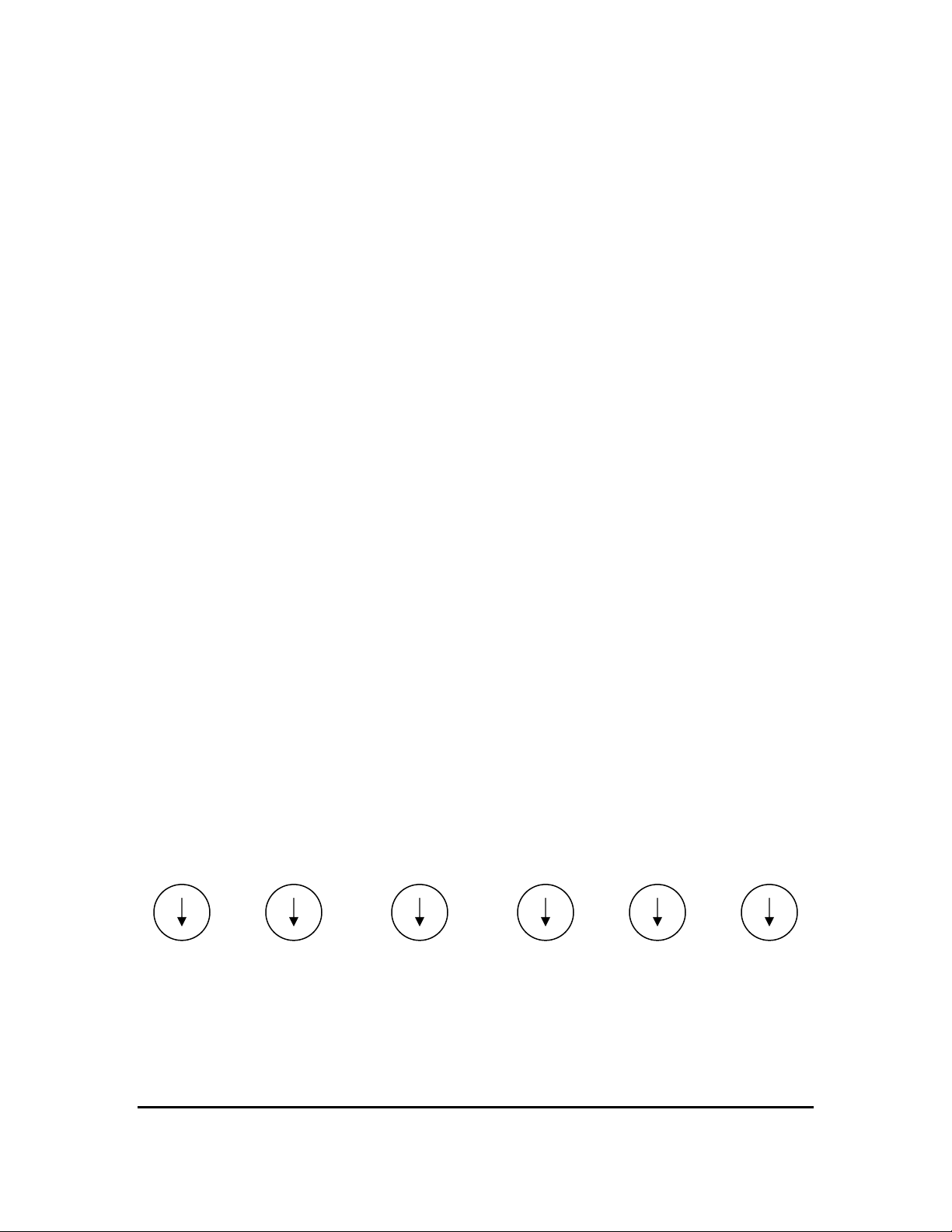
Step 1. Open the resistor packages and verify each resistor by the color code. Tape
or glue the template below to a piece of styrofoam or cardboard and punch a small hole in
the middle of each circle. The resistors may then be separated by value by sticking one
lead in the hole. The count of resistors per value per attenuator is below the values. The
colors of the 3 color code bands is below the count.
For reference: The color code for the value of these resistors is contained in the 3 colored
bands near one end. The gold band on the other end indicates the resistor tolerance of 5%.
The first 2 bands are coded as: 0=Black, 1=Brown, 2=Red, 3=Orange, 4=Yellow, 5=Green,
6=Blue, 7=Violet, 8=Gray, 9=White. The third band is the multiplier and, for resistors less than
10 Ohms, is either Silver (multiply by 0.01) or Gold (multiply by 0.1). An example: The three
bands are Red-Yellow-Gold which would be 2(Red) 4(Yellow) multiplied by 0.1(Gold) , 24 times
0.1 = 2.4 Ohms.
0.5 Ohms 1.0 Ohms 1.5 Ohms 2.4 Ohms 3.0 Ohms 3.6 Ohms
2 4 11 1 1 1
Green Brown Brown Red Orange Orange
Black Black Green Yellow Black Blue
Gold Silver Silver Silver Silver Silver
Resistor Separator Template (Use to Group Resistors by Values)
JVB ELECTRONICS SA-16-AR ASSEMBLY AND INSTALLATION GUIDE 2
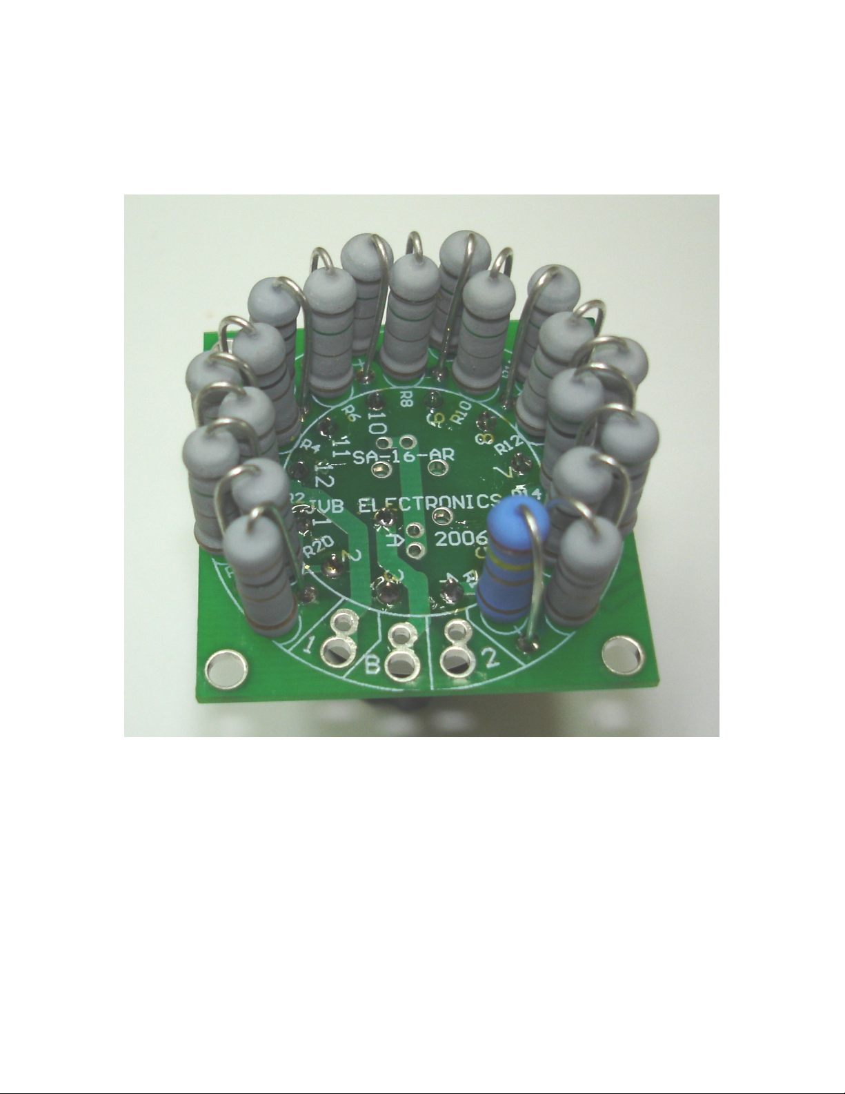
Notes on Installing Resistors. Each resistor will be installed “standing up” (See Figure
1.) Prepare the resistor for installation by gently bending one lead 180 degrees so that
both leads are parallel and close together
Figure 1. Completed SA-16-AR
.
Resistors will be installed on the silkscreened side of the printed circuit (the side with
white printing on it). The circle printed on the board surrounds the hole in the board that
the body side of the resistor will be mounted in. The short white line from the circle to
another hole indicates where the other lead (the bent-over) lead will mount. The
identifier (R1, R2, etc.) is printed near the circle in each case.
When mounting the resistor, allow about 1/8 inch of clearance between the body and the
board. This makes inspecting the solder joint easier and looks neat.
JVB ELECTRONICS SA-16-AR ASSEMBLY AND INSTALLATION GUIDE 3
 Loading...