

Page 1
HT60.book Page i Monday, April 2, 2007 6:28 PM
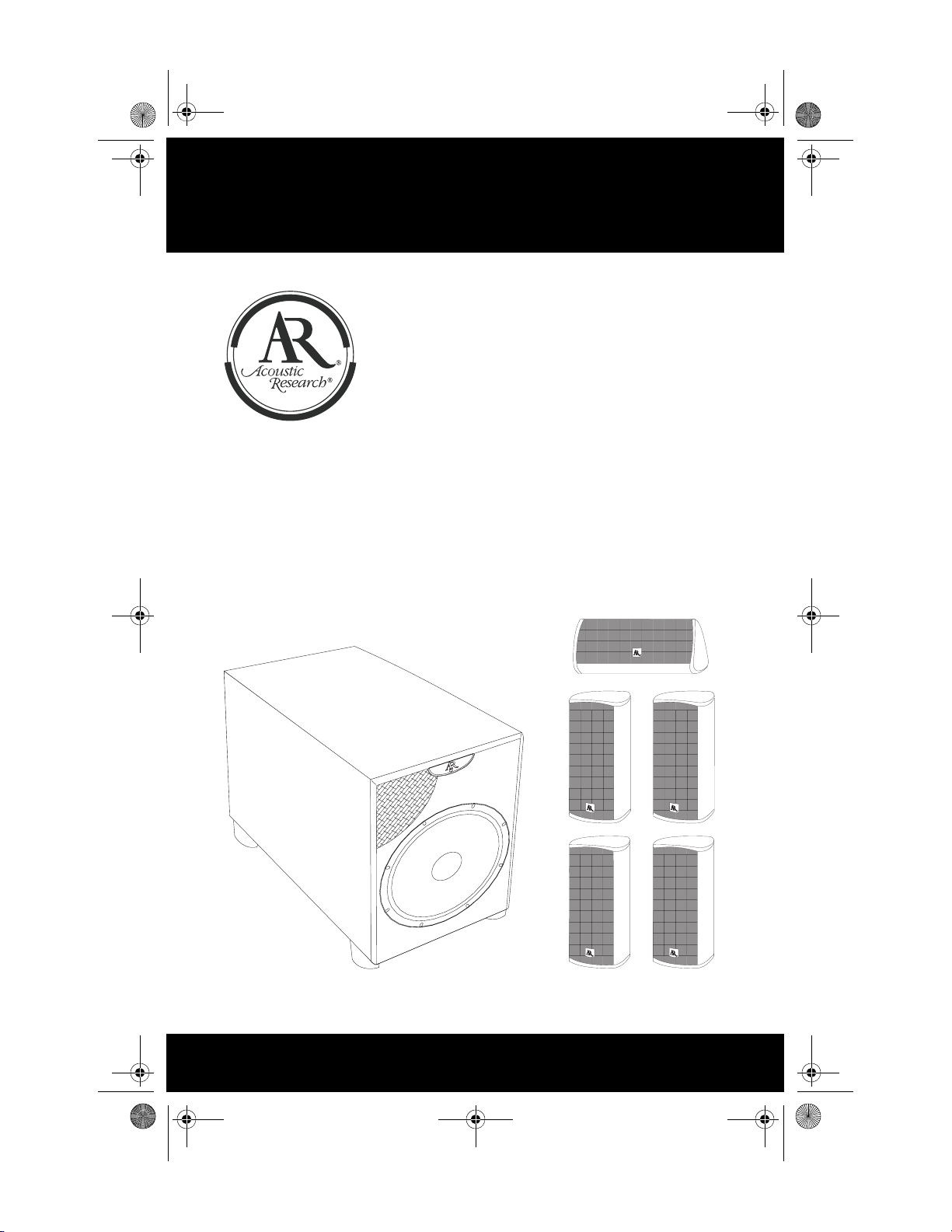
HT60
Installation and Operation Manual
Manual de la instalación y de la operación
Manuel d'installation et d'opération
Page 2

HT60.book Page i Monday, April 2, 2007 6:28 PM
HT60
Contents
Important Safety Instructions ........................................................................ 1
Introduction................................................................................................... 3
Surround System Configuration.................................................................... 5
Connecting the Subwoofer............ ... ... .... ... ................................................... 6
Subwoofer/Preamp Controls & Connections ................................................ 7
Installing your Surround Speakers................................................................ 9
Specifications.............................................................................................. 10
Home Audio 5 Year Limited Warranty ........................................................ 11
Contenido
Instrucciones de Seguridad Importantes .................................................... 13
Introducción ................................................................................................ 15
Configuración del Sistema Surround .......................................................... 17
Conectando el Altavoz de Graves o Subwoofer ......................................... 18
Controles y Conexiones de Altavoz de Graves/Preamplificador ................ 20
Instalando sus Altavoces Surround ........................ ...... .... ... ... ... ... .... ... ... ... . 22
Especificaciones ......................................................................................... 23
Garantía Limitada de 5 Años de Home Audio .............. .... ... ....................... 24
Table des matières
Instructions de Securite Importantes .......................................................... 25
Introduction................................................................................................. 27
Configuration du systeme quadriphonique ................................................. 29
Branchez le caisson de basse................................................... ... .... ... ... ... . 30
Caisson de basse/Connexions et Contrôles pré-amplificateur ................... 32
Installez vos hauts parleurs quadriphoniques............................................. 34
Spécifications.............................................................................................. 35
Audio à la maison Garantie limitée de 5 ans .............................................. 36
page i
Page 3

HT60.book Page ii Monday, April 2, 2007 6:28 PM
page ii
Page 4

Important Safety Instructions
1. Read these instructions.
2. Keep these instructions.
3. Heed all warnings.
4. Follow all instructions.
5. Do not use this apparatus near water.
6. Clean only with dry cloth.
7. Do not block any ventilation openings. Install in accordance with the manufacturer’s
instructions.
8. Do not install near any heat sources such as radiators, heat registers, stoves, or other
apparatus (including amplifiers) that produce heat.
9. Do not defeat the safety purpose of the polarized or grounding-type plug. A polarized
plug has two blades with one wider than the other. A grounding type plug has two blades
and a third grounding prong. The wide blade or the third prong are provided for your
safety. If the provided plug does not fit into your outlet, consult an electrician for
replacement of the obsolete outlet.
10. Protect the power cord from being walked on or pinched particularly at plugs,
convenience receptacles, and the point where they exit from the apparatus.
11. Only use attachments/accessories specified by the manufacturer.
12. Use only with the cart, stand, tripod, bracket, or table specified by the
manufacturer, or sold with the apparatus. When a cart is used, use caution when
moving the cart/apparatus combination to avoid injury from tip-over.
13. Unplug this apparatus during lightning storms or when unused for long periods of
time.
14. Refer all servicing to qualified service personnel. Servicing is required when the
apparatus has been damaged in any way, such as power-supply cord or plug is damaged,
liquid has been spilled or objects have fallen into the apparatus, the apparatus has been
exposed to rain or moisture, does not operate normally, or has been dropped.
15. WARNING: To reduce the risk of fire or electric shock, do not expose this apparatus to
rain or moisture.
16. Where the mains plug or an appliance coupler is used as the disconnect device, the
disconnect device shall remain readily operable.
17. CAUTION: These servicing instructions are for use by qualified service personnel only. To
reduce the risk of electric shock do not perform any servicing other than that contained in
the operating instructions unless you are qualified to do so.
18. Do not install this equipment in a confined space such a book case or similar unit.
19. Maintain minimum 10 cm free space around the apparatus for sufficient ventilation.
Page 5

20. The ventilation should not be impeded by covering the ventilation openings with items,
such as newspapers, ta ble -clot hs , c urtai ns , etc .
21. No naked flame sources, such as lighted candles, should be placed on the apparatus.
22. The apparatus should be used in moderate clim ate.
23. The apparatus shall not be exposed to dripping or splashing and that no objects filled with
liquids, such as vases, shall be placed on the apparatus.
Page 6
HT60.book Page 2 Monday, April 2, 2007 6:28 PM
The lightning flash with arrowhead symbol within an equilateral triangle is intended to alert the user to the presence of “dangerous voltage” within the product’s enclosure that may be of significant
magnitude to constitute a risk of electrical shock to persons.
The exclamation point within an equilateral triangle is intended to
alert the user to the presence of important operating and maintenance
(servicing) instructions in the literature accompanying this product.
page 2
Page 7

HT60.book Page 3 Monday, April 2, 2007 6:28 PM
HT60
Introduction
NOTE: Check your system immediately. If it has been damaged in transit, report the damage immediately by calling your AR dealer.
Please follow the directions in this manual to achieve the best performance from your
system.
The hook-up and operation of the subwoofer is the same for a home theater surround
system and a stereo music system. The subwoofer has a built-in amplifier, making it
compatible with any sound system. In addition, the subwoofer's crossover networks
send bass-only signals to its built-in amplifier, allowing the subwoofer to add extra
bass to the output from your other speakers.
To simplify the instructions in this manual, the main speakers are referred to as the
“front speakers”. The AV receiver, stereo receiver, or integrated amplifier is referred
to as the “receiver.”
Warnings
We recommend that you not operate your speakers with the bass, treble, and loudness
controls set to full boost. This will place undue strain on the electronics and speakers
and could damage them.
The volume control setting on your receiver is not a specific indication of the overall
loudness level of the speakers. The only important consideration is the loudness level
at which the system can be played, regardless of where the volume control is set.
Whenever changing cables or pulling plugs, ALWAYS TURN OFF ALL EQUIPMENT. This prevents transients from entering the speakers and prevents electrical energy from reaching you.
Keep all connections out of the reach of children.
page 3
Page 8
HT60.book Page 4 Monday, April 2, 2007 6:28 PM
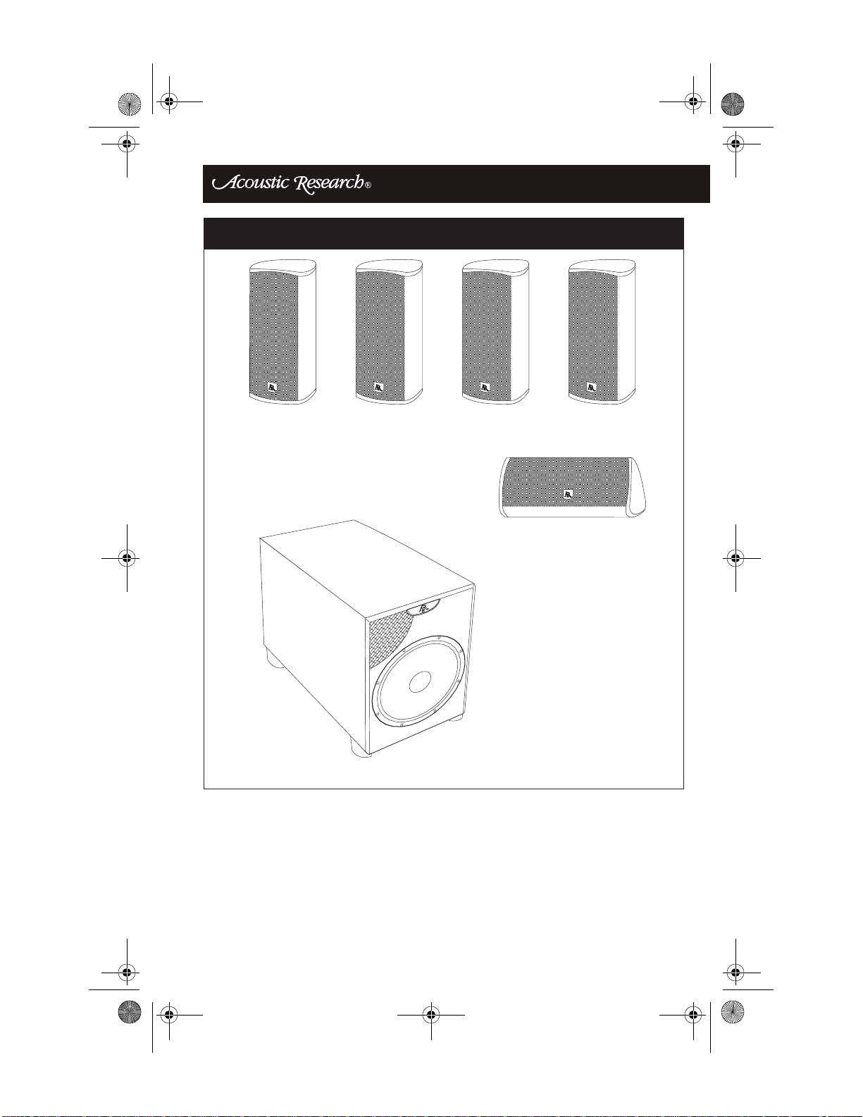
FIGURE 1 - Parts Reference
SURROUND SPEAKERS (x 4)
CENTER CHANNEL SPEAKER (x 1)
SUBWOOFER (x1)
page 4
Page 9
HT60.book Page 5 Monday, April 2, 2007 6:28 PM
HT60
Surround System Configuration
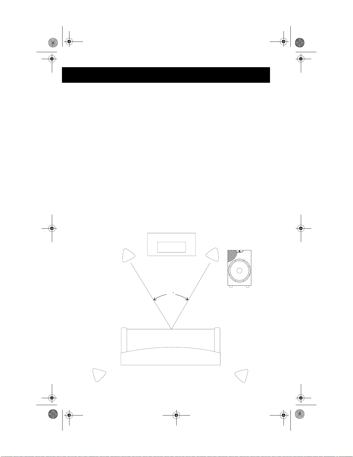
The optimum listening position is at the tip of the “stereo triangle.” The equilibrium
between the right and left stereo channels is best in this position, providing the most
balanced and realistic sound reproduction. Your AR speakers will operate most efficiently when located in parts of the room with “hard” acoustics, i.e., areas including
hard, smooth surfaces such as walls and wooden furniture. The speakers should radiate
the sound from this hard area into the “softer” parts of the room containing sound-absorbing elements such as upholstered furniture, carpets and so on. Try to avoid placing
sound-absorbing obstacles between the speakers and your listening position, as this
will muffle the sound and impair your listening pleasure. Your HT60 Series speakers
are fully shielded for use in audio/video applications. This allows you to place any of
the speakers next to the television without affecting picture quality. If you are using
other speakers, be sure to locate them at least 3 feet from the television to avoid interference to the set’s picture. Installing the speakers at least 1 foot away from the side
walls will prevent exaggerated “booming” bass and produce more balanced, detailed
sound reproduction. If possible, the speakers should be installed with the tweeters on
the same level as the listener's ears. If you install the speakers in a wall unit, make sure
the fronts of the speakers are flush with the front of the wall unit. Rear speakers should
be placed approx at ear level or slightly higher. The center channel speaker should be
placed above or below the television.
LEFT REAR
FIGURE 2 - System Configuration
CENTER FRONT
LEFT FRONT
45
LISTENING AREA
RIGHT FRONT
SUBWOOFER
RIGHT REAR
page 5
Page 10
HT60.book Page 6 Monday, April 2, 2007 6:28 PM
Connecting the Subwoofer
IMPORTANT: To avoid damaging your equipment, make sure the subwoofer
and all components are turned off before making any connections.
Subwoofer Placement
Placement of your subwoofer will dramatically affect its performance. Your AR subwoofer is designed to work best when placed on the floor within 15 feet of your front
speakers. For detailed accurate bass response, place your subwoofer near a wall, but
away from a corner. If you prefer fuller, more accentuated bass, try placing your subwoofer directly in a corner. This will substantially increase bass response. When possible, place the subwoofer close to your system's front speakers to keep wire or cable
runs short. See “Surround System Configuration” on page 5 for more information on
speaker placement.
Since low frequency sound is omni-directional, the subwoofer can be placed anywhere
in the room. Use the Low Pass Frequency control and the Phase switch to adjust the
output. Use the subwoofer's Level control to adjust the volume relative to the placement (this may require resetting the subwoofer's polarity switch). See “Subwoofer/
Preamp Controls & Connections” on page 7 for details on adjusting these settings.
Connecting the Subwoofer Line-In
Connect an audio cable from the Subwoofer output on your receiver to the Line-In inputs on the subwoofer. Note that the subwoofer has a left and right input, allowing it
to receive stereo bass signals. If your receiver has only one output, you can run a single
audio cable into either the left or right input on the subwoofer. Another option is to use
a “Y” cable to connect both the left and right inputs on the subwoofer.
Connecting the Speaker Level (High Level) Inputs
For older receivers with no LFE or Subwoofer outputs, run speaker wire from your receiver's front left and right speaker level outputs to the left and right speaker level inputs on the subwoofer. Connect the front left and right surround speakers in parallel
with the subwoofer.
NOTE: To avoid possible output problems, do NOT use the "speakers B" output to attach the subwoofer to a receiver.
IMPORTANT: All speakers in a system must be connected with the same polarity. Polarity is indicated by a color stripe on the insulation, by ridges molded into the insulation, or by the colors of the wire - one copper and one silver.
Strip the insulation from the speaker wire ends to reveal the bare conductors
before connecting to a speaker, subwoofer or receiver. Always connect the red
(+) terminal on the receiver to the red (+) terminal on the Subwoofer, and connect the black (-) terminal on the receiver to the black (-) terminal on the Subwoofer. The same is true for hooking up the Receiver outputs to the Front
speakers: red (+) to red and black (-) to black.
page 6
Page 11
HT60.book Page 7 Monday, April 2, 2007 6:28 PM
HT60
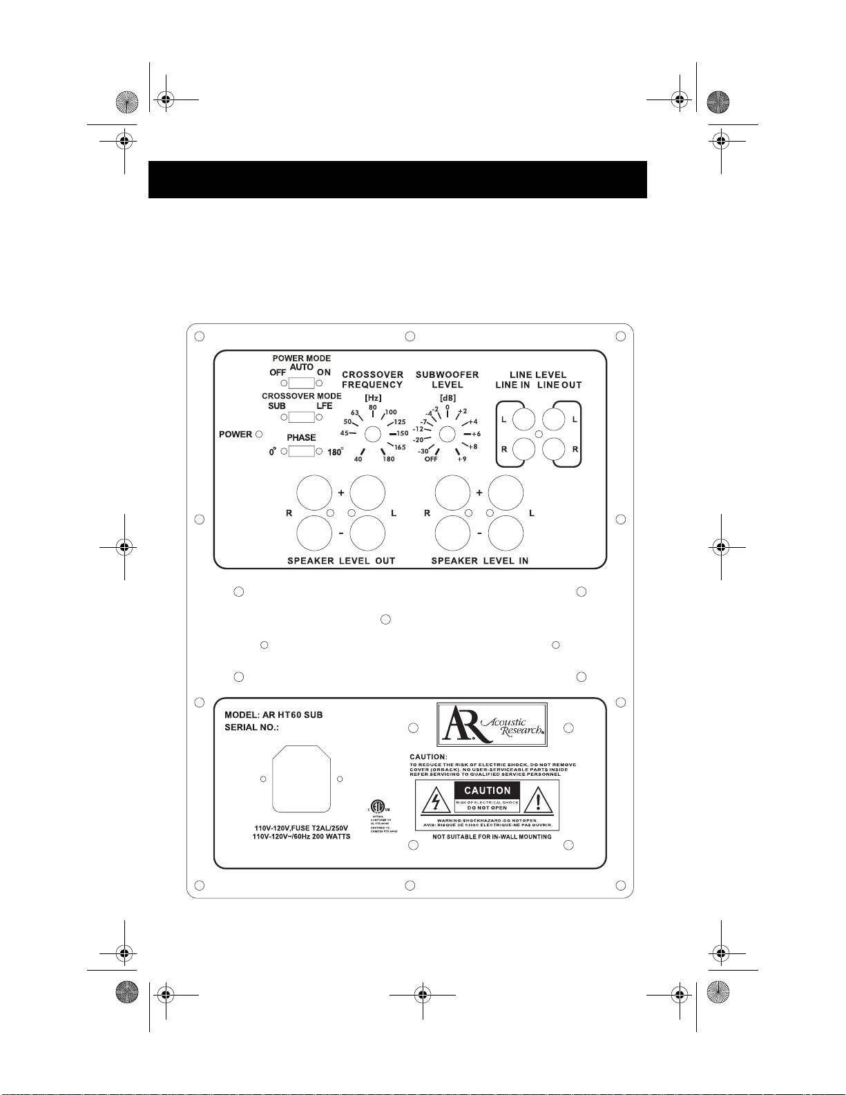
Subwoofer/Preamp Controls & Connections
The amplifier and subwoofer controls are located on the back of the subwoofer cabinet,
shown in Figure 3.
FIGURE 3 - Subwoofer/Preamp Controls & Connections
page 7
Page 12

HT60.book Page 8 Monday, April 2, 2007 6:28 PM
• Power cord: Plug the power cord into an AC wall outlet.
• MODE (AUTO ON/OFF): Move this switch to turn the AC supply OFF/
ON. When AUTO ON is selected, the Subwoofer remains in the stand-by
mode until an audio signal is detected. (During standby mode, the front
LED indicator remains un-lit, while the rear indicator is illuminated red.)
After a few minutes without an audio signal, the Subwoofer automatically
reverts to stand-by mode.
• SUB/LFE: Move this switch to select LFE or SUB (normal subwoofer)
mode. Select LFE mode if you are using your receiver’s LFE output.
• POWER: The green LED POWER indicator on the front illuminates blue
and the LED indicator on the back illuminates green when the amplifier is
turned on.
• Fuse: The 250v 2.0A (AGC Type) is located on the amplifier panel on the
back of the Subwoofer cabinet under the power cord. This fuse protects
against internal and external faults. If the Power switch is ON but the
power indicator LED remains unlit, the fuse should be replaced. T o replace
the fuse, unplug the power cord from the AC outlet, then unscrew the
center piece and replace the fuse.
IMPORTANT: If the fuse is blown, replace it ONLY with a fuse of the
same type and current rating (250v 2.0A). Severe damage or fire could
result from improper fuse replacement.
• SPEAKER LEVEL IN/OUT (L and R): These terminals are used for making connections with speaker wire.
• LINE LEVEL IN/OUT (L and R): These connections are used for bass
audio signals.
• CROSSOVER FREQUENCY: Adjust the system’s tonal balance by setting the upper frequency limit (40Hz-180Hz) for the audio signals going to
the subwoofer.
• SUBWOOFER LEVEL: Bal ance the loudness (OFF, or -30dB to +9dB) of
the subwoofer relative to the front speakers and compensate for room
effects on the subwoofer .
• PHASE: Contro l th e ph ase o f th e subwoofer relative to the front speakers.
To determine the appropriate phase setting, select either regular (0°) or
inverted (180°) and perform a sound test. Listen carefully to the sound
quality while playing a CD with low bass such as percussion or bass lines,
then select the position that produces the fullest and most dynamic bass.
You may need to adjust the LEVEL control (volume) and the CROSSOVER FREQUENCY control after setting the PHASE switch.
page 8
Page 13

HT60.book Page 9 Monday, April 2, 2007 6:28 PM
HT60
Installing your Surround Speakers
The surround speakers are identical and can be used for any channel.
Surround Speaker Placement
Speaker placement is critical, and can make the difference between good and great
sound quality. For optimum sound quality, position your front (main) surround speakers slightly in front of the video screen and turn them slightly inward (towards the center of the listening area). This reduces the possibility of reflection from the video
screen or side walls. Turning the surround speakers farther inward produces a smaller
sound stage and focuses the sound more directly to the listener's ear. Turning them less
or not at all produces a larger sound stage and compromises localization of the sounds.
Placing the left and right surround speakers closer to the front wall, side walls, or corners will increase the amount of audible bass. The HT60 surround speakers are designed to be placed within 18 inches of a wall for optimum tonal balance. Rear
speakers should be placed approx at ear level or slightly higher. The center channel
speaker should be placed above or below the television. Based on your listening preferences, you will want to experiment with the placement of your surround speakers.
When possible, the surround speakers should be installed at the same level as the listener's ears. See “Surround System Configuration” on page 5 for more information on
speaker placement.
Connecting the Surround Speakers
Strip approximately 3/8" of the insulation from the speaker wire, exposing the bare
conductors. Twist each end of the speaker wire, and then connect the speakers in phase.
Connect the positive (+) terminal from the Receiver to the positive (+) terminal on the
speaker. Red typically indicates positive. Connect the negative (-) terminal from the
Receiver to the negative (-) terminal on the speaker. Black is typically the color code
for negative.
Wall Mounting
Your HT60 surround speakers can be mounted to the wall using the ¼-20 threaded insert located on the back of the speaker. This is designed for use with after-market
mounting hardware. See your local dealer for details.
page 9
Page 14

HT60.book Page 10 Monday, April 2, 2007 6:28 PM
Specifications
Surround Speakers:
Driver Complement: 2 Way Satellite
Woofer (2) 3" Treated Cellulose (Magnetically Shielded)
Tweeter 1/2” PEI dome (Magnetically Shielded)
Frequency Response: 100Hz – 20,000Hz (+/–3db)
Recommended Amplifier Power: 15 – 100 watts
Sensitivity: 91dB
Nominal Impedance: 8 ohms
Finish: Extruded Aluminum
Dimensions: 8"H x 3 1/2"W x 3 3/8"D
Weight: 2.7 lb (1.2kg)
Subwoofer:
Driver Complement: 10" Non-Pressed Paper Cone
Frequency Response: 25Hz – 180Hz (+/-3dB)
Crossover Frequency: 40Hz - 180Hz, 24dB/octave continuously variable
Amplification Power Output: 125 watts RMS into 4 Ohms
Total Harmonic Distortion: 10% @ 125 Watts output
Finish: Black Ash Vinyl
Dimensions: 16"H x 10.5"W x 15.5"D
Weight: 36 lb
page 10
Page 15

HT60.book Page 11 Monday, April 2, 2007 6:28 PM
HT60
Home Audio 5 Year Limited Warranty
Audiovox Electronics Corp; (the Company) warrants to the original retail purchaser of
this product that has been purchased from an authorized AR dealer, that should this
product or any part thereof (except as herein provided), under normal use and conditions, be proven defective in material or workmanship within 5 years from the original
date of purchase, such defects will be replaced or repaired (at the Company’s option)
without charge for parts and repair labor.
Speakers with built in amplifiers are similarly warranted for 12 months.
To obtain repair or replacement within the terms of this warranty the product is to be
delivered with proof of warranty coverage (e.g. dated bill of sale), specification of defect (s), transportation prepaid, to the Company at the address shown below.
THE FOLLOWING ARE NOT COVERED: Costs incurred for installation, removal or reinstallation of the product; Damage to accessories, or electrical systems; Damage caused by accident, misuse, abuse, product modification or neglect; Damage
occurring during shipment; Damage resulting from improper repairs. This warranty
does not cover incidental or consequential damages. This warranty is void if the serial
number is removed. THE EXTENT OF THE COMPANY’S LIABILITY UNDER
THIS WARRANTY IS LIMITED TO THE REPAIR OR REPLACEMENT PROVIDED ABOVE AND, IN NO EVENT, SHALL THE COMPANY’S LIABILITY
EXCEED THE PURCHASE PRICE PAID BY THE PURCHASER FOR THE
PRODUCT.
This Warranty is in lieu of all other express warranties or liabilities. ANY IMPLIED
WARRANTIES, INCLUDING ANY IMPLIED WARRANTY OF MERCHANTABILITY, SHALL BE LIMITED TO THE DURATION OF THIS WRITTEN WARRANTY. ANY ACTION FOR BREACH OF ANY WARRANTY HEREUNDER
INCLUDING ANY IMPLIED WARRANTY OF MERCHANTABILITY MUST BE
BROUGHT WITHIN A PERIOD OF 72 MONTHS FROM DATE OF ORIGINAL
PURCHASE. IN NO CASE SHALL THE COMPANY BE LIABLE FOR ANY CONSEQUENTIAL OR INCIDENTL DAMAGES FOR BREACH OF THIS OR ANY
OTHER WARRANTY, EXPRESS OR IMPLIED, WHATSOEVER. No person or
representative is authorized to assume for the Company any liability other than expressed herein in connection with the sale of this product.
Some states do not allow limitations on how long an implied warranty lasts or the exclusion of limitation of incidental or consequential damage so the above limitations or
exclusions may not apply to you. This Warranty gives you specific legal rights and you
may also have other rights which vary from state to state.
How to Obtain Service
Please contact us at 800-225-9847 or write to:
Acoustic Research (Attention: Customer Service Department), AB Tech Services, 17C
Airport Drive, Hopedale, MA 01747
page 11
Page 16

HT60.book Page 12 Monday, April 2, 2007 6:28 PM
page 12
Page 17
HT60.book Page 13 Monday, April 2, 2007 6:28 PM
HT60
Instrucciones de Seguridad Importantes
• Lea estas instrucciones.
• Mantenga éstas instrucciones en un lugar seguro.
• Preste atención a todas las instrucciones.
• Siga todas las instrucciones.
• No utilice este aparato cerca del agua.
• Limpie sólo con paño seco.
• No obstruya ninguna apertura de ventilación. Realice la instalación de
acuerdo a las instrucciones del fabricante.
• No realice la instalación cerca de ninguna fuente de calor incluyendo un
radiador, un circuito de calor, estufa u otro aparato (incluyendo un amplificador) que produzca calor.
• No anule el propósito de seguridad del enchufe de tipo polarizado o con
toma a tierra. Un enchufe polarizado tiene dos patas, una más ancha que la
otra. Un enchufe con toma a tierra tiene dos patas y una tercera púa con
toma a tierra. La pata ancha y la tercera púa se proveen por razones de seguridad. Si el enchufe no entra en su toma, consulte a un electricista para
reemplazar la toma existente.
• Proteja el cable de alimentación de pisotones o pinchaduras, particularmente cerca del enchufe, en los receptáculos y en el punto de salida del
aparato.
• Sólo utilice los accesorios o complement os especificados po r el fabricante.
• Desenchufe este aparato durante tormentas eléctricas o cuando vaya a estar
en desuso por largos períodos de tiempo.
• Realice todos los servicios con personal calificado. El servicio es necesario
cuando el aparato se ha dañado de alguna forma, tal como cuando se daña
el cable o el enchufe, se derrama líquido encima o se le han caído objetos
arriba del aparato, o cuando éste ha estado expuesto a lluvia o humedad, no
opera normalmente o se ha caído.
page 13
Page 18

HT60.book Page 14 Monday, April 2, 2007 6:28 PM
La luz centellante con el símbolo de cabeza de flecha, dentro de un
triángulo equilátero, intenta alertar al usuario de la presencia de un
"voltaje peligroso" dentro del producto de tal magnitud que signifique un riesgo de choque eléctrico a las personas.
El signo de exclamación dentro de un triángulo equilátero en los
manuales que acompañan este producto indican al usuario que esas
son instrucciones de mantenimiento (servicio) importantes.
page 14
Page 19

HT60.book Page 15 Monday, April 2, 2007 6:28 PM
HT60
Introducción
NOTA: Verifique inmediatamente su sistema. Si ha sido dañado en tránsito, reporte el daño inmediatamente llamando a su distribuidor AR.
Por favor siga las instrucciones de este manual para lograr el mejor desempeño de su
sistema.
La conexión y operación del altavoz de graves, llamado "subwoofer" en inglés, es el
mismo para un sistema surround de home theater como para un sistema de música estéreo. El altavoz de graves tiene un amplificador integrado que lo hace compatible con
cualquier sistema de sonido. Además, las redes de cruzamiento del altavoz de graves
envían sólo señales graves al amplificador integrado, permitiendo al altavoz de graves
agregar sonidos bajos extras a la salida de los otros altavoces.
Para simplificar las instrucciones en este manual, los altavoces principales son llamados "altavoces delanteros". El sintonizador AV, receptor estéreo o amplificador integrado son llamados el "receptor".
Advertencias
Le recomendamos no operar sus altavoces con los controles de graves, agudos y sonoridad en su capacidad máxima. Esto colocará tensión excesiva en la electrónica y los
altavoces que podría dañarlos.
La posición del volumen en el receptor no lleva una indicación específica en cuanto al
nivel de sonoridad general de sus altavoces. La única consideración importante es el
nivel de sonoridad en el cual el sistema se puede usar, sin importar en dónde se posicione el volumen.
Cuando cambie cables o jale enchufes, SIEMPRE APAGE TODO EL EQUIPO. Esto
previene que oscilaciones momentáneas en los altavoces y previene que lo alcance energía eléctrica.
Mantenga todas las conexiones fuera del alcance de los niños.
page 15
Page 20

HT60.book Page 16 Monday, April 2, 2007 6:28 PM
FIGURA 1 - Referencia de las Piezas
ALTAVOCES SURROUND (x 4)
ALTAVOZ DE CENTRO (x 1)
SUBWOOFER (x 1)
page 16
Page 21

HT60.book Page 17 Monday, April 2, 2007 6:28 PM
HT60
Configuración del Sistema Surround
La posición de escucha óptima es en la punta de un "triángulo estéreo". El equilibrio
entre canales estéreos derecho e izquierda es mejor en esta posición, brindando la reproducción de sonido más balanceada y realista. Sus altavoces AR no operarán más
eficientemente cuando estén ubicados en lugares de la habitación con acústica "dura",
por ejemplo en áreas con superficies duras y lisas como paredes y muebles de madera.
Los altavoces deben irradiar el sonido desde esta área dura hacia partes "blandas" de
la habitación que contengan elementos absorbentes del sonido tal como muebles
tapizados, alfombras y elementos similares. Evite colocar obstáculos absorbentes del
sonido entre los altavoces y su posición de escucha, pues esto amortigua el sonido e
impide un sonido placentero. Sus altavoces de la Serie HT60 están completamente
protegidos y preprados para ser usados con dispositivos de audio y video. Esto le permite colocar cualquier altavoz cerca del televisor sin afectar la calidad de la imagen.
Si usted está utilizando otros altavoces, asegúrese de ubicarlo al menos a 3 pies de su
televisor para evitar la interferencia en la imagen del equipo. Instalar los altavoces al
menos a 1 pie de las paredes evita "estruendos" exagerados de graves y produce sonidos más balanceados y detallados. Si es posible, los altavoces deberían estar instalados
con altavoces de agudos, llamados "tweeters" en inglés, en el mismo nivel de los oídos
de quien escucha. Si instala los altavoces en un módulo de pared, asegúrese que los
frentes de los altavoces estén alineados con el frente del módulo. Los altavoces traseros deben ser colocados aproximadamente a niveles del oído o un poco más arriba. El
altavoz del canal central debe ser colocado sobre o debajo del televisor.
FRONTAL IZQUIERDO
POSTERIOR
IZQUIERDO
FIGURA 2 - Configuración de Sistema
CENTRO FRONTAL
FRONTAL DERECHO
45
CAMPO AUDITIVO
page 17
ALTA VOZ DE
SUBGRAVES
POSTERIOR
DERECHO
Page 22

HT60.book Page 18 Monday, April 2, 2007 6:28 PM
Conectando el Altavoz de Graves o Subwoofer
IMPORTANTE: Para evitar dañar su equipo, asegúrese que el altavoz de
graves y todos los componentes estén apagados antes de realizar alguna conexión.
Ubicación del Altavoz de Graves
La ubicación del altavoz de graves afectará dramáticamente su desempeño. Su altavoz
de graves AR está diseñado para funcionar mejor cuando se coloca en el suelo a menos
de 15 pies de los altavoces delanteros. Para obtener sonidos graves precisos y detallados, coloque su altavoz de graves cerca de una pared pero lejos de una esquina. Si prefiere graves más llenos y acentuados, intente ubicar su altavoz directamente en una
esquina. Esto aumentará la respuesta de graves sustancialmente. Cuando sea posible,
ubique el altavoz cerca de los altavoces delanteros para mantener los cables cortos.
Lea “Configuración del Sistema Surround” en la página 17 para obtener más información sobre ubicación de altavoces.
Debido a que el sonido de frecuencia baja es omnidireccional, el altavoz de graves se
puede ubicar en cualquier lugar de la habitación. Utilice el control de Frecuencia de
Paso Bajo y la llave de Fase para ajustar la salida. Utilice el control de Nivel del altavoz
de graves para ajustar el volumen en relación al lugar (esto puede requerir restablecer
la llave de polaridad del altavoz de graves). Lea “Conectando el Altavoz de Graves o
Subwoofer” en la página 18 para obtener detalles sobre el ajuste de estas configuraciones.
Conectando la Línea de Entrada del Altavoz de Graves
Conecte un cable de audio desde la salida para Altavoz de Graves en su receptor a la
entrada en el altavoz de graves. Note que el altavoz de graves tiene entradas izquierda
y derecha, permitiéndole recibir señales estéreo de graves. Si su receptor tiene solamente una salida, usted puede colocar un solo cable de audio ya sea en la entrada izquierda o en la derecha del altavoz de graves. Otra opción es usar un cable "Y" para
conectar ambas entradas, izquierda y derecha, del altavoz de graves.
Conectando las Entradas de Nivel (Alto Nivel) del Altavoz
Para receptores viejos sin LFE (efectos de baja frecuencia) o salidas de Altavoces de
Graves, coloque cable de altavoz desde la salida de altavoz derecha o izquierda
delantera de su receptor a las entradas de altavoces derecho o izquierdo en su altavoz
de graves. Conecte los altavoces envolventes, llamados "surround" en inglés,
delanteros derecho e izquierdo en paralelo con el altavoz de graves.
NOTA: Para evitar posibles problemas de salida, NO use la salida de los "altavoces B" para conectar el altavoz de graves a un receptor.
IMPORTANTE: Todos los altavoces en un sistema deben estar conectados con
la misma polaridad. La polaridad se indica con una tira de colo r en el aislamiento, con bordes moldeados en el aislamiento o por los colores de los cables - uno cobre y uno plateado. Quite el aislamiento del extremo de los cables
page 18
Page 23

HT60.book Page 19 Monday, April 2, 2007 6:28 PM
HT60
de altavoz hasta dejar los conductores pelados antes de conectar a un altavoz,
altavoz de graves o receptor. Siempre conecte el terminal rojo (+) en el receptor, al terminal rojo (+) en el Altavoz de Graves, y conecte el terminal negro
(-) en el receptor, al terminal negro (-) en el Altavoz de Graves. Lo mismo rige
para la conexión de las salidas del Receptor a los Altavoces Delanteros: rojo
(+) a rojo y negro (-) a negro.
page 19
Page 24

HT60.book Page 20 Monday, April 2, 2007 6:28 PM
Controles y Conexiones de Altavoz de
Graves/Preamplificador
The amplifier and subwoofer controls are located on the back of the subwoofer cabinet,
shown in Figure 3.
FIGURA 3 - Controles y Conexiones de Altavoz de Graves/Preamplificador
page 20
Page 25

HT60.book Page 21 Monday, April 2, 2007 6:28 PM
HT60
• Cable de energía: Enc hufe el cable de energía a una toma de corriente
alterna en la pared.
• MODE (AUT O ON/OFF): Mueva esta llave para apagar o encender (OFF/
ON) la alimentación de corriente alterna. Cuando se selecciona AUTO
ON, el Altavoz de Grave permanece en modo stand-by, sin hacer nada
hasta que se detecte una señal de audio. (Durante el modo stand-by, el indicador LED delantero permanece sin iluminar, mientras que el indicador
trasero se ilumina en rojo.) Luego de algunos minutos sin una señal de
audio, el Altavoz de Graves automáticamente vuelve a modo stand-by.
• SUB/LFE: Mueva esta llave para seleccionar modos LFE o SUB (altavoz
grave normal). Seleccione modo LFE si usted está usando la salida de
efectos de baja frecuencia de su receptor.
• POWER: El indicador LED verde de encendido en el frente se ilumina
azul y el indicador LED en la parte trasera ilumina verde cuando se
enciende el amplificador.
• Fusible: El fusible 250v 2.0A (Tipo AGC) se coloca en el panel del amplificador en la parte trasera del gabinete del Altavoz de Graves bajo el cable
de energía. Este fusible protege contra fallas internas y externas. Si la
llave de encendido (Power) está en ON (Encendida) pero el indicador LED
permanece apagado, el fusible debe ser reemlazado. Para reemplazar el
fusible, desenchufe el cable de energía de corriente alterna, luego destornille la pieza central y reemplace el fusible.
IMPORTANTE: Si se quema el fusible, reemplácelo SOLAMENTE
con un fusible del mismo tipo e índice de corriente (250v 2.0A). El
recambio inadecuado de fusible puede causar daños severos o incendio.
• SPEAKER LEVEL IN/OUT (ENTRADA/SALIDA DE NIVEL DE
ALTAVOZ) (L por izquierdo y R por derecho): Estos terminales se usan
para realizar conexiones con cables de altavoces.
• LINE LEVEL IN/OUT (ENTRADA/SALIDA DE NIVEL DE LÍNEA) (L
por izquierdo y R por derecho): Estas conexiones se usan para señales de
audio graves.
• CROSSOVER FREQUENCY (FECUENCIA DE CRUZAMIENTO):
Ajuste el balance tonal del sistema configurando el límite de frecuencia
superior (40Hz-180Hz) para señales de audio que vayan al altavoz de
graves.
• SUBWOOFER LEVEL (NIVEL DE ALTAVOZ DE GRAVES): Realice el
balance de sonoridad (OFF, ó -30dB a +9dB) del altavoz de graves en relación a los altavoces delanteros, y compense los efectos de la habitación en
el altavoz de graves.
• PHASE (FASE): Controle la fase del altavoz de graves relativo a los altavoces delanteros. Para determinar la configuración de fase adecuada, seleccione ya sea regular (0°) o invertido (180°) y realice una prueba de sonido.
Escuche cuidadosamente la calidad de sonido mientras reproduzca un CD
con graves bajos tal como percusión o líneas de graves, luego seleccione la
posición que produzca los graves más llenos y dinámicos. Tal vez necesite
ajustar el control de NIVEL (volumen) y el control de FRECUENCIA DE
CRUZAMIENTO luego de configurar la llave de FASE.
page 21
Page 26

HT60.book Page 22 Monday, April 2, 2007 6:28 PM
Instalando sus Altavoces Surround
Los altavoces surround son idénticos y se pueden usar para cualquier canal.
Ubicación del Altavoz Surround
La ubicación del altavoz es crítica y puede marcar la diferencia entre una buena o una
excelente calidad de sonido. Para una calidad de sonido óptima, coloque sus altavoces
envolventes delanteros (principales) levemente al frente de la pantalla de video y gírelos un poco hacia adentro (hacia el centro del área de escucha). Esto reduce la posibilidad de reflejo de la pantalla de video o de las paredes. Girando los altavoces
envolventes un poco más hacia dentro produce una etapa de sonido más pequeña y enfoca el sonido más directamente al oído de quien escucha. Girarlos poco o nada produce una etapa de sonido más grande y compromete la localización de los sonidos.
Ubicar los altavoces envolventes izquierdo y derecho más cerca de la pared delantera,
laterales o esquinas incrementará la suma de graves audibles. Los altavoces envolventes HT60 están deseñados para ser colocados a menos de 18 pulgadas de una pared
para obtener un balance tonal óptimo. Los altavoces traseros deben ser colocados
aproximadamente a niveles del oído o un poco más alto. El altavoz del canal central
debe ser colocado sobre o debajo del televisor. Basado en sus preferencias de audio,
usted puede experimentar con la ubicación de sus altavoces envolventes. Cuando sea
posible, los altavoces envolventes deberían ser instalados al nivel de los oídos de quien
escucha. Lea “Configuración del Sistema Surround” en la página 17 para obtener más
información sobre la ubicación de los altavoces.
Conectando los Altavoces Envolventes
Quite aproximadamente 3/8" del aislamiento del cable de altavoz, exponiendo los conductores pelados. Gire cada extremo del cable de altavoz, y luego conecte los altavoces
en fase. Conecte el terminal positive (+) desde el Receptor a un terminal positivo (+)
en el altavoz. El rojo típicamente indica positivo. Conecte el terminal negativo(-) desde el Receptor a un terminal negativo (-) en el altavoz. El negro es típicamente el código de color para negativo.
Montaje en Pared
Sus altavoces surround HT60 se pueden montar en la pared usando la rosca ¼-20
ubicada en la parte trasera del altavoz. Esto está diseñado para utilizar herramientas de
montaje del mercado. Vea a su revendedor local por detalles.
page 22
Page 27

HT60.book Page 23 Monday, April 2, 2007 6:28 PM
HT60
Especificaciones
Altavoces Surround:
Complemento del Controlador: Satélite de 2 Vías
Altavoz de Graves (2) con 3" de Tratamiento con Celulosa (Protegido Magnética-
mente)
Altavoz de Agudo con cúpula PEI de 1/2" (Protegido Magnéticamente)
Frecuencia de Respuesta 100Hz - 20.000Hz (+/-3db)
Energía para el Amplificador Recomendada: 15 - 100 wats
Sensibilidad: 91dB
Impedancia Nominal: 8 ohms
Terminación: Aluminio Extruído
Dimensiones : 8"Alto x 3 1/2" Ancho x 3 3/8" Profundidad
Peso: 2.7 lb (1.2kg)
Altavoz de Graves o Subwoofer:
Complemento del Controlador: Cono de Papel No Prensado de 10"
Frecuencia de Respuesta 25Hz - 180Hz (+/-3db)
Fecuencia de Cruzamiento: 40Hz - 180Hz, 24dB/octava variable continuamente
Salida de Energía de la Amplifiación: 125 wats RMS en 4 Ohms
Distorsión Armónica Total: Salida de 10% @ 125 Wats
Terminación: Vinilo Negro Ceniza
Dimensiones: 16"Alto x 10.5"Ancho x 15.5"Profundidad
Peso: 36 lb
page 23
Page 28

HT60.book Page 24 Monday, April 2, 2007 6:28 PM
Garantía Limitada de 5 Años de Home Audio
Audiovox Electronics Corp (la Compañía); garantiza al comprador minorista original
de este producto, siempre que el mismo hubiera sido comprado en un distribuidor AR
autorizado, que si este producto o cualquier parte del mismo (excepto como se detalla
abajo) bajo usos y condiciones normales se pruebe defectuoso en material o mano de
obra dentro de los 5 años de la fecha original de compra, tales defectos serán reemplazados o reparados (a opción de la Compañía) sin cargo por las partes re emplazadas
o reparadas y/o la labor de reparación.
Altavoces con amplificadores incorporados son similarmente garantizados por 12 meses.
Para obtener reparación o reemplazo dentro de los términos de esta garantía, el producto deberá ser entregado con prueba de cobertura de garantía (ej. factura de venta fechada), especificación del o los defectos y transporte pagado previamente hacia la
Compañía a la dirección que se muestra abajo.
LO SIGUIENTE NO ESTÁ CUBIERTO: Costos incurridos por la instalación, desinstalación o reinstalación del producto; daño a los accesorios o a los sistemas eléctricos; daño causado por accidente, mal uso, abuso, modificación de producto o
negligencia; daño ocurrido durante el envío; daño resultante de reparaciones incorrrectas. Esta garantía no cubre daños fortuitos o consecuentes. Esta garantía es inválida si
el número de serie ha sido quitado. LA EXTENSIÓN DE LA RESPONSABILIDAD
DE LA COMPAÑÍA BAJO ESTA GARANTÍA SE LIMITA A LA REPARACIÓN
O REEMPLAZO PROVISTO ARRIBA Y, EN NINGÚN CASO, EXCEDERÁ LA
RESPONSABILIDAD DE LA COMPAÑÍA EL PRECIO DE COMPRA PAGADO
POR EL COMPRADOR DEL PRODUCTO.
Esta Garantía reemplaza a todas las otras garantías o responsabilidades. CUALQUIER
GARANTÍA IMPLÍCITA, INCLUYENDO CUALQUIER GARANTÍA IMPLÍCITA
MERCANTIL, SE LIMITARÁ A LA DURACIÓN DE ESTA GARANTÍA ESCRITA. CUALQUIER ACCIÓN POR INCLUMPLIMIENTO DE CUALQUIER GARANTÍA AQUÍ ESPECIFICADA, INCLUIDA CUALQUIER GARANTÍA
IMPLÍCITA MERCANTIL, DEBE EFECTUARSE DENTRO DE UN PERIDO DE
72 MESES DESDE LA FECHA DE COMPRA ORIGINAL. EN NINGÚN CASO LA
COMPAÑÍA SERÁ RESPONSABLE POR NINGÚN DAÑO CONSECUENTE O
FORTUITO POR INCLUMPLIMIENTO DE ESTA O CUALQUIER OTRA GARANTÍA, EXPRESA O IMPLÍCITA, DE NINGUNA FORMA. No se autoriza a ninguna persona o representante a asumir por parte de la Compañía ninguna
responsabilidad diferente a la aquí expresada en conexión con la venta de este producto.
Algunos estados no permiten limitaciones sobre el tiempo de duración de una garantía
implícita o de la exclusión o limitación de daños fortuitos o consecuentes, entonces las
limitaciones y exclusiones antes mencionadas pueden no aplicarle a usted. Esta Garantía le da derechos legales específicos, usted también puede tener otros derechos que
pueden variar de estado en estado.
Cómo puede usted obtener el servicio
Por favor comuníquese con nosotros telefónicamente en 1-800-225-98 47 o escriba a:
AR (atención: Customer Service Department), AB Tech Services, 17C Airport Drive
Hopedale, MA 01747.
page 24
Page 29

HT60.book Page 25 Monday, April 2, 2007 6:28 PM
HT60
Instructions de Securite Importantes
• Lisez ces instructions.
• Gardez ces instructions dans un endroit sûr.
• Faites attention à tous les avertissements.
• Suivez toutes les instructions.
• N'utilisez pas l'appareil près de l'eau.
• Ne nettoyez qu'avec un tissu sec.
• Ne bloquez pas les ouvertures de ventilation. Installez selon les instructions du fabricant.
• N'installez pas près d'une source de chaleur ; y compris un radiateur, registre de chaleur, réchaud, ou tout autre appareil (y compris un amplificateur)
qui produit de la chaleur.
• Ne defaites pas le but de sécurité d'une ficher polarisée ou une fiche de
type terre. Une fiche polarisée a deux rasoirs avec une plus large que
l'autre. Une fiche de type terre a deux rasoirs et un troisième fourchon de
terre. Le rasoir large et le fourchon sont fournis pour votre sécurité. Si la
fiche ne s'accorde pas avec la prise de courant, consultez un électricien
pour remplacer la prise désuète.
• Protéger le câble de puissance d'être marché dessus, ou pincé, particulièrement aux prises, réceptacles de commodité, et le point où il sort de l'appareil.
• N'utilisez que des attachements/accessoires spécifiés par le fab ricant.
• Débranchez cet appareil pendant des orages ou lorsqu'il n'est pas utilisé
pendant de longues périodes.
• Référez tout problème de dépannage à des professionnels qualifiés. Le
dépannage est exigé lorsque l'appareil a été endommagé de quelque façon
que ce soit. Par exemple lorsque le câble d'alimentation ou la fiche est
endommangée, de la liquide a été versée sur l'appareil, ou des objets sont
tombés dans l'appareil, ou lorsque l'appareil a été exposé à la pluie ou à
l'humidité, ou ne fonctionne pas normalement ; ou est tombé des mains.
page 25
Page 30

HT60.book Page 26 Monday, April 2, 2007 6:28 PM
La foudre avec le symbole tête de flèche, à l'intérieur d'un triangle
équilatéral, avertit l'utilisateur quant à la présence du « voltage dangereux » à l'intérieur de l'énclos du produit zui peut être d'une grandeur suffisante pour constituer un risque de choc électrique à une
personne.
Un point d'exclamation à l'intérieur d'un triangle équilatéral avertit
l'utilisateur quant à la présence des instructions d'opération ou de dépannage importantes contenues dans la littérature qui accompagne
ce produit.
page 26
Page 31

HT60.book Page 27 Monday, April 2, 2007 6:28 PM
HT60
Introduction
A noter : Vérifiez votre système immédiatement. S'il a été endommagé en transit, rapportez-le immédiatement en appelant votre détaillant AR.
Veuillez suivre les directions dans ce guide pour obtenir la meilleure performance de
votre système.
Le branchement et l'opération du cassion de basse est le même que pour un système
quadriphonique cinéma maison ou pour un système stéréophonique de musique. Le
caisson de basse a un amplificateur encastré de sorte qu'il soit compatible avec n'importe quel système de son. En outre, les réseaux d'aire de recouvrement du caisson de
basse n'envoienet que des signaux basse à son amplificateur encastré, permettant au
caisson de basse d'ajouter de la basse supplémentaire à la sortie de vos autres haut parleurs.
Pour simplifier les instructions dans ce guide, les hauts parleurs principaux sont appelés « haut parleurs d'avant ». Le récepteur AV, le récepteur stéréo ou l'amplificateur
intégré est appelé « récepteur ».
Avertissements
Nous recommandons que vous n'opériez pas vos hauts parleurs avec les contrôles d'intensité, de basse et d'aigu réglés au maximum. Cela va mettre les systèmes électroniques et les hauts parleurs sous tension et peut les endommager.
Le contrôle de volume sur votre récepteur n'est pas une indication spécifique du
niveau d'intensité générale de vos hauts parleurs. La seule considération importante
est le niveau d'intensité auquel votre système peut être joué, peu importe où le contrôle
de volume est réglé.
Lorsque vous changez de câbles ou retirez des prises, METTEZ TOUT L'EQUIPEMENT EN ARRET. Cela empêche les surtensions d'entrer les hauts parleurs et l'energie électrique de parvenir jusqu'à vous.
Gardez toutes les connexions hors de portée des enfants.
page 27
Page 32

HT60.book Page 28 Monday, April 2, 2007 6:28 PM
DIAGRAMME 1 - Référence De Pièces
Haut parleurs quadriphoniques (x 4)
Haut parleur central (x 1)
Subwoofer (x 1)
page 28
Page 33

HT60.book Page 29 Monday, April 2, 2007 6:28 PM
HT60
Configuration du systeme quadriphonique
La position d'écoute optimal est le bout du « stéréo triangle ». L'équilibre entre les
chaînes droite et gauche stéréo est le meilleur dans cette position, fournissant la reproduction du son le mieux équilibré et réaliste. Vos hauts parleurs AR vont fonctionner
le plus efficacement lorsqu'ils sont situés dans les parties de la chambre avec de
l'acoustique « dure », c'est-à-dire des endroits qui ont des surfaces dures et lisses et des
meubles en bois. Les hauts parleurs doit rayonner le son depuis cette zone dure aux
parties plus douces de la chambre contenant des éléments qui absorbe le son, tels que
des meubles rembourrés, des tapis et ainsi de suite. Evitez de placer des obstacles qui
absorbe le son entre vos haut parleurs et votre position d'écoute, comme cela peut assourdir le son et diminuer le plaisir. Vos hauts parleurs HT60 Series sont bien protégés
pour l'utilisation dans des applications audio/vidéo. Cela vous permet de placer les
hauts parleurs à côté de la télévision sans que cela affecte la qualité de l'image. Si vous
utilisez d'autres hauts parleurs, placez-les au moins 3 pieds de la télévision pour éviter
de l'interférer dans l'image de la poste. L'installation des hauts parleurs au moins 1 pied
du mur empêchera une basse exagérée et va produire une reproduction mieux équilibré
et détaillé. Si possible, les hauts parleurs doivent être installés avec les hauts parleurs
d'aigus au même niveau que les oreilles de l'écouteur. Si vous installez les hauts parleurs dans un meuble à éléments, assurez-vous que le devant des hauts parleurs est au
même niveau que le devant du meuble à éléments. Les hauts parleurs d'arrière doivent
être placés au niveau des oreilles ou un peu plus haut. Le haut parleur centre de chaîne
doit être placé audessus ou audessous de la télévision.
ARRIÈRE
GAUCHE
DIAGRAMME 2 - Configuration du systeme
CENTRE-AVANT
AVANT GAUCHE
45
ZONE D'ÉCOUTE
AVANT DROIT
HAUT-PARLEUR
ARRIÈRE DROIT
page 29
DE GRAVES
Page 34

HT60.book Page 30 Monday, April 2, 2007 6:28 PM
Branchez le caisson de basse
Important : Pour éviter d'endommager votre équipement, assurez-vous que le
caisson de basse et tous les autres composants sont mis en arrêt avant de faire
les connexions.
Emplacement du caisson de basse
L'emplacement de votre caisson de basse va affecter sa performance d'une manière
dramatique. Votre caisson de basse est conçu pour travailler le mieux lorsqu'il est placé
sur le plancher, pas plus que 15 pieds vos hauts parleurs d'avant. Pour une réponse
basse précise et détaillée placez le caisson de basse près d'un mur mais loin d'un coin.
Si vous préférez une basse plus accentuée, essayez de placer le caisson de basse dans
un coin. Cela va augmenter la réponse de basse considérablement. Lorsqu'il est possible, placez le caisson de basse près des haut parleurs d'avant de votre système pour que
les dispositions des fils et des câbles restent courts. Voir « Configuration du systeme
quadriphonique » à la page 29 pour avoir plus de renseignements sur l'emplacement
des hauts parleurs.
Puisqu'un son de fréquence basse est omnidirectionnelle, vous pouvez placer votre
caisson de basse n'importe où dans la chambre. Utilisez le contrôle de fréquence passe
bas et l'interrupteur de Phase pour ajuster la sortie. Utilisez le contrôle du niveau du
caisson de basse pour ajuster le volume par rapport à l'emplacement (ceci peut exiger
la réinitialisation de l'interrupteur de polarité du caisson de basse). Voir « Controles et
branchements du caisson de basse » à la page 40 pour des détails sur l'ajustement de
ces réglages.
Brancher le Caisson de basse entrée haut niveau
Branchez un câble audio depuis la sortie Caisson de basse sur votre récepteur aux entrées haut niveau sur le caisson de basse. Notez que le caisson de basse a une entrée
gauche et une entrée droite le permettant de recevoir des signaux de basse en stéréo. Si
votre récepteur n'a qu'une seule sortie vous pouvez passer un câble audio simple soit
à l'entrée gauche ou droite du caisson de basse. Une autre option est d'utiliser un câble
« Y » pour brancher les entrées droite et gauche du caisson de basse.
Brancher les entrées niveau de haut parleur (haut niveau)
Pour des récepteur plus vieux sans LFE ou des sorties caisson de basse, passez le câble
de haut parleur depuis les entrées de niveau haut parleur droite et gauche d'avant du
récepteur aux entrées du niveau haut parleur droite et gauche du caisson de basse.
Branchez les hauts parleurs quadriphonique droite et gauche d'avant en parallèle avec
le caisson de basse.
A NOTER : Pour éviter des problèmes de sortie possibles, n'utilisez pas la sortie Speaker B pour attacher le caisson de basse au récepteur.
IMPORTANT : Tous les hauts parleurs dans un système doivent être branchés
avec la même polarité. La polarité est indiquée par une bande de couleur sur
l'isolement, par des crêtes moulés dans l'isolement ou par les couleurs du fils
- l'un en cuivre, l'autre en argent. Epluchez l'isolement du câble haut parleur
pour révéler les conducteurs nus avant de brancher à un haut parleur, caisson
page 30
Page 35

HT60.book Page 31 Monday, April 2, 2007 6:28 PM
HT60
de basse ou récepteur. Branchez toujours la borne rouge (+) sur le récepteru
à la borne rouge (+) sur le caisson de basse, et la borne noire (-) sur le récepteur à la borne noire (-) sur le caisson de basse. Cela va de même pour brancher les entrées récepteur aux hauts parleuers d'avant, rouge (+) à rouge, noire
(-) à noire.
page 31
Page 36

HT60.book Page 32 Monday, April 2, 2007 6:28 PM
Caisson de basse/Connexions et Contrôles
pré-amplificateur
L'amplificateur et les contrôles caisson de basse sont situés au dos du cabinet du caisson de basse, comme montré dans la Figure 3.
FIGURE 3 - Caisson de basse/Connexions et Contrôles pré-amplificateur
page 32
Page 37

HT60.book Page 33 Monday, April 2, 2007 6:28 PM
HT60
• Câbles d'alimentation : Branchez le câble d'alimentation à une prise de
courant murale.
• MODE (AUT O ON/OFF) : Utilisez cet interrupteur pour mettre le courant
AC en marche et en arrêt. Lors que AUTO ON est sélectionné, le caisson
de basse reste dans la mode en attente jusqu'à ce qu'un signal audio soit
détecté. (Pendant la mode d'attente, l'indicateur DEL reste non-illuminé,
alors que l'indicateur en arrière est illuminé rouge). Après quelques minutes sans un signal audio, le Caisson de basse revient automatiquement à la
mode d'attente.
• SUB/LFE : Manipulez cet interrupteur pour sélectionner la mode LFE ou
SUB (caisson de basse normal). Sélectionnez la mode LFE lorsque vous
utilisez la sortie LFE de votre récepteur.
• POWER : L'indicateur vert DEL POWER sur le devant devient bleu et
l'indicateur DEL sur le derrière devient vert lorsque l'amplificateur est mis
en marche.
• Fusible : Le fusible 250V 2.0A (type AGC) est situé sur le panneau
d'amplificateur sur le dos du cabinet du caisson de basse sous le câble d'alimentation. Ce fusible protège contre des défauts externes et internes. Lorsque l'alimentation est en marche, mais l'indicateur de puissance DEL ne
s'illumine pas, le fusible doit être remplacé. Pour remplacer le fusible,
débranchez le câble d'alimentation de la prise AC et puis dévisser la pièce
du centre et remplacez le fusible.
• Important : Si le fusible est sauté, remplacez-le seulement avec un fusible
du même type et la côte courante (250V 2.0 A). Un remplacement incorrect peut donner lieu à un endommagement sévère ou une incendie.
• Niveau de haut parleur dedans et derrière (Droite et Gauche) : Ces bornes
sont utilisés pour faire des branchements avec le câble des hauts parleurs.
• Niveau de ligne derrière/dedans (Droite et Gauche) : Ces branchements
sont utilisés pour des signaux audio basse.
• Fréquence de recouvrement : Ajustez l'équilibre tonal du système en réglant une limite supérieure de fréquence (40Hz-180Hz) pour les signaux
audio allant vers le caisson de basse.
• Niveau de caisson de basse : Equilibrez l'intensité (OFF ou -3dB à +9dB)
du caisson de basse relativement aux hauts parleurs d'avant et compenser
pour les effets de chambre sur le caisson de basse.
• PHASE : Contrôler la phase du caisson de basse par rapport relativement
aux hauts parleurs d'avant. Pour déterminer le réglage de phase approprié,
sélectionnez soit le régulier (0°) ou inverti (180°) et performez un essai de
son. Ecoutez attentivement à la qualité de son lorsque vous jouez un CD
avec basse bas tel que des lignes de basse ou de percussion, et puis sélectionnez la position qui donne le basse le plus dynamique. Vous pouvez
avoir besoin d'ajuster le contrôle de NIVEAU, et le contrôle de FREQUENCE DE RECOUVREMENT après avoir réglé l'interrupteur de
PHASE.
page 33
Page 38

HT60.book Page 34 Monday, April 2, 2007 6:28 PM
Installez vos hauts parleurs quadriphoniques
Les hauts parleurs quadriphoniques sont identique et peuvent être utilisé pour n'importe quelle chaîne.
Emplacement des hauts parleurs quadriphoniques
L'emplacement des hauts parleurs est critique et peut être la différence entre une bonne
qualité de son et une excellente qualité de son. Pour une qualité de son optimale, positionnez vos hauts parleurs d'avant (principaux) quadriphoniques un peu en avant de
l'écran vidéo et tournez-les un peu vers l'intérieur (vers le centre de la zone d'écoute).
Cela réduit la possibilité de réflexion depuis l'écran vidéo ou les murs. Tourner les
hauts parleurs quadriphoniques un peu plus vers l'intérieur donne un théâtre de son
plus petit et dirige le son plus directement à l'oreille de l'écouteur. Les tourner un peut
moins ou pas du tout produit un théâtre de son plus grand et compromet la localisation
des sons. En plaçant les hauts parleurs quadriphonique droite et gauche plus près du
mur de devant ou les murs d'à côté ou les coins vous augmentez la quantité de basse
audible. Les hauts parleurs HT60 quadriphonique sont conçus pour être placé à une
distance de 18 pouces d'un mur pour un équilibre tonal parfait. Les hauts parleurs d'arrière doivent être placés au niveau de l'oreille ou plus haut. Le haut parleur chaîne de
centre doit être placé audessus ou audessous de la télévision. Vous pouvez expérimentez avec l'emplacement de vos hauts parleurs quadriphoniques en fonction de vos
préférences. S'il est possible, les hauts parleurs quadriphoniques doivent être placés au
même niveau que les oreilles de l'écouteur. Voir « Configuration du systeme
quadriphonique » à la page 29 pour avoir plu s de renseignements sur ce sujet.
Brancher les hauts parleurs quadriphoniques
Dénudez à peu près 3/8'' de l'isolement du fil des hauts parleurs, exposant les conducteurs. Tordez le bout de chaque fil de haut parleur et puis branchez les hauts parleurs
en phase. Branchez la borne positive du Récepteur à la borne positive (+) du haut parleur. Rouge est une indication typique du positif. Branchez la borne négative (-) du Récepteur à la borne négative (-) du haut parleur. Noir est une indication typique du
négatif.
Montage sur le mur
Vos hauts parleurs quadriphoniques HT60 peuvent être montés sur le mur en utilisant
l'insertion à visser ¼-20 situé au dos du haut parleur. Ceci est conçu pour utilisation
avec du matériel de montage après-marché. Consultez votre magasin spécialisé pour
plus de détails.
page 34
Page 39

HT60.book Page 35 Monday, April 2, 2007 6:28 PM
HT60
Spécifications
Hauts Parleurs Quadriphoniques
Complément de pilote : Satellite 2voie
Caisson de basse (2) 3'' Cellulose Traité (Protégé avec magnétiquement)
Haut parleur d'aigu ½'' Dôme PEI (Protégé magnétiquement)
Réponse fréquence : 100Hz - 20000Hz (+/- 3dB)
Puissance d'amplificateur recommandée : 15 à 100 watts
Sensibilité : 91dB
Impédance nominale : 8 ohms
Finition : Aluminium extrudé
Dimensions : 8''H x 3 ½'' L x 3 3./8 ''P
Poids : 2.7 livres (1.2 kg)
Caisson de basse
Complément de pilote : Cone en papier non-appuyé 10''
Réponse fréquence : 25Hz - 180Hz (+/- 3dB)
Fréquence de recouvrement : 40Hz - 180Hz 24dB/Octave variable en continu
Sortie de puissance d'amplification : 125 watts en RMS x 4ohms
Distorsion harmonique totale : 10% @Sortie 125 watts
Finition : Cendre noir vinyl
Dimensions : 16''H x 10.5 L x 15.5'' P
Poids : 36 livres
page 35
Page 40

HT60.book Page 36 Monday, April 2, 2007 6:28 PM
Audio à la maison Garantie limitée de 5 ans
Audiovox Electronics Corp oration (la Société) garantit à l'acheteur d'origine de ce produit qui a été acheté d'un détaillant AR autorisé que si ce produit ou une partire
quelconque de ce produit (sauf spécifié ci-dessous), dans des conditions d'utilisation
normale, se révèle défectueux en matériel ou artisanat dans 5 ans de la date d'achat
d'origine, ces défauts seront remplacés ou dépannés (à la discrétion de la Société) sans
frais pour les parties remplacées ou le travail du dépannage.
Des hauts parleurs avec des amplificateurs encastrés sont garantis pour une période de
12 mois.
Pour obtenir le remplacement ou le dépannage dans les termes de cette garantie, le produit doit être livré avec preuve de garantie (par exemple, une facture avec la date
d'achat), spécification du défaut ou des défauts, transportation payée, à la Société à
l'adresse ci-dessous.
LE SUIVANT N'EST PAS COUVERT PAR CETTE GARANTIE : Coût d'installation, enlèvement ou réinstallation du produit ; Dommage aux accessoires ou aux
systèmes électriques ; dommage causé par l'accident, abus, mauvaise utilisation, modification du produit ou négligence ; dommage survenu pendant la transportation ; dommage résultant du dépannage incorrecte. Cette garantie ne couvre pas des dommages
indirects ou accessoires. Cette garantie est nulle si le numéro de série est enlevé. LA
MESURE DANS LAQUELLE LA SOCIETE EST RESPONSABLE SOUS CETTE
GARANTIE EST LIMITEE AU DEPANNAGE OU REMPLACEMENT CITE CIDESSUS ET DANS AUCUN CAS LA RESPONSABILITE DE LA SOCIETE N'EXCEDERA LE PRIX D'ACHAT PAYE PAR L'ACHETEUR.
Cette garantie tient lieu de toute autre garantie ou responsabilité expresse. TOUTE
GARANTIE IMPLIQUEE, Y COMPRIS UNE GARANTIE IMPLIQUEE DE
MARCHANDABILITE, SERA LIMITE A LA DUREE DE CETTE GARANTIE
ECRITE. TOUTE ACTION POUR RUPTURE DE TOUTE GARANTIE SOUS CET
INSTRUMENT Y COMPRIS TOUTE GARANTIE IMPLIQUEE DE MARCHANDABILITE DOIT ETRE PORTE DANS 72 MOIS DE LA DATE D'ACHAT. EN AUCUN CAS, LA SOCIETE NE SERA RESPONSABLE POUR DES DOMMAGES
INDIRECTS ET ACCESSOIRES POUR RUPTURE DE CETTE OU TOUTE AUTRE GARANTIE, IMPLIQUEE OU EXPRESSE. Aucune personne ou représentant
n'est autorisé à assumer de la part de la Société toute responsabilité autre que celle
exprimée dans cet instrument par rapport à la vente de ce produit.
Certains états ne permettent pas de limitations sur la durée d'une garantie impliquée,
ou l'exclusion des limitations des dommages indirects ou accessoires, de sorte que les
limitations ou exclusions mentionnées ci-dessus n'appliquent pas à vous. Cette Garantie vous donne des droits légaux spécifiques, et vous pouvez avoir d'autres droits qui
varient selon l'état.
Comment vous prévaloir du service sous garantie
Veuillez composer le numéro suivant 1-800-225-9847 ou écrivez à :
AR (à l'attention du département du service à la clientèle), AB Tech Services, 17C Air-
port Drive Hopedale, MA 01747
page 36
Page 41

HT60.book Page 37 Monday, April 2, 2007 6:28 PM
HT60
page 37
Page 42

HT60.book Page 38 Monday, April 2, 2007 6:28 PM
Audiovox Electronics Corporation
150 Marcus Blvd
Hauppauge, New York 11788
© 2007 Audiovox Electronics Corporation
Acoustic Research is a registered trademark of
Audiovox Electronics Corporation.
PRINTED IN CHINA.
www.acoustic-research.com
page 38
Page 43

WHT24
Important Safety Instructions
• Read these instructions.
• Keep these instructions in a safe place.
• Heed all warnings.
• Follow all instructions.
• Do not use this apparatus near water.
• Clean only with a dry cloth.
• Do not block any ventilation openings. Install in accordance with the manufacturer's instructions.
• Do not install near any heat source including a radiator, heat register, stove, or
other apparatus that produces heat.
• Do not defeat the safety purpose of the polarized or grounding type plug. A polarized plug has two blades with one wider than the other. A grounding type plug has
two blades and a third grounding prong. The wide blade and the third prong are
provided for your safety. If the provided plug does not fit into your outlet, consult
an electrician for replacement of the obsolete outlet.
• Protect the power cord from being walked on or pinched, particularly at plugs,
convenience receptacles, and the point where they exit from the apparatus.
• Only use attachments/accessories specified by the manufacturer.
• Unplug this apparatus during lightning storms or when unused for long periods of
time.
• Refer all servicing to qualified service personnel. Servicing is required when the
apparatus has been damaged in any way, such as when the power supply cord or
plug is damaged, liquid has been spilled or objects have fallen into the apparatus,
or when the apparatus has been exposed to rain or moisture, does not operate normally, or has been dropped.
page 1
Page 44

The lightning flash with arrowhead symbol within an equilateral triangle is intended to alert the user to the presence of “dangerous voltage” within the product’s enclosure that may be of significant
magnitude to constitute a risk of electrical shock to persons.
The exclamation point within an equilateral triangle is intended to
alert the user to the presence of important operating and maintenance
(servicing) instructions in the literature accompanying this product.
page 2
Page 45

WHT24
Introduction
NOTE: Check your system immediately. If it has been damaged in transit, report the damage immediately by calling your AR dealer.
The WHT24 wireless speaker system consists of a transmitter and two receivers that
provide two independent audio channels and a quality-of-service channel that guarantees interference-free, uncompressed, full CD quality sound.
The transmitter connects to any brand of component receiver, either through the user’s
receiver speaker outputs or pre-outputs, whichever is more convenient and available.
This system exhibits low visual to aural latency and an extremely robust RF link that
is immune to interference from 2.4 GHz devices such as cordless phones, microwave
ovens, wireless LANs, cell phones, etc. Antenna polarization diversity is used for resistance to fading and signal dropouts.
An internal power amplifier drives each speaker. The user can select which audio
channel he/she prefers for each speaker since each channel is independent. Channel
separation is also CD quality.
Please follow the directions in this manual to achieve the best performance from your
system.
Warnings
Whenever changing cables or pulling plugs, ALWAYS TURN OFF ALL EQUIPMENT. This prevents transients from entering the speakers and prevents electrical energy from reaching you.
Keep all connections out of the reach of children.
page 3
Page 46

FIGURE 1 - Parts Reference
G
F
B
E
D
H
K
ONOFF
AUDIO
LR
DCIN
OFF
LINK
C
2
.
4
G
H
z
D
i
g
i
t
a
l
W
ir
el
e
s
s
A
m
p
l
i
f
i
e
r
L
A
. Receiver (x 2)
B
. Adjustable Spike Feet (x 8)
C
. Metal Holder for Spike Feet (x 8)
D
. Threaded Bottom Pole (x 2)
E
. Upper/Top Pole (x 2)
F
. Locking Sleeve Nut (x 2)
G
. Rubber Grommet (x 2)
H
. Hex Nut (x 2)
I
. Transmitter (x 1)
J
. Transmitter Stand (x 1)
K
. 6.3VAC Power Supply (x 1)
L
. AC Power Adapter (x 2)
A
I
J
page 4
Page 47

WHT24
LR
DCIN
ON OFF
Installing the Adjustable Spike Feet
1. Turn the receiver over, being careful not to scratch the top surface.
2. Turn hex nut to adjust spiked foot to desired height.
3. Insert threaded spike foot into one of the specified holes in the base of the
receiver.
4. Turn the spike foot clockwise until tightened. Repeat for second receiver.
FIGURE 2 - Installing the Adjustable Spike Feet
5. Turn receiver over and place spike feet inside flat metal holders, if desired.
FIGURE 3 - Adjustable Spike Feet Installed
DCIN
ON OFF
LINK
AUDIO
OFF
page 5
Page 48

Assembling the Wireless Speaker Stand
The speaker stand comes in two
parts, with the speaker wire already
threaded through both poles. Please
be careful when unpacking to ensure
that the wire remains threaded during assembly. To assemble the
speaker stand:
1. Attach the Top Pole to the
Threaded Bottom Pole by twisting the Locking Sleeve Nut over
the bottom pole.
2. Attach the speaker pole to the
Receiver Base. The pole is a key
fit and will only turn in one
direction.
3. Tighten the pole to the Receiver
Base using the supplied Hex
Nut.
4. Attach the speaker by inserting
the top of the speaker rod
through the holes on the back of
the speaker. The top of the rod
should be flush with the top of
the speaker.
5. Connect the Speaker Wire using
the proper polarity (positive to
positive, negative to negative).
NOTE: When properly assembled, the speaker wires should
run through the center of the
stand assembly, with one end
coming out through the hole near
the top and the other end through
the bottom of the receiver.
NOTE: Move the rubber grommet to adjust the height of the
speaker stand.
FIGURE 4 - Speaker
Stand Assembly
HT60
Surround Speaker
Upper/Top Pole
Speaker Wire
Locking Sleeve Nut
Rubber Grommet
Threaded
Bottom Pole
Speaker Wire
Receiver Base
Hex Nut
page 6
AUDIO
LR
OFF
ONOFF
DCIN
LINK
Page 49

WHT24
Connecting your Speakers
The WHT24 wireless receivers are identical and can be used for either rear channel.
1. Locate the wiring coming from the top of the
speaker stand assembly.
2. Twist the end of each speaker wire.
3. Connect the wire to the back of the speaker, in
phase. IMPORTANT: All speakers in a system
must be connected with the same polarity. Connect the positive (+) terminal from the Receiver
to the positive (+) terminal on the speaker. Red
typically indicates positive. Connect the negative
(-) terminal from the Receiver to the negative (-)
terminal on the speaker. Black is typically the
color code for negative.
4. Connect other end of speaker wires to the speaker
terminals on the bottom of the receiver.
5. Repeat above steps for second receiver.
FIGURE 5 - Connecting
Your Speakers
page 7
Page 50

Remote Receiver Controls & Connections
LR
DCIN
ONOFF
The remote receiver controls and connectors are shown in Figure 6.
FIGURE 6 - Remote Receiver Controls & Connections
AUDIO
DCIN
ONOFF
LINK
OFF
• L AUDIO OFF R: Set switch to indicate if the attached speaker will represent the
L or R rear surround position or set to AUDIO OFF.
• Power Adaptor In: Connect the enclosed power adaptor to the wireless receiver,
then plug the power adaptor into your power outlet.
• LINK: Press LINK to choose a new system address when using the LINK button
on the transmitter (see “Resetting the Channel Using the LINK Switch” on
page 12).
• ON OFF: Turn the wireless receiver on or off.
page 8
Page 51

WHT24
Installing the Transmitter
1. The transmitter can be positioned vertically in the stand or it can sit horizontally
without the stand, depending on where it will be placed. If using the stand, place
the transmitter into the docking stand and secure stand with the attached screw.
FIGURE 7 - Attach Transmitter to Docking Stand
2
.
4
G
H
z
D
i
g
i
t
a
l
W
i
rel
e
s
s
A
m
p
l
i
f
i
e
r
page 9
Page 52

2. Connect the transmitter to your component receiver using either the speaker wire
or RCA pre-output connections, being careful to match the wire colors.
FIGURE 8 - Connect Transmitter with Speaker Wires
HDMI
IN OUT
CENTER
Speaker
/RCA
iPOD IN
IF
LFE OUT
Link
MONITOR
Speaker
/RCA
Power
on/off
LEFT RIGHT
6.3VAC
+
LEFT
REAR
R Audio In L
RIGHT
REAR
LEFT
SURROUND
SURROUND
R AudioIn L
RIGHT
FIGURE 9 - Connect Transmitter with RCA Cables
Speaker
/RCA
Link
Power
6.3VAC
on/off
R Audio In L
+
R AudioIn L
Speaker
/RCA
NOTE: Use RCA cables only when surround rear pre-outputs are available.
Do not use with fixed-level RCA outputs.
page 10
Page 53

WHT24
3. Connect the 6.3VAC power supply adapter labelled “FOR TRANSMITTER.”
4. Plug the transmitter into your power outlet (switched outlet recommended).
5. Turn the transmitter on by pressing the Power on/off button on the back of the
transmitter.
FIGURE 10 - Connect Power to Your Transmitter
POWER
BUTTON
Link
Power
on/off
6.3VAC
+
R Audio In L
R AudioIn L
Speaker
/RCA
page 11
Page 54

Resetting the Channel Using the LINK Switch
LR
DCIN
ON OFF
In the event there is another WHT24 in the vicinity, you can use the LINK switch to
change the system address to avoid interference. Normally this is not necessary since
the likelihood of another system being within radio range is rare. To determine the
presence of another WHT24, perform the following steps:
1. Turn off your transmitter.
2. Watch the green LED indicator on the receiver for a flicker. Even an occasional
flicker indicates the presence of another WHT24 system. Please note this for both
receivers.
3. Listen for a slight crackling sound as your system drops in and out of lock with the
interfering system. This will not happen with any other interferer (such as a cordless phone or WiFi) since their transmission format is different.
To reset the channel, perform the following steps:
1. Toggle the Link slide switch in either direction (direction is not important). The
light on the front of the transmitter will change from steady green to a flashing
green light.
FIGURE 11 - Changing the LINK switch
Link
Link
Power
6.3VAC
on/off
R Audio In L
+
R Audio In L
2. Go over to a wireless receiver and press the LINK button. The transmitter will
acknowledge a successful link by pausing the flashing green link LED as if to
“skip a beat.”
Speaker
/RCA
FIGURE 12 - Selecting a New System Address Channel
DCIN
ON OFF
LINK
LINK
AUDIO
OFF
3. Once the transmitter LED resumes blinking, repeat step 2 for the second receiver.
After approximately one minute, the transmitter will return to a steady green illumination. The receiver will now operate using a different system address.
page 12
Page 55

WHT24
NOTE: If you inadvertently slide the LINK switch on the transmitter, don't
worry; the link address will only be changed if you deliberately press the receiver LINK button while the transmitter LED is blinking. The transmitter LED
will simply stop flashing after a minute and nothing will have changed.
page 13
Page 56

Troubleshooting
No Sound
A properly connected system will take 5-10 seconds to link upon initial power-on. This
is normal. If there is still no sound, follow the steps listed below.
1. Make sure the transmitter input device is connected to the transmitter correctly.
2. Make sure the transmitter input selector switch is set correctly (speaker or RCA
input).
3. Make sure the transmitter input device has program material (music, DVD, etc.)
playing.
4. Make sure the transmitter input device is not muted and that the volume is turned
up to the desired level.
5. If necessary, temporarily connect a speaker to the transmitter input device and
make sure it is operating correctly. Also, make sure you are satisfied with the
sound quality since the wireless system cannot provide better output than what is
being input.
6. Check to make sure the transmitter and the speaker receiver power connections
are secure and that green lights are displayed on the transmitter and on the
receiver power brick. (See step 9 if the receiver LED is red.)
7. Verify that the transmitter sig nal input connections are secure.
8. Verify that speaker connections are secure at the bottom of the speaker stand baseplate and at the speaker terminals.
9. If the transmitter green LED is on and the receiver LED is off, make sure the
receiver is plugged in and turned on. If the receiver LED is red and the transmitter
LED is green the system needs to be re-linked. Please see the linki ng instructions.
Linking
Linking is the way the system recognizes its own components by sending a message to
the receivers. This is transparent to the user and takes place automatically.
The system is shipped from the factory pre-linked and re-linking is normally not required. Rarely, however, there are conditions that require re-linking. For example, a
neighbor in an apartment dwelling might purchase the same system causing your receivers to respond to his transmitter.
Another possible reason for re-linking might be when a line transient or other electrical
event has corrupted the system address, in which case the receiver LED will appear
red.
Relinking is similar to restarting a computer and is easy to do. To re-link your system,
perform the following steps:
1. Slide the link switch left or right (it doesn't matter which way). The transmitter
green LED will flash on and off for a minute or two. If you hear program content
immediately you must still continue to link the receivers.
2. W alk over to each receiver and press the LINK switch. The transmitter gree n LED
blinking will pause (skip a beat) as an acknowledgement of the receiver link
switch being pressed. The receiver LED will change from red to green.
3. Repeat this operation for the other receiver. The system will now remember its
new address.
page 14
Page 57

WHT24
In the highly unlikely event your neighbor was attempting to re-link at the same time,
it is possible to link your system to his. Should this happen, or if you have any doubts,
repeat the linking operation. Your system will generate a new, unique address each
time it is linked.
Linking problems
The system is designed to be "user friendly." The following hints may be helpful:
• If you cannot establish a link, or the receiver LED is flashing from green to red,
you are probably out of range from the transmitter. Depending on conditions, the
range should be up to 150 feet. In a normal frame house, the range should easily
be 50 feet through two walls.
• If you unintentionally toggle the transmitter link switch, ignore the flashing LED.
The system address will not change unless you deliberately press a receiver link
switch. The LED will stop flashing in one to two minutes and there will be no
interruption to program content.
Interference
The RF technology used in this system is the most robust audio streaming link available. Even in the hostile environments sometimes present in offices or stores, the system will operate trouble free.
It is recommended that the transmitters and/or receivers be located two to three feet
from microwave ovens, Ethernet LANs, or cordless phones. The system will coexist
easily with these devices under these guidelines. If there is doubt about the source of
interference, momentarily disable a device close to a receiver or transmitter.
Poor Sound Quality
The most common cause of poor sound quality is incorrect input signal level to the
transmitter.
When the speaker input is selected the full-scale input is 14.5 VRMS (equivalent to 50
watts into 4 ohms).
When the RCA (pre-out) input is selected, the full-scale input is 3.5 VRMS.
page 15
Page 58

Home Audio 5 Year Limited Warranty
Audiovox Electronics Corp; (the Company) warrants to the original retail purchaser of
this product that has been purchased from an authorized AR dealer, that should this
product or any part thereof (except as herein provided), under normal use and conditions, be proven defective in material or workmanship within 5 years from the original
date of purchase, such defects will be replaced or repaired (at the Company’s option)
without charge for parts and repair labor.
Speakers with built in amplifiers are similarly warranted for 12 months.
To obtain repair or replacement within the terms of this warranty the product is to be
delivered with proof of warranty coverage (e.g. dated bill of sale), specification of defect (s), transportation prepaid, to the Company at the address shown below.
THE FOLLOWING ARE NOT COVERED: Costs incurred for installation, removal or reinstallation of the product; Damage to accessories, or electrical systems; Damage caused by accident, misuse, abuse, product modification or neglect; Damage
occurring during shipment; Damage resulting from improper repairs. This warranty
does not cover incidental or consequential damages. This warranty is void if the serial
number is removed. THE EXTENT OF THE COMPANY’S LIABILITY UNDER
THIS WARRANTY IS LIMITED TO THE REPAIR OR REPLACEMENT PROVIDED ABOVE AND, IN NO EVENT, SHALL THE COMPANY’S LIABILITY
EXCEED THE PURCHASE PRICE PAID BY THE PURCHASER FOR THE
PRODUCT.
This Warranty is in lieu of all other express warranties or liabilities. ANY IMPLIED
WARRANTIES, INCLUDING ANY IMPLIED WARRANTY OF MERCHANTABILITY, SHALL BE LIMITED TO THE DURATION OF THIS WRITTEN WARRANTY. ANY ACTION FOR BREACH OF ANY WARRANTY HEREUNDER
INCLUDING ANY IMPLIED WARRANTY OF MERCHANTABILITY MUST BE
BROUGHT WITHIN A PERIOD OF 72 MONTHS FROM DATE OF ORIGINAL
PURCHASE. IN NO CASE SHALL THE COMPANY BE LIABLE FOR ANY CONSEQUENTIAL OR INCIDENTL DAMAGES FOR BREACH OF THIS OR ANY
OTHER WARRANTY, EXPRESS OR IMPLIED, WHATSOEVER. No person or
representative is authorized to assume for the Company any liability other than expressed herein in connection with the sale of this product.
Some states do not allow limitations on how long an implied warranty lasts or the exclusion of limitation of incidental or consequential damage so the above limitations or
exclusions may not apply to you. This Warranty gives you specific legal rights and you
may also have other rights which vary from state to s tat e.
How to Obtain Service
Please contact us at 800-225-9847 or write to:
Acoustic Research (Attention: Customer Service Department), AB Tech Services, 17C
Airport Drive, Hopedale, MA 01747
page 16
 Loading...