

Page 1
Voice Tracker™ II INSTRUCTIONS
Included Components
The Voice Tracker II comes with a USB cable (primary
audio connection), one 6 ft audio cable and a 3.5mm
splitter (for the AEC reference connection) and a ceiling
mount. A second audio cable, a USB wall power supply,
and a DB9 serial cable are options, which may be
required for certain application configurations.
General Microphone Setup
For simple microphone operation, just connect the Voice
Tracker II array microphone to a computer using the
USB cable. Power for the Voice Tracker II is provided
from the computer through the USB connection. Audio
output is through the USB connection: the PC’s audio
record setup must be configured to receive USB audio
input from the “Voice Tracker II” connection.
Full Duplex VoIP telephony/conferencing Setup
If the Voice Tracker II is connected to a computer
running a VoIP application like Skype or Adobe Connect,
it will enhance the telephony/conferencing experience by
eliminating acoustic echo. Acoustic Echo occurs when
the far end talker’s voice is picked up by the open mic
and sent back to him as an echo. For full duplex
operation, a sample of the far end talker signal must be
transmitted to the Voice Tracker II (for acoustic echo
cancellation) by the audio cable. This signal is obtained
by using the included splitter so part of signal from the
speaker out jack on the PC goes to the Voice Tracker’s
reference in jack, and the other part goes to an external
speaker.
Make the reference connection to the VT II before the
USB (or analog audio) connection so that the USB
“connect sound” turns on the AEC. Otherwise, AEC may
take a few seconds to engage.
For optimum echo cancellation, the loudspeaker should
be at least 1 Meter from the Voice Tracker.
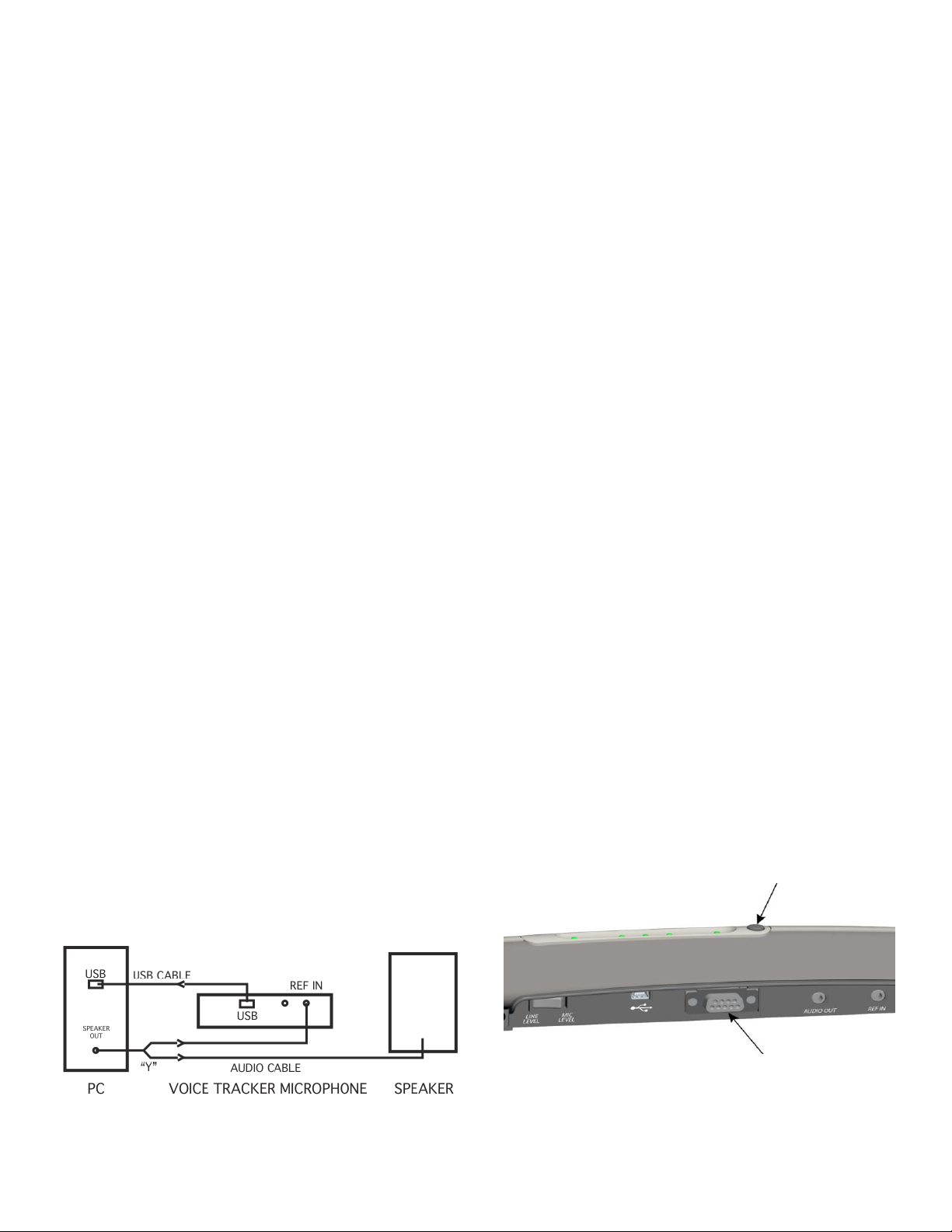
A view of the connections for full duplex operation is
shown in figure 1. Note: connection can alternatively be
made thru analog cable from audio out jack
Setup for Analog output
If the Voice Tracker II is to be connected to devices that
require an analog signal (such as a handheld recorder or
video camera), its output is available in analog format at
mic level or line level through the “Audio Out” 3.5 mm
jack. The included audio cable could be used for this
connection if AEC isn’t used; otherwise, a 2nd audio
cable will be required.
If analog output in used, power needs to be provided by
connecting the USB cable to an optional USB wall power
converter, like our part 201. Getting power from a PC
can introduce noise in the analog audio signal
The toggle switch on the unit allows selection of mic
level or line level analog output, or close range/long
range USB audio output. If the switch is used to change
output levels, the Voice Tracker II must be rebooted
(powered off and then on).
Position Lights
The green position lights provide feedback on the
operation of the array. They indicate where the array’s
listening beam is pointing. When the array recognizes a
relevant sound, one of the 5 lights will be illuminated.
For example, if a talker is directly in front of the array,
the middle light will be illuminated. If the talker is to one
side, a light on that side will turn on. If the talker moves
across the field of view of the array, the lights will track
the talker’s motion. When two users are sharing the
array, the light will indicate the direction of the active
talker. When there is no active talker, the LEDs will be
off.
Controls
The Voice Tracker II has a pushbutton mute switch.
Press the button once to put the Voice Tracker II into
mute mode. The five green LEDs will blink
(continuously), indicating that the microphone is in mute
mode. Press the button again to return to microphone to
listening mode (the LEDs will indicate the active talker).
MuteButton
Figure 1 – Audio and AEC Connections
DB9
Figure 2 – Mute Button and Connectors
Positioning
Page 2

The Voice Tracker II scanning listening beam can pick
up sound from a full 360° field of view. However, the
Voice Tracker II is more sensitive to sound in front than
from behind.
For use with a PC (speech recognition or VoIP
telephony/conferencing) the Voice Tracker II can be
placed under or next to the display.
In a conferencing application, it is best to place the Voice
Tracker II on one end of the table with its front pointing
towards the far end.
Voice Tracker II can also be mounted (with an optional
bracket) on walls or on the ceiling to reduce clutter.
To maximize acoustic echo cancellation, use only one
loud speaker, and place it to one side of the Voice
Tracker II.
Talker location signal
Since the Voice Tracker automatically points a “listening
beam” at the loudest talker, it knows the location. This
signal is made available as a digital word through the
DB9 connector (cable is optional).
The RS 232 serial output signal consists of 8 bit words,
no parity, 1 stop bit; commonly referred to as 8,N,1.
2400 baud.
Data is between 0 and 250, corresponding to talkers
from the far left in front of the Voice Tracker (0) to the far
right (250). If the talker is directly in front of the Voice
Tracker, the data will read 125.
Note that the Voice Tracker picks up sound from the
behind. So a reading of 125 could mean the talker is
directly in front or directly behind the Voice Tracker.
When the Voice Tracker detects no talker, the location
signal reads 255.
The user will have to create application SW to calibrate
these signals into degrees.
Applications
Speech Recognition
Since the Voice TrackerTM operates differently from other
types of microphones or audio input devices, you should
retrain your speech recognition software (enroll a new
user). Be sure to select USB Array Microphone during
the “New User” setup. Personalized vocabulary can
usually be transferred to the retrained “User”.
Conferencing
The Voice Tracker II can be connected to non-PC-based
conferencing systems. Some of the systems require an
XLR (balanced) connection. An inexpensive adapter (like
the Radio Shack 274-017C Adapter/Transformer) can be
used to convert the Voice Tracker II’s unbalanced low
impedance output to “balanced” XLR.
Meeting Recording
The Voice Tracker II can be connected to a PC with
meeting recording SW, or directly to a handheld digital
recorder using the 3.5 mm analog audio output jack and
wall power supply.
Security Monitoring
The Voice Tracker II can often connect directly to the
microphone input jack of video cameras/dial-up/Internet
transmission systems. Choose the analog output level
that matches the camera requirements.
Trouble Shooting:
Acoustic echo cancellation.
If the ref signal is too strong or too weak, AEC will not
work well. Make sure the playback level in the PC is set
to midscale. Turn up the volume on the (external)
speaker itself if more loudness is desired.
No Audio
Check whether the LEDs track the talker. If not, reboot
(repower). If so, the problem is probably in the computer
setup. Make sure it is looking for recording input where
the Voice Tracker is connected (USB, Mic in, or Line in).
Analog or USB Audio too strong.
Make sure the output level switch is set to mic level
Analog or USB Audio too weak.
Make sure the output switch is set to line level
FCC Compliance
This equipment has been tested and found to comply the
limits for a Class A digital device, pursuant to part 15 of
the FCC rules. These limits are designed to provide
reasonable protection against interference when the
equipment is operated in a commercial environment.
This unit generates, uses and can radiate radio
frequency energy, and if not installed and used in
accordance with the instruction manual, may cause
harmful interference with radio communications.
Changes or modifications not expressly approved by
Acoustic Magic could void the user’s authority to operate
the equipment.
35 Peakham Road
Sudbury, MA 01776
www.ACOUSTICMAGIC.com
 Loading...