

Acoustic 450 Owner's Manual
Note: This owner’s man ual for the Acoustic 450 has bee n reconstructed from digit al scans of an
original manual, run t hrough OC R soft ware an d rec onsti tuted i nto a pri ntable docum ent. Ev ery eff ort
has been made to retain the content integrity of the original
document. Thanks Julien
for the files.
OWNER'S MANUAL
control corporation
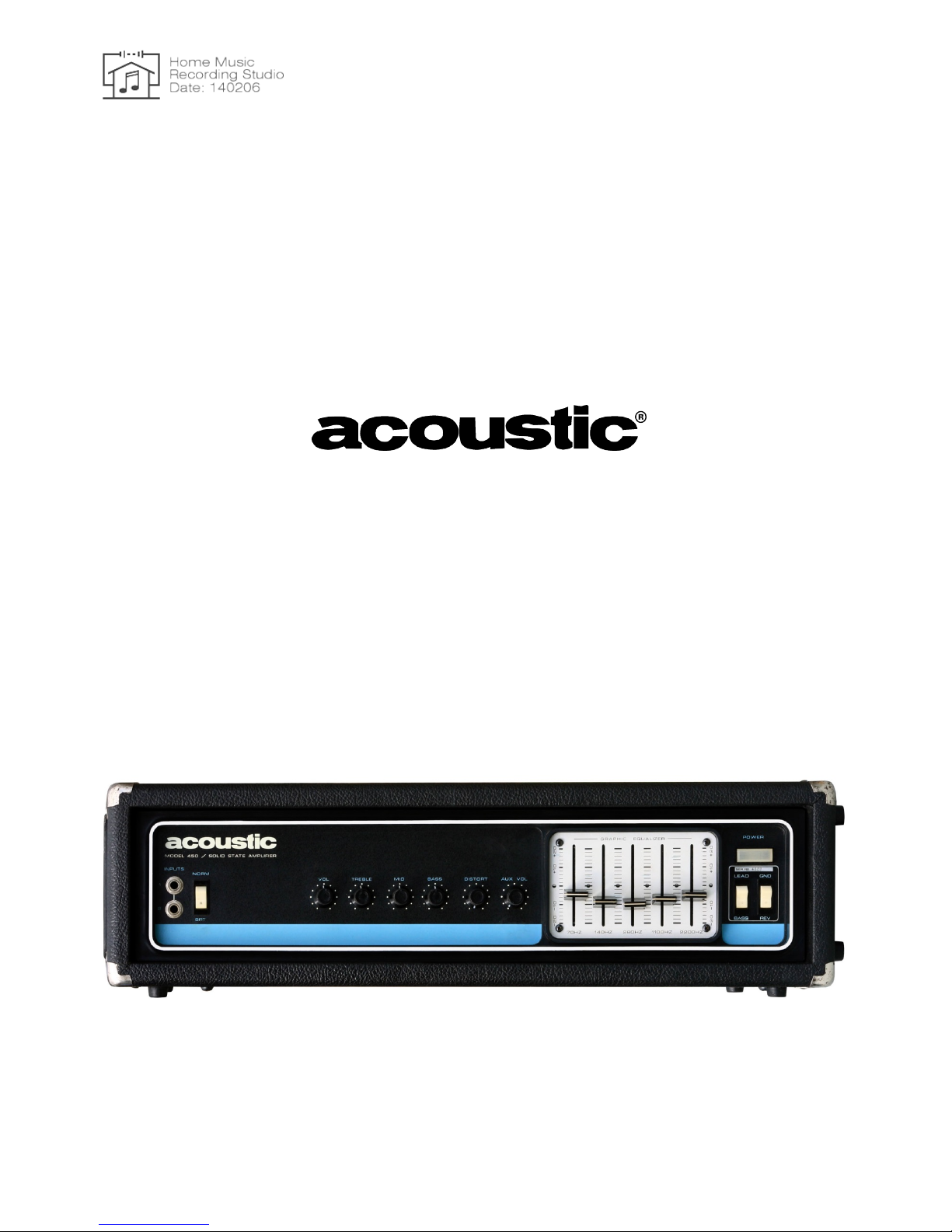
MODEL 450
LEAD / BASS AMPLIFIER
acoustic control corporation
7949 Woodley Avenue
Van Nuys, Ca. 91406
(213) 997-6631
1 P/N 410134

A WORD TO ACOUSTIC
AMPLIFIER OWNERS
We would like to take this opportunity to thank you for choosing an ACOUSTIC product and to assure you
of our continuing interest in your musical pleasure and satisfaction.
This manual has been prepared to acquaint you with the proper operation of your amplifier and to provide
important information as to its many capabilities. We urge you to read it carefully and follow the
recommendations contained to help assure the most enjoyable and trouble free operation of your amplifier.
When it c omes to service, remember than an authorized ACOUSTIC Service Center knows your amplifier
best and is interested in your complete satisfaction.
2 P/N 410134

TABLE OF CONTENTS
Page
ACOUSTIC LIFETIM E WARRANT EE
4
GENERAL DESCRIPTION 5
MODEL 450 - SPECIAL FEATURES 6
1. Lead / Bass Selector Switch 6
2. Special Output Circuit Configuration 6
3. Auxiliary Volume Control 6
4. Use Outside the United States
6
FRONT PANEL VIE W 7
OPERATION OF CONTROLS and CONNECTIONS 8
CONNECTIONS 8
1. Input 1
8
2. Input 2 8
3. Bright Switch 8
4.
Volume
8
5. Treble 8
6. Mid-Range
8
7. Bass 8
8. Distortion Cont rol
9
9. Auxiliary Volume Control 9
10. Ground Reverse Switch
9
11. Lead / Bass Selector Switch 9
12.
Power On /
Off Switch
9
13. Graphic Equalizer 10
How the Graphic Equalizer Works
How to Use the Graphic Equalizer
REAR PANEL VIEW 11
14. Speaker Output Jack 1 12
15.
Speaker Output Jack
2 12
16. Booster Output 12
17. Line Outputs 12
18. Accessory Jack 13
19. Footswitch Connector 13
20. Fuse 13
21. AC Convenience Outlet 13
22. AC Line Cord 13
A NOTE ON SPEAKER IMPEDANCES 14
MODEL 450 PHYSICAL SPECIFICATIONS 15
MODEL 450 ELECTRICAL SPECIFICATIONS 16
AMPLIFIER LINE VOLTAGE REQUIREMENTS
FOR OPERATION IN U.S.A. AND FOREIGN COUNTRIES 18
3 P/N 410134

ACOUSTIC LIFETIME WARRANTY
Acoustic Control Corporation guarantees its products to the original purc haser to be free
from all
defec t s in
materials and workmanship.
THIS LIFETIME GUARANTEE IS VALID ONLY IF THE WARRANTY REGISTRATION CARD IS
COMPLETED AND MAILED TO ACOUSTIC WITHIN 10 ( TEN) DAYS FROM THE DATE OF PURCHASE.
Acoustic Control Corporation will validate the Warranty and return it to you for your files. The card MUST be
validated for your warranty to be in effect.
Should an Acoustic product require service, the purchaser must take the product to an authorized
ACOUSTIC Service Center for repair in order for the Warranty to be effective. A list of these centers is
provided in the back of this manual. Once the produce has been delivered to the Service Center, all repairs
will be made free of any charge to the original purc haser, provided the product has not been misused or
mishandled.
IMPORTANT
It is necessary for your ACOUSTIC product to be registered in the event it should ever req uire service . In
order to register your new Acoustic product and receive the Acoustic Life-Time Warranty, fill out both
sections of t he W arranty card and return it to Acoustic within 10 (ten) days of the purchase date. PLEASE
PRINT LEGIBLY. The first part of the card will be kept in our files. The second part will be validated and
returned to you. The card must be validated for your Warranty t o be in effect.
To avoid unnecessary expense, an owner who desires service on a piece of equipment must always bring
the validated Warranty card to the authorized Acoustic Service Center when the equipment is taken there.
If the card is not presented at that time, a phone call, at the owner's expense, will have to be made to the
factory to establish a valid Warranty on the equipment.
4 P/N 410134

GENERAL DESCRIPTION
ACOUSTIC'
s Model 450 is a versatile g uitar amplifier with many special feat ures that
produces
170 Watts
RMS power into a 4 ohm speaker
with less than 5% distortion. The Lead/Bass
switch located on the front
panel is unique in that it allows the amplifier to be used as either a lead guitar or a bass guitar amplifier.
Besides having a quality sound and a powerful sound system, the Model 450 excels in flexibility due to its
advanced engineering. The location and function of each control is clearly described in this manual. To
utilize the full capability of this instrument, it is again recommended that you READ THIS OWNER'S
MANUAL thoroughly.
5 P/N 410134

MODEL 450-SPECIAL FEATURES
1. LEAD/BASS SELECTOR SWITCH
The LEAD/BASS switch located on the front panel allows the amplifier t o be used as either a lead
guitar or a bass guitar amplifier. The amplifier in the LEAD switch position is a wide-band flat
amplifier. It reproduces fundamental tones plus harmonics. This is most desirable when playing a
lead guitar. When used in the BASS position, the harmonics are restricted. All harmonics beyond
1200 Hz are de-emphasized, a desirable characteristic when playing a bass guitar. The
LEAD/BASS selection is made in the output section of the circuit which makes the LEAD/BASS
conversion effective even when the amplifier is being overdriven or when it is used in the distort
mode.
2. SPECIAL OUTPUT CIRCUIT CONFIGURATION
This provides constant power into the speaker, especially at low bass f requencies, to produce solid
bass characteristics and to augment the higher harmonic frequencies.
3. AUXILIARY VOLUME CONTROL
This control allows you to pre-set two different volume levels and switch between them with the foot
switch.
4. USE OUTSIDE THE UNITED STATES
If you wish to use your amplifier outside the United States, voltage selection can be made with slide
switches that are located inside the back of the amplifier. (You must r emove the cover to make the
voltage selection.) The amplifier's various operating voltages are 107V, 120V, 210V, and 240V, all
at 50 or 60 Hz.
CAUTION: Even though the switches are clearly marked, it is suggested that your dealer's service
department make the adjustment.
6 P/N 410134

7 P/N 410134
 Loading...