

Page 1
MODEL,
ONE
MODEL
MODEL
MK
121 & MK
A
Electrostatic
OWNER’S
ODEL
ONE
TW
r
THREE
+
ONE
141
VERSIONS
USTAT
Systems
MANUAL
AND
ASSEMBLY
INSTRUCTIONS
Page 2

TABLE
OF
CONTENTS
Specifications
Limited
Introduction
Registration Cards
Packaging
Fusing
Assembly Instructions
Sub-woofer Connections and Aacemenf
Recommended
Warranty Statement
...............................................................................
Distance from Wall
Placement Within the Room
Angling
Acoustical
Phasing
Electric Feedback
........................................................................
............................................................
..........................................................................
..........................................................
...........................................................................
..............................................................
Set-up
and speaker Placement
...............................................................
.......................................................
.......................................................................
Properties
of the
Walls
..................................................
.........................................................................
................................................................
.........
............................................
1
1
2
2
2
2
3
-
4
4 - 5
5
5
5 - 6
6
6
6
Cleaning
Removal
High Frequency
Schematic
Parts
Schematic
Parts
.............................................................................
of
Interface
.
List
-
MK-124
-
List
-
MK-141
for
Balance
MK-421
.................................................................
...................................................................
MK-141
................................................................
..................................................................
all
Models
....................................................
..............................................................
7
7
7
8
9
10
41
Page 3
SPECIFICATIONS
MODEL
15'
Nominal Impedance: 4 ohms; Power Consumption: 5 Watts (120V,
11
37
ON€
-
Frequency Resoonse: 30-1
in a 14’
"x
3 1/2"; Bass Model Dimensions:
Lbs (Bass Module)
x
18'
room. (music Peaks); Minimum
18 1/2"
8kHz
x
18 1/2" x
+/- 3 dB; Sound Pressure Level: 108 dB measured
4
8 1/2";
Power
Requirements:
Weight:
65
75
Watts/Channel;
50/60
Hz);
Dimensions:
Lbs. (Speaker and Interface).
72" x
@
MODEL
22
dance: 4 Ohms; Power Consumption:
MODEL
x
Impedance:
Weight 98
MODEL
26‘
dance: 4 Ohms; Power Consumption:
1 + 1 - Frequency Response: 35-20kHz +/- 3 dB; Sound Pressure Level:
room. (Music Peaks); Minimum Power Requirements:
5
watts
(120V,
x
3%”; Weight:
THREE
22
room. (Music Peaks); Minimum Power Requirements:
4
2
2 - Frequency Response: Sound Pressure
room. (Music Peaks); Minimurn Power Requirements:
The
72
-
Frequency Response: Sound Pressure
Ohms;
specified
Power
Consumption: 5 Watts
and
5
Watts
50/60
(
108
db
@
100
Watts/Channel; Nominal Impe
Hz);
Dimensions: Model
40
db@
70
Dimensions:
db
22‘
Hz);
Dimensions: 94
x
18'
4
28
20”
in a
in a
in a
x
14'
14
x
Impe
x
-
x
x
-
PRODUCT.
OR
or
Page 4

INTRODUCTION
Congratulations on your purchase
Please review the entire owner's before uou begin to assemble your new speakers
assure
the
you
room,
of
reaching the speaker's full potential. When assembled, placed in
and used
with
years
of
fhe
proper
listening enjoyment.
of
electronics, the electrostatic loudspeakers
ACOUSTAT
ELECTROSTATIC
LOUDSPEAKER
SYSTEM.
REGISTRATION CARDS
days
purchased yournewspeakem.
allow
Any
additional you provide
music
lovers
everywhere the
This
card
does not
of
updafes and other product news
finest
audio components today.
that
would be
aid in continuing
interest
to
PACKAGING
SAVE
ALL
PACKAGING
pieces d equipment, and
the original packaging materials may
must
Your electrostatic are finely
be
property whenever
be
obtained from
at
a
is
necessary.
FUSES
All
ACOUSTAT
located on the
loudspeakers utilize
rear
only
those
of
panel dthe
can
fuses In the audio signal path. This
base
of each replacing
be
used
or
the
may
become invalid.
to
of
to
bring
ONLY
is
LOW-FREQUENCY TRANSFORMER
Before
tag) and
assembly, locate low tap terminal
that
setting
is
correct for
MI
M3
This determines
setfing
bass
response that
bass
TAP
is
weaker
(FULL
Red
Wire to Red Lug
Red
Red
to
to
for
2
RANGE MODELS ONLY)
(identified
per
below:
Orange Lug
Yellow
the
Lug
different speaker models.
than normal.
by
a
Page 5
3
Page 6

ASSEMBLY
INSTRUCTIONS
ALL MODELS
PLEASE READ
For
assembly you
attached
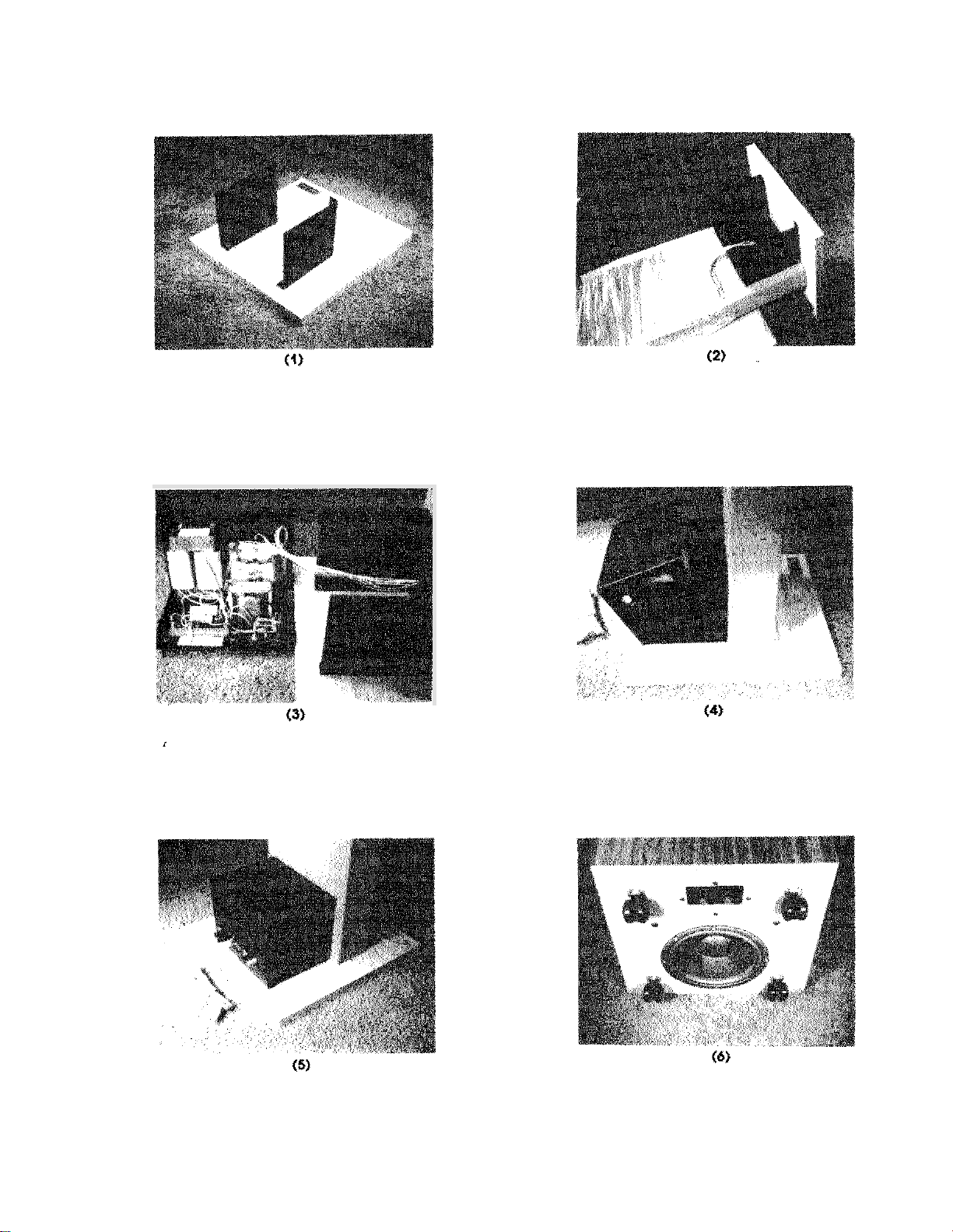
Remove bases, speaker panels and interface from their packing cartons. To
COMPLETELY
will
to
the interface cord.
BEFORE
require a targe Phillips
YOU
ASSEMBLY.
type
screwdriver, and the small
the
Using the small hex wrench provided, the disassemble the side plates from the main
2.
Set a speaker base on the
3.
shown
Lay
4.
The frapped
the
(1
speaker
lower
5.
the side plates
Standing
5.
speakerasshown
speaker panel. Separate the three wire bundles
end: the
7.
Referring
board
blue
thumbscrewseveral
Repeaf
back the hole
plates. keeping
four
the
9.
Position
backwalland at
'SPEAKER
outlet.
on
of
dot
hex wrench provided
of
the panels
securing them
GENTLY
air
under fhe panel can rupture fhe speaker diaphragm.
end panel,
to
the in the speaker back panel. Tighten all screws securely.
the
compfeted speaker up vertically. position the interface assembly the
(3).
BLUE
group
to
diagram
the interface
the spacer
this procedure
fhe assembled speaker systems
With
in
the speaker panel. on the side
for
assembly.
required
floor.
nameplate
two
slot
on the
or
Locate harnessemergingfromthe the
the blue hook
insert pin plug
Aff
support
ach
floor,
BLUE
below
for
the
hook on fhe
OUTSIDE
(5).
side
up. the side plates
head
screws
it
on the box.
into
per
the
plate.
Leave
with the plug on the
on
(RED
group) into the
hook
to
the on the right
the thumbscrew, and the word
side
side
the
plates,
room,
GENTLY
RED
washerand tighten
of
the circuit board.
feeding the
as
shown
two
aligning
WHITE
socket on circuit
side
or
later.
on
up.
DO
Have
a helper
gmup,
'BLUE'.
(4) & (5).
three
least
section
(RED)
for
of
the
terminal
(BLACK)).
on
speaker
the cord
is
connected
info
an wall
to
(RED)
the base as
NOT
DROP!
raise
with
the
wiring
from the
terminal
GENTLY
connections
the back
layfhe woofer module on
of
1411
B
INTERFACE
its
side,
(6).
Connect the woofer on the the terminals labeled 'woofer' on
the
speaker inferface. Repeat this procedure
(see
section
SYSTEM
exposing the woofer cone and
for
the right
on
phasing
4
in
the placement
left
and right terminal
section
of
the manual.)
Be
sure
Page 7

FAX
704 331 0402 LEE NICHOLS ARCH
When complete, there
bass
module
is
While
speakers, some room arrangements may not
bass
DIAGRAM”.
placements
NOTE
few days
generally advisable to place the bass module
performance when the module was placed the shaded area in
of
be
a
and a right cable to the single bass module. Return
its
operating (woofer cone facing down).
a central location
to
walls
permit
corners
this. Our listening tests revealed balanced
result in uneven response, with these
of
-
in electrostatic portion
produce sonic improvement and an increase in efficiency.
RECOMMENDED SET-UP AND SPEAKER PLACEMENT
DISTANCE
Leave
fromf hecenterofthe
a
walls.
PLACEMENT
By
placing speakers far apart against a tong
window” without loss of center
with the listening posifion at
FROM
at least
WALL
three
feef
THE
from
ROOM
to
at
All.
Race the speakers
apex. (Refer
the
two
to
rear
Figure
wall.
from
so
IA).
To
determine
the side
you
of
wilt
obtain the largest “listening
“PLACEMENT
this
distance, measure
the speakers
an equilateral triangle
to
the side
LOW
of
the
room,
projecting into
two
retain
In
this
case,
ANGLING
Angle the speakers with the panels directed toward the listening position. There are
listening
OR
Angle the speakers
feet suggested distance
it
is
to
the side (Refer
is
slightly in
window.
to
use the space to separate the
of
the
you
to
move your listening position with
so
that the “apex”
possible bass
from
the stde
to
Figure
listener. (See Position
is
slightly behind listener.
will
be
of
the speaker tot
A).
with
the rear
obtained.
This arrangement
may be impossible to
he
wall
minimum change;
(See
of
in
a
Position
5
RESPONSE
the speakers
narrow
two
general
the widest
room.
This
Page 8

arrangement reduces the "Listening window," but provides a more focused sound.
to
achieve this "apex" position.
NOTE
Neither position
is
in cases other. Personaf taste and room placement
is
the best
for
you. Experiment!
requires
ACOUSTICAL
A
speakers such
more
precise imaging and superior focus
PROPERTIES
OF
end-dead end sef-up in the listening room can sometimes improve the sonic
of
a
speaker This can
as
fhe walls using a
THE
SOLID LINES
ANGLING ONLV WHEN THE PANELS
PENDICULAR TO THE
THAT
APEX
DASHED LINES REPRESENT
RADIATION
SPEAKERS
THE
FRONT
DICULAR
A
THE
SPEAKERS
IN SLIGHTLY
ARE
SHOWN
OF
THE
SPEAKERS
SHOWN
OF
ARE
ME
THE
THE APEX
HAVE
PLANE
TO
THE LISTENER IN A ROOM
WOULD MELD
TO
ACHIEVE
WOULD
TO
ARE
DRAWN WITH
PERPEN
IN
IN
TO
BE
ANGLED
THE
PER-
SONIC
THIS
THE
WALLS
-
B
heavy
be
accomplished by using materials
from
your
speakers. a listening test before you
blanket suspended while
I
I
I
you
listen.
I
to
preserve the correct absolute phase throughouf the system,
the signal to the air. The ensures that both vocalists and
(+)
to
black.
ELECTRIC
FEEDBACK
Electrostatic speakers produce a strong electric Reld which can the operation
level
low
electronic circuitry
this reason, the leads and the phono inputs
six
to
kept at Least
WARNING! DO
eight
NOT
apply audio
panel bias! Connection
or bypass
frequency
receptacle. Either the above
if
close
of
power dissipation and decreased headroom in system.
feef
from
the nearest
to
switched
the interface
proximity. This can in feedback well above the audio
of
the preamplifier should be
to
the intelface the
is
not
recommended.
Power removed, hence
DO
NOT
exceed
fuse
is
by the
6
-
om
--)
of
any
For
no
ratings
low
Page 9

CLEANING
Speakercloth may be cteoned with anycommercial oranycleaner designedfo
be
used with polyester knit
be
removed
discharge the panels:
Use
cleaner such as
from
the speaker, the following procedure
K2R
for
concenffated spots.
is
necessary to
UNPLUG
amplifier.
Remove the four
2.
3.
4.
5.
6.
WARNING: High static
procedures
Follow
diagram
center tap and
adjustment, tap
that
the interface unit on the Boor directly behind the speaker, being careful
wire
the three
Remove the center
NOT
GRAB
Loosen the
will
-
FREQUENCY BALANCE
frequency balance
the for
groups
PLUG!
result
locate the high frequencybatance resistor in the interface assembty. Loosen the
or
strain the wiring harness.
RED
pin plug.
Touch
thumbscrews and remove the hooks.
in
an annoying but shack.
is
This
level can
“REMOVAL
or
right, according
from
Hold
the wire an inch behind the pin and
to
either the
in
the charged panel.
CONTROL
for
be
adjusted for situations
OF
INTERFACE
to
the diagram for increase or decrease.
NOTE
optimum performance and stereo imaging be
IDENTICALLY.
speaker
BLUE
or
WHITE
optimum
in
fhe following manner.
at fhe end
of
leads from the
not
to unpfug
pull.
DO
to
fallow these
a
room
After
SURE
to
Page 10

\
N
W
W
N
m
m
Page 11

c2
c3
c4,
R2.
R4
R3
6
ohm
50
ohm
500
ohm
M
ohm
List
-
MK-121
220
3300
w
20
w
2W
slider
Polystyrene
Polypropylene
Non
-
polar
6
Polypropylene
6KV
‘TI
T2
F2,
F3
Acousfaf
5
Amp
Amp
High
Transformer
Hi
Frequency
21
Lo
Frequency Transformer
diode
9
Page 12
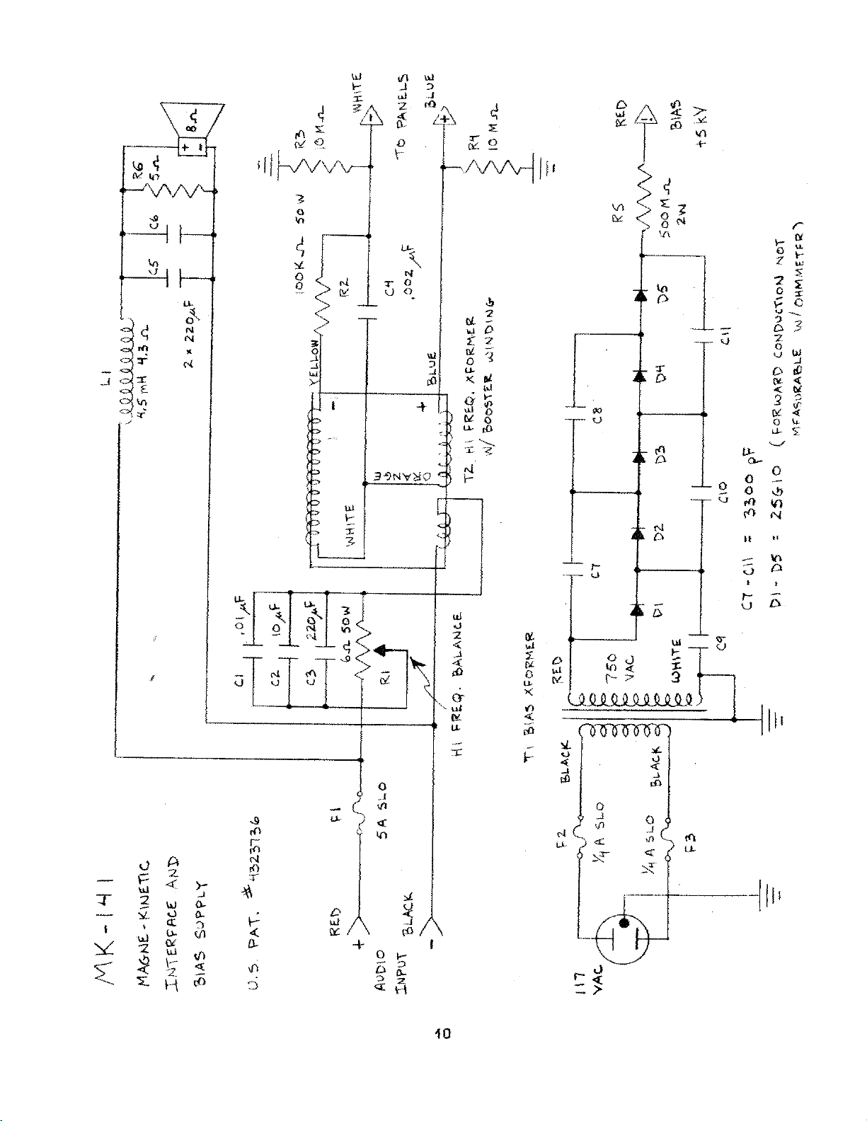
Page 13

FAX 704 331 0402 LEE NICHOLS ARCH
Component
c2
c3
C5,
C6
CI
R5
Values
0,
6
500
5
2561
ohm
K
M
ohm
List
ohm
ohm
-
40
220
220
3300
50
w
3w
2w
20
w
High
UF
slider
diode
6
Ceramic disc
Non
-
polar
3
Ceramic
disc
F2,
Air
45
F3
ohm
Bias
Transformer
core indicator
Page 14

Terrace
phone:
Fort
33315
 Loading...