

Page 1
4PMMNL Abridged User Guide
VT6103
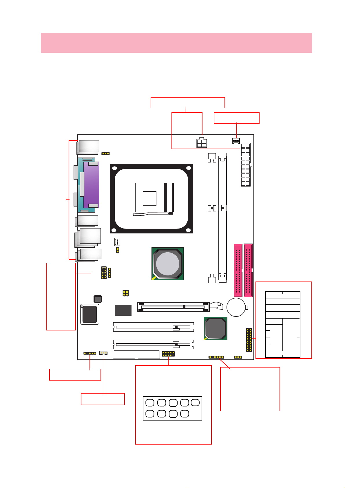
1. 4PMMNL Component Layout
Connect 2 Power Connectors
to Power Supply to boot system
Fan Connector for
CPU cooling Fan
Back Panel
Connectors
J16
Front Audio
Pin 1 Mic In
Pin 3 VREFOUT
Pin 5 FR-IN
Pin 7 (NC)
Pin 9 FL-IN
Pin 2 Aud GND
Pin 4 Aud Vdd
Pin 6 FR-OUT
Pin 8 (Key)
Pin 10 FL-OUT
BIOS
IR1
J16
2
Audio
Codec
WOL
J15
FAN2
J3
9
CD-IN1
1
J7
RTL
8100BL
VT6103
FDD Connector
Socket 478
PCI Slot
PCI Slot
mPGA478B
VIA
P4M266A
AGP Slot
Power
USB2
+12V
DDR 266/200 SDRAM
VT8235
DIMM Slot
VIA
J17
FAN1
DIMM Slot
ATX Power
IDE2
Battery
JBAT1
IDE1
Front Panel Connectors
20
18
16
(+)
14
HD LED
12
20219
Fr. Panel
(V oid)
10
8
6
SPEAKER
(+) (+)
4
PS SW
2
1
RST
19
17
15
13
11
9
7
5
3
PW LED/Keylock
(+)
1
IR Receive/Trtansmit
Connector
Wake-up on LAN
Connector
USB2 Pin-header
USBDT5-
+5V
2
1
+5V
USBDT4-
USBDT5+
GND
GND
USBDT4+
GND
J17: Smart Panel III LED
Pin 1 GPIOC
Pin 2 N/A
Pin 3 GPIOE
Pin 4 GPIOD
Pin 5 GPO0
Pin 6 GND
910
Page 2
2. 4PMMNL Specification and Features
• CPU
Socket 478 for Intel P4 CPUs;
Supporting FSB 400/533MHz;
• Memory
Supporting DDR266/200 SDRAM with 2 DDR DIMM slots up to 2GB module size;
• System Chipset
North Bridge P4M266A; South Bridge VT8235;
• Smart BIOS
Full ACPI, APM, DMI, Green, PnP, CPU FSB, Multiplier Ratio & Boot media Selection supported;
• Integrated Graphics
1x VGA connector and 1x AGP slot integrated;
• LAN Controller Integrated
• Six USB 2.0 Ports supported
• 2x PCI slots integrated
• 2x UltraDMA 66/100/133 IDE ports
• 6-channel AC’97 Codec integrated
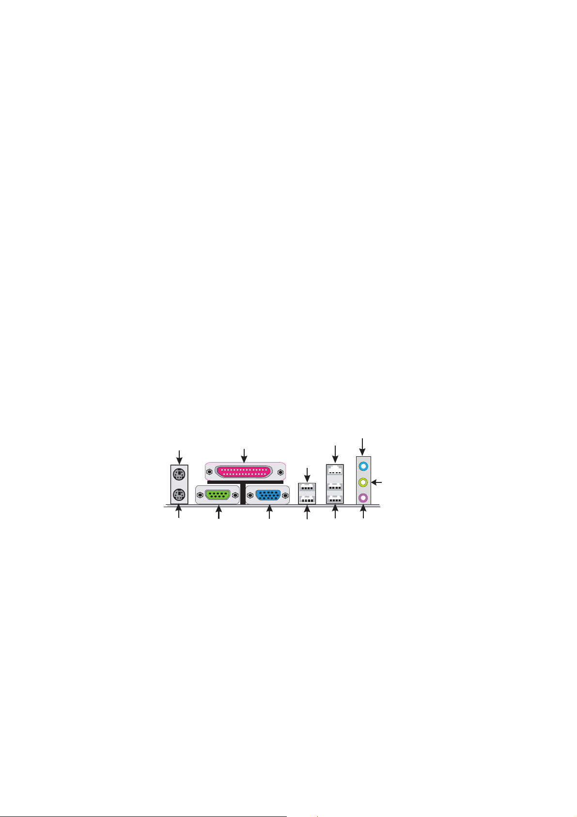
• Back Panel
6xUSB ports; 1xVGA port; 1xCOM port; 1xParallel port; 1xPS/2 keyboard port; 1xPS/2 Mouse port;
1xLine-in; 1xLine-out; 1xMic;
PS/2 Mouse
PS/2 Keyboard
COM 1
Printer Port
VGA
USB
USB
Optional
USB(2 ports)
RJ45
Line-In
Line-out
Mic
Page 3
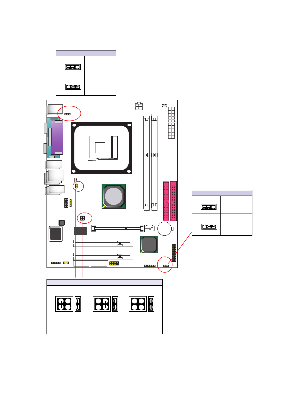
3. Jumper Settings
VT6103
J15: KB/Mouse Wakeup
1-2 closed
1
Enabled
2-3 closed
1
J16
Audio
Codec
BIOS
J15
CD-IN1
VT6103
FAN2
J3
Disabled
(Default)
J7
RTL
8100BL
Socket 478
mPGA478B
VIA
P4M266A
AGP Slot
+12V
Power
FAN1
ATX Power
DDR 266/200 SDRAM
DIMM Slot
DIMM Slot
IDE1
IDE2
JBAT1:Jumper Clear CMOS
Battery
1-2 closed
1
2-3 closed
1
Normal
(Default)
Clear CMOS
PCI Slot
PCI Slot
WOL
IR1
FDD Connector
J3 & J7 : CPU Clock Select
J7 J3 J7 J3
2
4
2
1
66 MHz
CPU
1
3
(default)
2
4
1
3
100 MHz
CPU
JBAT1
20219
Fr. Panel
1
VIA
VT8235
J7 J3
2
4
1
3
J17
2
1
USB2
2
1
133 MHz
CPU
Page 4
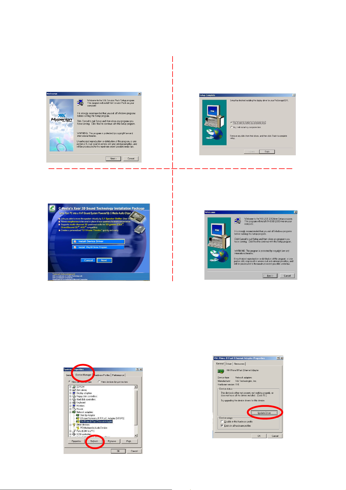
4. Drivers Installation
When starting to install drivers or utilities, if you are prompted to choose a proper motherboard model,
please click on “4PMMNL” for this motherboard.
(1). VIA 4-in-1 Service Pack:
Choose this auto-run program in you Driver CD,
and the Setup Program will guide you through
the whole VIA 4-in-one Service Pack Setup.
(3). C-Media Audio Codec:
This motherboard comes with C-Media Xear 3D
CODEC . Y ou can find the Audio driver from this
Auto-run menu.
(2). VGA Driver :
Choose this auto-run program in you Driver CD,
and the Setup Program will guide you through
the whole VGA driver Setup.
(4). USB 2.0 Driver Setup:
Choose this auto-run program in you Driver CD,
and the Setup Program will guide you through
the whole USB 2.0 driver Setup.
(5). LAN Driver Setup:
LAN drivers can be installed into your operating system either automatically by the auto-run setup program or
manually by user. Follow the following illustrations to install LAN driver for your operating system:
1. If your system (e.g. Win2K or WinXP) detects the onboard network hardware, it will go on find out the
proper LAN driver and install it right away.
2. If your system is Win98 or if you want to install the
LAN driver by yourself, please enter the "Device
Manager" of your Windows system. You can see
that the "VIA Rhine II Fast Ethernet Adapter is not
set up yet. Click "Refresh" to set up the driver.
2. Click “Update Driver” to continue, and then
follow the instructions from the Setup windows
to finish setup.
[Note]
If the OS is windows 98, the Lan driver
located at Optical Drive:\Driver\Lan\VT6103
 Loading...