

ACORN AQUA A511103B, A511403B, A511103P, A511403F, A511403P Installation, Operation And Maintenance Instructions
...Page 1
INSTALLATION, OPERATION AND MAINTENANCE INSTRUCTIONS
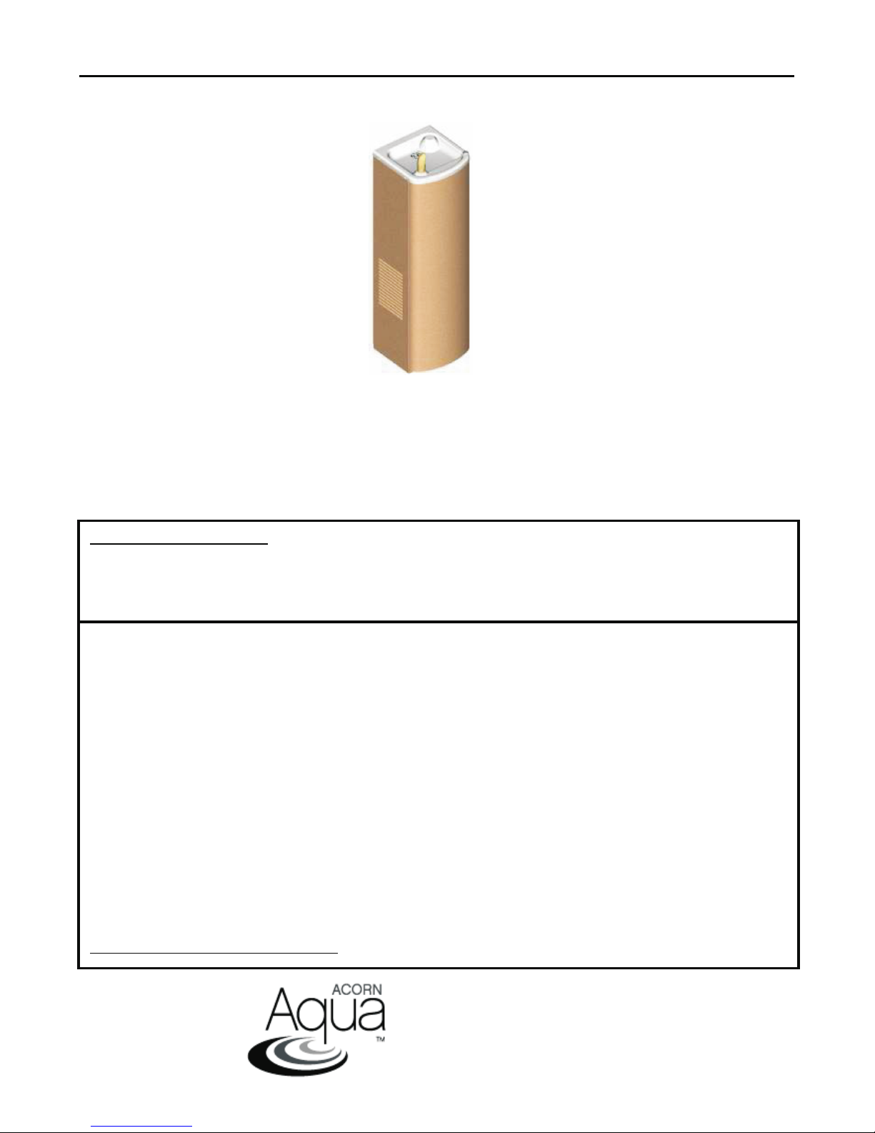
AquaCold
Compact Free Standing Water Coolers
A511103F / A511103B / A511103P / A511403F / A511403B / A511403P
A511105F / A511105B / A511105P / A511405F / A511405B / A511405P
A511110F / A511110B / A511110P / A511410F / A511410B / A511410PF
TECHNICAL ASSISTANCE TOLL FREE TELEPHONE NUMBER:
1.800.591.9360
Technical Assistance Fax: 1.626.855.4894
NOTES TO INSTALLER:
1. Please leave this documentation with the owner of the fixture when finished.
2. Please read this entire booklet before beginning the installation.
3. Check your installation for compliance with plumbing, electrical and other applicable
codes.
LIMITED WARRANTY - UNITED STATES & CANADA
Acorn Aqua warrants that its products are free from defects in material or workmanship under normal use and
service for a period of one year from date of original shipment or for 18 months after the date of shipment from the
factory, whichever comes first. The compressor, condenser and refrigeration tubing is warranted for five years.
Acorn’s liability under this warranty shall be discharged solely by replacement or repair of defective material,
provided Acorn is notified in writing within one year from date of shipment, F.O.B. Industry, California.
This warranty does not cover installation or labor charges and does not apply to materials, which have been
damaged by other causes such as mishandling or improper care or abnormal use. The repair or replacement of the
defective materials shall constitute the sole remedy of the Buyer and the sole remedy of Acorn under this warranty.
Acorn shall not be liable under any circumstances for incidental, consequential or direct charges caused by defects
in the materials, or any delay in the repair or replacement thereof. This warranty is in lieu of all other warranties
expressed or implied. Product maintenance instructions are issued with each unit and disregard or non-compliance
with these instructions will constitute an abnormal use condition and void the warranty. Stainless steel must be
protected on jobsite during construction and must be properly maintained after the water has been introduced
into the water cooler or drinking fountain, or Acorn’s limited warranty is void.
LIMITED EXPORT WARRANTY - One year on parts only.
L1001054 Revised: 07/27/10
ACORN AQUA
P.O. Box 3527
City of Industry, CA 91744-0527
United States of America
www.acornaqua.com
Page 1 of 8
Page 2
IMPORTANT
This fixture is intended to dispense water that has been lowered in temperature, but otherwise remains
unchanged by the materials in the water cooler. It is common for electrical equipment to be grounded to
water lines either within a structure or away from it. Every attempt should be made to prevent this kind
of grounding from generating electrical feedback into the water cooler creating electrolysis. Electrolysis
will cause a metallic taste or cause water metal content to increase.
NOTICE
A dielectric coupling must be used to connect the water cooler to the water supply. A nonmetallic
strainer is furnished with this water cooler to meet this requirement.
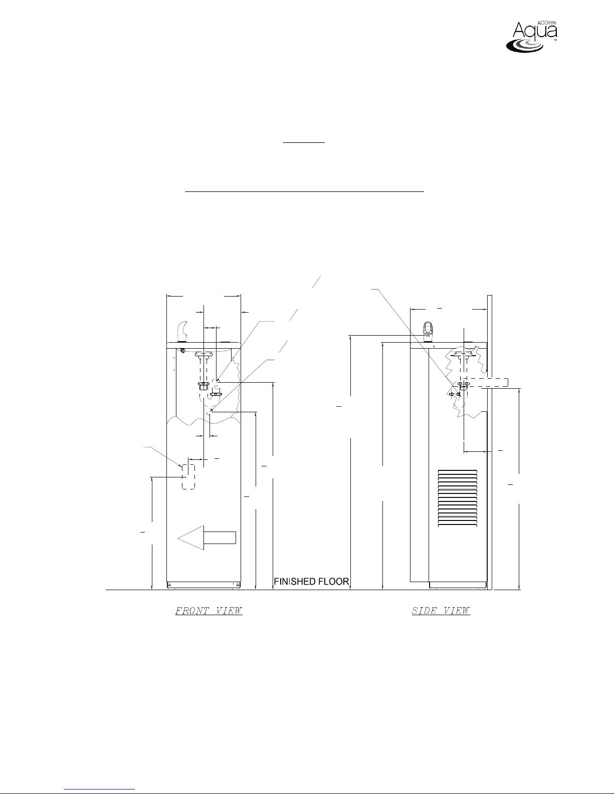
ROUGHING-IN AND DIMENSIONAL DRAWING
Prior to roughing consult with local, state, and federal codes for proper mounting height.
1
1
[32] TRAP
1
[32]
4
[10] OD
4
1
41
8
ORIFICE
HEIGHT
" [1045]
40" [1016]
HEIGHT
RIM
12
1
" [317]
2
C
L
7
3
" [98]
8
1
32
" [826]
2
TAILPIECE
ELECTRIC
OUTLET
12" [306]
1" [25]
6" [153]
2" [51]
C
L
1
2
" [63]
2
28
33
3
" [730]
4
(NOT FURNISHED)
Ø1
WASTE
3
8
COPPER TUBE
SUPPLY
1
" [851]
2
1
18
" [464]
4
GENERAL NOTES:
1. ALL DIMENSIONS ARE IN INCHES [MM]
2. ALLOW 4 INCHES [102 MM] MINIMUM CLEARANCE PER SIDE FOR VENTILATION
3. STOP VALVE, TRAP, & ELECTRICAL OUTLET NOT SUPPLIED.
L1001054 Revised: 07/27/10
AIR FLOW
Page 2 of 8
Page 3
IMPORTANT:
1. Waste P-Trap, Water Supply Service Angle Stop Valve and 2” x 4” Electrical Plug-In Receptacle
to be supplied by others in accordance with local codes. A metallic p-trap must be used for the
drain connection.
2. Provide 4” minimum clear space on fixture sides to allow for proper ventilation through cabinet
louvers.
3. Water supply is 3/8” Outer Diameter copper tube. Waste is 1-1/4” Outer Diameter.
4. Completely flush supply lines of all foreign debris before connecting to fixture. W ater cooler
designed to not cause problems with taste, odor, color, or sediment. Optional water filter (Wf1),
is available should any of these problems arise from the water supply.
5. Do NOT solder tubes inserted into the strainer as damage to the o-ring may result.
6. All burrs must be removed from outside of cut tubes before inserting into strainer or other
components.
7. Power supply must be identical in voltage, cycle and phase to that specified on the cooler data
plate. Electrical outlet and furnished power cord with plug must be used to supply power to
fixture. Do NOT wire compressor directly to the power supply.
8. This unit must be grounded per the requirements of applicable electrical codes.
9. WARNING: Warranty is voided if installatio n is not made following current Acorn Aqua
installation instructions and if components are assembled to the fixture that is not approved by
Acorn Aqua.
10. Fixture operates within water pressure range of 20 to 105 psig. Acorn Aqua will not warranty
fixtures damaged when connected to supply lines with flow pressure lower than 20 psig or
higher than 105 psig. A pressure regulator must be furnished by others on supply line if inlet
pressure is greater than 105 psig.
11. Due to cold waste water, Acorn Aqua recommends that p-trap supplied by installer be insulated
to prevent excessive condensation.
12. Per UPC 609.10- All building water supply systems in which quick acting valves are installed
shall be provided with devices to absorb the hammer caused by high pressure resulting from the
quick closing of the valve. These pressure-absorbing devices shall be approved mechanical
devices. Water pressure-absorbing devices will be installed as close as possible to the quick
closing valve.
INSTALLATION:
1. Provide rough-ins as shown in Roughing-In and Dimensional Drawing.
2. Anchor water cooler to wall through anchor clips on the bottom of the base.
3. Remove the front panel from the water cooler by taking out the screws on each side at the
bottom front, press the panel sides together at the bottom so that front panel clips disengage
from the housing sides and carefully pull forward and down. Set panel aside in a safe place
where it will not be damaged.
5. After thoroughly flushing the 3/8” o.d. supply line, connect water supply to water cooler.
6. Make up 1-1/4” o.d. p-trap waste connection.
START UP:
1. Before connecting power supply and assembling bottom cover to water cooler , but after thoroughly
flushing the supply line and connecting it to the fixture, turn on building water supply and check all
connections for leaks.
2. Air within the water cooler system or the structure supply piping will cause an irregular bubbler
outlet stream until purged out by incoming water. Covering the bubbler with a clean cup (or
similar object) is recommended when first activating water cooler to prevent excessive
splashing. Depress a side or front push bar until steady water stream is achieved
3. If water flow requires adjustment, insert a slotted narrow blade screwdriver in the hole centered
on the underside of the fixture in the knee clearance area up to the flow regulator. Turning
clockwise will increase flow and turning counterclockwise will decrease flow .
4. Recheck all water and drain connections with water flowing through system.
L1001054 Revised: 07/27/10
Page 3 of 8
Page 4
5. With power still NOT connected, carefully manually rotate cooling fan to insure proper clearance
and free fan action.
6. Plug water cooler in to electrical outlet and make sure unit begins to function.
7. Assemble bottom cover to water cooler with screws furnished.
TROUBLE SHOOTING:
IMPORTANT: BEFORE MAKING ANY OF THE REPAIRS LISTED, MAKE SURE THE WATER
COOLER IS DISCONNECTED FROM THE ELECTRICAL SUPPLY AND THE WATER SUPPLY
VALVE IS SHUT OFF.
1. Adjustments
a. Cartridge – The water flow can be adjusted using a slotted narrow blade screwdriver
and turning clockwise to increase flow and counterclockwise to decrease flow .
b. Cold Water Thermostat – The water temperature can be adjusted using a slotted
screwdriver and turning clockwise to make colder and counterclockwise to make
warmer.
2. Compressor Does Not Run
a. Check the electrical receptacle for power and correct voltage. The incoming voltage
must be within 10% of the rated voltage on the serial nameplate.
b. The cold thermostat is accessible by removing the bottom access cover. If the cold
thermostat capillary bulb loses its charge or becomes kinked it will fail in the open
position causing a disruption of power to the compressor. Unplug the water cooler and
using and ohm meter check for continuity across the two electrical terminals on the
thermostat. Install a new thermostat if there is no continuity.
c. Check for loose wires within the compressor box. The incoming power leads must be
connected to the overload and relay.
d. If all components check positive for continuity then test the wiring harness plug for
continuity to see if there is a broken wire within the wiring harness insulation.
3. Compressor Runs – Water Is Warm
a. The most common cause for a water cooler to run without producing cold water is a loss
of refrigerant. The water cooler must be taken to a certified refrigerant technician for
repairs.
b. Make sure the condenser fan motor is operative. The fan blade must turn freely to help
remove the heat of compression.
c. An incorrect refrigerant charge, restriction or defective compressor (not pumping) will
also cause the compressor to run without producing cold water. All these signs indicate
a problem within the refrigeration system and the water cooler must be checked by an
authorized service company.
4. Compressor Cycling On Overload Protector
a. A dirty condenser or a blocked fan will cause a high head pressure and frequent cycling
of the overload protector.
b. Check the incoming voltage to make sure it is within 10% of the serial nameplate rating.
c. A restriction or moisture in the system will also cause intermittent cycling. A certified
refrigeration mechanic should be contacted in this situation.
d. Change the overload or relay if defective.
5. Noisy Operation
a. Check to make sure the fan blade is rotating freely.
b. Make sure the water cooler is correctly mounted to the wall. Absence of the two lower
mounting bolts may cause excess noise and vibration.
c. Check the compressor mounting to make sure the pins and clips are not rattling. If the
compressor appears to be noisy internally, it must be replaced.
6. Restricted Or No Water Flow
a. Ensure water supply service stop valve is fully open.
b. Verify minimum 20 psig supply line flow pressure.
c. Check for twists or kinks in bubbler tubing.
L1001054 Revised: 07/27/10
Page 4 of 8
Page 5
d. Check the water inlet strainer. Sediment from the main supply can get trapped in the
screen along with installation materials such as pipe dope and flux. The screen should
be cleaned and checked on a regular basis and replace if needed.
e. The cartridge valve located in the water control assembly or bubbler can also become
clogged with foreign material. The cartridge valve can only be replaced and not repaired.
f. The water cooler may also develop a freezing condition in which the water will become
frozen inside the evaporator coil. This indicates a refrigeration problem or thermostat
failure in which case the water cooler needs to be checked by a qualified technician.
CLEANING & MAINTENANCE GUIDE:
1. Motors have lifetime lubrication and do not require scheduled maintenance.
2. Excess dirt or poor ventilation will cause the compressor overload protector to turn the
compressor off and it will cycle on and off with no cold water coming out of bubbler. Periodically
clean with vacuum cleaner, air hose or brush the condenser fins and cabinet ventilation louvers.
In environments where dirt and dust is more prevalent, clean more frequently.
3. Periodically remove access panels and clean out in-line strainer.
4. Do NOT use harsh chemicals, abrasive or petroleum based cleaners. Use of these will void the
Acorn Aqua warranty.
5. Exterior panels can be cleaned using mild household detergents or warm, soapy water . Extra
care must be used cleaning chrome plated items and mirror finished stainless steel. They can
scratch easily and should only be cleaned using a clean, soft cloth and mild soap with water or
a mild glass cleaner.
L1001054 Revised: 07/27/10
Page 5 of 8
Page 6
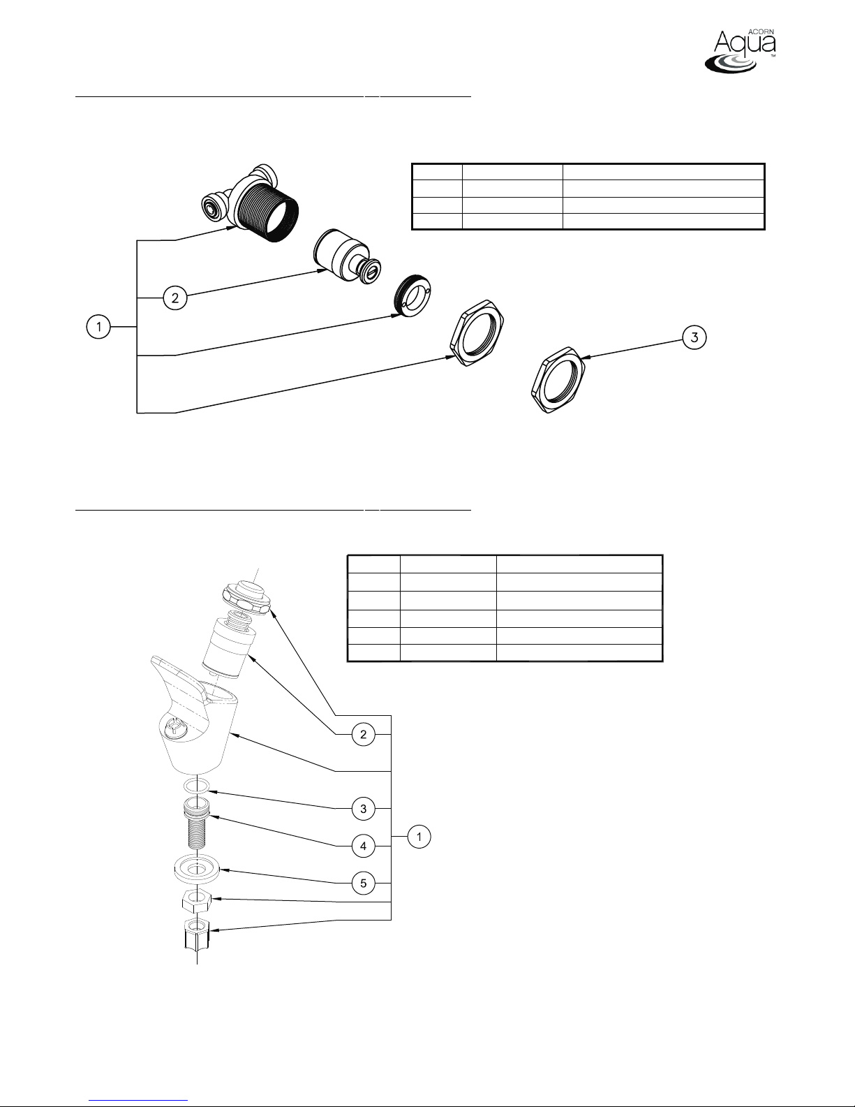
STANDARD CARTRIDGE VALVE PARTS BREAKDOWN
ITEM # PART NUMBER DESCRIPTION
1 7000-050-001 Valve Cartridge Assembly
2 7000-060-000
3 7000-053-199 Jam Nut
Valve Cartridge
STANDARD CARTRIDGE VALVE PARTS BREAKDOWN
ITEM # PART NUMBER DESCRIPTION
7000-000-001
1
7000-060-001
2
3
0401-015-000
4 7000-008-199
5
7000-003-000
Pushbutton Bubbler Assembly
Valve Cartridge
O-Ring
Bubbler Adapter
Bubbler Washer
Repairs must be made with Acorn Aqua parts only. Please order through your local representative or
distributor. The phone number to locate your local representative is 1.800.591.9360.
L1001054 Revised: 07/27/10
Page 6 of 8
Page 7
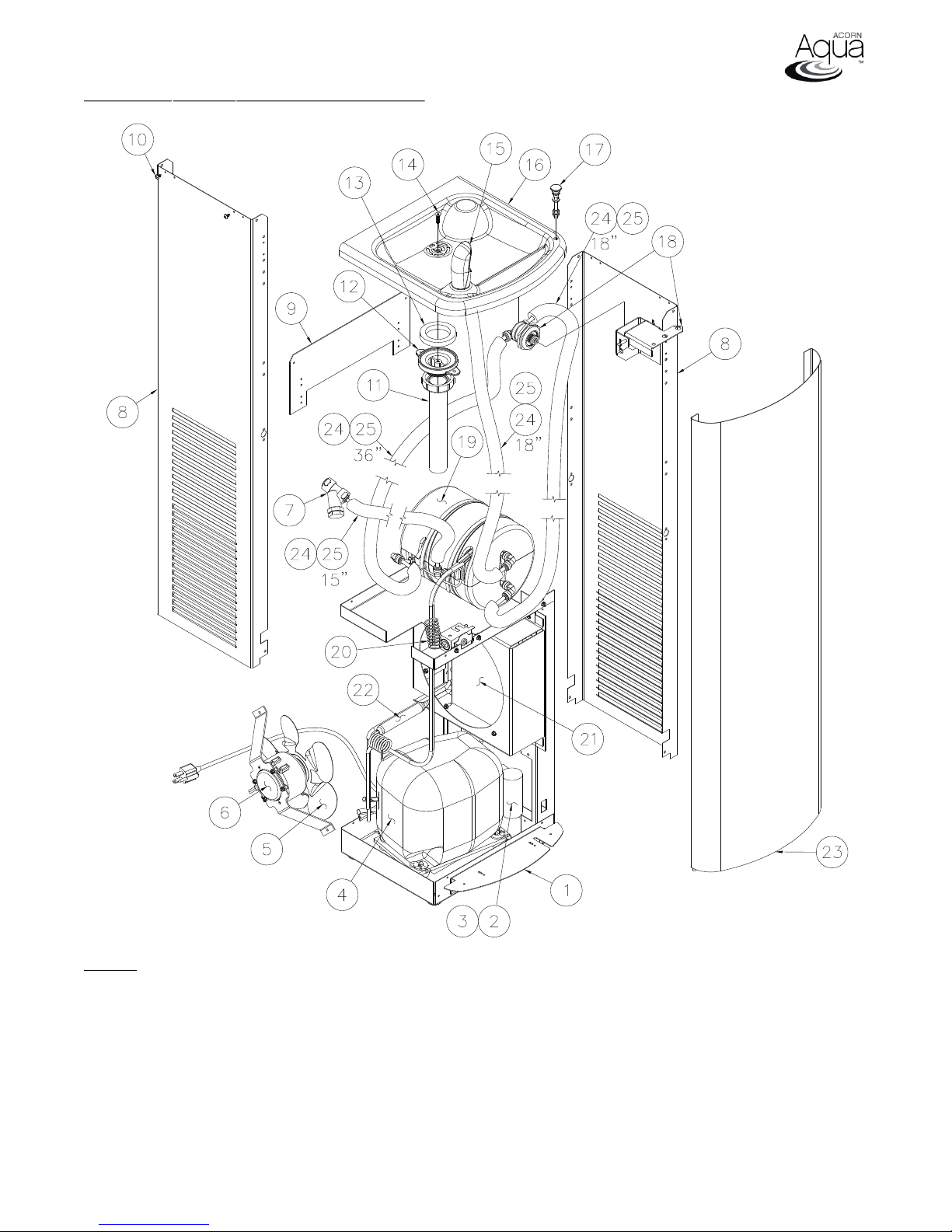
COOLER PARTS BREAKDOWN DRAWING
NOTE: See next page for table of part numbers corresponding to drawing above.
L1001054 Revised: 07/27/10
Page 7 of 8
Page 8
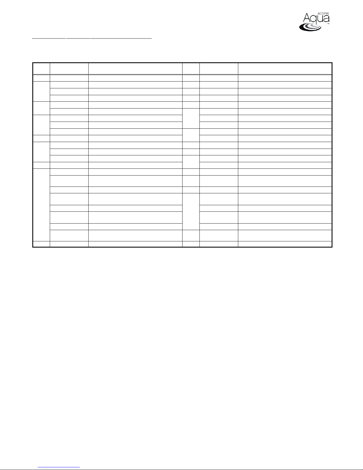
COOLER PARTS BREAKDOWN TABLE
NOTE: See previous page for fixture drawing corresponding to table of part numbers below.
ITEM
#
1 7004-015-199 Front Panel Kick Plate 10 0124-051-000 Allen Pan Head Screw
2
3
4
5 7003-350-000
6
7 7000-022-000 "Y" Strainer
8
9 7004-024-199 Back Plate 25 7012-055-000 Foam Pipe Insulation 3/8” I.D x1/4”thk
Repairs must be made with Acorn Aqua parts only. Please order through your local representative or
distributor. The phone number to locate your local representative is 1.800.591.9360.
PART
NUMBER
7012-015-000 Start Relay – 3 & 5 GPH 11 7000-039-001 Drain Tube Assembly
7012-018-000 Start Relay – 10 GPH 12 7000-005-199 Drain Adapter
7012-031-000 Start Relay – 5 GPH – 220V 13 7000-006-000 Flat Drain Adapter Gasket
7012-003-000 Start Capacitor 14 0152-040-000 Allen Flat Head Screw
7012-032-000 Start Capacitor – 5 GPH – 220V 7000-410-002 Standard Gray Flexible Bubbler Assembly
7012-014-001 Compressor – 3 & 5 GPH 7000-002-001 "B" Option Brass Bubbler Assembly
7012-017-001 Compressor – 10 GPH
7012-030-001 Compressor – 5 GPH – 220V 7004-063-199 Cooler Basin Top
7003-302-000 Fan Motor - 3 & 5 GPH 17 7004-607-001 Push Button Assembly
7012-060-000 Fan Motor – 10 GPH 18 7004-052-001 Activation Assembly
7012-062-001 Fan Motor – 5 GPH – 220V 7004-100-001 Evaporator Assembly – 3 & 5 GPH
7004-012-020 3 & 5 GPH Compact Side Panel - Granite 20 7003-250-000 Cold Control
7004-012-015
7004-012-016 3 & 5 GPH Compact Side Panel - "3" Gold 22 7012-050-000 Filter / Dryer
7004-081-199
7004-082-020 10 GPH Compact Side Panel - Granite 7004-011-015 Compact Front Panel - "2" Dark Bronze
7004-082-015
7004-082-016 10 GPH Compact Side Panel - "3" Gold
7004-083-199
DESCRIPTION
Fan Blade
3 & 5 GPH Compact Side Panel - "2" Dark
Bronze
3 & 5 GPH Compact Side Panel - "4"
Stainless Steel
10 GPH Compact Side Panel - "2" Dark
Bronze
10 GPH Compact Side Panel - "4"
Stainless Steel
ITEM
#
15
16
19
21 7003-201-000 Condenser
23
24 2169-000-000 ¼” O.D. LLDPE Tubing, Blue
PART
NUMBER
7000-000-001 "P" Option Push Button Bubbler Assembly
7004-060-199 "P" Option Cooler Basin Top
7004-102-001 Evaporator Assembly – 10 GPH
7004-011-020 Compact Front Panel - Granite
7004-011-016 Compact Front Panel - "3" Gold
7004-080-001 Compact Front Panel - "4" Stainless Steel
DESCRIPTION
L1001054 Revised: 07/27/10
Page 8 of 8
 Loading...