

Acom EKIN 2-1082 Service Manual
www.DataSheet4U.com
E-Series I/Q Modulator
1070 — 1095 MHz
EKIN2-1082
V1
Features
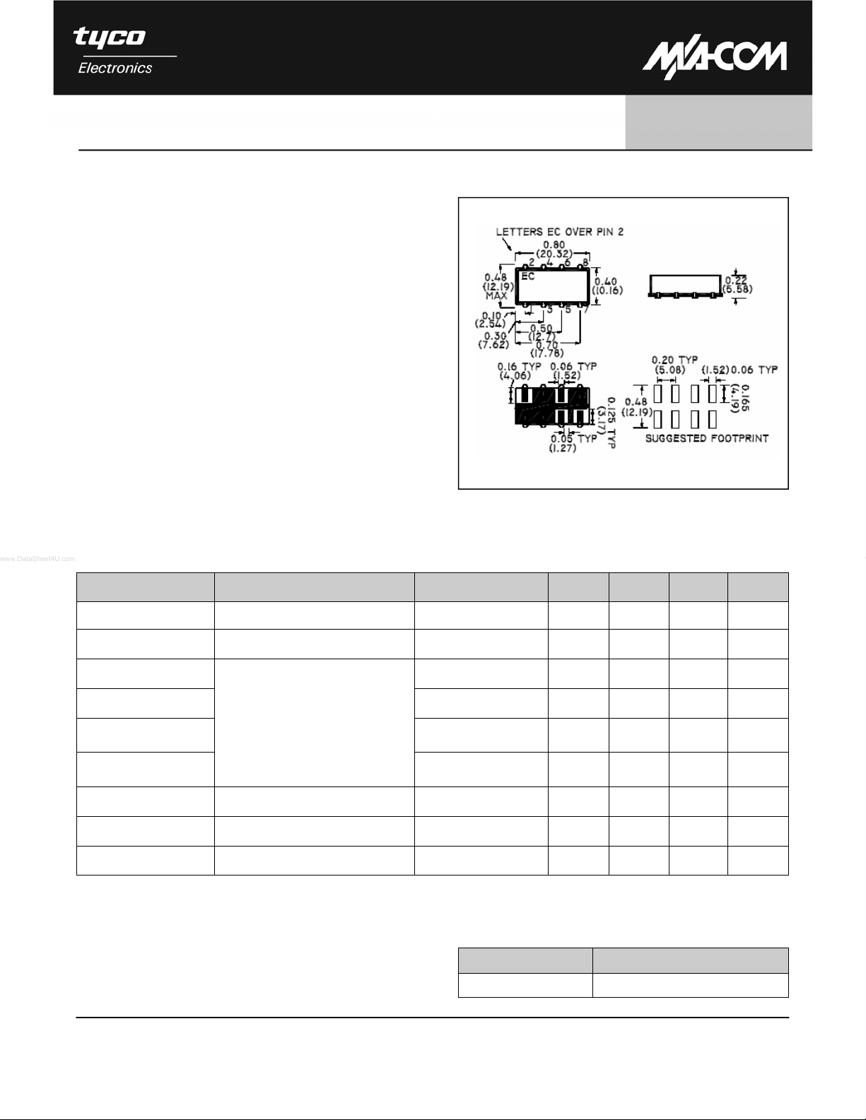
SM - 28 Package
• High Carrier Suppression
• High 3 I and 5 I Suppression
• LO Power + 10 dBm Typical
• Surface Mount
• Tape and reel packaging available
Description
M/A-COM’s EKIN2-1082 is a passive, high performance surface mount Modulator. It is ideally suited for
Direct Modulation in Cellular Base Stations. .Parts
are packaged in tape & reel.
Electrical Specifications: TA = 25°C, Z0 = 50Ω
Parameter Test Conditions Frequency Units Min Typ Max
LO Frequency — 1070 - 1095 MHz — — —
I/Q Frequency — DC - 5 MHz — — —
LO Carrier Suppression
SSB Rejection 1070 - 1095 dBc 30 35 —
Harmonic Suppression
3 x I/Q
Harmonic Suppression
5 x I/Q
Conversion Loss — 1070 - 1095 dB — 9.7 11.5
(LO) Carrier Power — 1070 - 1095 dBm — +10 ± 1 —
I/Q Drive Level — 1070 - 1095 dBm — -5 —
1
M/A-COM Inc. and its affiliates reserve the right to make changes to the
product(s) or information contained herein without notice. M/A-COM makes
no warranty, representation or guarantee regarding the suitability of its
products for any particular purpose, nor does M/A-COM assume any liability
whatsoever arising out of the use or application of any product(s) or
information.
When Q = +90 degrees relative to I;
Lower sideband is suppressed. Re-
lated to wanted sideband power.
1070 - 1095 dBc 30 35 —
1070 - 1095 dBc 30 36 —
1070 - 1095 dBc 40 50 —
Ordering Information
Part Number Package
EKIN2-1082TR Tape and Reel (300 piece Reel)
• North America Tel: 800.366.2266 / Fax: 978.366.2266
• Europe Tel: 44.1908.574.200 / Fax: 44.1908.574.300
• Asia/Pacific Tel: 81.44.844.8296 / Fax: 81.44.844.8298
Visit www.macom.com for additional data shee ts and produ ct inform ation.
E-Series I/Q Modulator
EKIN2-1082
1070 — 1095 MHz
Electrical Specifications: TA = 25°C, Z0 = 50Ω
Parameter Test Conditions Frequency Units Min Typ Max
Sideband Spurious — 1025 - 1070 dBc 25 — —
Sideband Spurious — 1095 - 1135 dBc 25 — —
Carrier Rejection — 1025 - 1070 dBc 25 — —
Carrier Rejection — 1095 - 1135 dBc 25 — —
V1
Absolute Maximum Ratings 1
Parameter Absolute Maximum
Impedance 50 Ohms Nominal
Operating Temperature -40°C to +85°C
Storage Temperature -55°C to +125°C
Pin Temperature (10 seconds) 260°C
1. Operation of this device above any one of these parameters
may cause permanent damage.
Pin Configuration
Pin No. Function
1 LO
2 Case Ground
3 Case Ground
4 Case Ground
5 I
6 Q
7 Case Ground
8 RF
2
M/A-COM Inc. and its affiliates reserve the right to make changes to the
product(s) or information contained herein without notice. M/A-COM makes
no warranty, representation or guarantee regarding the suitability of its
products for any particular purpose, nor does M/A-COM assume any liability
whatsoever arising out of the use or application of any product(s) or
information.
• North America Tel: 800.366.2266 / Fax: 978.366.2266
• Europe Tel: 44.1908.574.200 / Fax: 44.1908.574.300
• Asia/Pacific Tel: 81.44.844.8296 / Fax: 81.44.844.8298
Visit www.macom.com for additional data shee ts and produ ct inform ation.
 Loading...