

Page 1
AUTOMATIC
ANTENNA TUNNING UNIT
AUTOMATIC
ANTENNA
TUNNING UNIT
OPERATING MANUALOPERATING MANUAL
Page 2

ACOM 03AT
AUTOMATIC HF ANTENNA TUNING UNIT
OPERATING MANUAL
Table of contents
1. GENERAL INFORMATION.....................................................................................................................................2
1.1.
INTRODUCTION AND DESCRIPTION ...........................................................................................................................2
1-2.
OWNER ASSISTANCE ..............................................................................................................................................2
1-3.
EQUIPMENT SUPPLIED AND OPTIONS.......................................................................................................................2
1-4.
FEATURES..............................................................................................................................................................2
1-5.
SAFETY CONSIDERATIONS, EXPLICIT DEFINITIONS ...................................................................................................3
PRECAUTIONS:.............................................................................................................................................................3
2. INSTALLATION..........................................................................................................................................................4
2-1.
UNPACKING AND INITIAL INSPECTION.......................................................................................................................4
2-2.
LINE VOLTAGE .......................................................................................................................................................4
2-3.
REMOTE UNIT INSTALLATION ..................................................................................................................................4
3. POWER ON, RCU CONTROLS AND MENU .......................................................................................................11
4. OPERATION..........................................................................................................................................................12
4-1.
FUNCTION OPERATE AND AUTO TUNE PROCEDURE..........................................................................................12
4-2.
USING THE MEMORY .............................................................................................................................................14
4-3.
FUNCTION BYPASS.............................................................................................................................................15
4-4.
FUNCTION STATUS.............................................................................................................................................16
4-5.
FUNCTION SWR-CHK..........................................................................................................................................17
4-6.
USING STATUS AND SWR-CHK FUNCTIONS FOR RF PATH DIAGNOSTICS ............................................................17
5. MAINTENANCE ....................................................................................................................................................18
5-1.
CLEANING.........................................................................................................................................................18
5-2.
FUSES REPLACEMENT ...................................................................................................................................18
5-3.
ACOM 03AT MATCHING CIRCUIT SCHEMATIC DIAGRAM .......................................................................................20
5-4.
TROUBLESHOOTING..............................................................................................................................................23
6. SPECIFICATIONS.................................................................................................................................................24
6-1.
PARAMETERS ..................................................................................................................................................24
6-2.
FUNCTIONS.......................................................................................................................................................25
6-3.
STORAGE AND SHIPMENT..............................................................................................................................26
Page 3

2
1. GENERAL INFORMATION
1.1 Introduction and Description
This manual explains the installation, operation and maintenance of the ACOM 03AT Automatic HF Antenna Tuning
Unit.
The Automatic HF Antenna Tuning Unit (AATU) model ACOM 03AT is a complete and self-contained unit for
automatic matching of HF symmetrical-antenna impedance to an unbalanced 50Ω output, that covers a continuous
1.8 to 16MHz frequency range and will withstand 200 to 2500W input power depending on the antenna SWR used.
Input power up to 1000W is permissible in the whole frequency range when antenna SWR is 10:1 or better. For SWR
up to 50:1, matching is still possible but the frequency range and input power are restricted. AATU features a
Remote Control Unit (RCU) and can be controlled via an optical link, up to 50m long.
All indicators and controls are available via the RCU. All command input to the RCU is menu-driven.
1-2. Owner Assistance
If assistance is needed, you should contact your local dealer first. If you still have an issue you need to discuss with
one of ACOM’s specialists. The contact information is as follows: phone (+359 2) 920 96 55, fax (+359 2) 920 96 56,
e-mail acom@mail.orbitel.bg
or by mail: Bul. Nikola Mushanov 151, 1330 Sofia, Bulgaria.
1-3. Equipment Supplied and Options
The ACOM 03AT AATU is shipped in a single cardboard carton. It contains three internal cartons:
- one internal carton, containing the remote AATU unit, the RCU, and installation accessories;
- a second internal carton containing the power supply cable, and
- a third internal carton with the optical control cable.
NOTE
A coaxial cable to the station is not included. It is normally a part of the antenna set.
Use type RG213 or equivalent.
Options:
- Unbalanced output with 50
Ω UHF(SO239A) connector;
- Serial control port for the ACOM2000A HF Linear Amplifier and for ACOM2000S Automatic Antenna Selector;
- PC control via RS232 or RS422 serial port.
1-4. Features
• Easy to operate. The only operator’s obligation is to apply CW power, while the matching process is fully
automatic.
• Nonvolatile memory for 99 different user’s tuning settings and selection of the power-on default.
• LCD comment display. All AATU status indications are explained via detailed text displayed on the dot-matrix,
back-lighted liquid crystal display (LCD) on the RCU.
• Less interference and improved electromagnetic compatibility during tuning. Retuning can be achieved in 8s (2-
3s typical) and at reduced RF power (10-100W).
• Guards your transmitter during the tuning process against excessive impedance mismatch via inserting a
powerful attenuator at the input, and removing it after that.
• The RF power is disabled during each commutation in order to save the vacuum RF-relay contacts, as well as to
keep the emitted spectrum as narrow as possible during the tuning process.
• Improves harmonic emission suppression of your transmitter since the matching circuit represents a low-pass
Pi-filter.
• Saves space on the operating desk. Since the AATU is controlled by the RCU only, the remote unit can be
located up to 50m from the operation position.
Page 4

3
• Remote matching – less losses in the feed line. The design of the main (remote) unit is foreseen for outdoor-
installation requirements. This permits you to locate it closely to the antenna feed-points, thus considerably
reducing the mismatched RF path length.
• Operates automatically without special signals from the transceiver – 10 to 100W CW is the only requirement to
perform automatic matching.
• Optical control link between RCU and remote AATU unit. This avoids erratic control in strong electromagnetic
fields, which is a typical case in the near field of HF antennas emitting 1-2kW.
• Continuous monitoring of the antenna voltage, temperature and power supply in the remote unit, and indication
on the RCU of any abnormal condition.
• Resource-estimate function (STATUS) giving the percentage of inductors and capacitors involved achieving a
match. This offers a possibility for monitoring the condition of the RF path, thus to forewarn possible problems.
• Safe power supply voltage for the remote unit (24VAC provided by the RCU).
• Features BYPASS function, where the effect of the inductors and capacitors on the impedance is excluded for
broadband operation (the balun transformer however still used) – you can use the antenna without a retune,
provided the antenna is broadband.
• When AATU is powered off, the BYPASS function is performed by default, too – you can use your antenna
without an AATU when the antenna features an acceptable SWR for any frequency segment.
• RF-path condition to the AATU can be checked using the functions “STATUS”, “BYPASS”, and “SWR-CHK” –
you can timely know about possible problems.
• Protection against atmospheric electricity via sphere spark gaps and a bleeder choke.
• Options: Unbalanced output with 50
Ω UHF (SO239A) connector; Control for the ACOM2000A HF Linear
Amplifier and for ACOM2000S Automatic Antenna Selector; PC control via RS232 or RS422 serial port;
Nonvolatile memory for user tunings.
1-5. Safety Considerations, Explicit Definitions
The ACOM 03AT Automatic HF Antenna Tuning Unit is a Safety Class I unit, i.e. the third grounding lead of its mains
cord, and the grounding studs on both units (the RCU and the remote unit), marked GND (GROUND), must be
connected to the station’s grounding system for safe operation. The AATU is designed to meet international safety
standards and complies with CE safety and electromagnetic compatibility requirements, as well as FCC regulations.
This operating manual contains information, precautions, indications for cautions and warnings which must be
followed by the user to ensure safe operation and to keep the ACOM 03AT in safe operating condition.
PRECAUTIONS:
The EXPLICIT DEFINITIONS described below apply to this operating manual:
W A R N I N G notes call attention to a procedure which, if not correctly performed, could result in personal injury,
fire hazard or electric shock.
C A U T I O N notes call attention to a procedure which, if not correctly performed, could result in equipment
damage, not only in the AATU.
N O T E notes call attention to a procedure which, if not correctly performed, could result in inconvenience only.
W A R N I N G HIGH VOLTAGE!
The AATU works with mains voltage 220-240VAC 50-60Hz and high DC voltage up
to 300VDC, which are LETHAL! Also, for your safety pull the AATU power plug out
of the mains wall outlet and WAIT AT LEAST 3 minutes EACH TIME BEFORE you
remove any cover!
Page 5

4
W A R N I N G HIGH VOLTAGE!
Never allow anyone, ESPECIALLY CHILDREN, to push anything into holes in the
case – this will cause electric shock. NEVER TOUCH AN ANTENNA OR ANTENNA
INSULATORS during transmission – this may result in an electric shock or burn.
The RF voltage on the antenna insulators may exceed 5000V! NEVER EXPOSE the
RCU to rain, snow or any liquids. AVOID placing the RCU in excessively dusty
environments or in direct sunlight.
W A R N I N G
Do not undertake on your own repairs or changes in hardware or software of the
AATU in order not to endanger your or other’s health and life and not to damage the
AATU and the equipment connected with it, not covered by warranty. The
manufacturer is not liable for another’s actions and responsibility shall be assumed
by the doer.
C A U T I O N
To avoid damage (not covered under warranty) read the Installation – Section 2 of
this operating manual carefully. If you have any doubts about the installation,
operation or safeties of the AATU please consult your dealer.
2. INSTALLATION
2-1. Unpacking and Initial Inspection
C A U T I O N
Before you start any action on installing the AATU, thoroughly read this manual.
First, carefully inspect all cardboard cartons and their contents for physical damage.
If damage is noticed, notify your dealer immediately. Delay may infringe carrier’s
warranty conditions. Keep all packing for possible future transportation!
Take out the RCU, its mains power cable and the serial-control cables (option). Carefully check the RCU and the
cables for any possible shipping damage. Leave them оn the place where the RCU will be installed.
The remote (main) unit, together with the remaining installation accessories and both cartons with the 50m cables
are intended for installation at the antenna area. Take them out of their cartons separately and check carefully for
transportation injury. Return them back into their cartons after that in order to make it easy and safely to carry them
to the remote-unit installation place (for instance, at the antenna base).
2-2. Line Voltage
C A U T I O N
To avoid damage (not covered under warranty), check carefully if the voltage for
which the AATU is set corresponds to your mains nominal voltage.
Normally the AATU is supplied with Voltage Selector set for a nominal mains voltage of 230V. There might be
exceptions in cases of special delivery.
2-3. Remote Unit Installation
N O T E
Before you start any action on installing the remote unit, make a plan about how the
cables would be laid and where would they come through the wall on the premises
where the RCU will be installed. Have in mind that there is a connector installed on
the bottom end of the supply cable that needs a minimum of 22mm (7/8”) diameter
Page 6

5
hole. If you prefer a smaller hole, you should thread the whole cable length through
the wall, beginning from its bared end and leaving the connector in the room. In
such a case you would need only 8mm (5/16”) for this cable and another hole of
7mm (9/32”) diameter for the optic cable.
N O T E
The coaxial cable needed for a connection between the remote unit and the station
is not supplied but you should foresee its installation, too (unless it has been
installed previously). Normally you will need a 11mm (7/16”) diameter hole or 20mm
(25/32”) should you want to thread the cable with the PL-259 connectors installed.
W A R N I N G HIGH VOLTAGE!
To avoid disaster, the AATU installation and connection to the grounding and to the
antenna should be carried out only in serene quiet and sunny weather, when no risk
for thunders or atmospheric electricity activity exists. Not only a direct lightning hit
but also nearby strokes, as well as electricity induced by storm-clouds or a dusty
wind can cause voltages in either the antenna or the cables you are installing, that
are dangerous for life!
W A R N I N G HIGH VOLTAGE!
Do not begin installing the AATU before you have prepared a proper and safe
lightning grounding installation! Never use the AATU unless it is grounded to
guard you against lightning strokes! Do not use casual ground connections!
Installation of the remote unit must be accomplished in the order described below, before you connect the RCU and
the cables to your station.
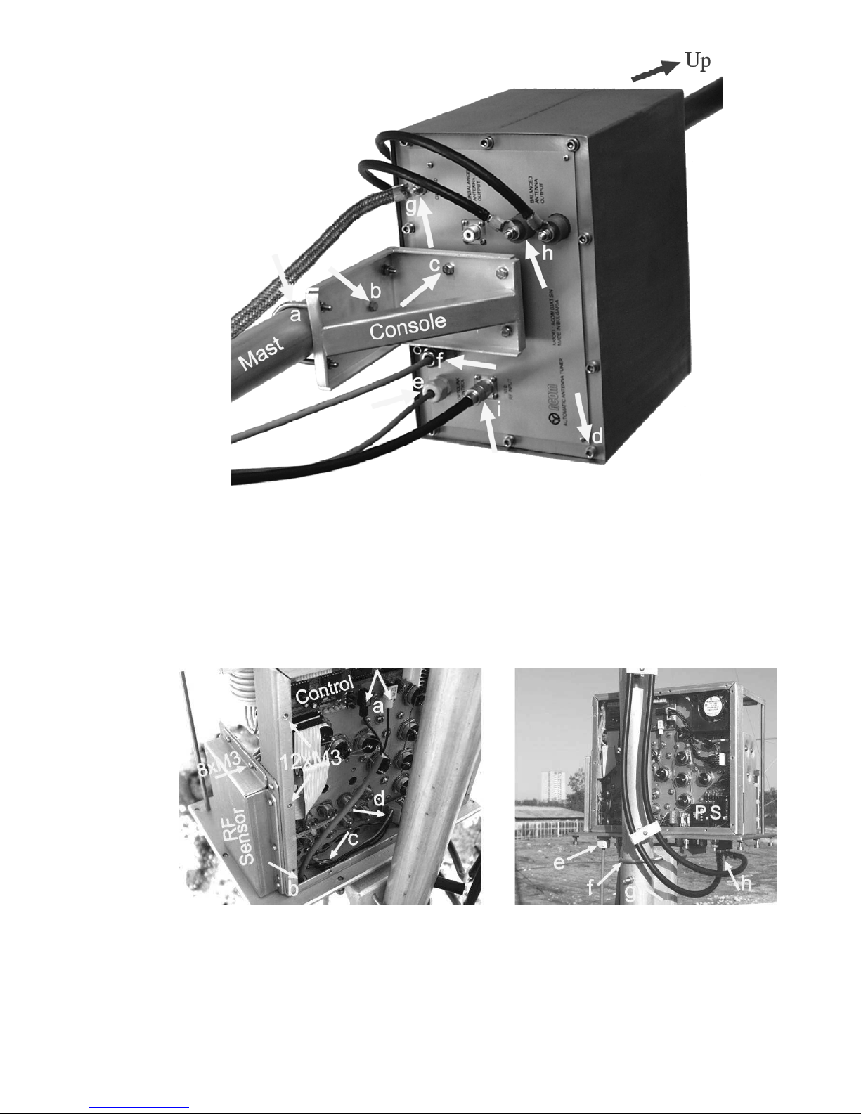
a) Mount the AATU installation console to the antenna mast at a height at least 80cm (2.6 feet). This is needed in
order that winter snow cannot reach the height of the unit. Use both U-bolts M6 and the fixing screw M6x70mm
(supplied) – see fig.2-1,a,b & 2-2,f,g. Do not miss the fixing screw that avoids turning the unit around the mast.
b) Place the remote unit on the installed console and orient it with the hood head upward and the connectors
downward (see fig.2-1 and 2-2). You may need an assistant for the next operation.
C A U T I O N
When outdoors installed, the unit must be positioned with its hood head upward,
and with the connectors and the cable glands – vertically down. Never install the
remote AATU unit inclined to the vertical for outdoors usage in order to prevent it
from precipitation-water leaking into the unit as this may lead to damage, not
covered by warranty!
Settle carefully the unit onto the console and align its four installation blind holes (M6 threaded – see fig.2-4) to the
corresponding console holes.
An assistant may be needed at this point to hold the unit steady while you screw in the four screws М6х16mm (fig.21,c) loosely. Tighten them properly using a 5mm (0,2”) Allan key.
After having finished the above mount operations please check the strength and reliability of the installation.
Page 7
6
Fig.2-1. Remote AATU unit on-mast installation and cables arrangement (bottom view).
c) Using a 5mm (0,2”) Allan key unscrew all 10 captive screws М6 located on the bottom panel of the unit (see fig.21,d). Pull the metal hood upwards carefully and remove it. Using a “Philips 1” screwdriver, unscrew all 12 М3х8mm
screws that hold the rear lid of the unit. Carefully slip it off in order to get access to the Printed Circuit Boards “Power
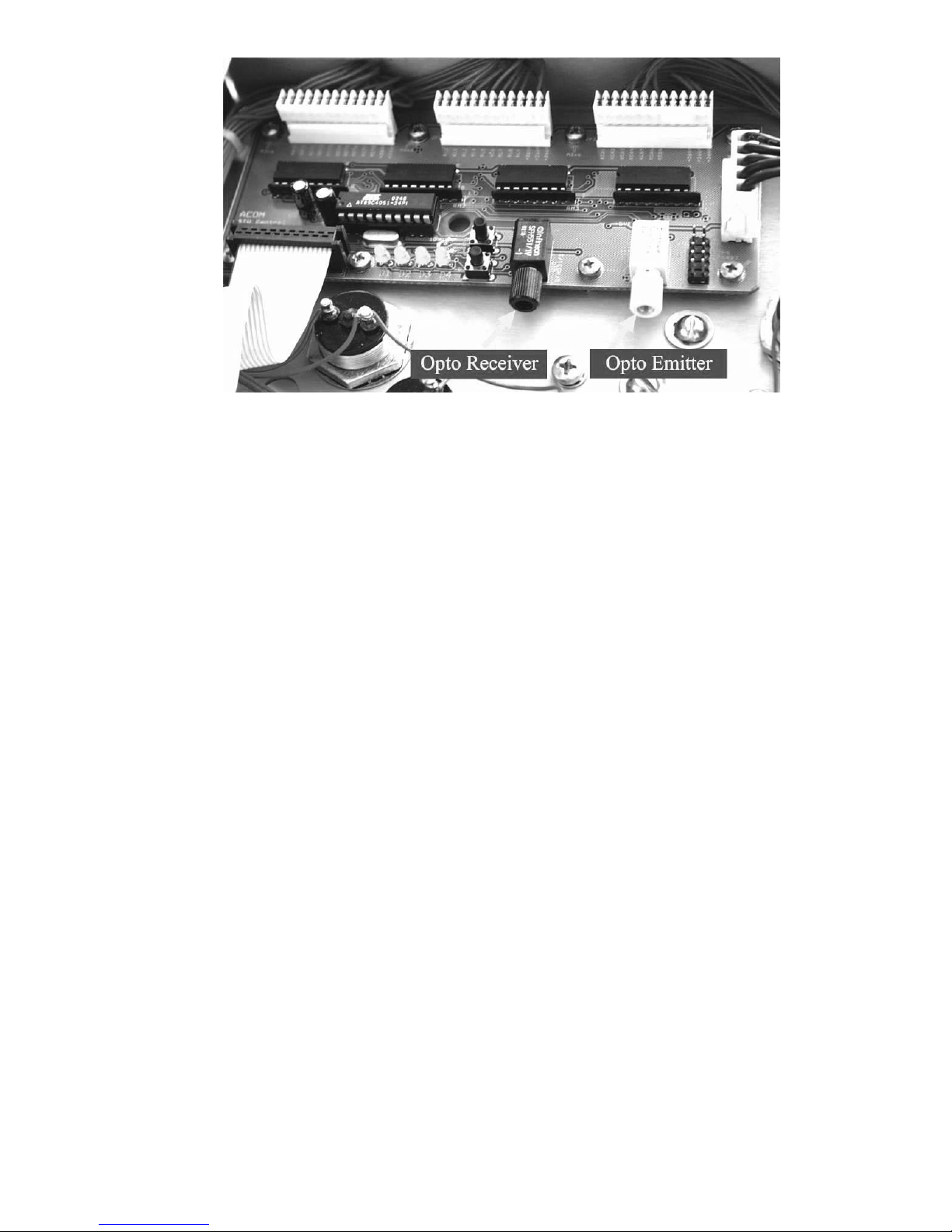
Supply” and “Control”. On the “Control” PCB find the two optic devices, marked U10 and U11 on the PCB, and
having knurled plastic nuts, permanently installed on their optic connectors (a split-socket type to tighten the opticcable cores) - see fig.2-2,a & 2-3. The black-case device is the photo detector receiver while the white-case is the
optic emitter. For now, as the other cable end is still not connected, it is meaningless which core to which device
shall be connected. Identifying is easy on the second end at the first power on see S.2-4(c).
Fig.2-2. Remote unit connections
d) Unscrew the plastic cable-gland cap (marked “OPTOLINK CONTROL” on the bottom panel - fig.2-1,e & 2-2,e) and
thread it over the optic cable in such a direction as to be able to screw it onto the same cable gland later. Push the
bared optic cable end into the cable-gland hole and direct it to both optic-device apertures (fig.2-2,a-b & 2-3).
Page 8
7
Fig.2-3 The “Control” PCB and optic devices in the remote AATU unit.
Push 2-3cm (one inch) more cable length into the cable gland (so that not to stretch the inside cable length after
having it connected to the optic devices (fig.2-2,a-b) and tighten the cable-gland cap using a wrench sized 22mm
(7/8”). Use only enough force while tightening in order that the cable be tight and could not slip out when pulled
occasionally (do not overdo it since a cable-gland destruction is likely).
C A U T I O N
The optic cable ends are supplied readily bared and prepared for installation.
Nevertheless, check on each cable end whether the external sheath has been
removed about 100mm (four inches), in order to move apart both fiber cores to both
optic devices. In addition, each fiber face must be cut as smooth as possible and in
a vertical section. Check whether the cut surface is clean of contamination and
lucid.
Should you need to bare the cable once more again, first peel off the external cable sheath about 10-12cm (four
inches) from the end. Be careful not to injure the cores under the sheath. Then cut small lengths (2-5mm, 0.1-0.2”) off
each core end in order to expose a clean and lucid surface of the transparent light-guiding plastic fiber. Use a clean,
sharp and smooth-surface knife. Keep track to make a precisely vertical section. The light loss and reflections
depend strongly on this operation quality. To improve the cut performance we recommend to pre-heat the knife blade
(to about 70-80 deg.C or 160-175F). Be careful not to contaminate the blade while heating and not to over-heat it.
Loose the split-socket-knurled nut of either optic device slightly (fig.2-3). Then push either core into the split socket,
shove the core against the stop, and tighten carefully its knurled nut by hand. Keep track that no foreign matter is
caught into the optic device aperture since this would obstruct the light beam.
Use only enough force while tightening in order that the cable be tight and could not slip out when pulled
occasionally (do not overdo in order not to damage the plastic case or the optic device). Repeat the same operation
with the second cable core and the other optic device. As mentioned above, identification of the channels transmit
and receive will be made at first power on – see S.2-4(c).
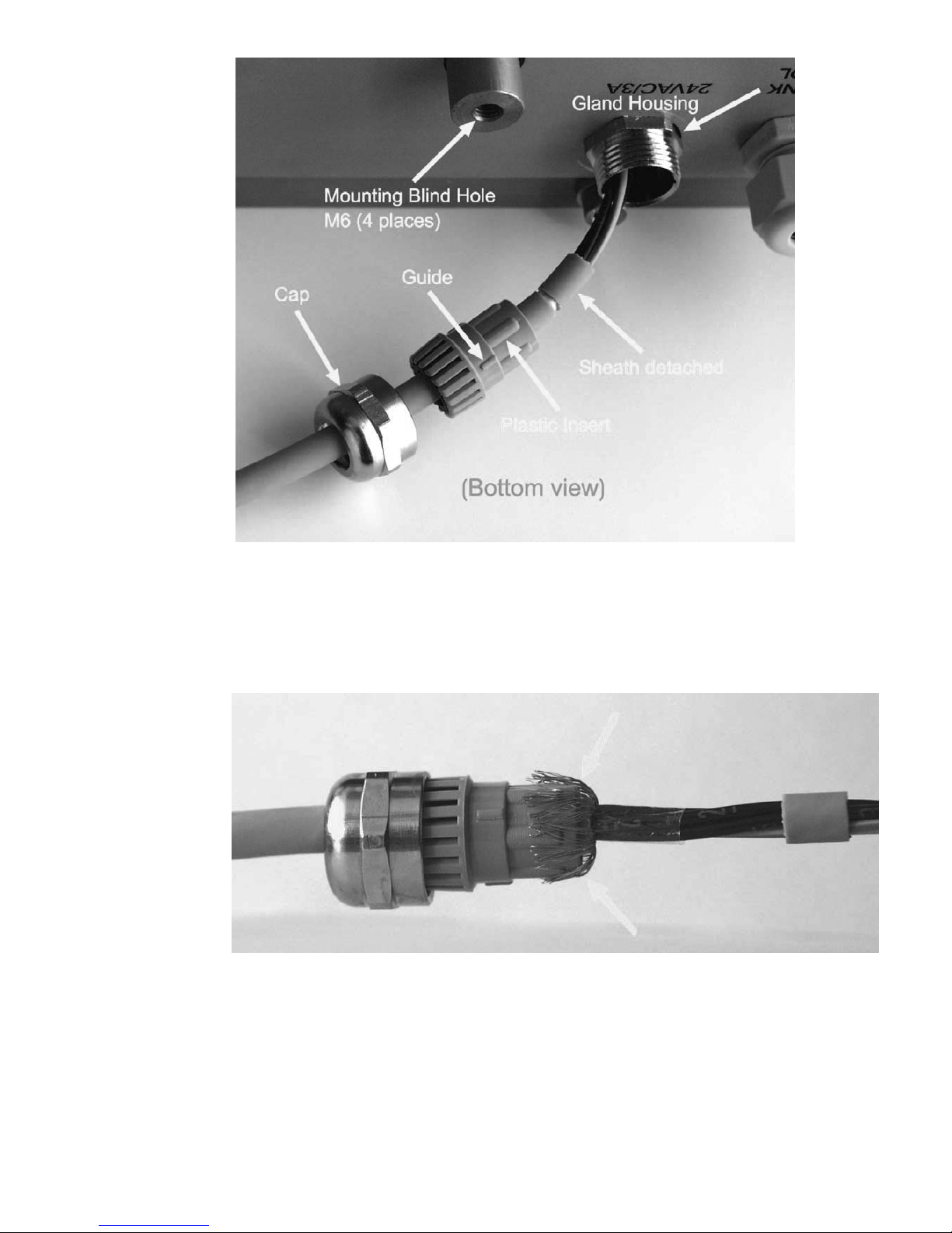
e) Unscrew the metal cable-gland cap (marked “24VAC/3A” on the bottom panel (see fig.2-1,f) and thread it over the
bared end of the four-core screened power-supply cable in such a direction as to be able to screw it onto the same
place later. Take out the plastic insert from the cable gland housing. Thread the insert over the cable end in such a
direction, that its split end be next to the metal cap, and the slender end – to the cable bared tag (see fig.2-4).
Page 9
8
Fig.2-4 Power supply cable gland of the remote unit (bottom view).
Drag the detached (10-12mm or ½”)-piece of the cable sheath towards the cable end in order to loose the shielding
braid. Remove the cloth layer from the shield and carefully spread the braiding wires below it in a radial direction.
Move the plastic insert towards the bared area until the insert face reaches the split braiding. Then bend the
shielding wires back in order to lay them over the outside surface of the plastic insert (fig.2-5). Put them in order and
arrange carefully around the insert periphery.
Fig.2-5 Screening braid shaped before to push into the cable gland.
Holding the plastic insert fixed to the cable, push all four cable cores into the gland housing and direct them towards
the “Power Supply” PCB inside (fig.2-2,c-d). Use a small rotation around the insert axis in order to align its three
guides to the corresponding grooves in the metal housing, then carefully shove the insert into the gland body,
together with the shaped cable. Now, press the insert inwards in a manner that the back-folded braid touches the
metal-housing head closely, and while holding it in this position, screw in the metal cap against stop. Finally, tighten
the cap using a wrench size 20mm (25/32”). Use only enough force while tightening in order that the cable be tight
and could not slip out when pulled occasionally (do not overdo in order not to damage the gland thread).
Page 10

9
f) Inside the remote unit, direct the cable cores to both terminal pairs located on the “Power Supply” PCB, that are
marked J1 & J2 (~24VAC) – see fig. 2-2,c-d and 2-6. The power supply is applied through each pair in parallel (each
pair is one pole of the power supply).
Fig.2-6 Power-supply PCB: cable connection and fuses in the remote unit.
Using a flat-tip screwdriver 3х0,6mm (1/8”x0.02”) loose the terminal screws. Push the bared end of core nr.1 (marked
white over the black core insulation as well as on the terminal block), into the bottom terminal, and tighten it properly.
Above it connect core nr.2, then in an up-sequence - core nr.3, and at the top connect the yellow-plus-green colored
core (to the terminal that is marked with “Y”).
g) Install the rear lid of the unit. Using a “Philips 1” screwdriver, screw in all 12 screws М3х8mm loosely. Then tighten
properly but do not push strongly along screw axes in order not to push out any captive nut from the chassis.
Slip on the protective metal hood and lower it carefully downwards until it stops onto the bottom panel of the unit.
Screw in loosely all 10 captive screws М6 (located on the bottom panel - see fig.2-1,d). Then tighten properly using a
5mm (0,2”) Allan key.
h) Connect the remote-unit grounding clamp, marked “GROUND” on the bottom panel, to the lightning-protection
grounding system (see fig.2-1,g).
i) Connect the balanced antenna feeder to the terminals marked “BALANCED ANTENNA OUTPUT” on the bottom
panel (see fig.2-1,I & 2-2,h). Shape its leads in an order not to permit accessing the AATU case or any grounded part
of the installation.
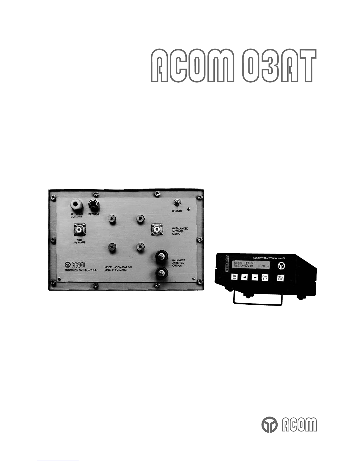
j) Connect the RF coaxial cable to the coaxial connector marked “50
Ω RF INPUT” on the bottom panel (see fig.2-1,i).
Use cable type RG-213 or equivalent.
C A U T I O N
Using the “UNBALANCED ANTENNA OUTPUT” option is only permissible after
having disconnected the internal connection between the matching circuit output
and the BALUN transformer input, in order not to destroy the balun transformer.
Contact your dealer or the factory for details.
k) Lay the cables along the route to the station premises, stabilize them and protect against damage in case of a
movement, wind, snow or ice. Lead in the cable ends through the wall (if not done previously). Get measures against
trickle water leaking through the building wall.
Page 11

10
2-4. Connections to the Station
The connections of the AATU and its RCU to the station must be accomplished in the order described below, before
you apply mains voltage to the RCU.
a) First connect the ground stud of the RCU marked “GND” to the station’s grounding system – see the left yellow
arrow at fig.2-7.
Fig.2-7 RCU rear panel, grounding terminal, and mains fuse.
b) Connect the remote-unit power supply cable to the 5-contact round connector on the rear panel, marked
“24VAC/3A OUT”.
c) Connect the mains power cord to the 3-spade IEC mains socket, marked “230V 50/60Hz”. The optic cable is still
not connected.
W A R N I N G HIGH VOLTAGE!
Do not use non-standard mains power cords! If the power plug supplied is different
from the standard in your country, the power plug must be replaced by a qualified
electrician who must check whether the third grounding lead of the mains cord is
properly connected.
C A U T I O N
To avoid damage (not covered under warranty), check carefully if the voltage for
which the AATU is set corresponds to your mains nominal voltage (see S.2-2).
After following all instructions in S 2-3 & 2-4(a,b,c), make sure that the main switch POWER located on the rear
panel is in OFF position (so that the red stripe on the switch is hidden) and then connect the power plug of the RCU
to the wall mains outlet prepared for it.
Before you switch ON the POWER switch, take the optic cable tag and look carefully which one out of the two cable
cores would glow with red pulsing light immediately after a turn ON. Now turn ON - in either core of the cable shall
appear the mentioned red light. It will blink four times (about 0,5s each), and will stop after that. Note the blinking
cable core and switch OFF. Mark this core using a sticking label or use another convenient method to recognize it –
this is the cord incoming from remote-unit transmitter and it should be connected to the optic receiver device located
on the “RCU control” PCB (see S.2-4,d).
Now disconnect the power plug from wall mains outlet.
Page 12

11
d) Connecting the optic cable to the RCU.
W A R N I N G HIGH VOLTAGE!
The AATU works with mains voltage 220-240VAC 50-60Hz and high DC voltage up
to 300VDC, which are LETHAL! Also, for your safety pull the AATU power plug out
of the mains wall outlet and WAIT AT LEAST 3 minutes EACH TIME BEFORE you
remove any cover!
After pulling the power plug out of the mains wall outlet, using a “Philips 2” screwdriver unscrew all four side screws
from the top cover of the RCU. You will see the PCB “RCU Control” installed horizontally and having two optic
devices U3 and U4 of the same type like those you have seen yet in the remote unit (see fig.2-3). The operations on
the optic cable connection at the RCU side are analogous to those from S.2-3(d).
Unscrew the spiral cap of the plastic cable gland marked “OPTOLINK” (see fig.2-7) and thread it onto the cable
oriented with its thread towards the cable end. Push the cable into the RCU case through the cable gland and give it
some margin in order that the cable cores freely access the optic devices without straining. Now screw in the spiral
gland cap and tighten it using a wrench 15mm (19/32”). Use only enough force while tightening in order that the
cable be tight and could not slip out when pulled occasionally (do not overdo in order not to damage the plastic gland
thread).
Loose slightly the split-socket-knurled nut of the optic receiver device U3 (black housing). Then push the marked
core (S.2-4,c) that comes from the remote-unit transmitter, into the split socket. Use tweezers on need. Shove the
core against the stop, and tighten carefully its knurled nut by hand. Keep track that no foreign matter is caught into
the optic device aperture since this would obstruct the light beam.
Use only enough force while tightening in order that the cable be tight and could not slip out when pulled
occasionally (do not overdo in order not to damage the plastic case or the optic device).
Repeat the same operation with the non-marked cable core and the other optic device U4 (white plastic case).
Now install the top cover. Screw in loosely all four side screws, then make even the cover, and tighten the screws
using a “Philips 2” screwdriver. Do not push strongly along screw axes in order not to push out any captive nut from
the chassis.
e) Connect the RF coaxial cable that comes from the remote unit (with a PL-259 connector) to the transceiver output
(or the amplifier or antenna selector when available).
f) If you have options supplied, connect also their cables (KEY-IN and KEY-OUT, serial control channels COM1,
COM2 or RS422). The amplifier ACOM2000A connects via a “Null Modem” cable to the 9-contact connector COM2.
In this way, the AATU will send a “go to STBY” command to the ACOM2000A each time when you press the TUNE
button on the RCU. If the cable is not installed you should set the amplifier in STBY manually.
3. POWER ON, RCU CONTROLS AND MENU
C A U T I O N
To avoid damage (not covered under warranty), check carefully if the voltage for
which the AATU is set corresponds to your mains nominal voltage (see S.2-2).
After following all instructions in S 2, you can turn ON the Main power switch on the rear panel. The LCD back-light
and all five buttons must light (see fig. 3-1) and on the upper LCD row should appear the following message:
Connecting…
The self-test is accomplished in about 2s and then the AATU retrieves the power-on default setting – this will be
explained later in S.4-2. Now it is best to get acquainted with the menu control. Press the Esc button twice to reach
the main menu:
Page 13

12
Fig.3-1 ACOM 03AT Remote Control Unit (RCU).
BYPASS [OPERATE]
STATUS SWR-CHK
On the menu are shown the four main functions that are available – BYPASS, OPERATE, STATUS, and SWR-CHK
(SWR check).
The function OPERATE is shown selected between square brackets in the example above. If you wish to select
another function, move the brackets in the required direction with the < (left) and > (right) arrow buttons, so that they
enclose the desired item. The selected function would be activated if you press the button Enter. When the edge of
the display is reached, future movement in the same direction will cause the brackets to scroll to the opposite row of
the display. After that, you can move the brackets to the left or to the right using the corresponding arrow button.
For instance, press the button < (left) to select the function BYPASS:
[BYPASS] OPERATE
STATUS SWR-CHK
To exit from an item, press the Esc (Escape) button. If you press it repeatedly, you will escape from any menu level
and you will eventually reach the main menu. When that menu is reached, the ESC button becomes inoperative and
you have to select a function.
The purpose and use of these four functions is described in Section 4. To power off the AATU just switch the main
switch POWER located on the RCU rear panel in OFF position (so that the red stripe on the switch is hidden).
4. OPERATION
Operation of the AATU is simplified a great deal due to the high degree of automation and intuitive control. You can
start operation immediately after it is installed. However, to make full use of its possibilities and to fully configure to
your local conditions, we recommend you thoroughly read the following information.
4-1. Function OPERATE and AUTO TUNE procedure
This is the main function of the AATU. When you select it from the menu, you will see the function inscription:
Mode: OPERATE
-----_-----
Page 14

13
The bottom row of the LCD is intended to indicate the frequency segment where the AATU is tuned. Now you have
to set the needed frequency on the transceiver and to select the needed antenna where the AATU will be tuned.
C A U T I O N
Before giving a tuning command, you have to stop any transmission and put the
amplifier (when available) to bypass (STBY mode). Never apply more than 100W
tuning power in order not to trip either AATU protection!
C A U T I O N
If you use more than one antenna you have to select the proper antenna
corresponding to the needed frequency and/or desired direction.
a) AUTO TUNE procedure.
When the antenna is selected and with no RF applied to the AATU, you can start the auto-tune procedure pressing
the button AUTO TUNE on the RCU:
Mode: AUTO TUNE .
Apply 10-100W RF ( )
The AATU will then wait for you to apply between 10 and 100W continuous carrier (CW) signal with the desired
frequency. If you leave the AATU waiting longer than 20s, then it will inform you:
Mode: AUTO TUNE
Timeout Expired
When you apply a tuning signal as needed, an asterisk will appear between two brackets at the right-low corner on
the LCD. It will indicate the presence of a proper tuning signal:
Mode: AUTO TUNE .
Apply 10-100W RF ( * )
The process of automatically matching the antenna impedance begins when the power remains constant within the
needed boundaries. After about one second, tuning begins and the indication changes:
Mode: AUTO TUNE .
In Progress … ( * )
This way, the AATU reports that the essential matching process (via impedance measurements and assessment,
and switching the relays) has been initiated in the remote unit. This takes various periods depending on the
frequency and the antenna impedance for this frequency but never in excess of 8s (typically 2s). After the procedure
has finished, the AATU will call to stop tuning power (for at least one second before starting transmission with a
tuned AATU):
Mode: AUTO TUNE .
Stop RF … .
At last, after you stop the tuning power, you will be informed about the results:
Mode: OPERATE .
06970-07110 * OK *
b) Indication.
The frequency segment where the AATU is currently tuned is shown on the bottom line (кHz). It spans about ± 1%
around the tuning frequency that you have applied. Normally you can use this frequency segment with excellent
results without a retune of the AATU.
To the right of the frequency-segment indication, you will see the procedure result as described below.
If for some reason matching cannot be accomplished successfully, the process ends up with a “SWR>1.5” or
“Unstable RF Power” indication instead of the usual * OK *. This is a rare case caused for example by excessive
antenna SWR or unstable tuning power).
Page 15

14
When the SWR is above 1.5:1, the AATU stops at the best SWR achieved, so you could check whether it would be
acceptable for your transceiver as a last resort (usually if below 2:1). We recommend, however, to make a correction
or repair the antenna when needed, in order to improve its SWR.
Although the AATU is capable to match a much wider than the guaranteed impedance range, it is advisable that the
antenna SWR be included in the range where the AATU matching capability is specified (see S.6-1,e).
C A U T I O N
If you give an AUTO TUNE command while RF is presently applied, you will see a
“Stop RF …” message and the operation will be rejected. Just stop transmitting,
place the amplifier to bypass (STBY), and repeat the command.
C A U T I O N
If you occasionally interrupt the tuning power while the AUTO TUNE process is
being executed, you will see a message “Unstable RF Power”. Just repeat the
command.
N O T E
You can start the AUTO TUNE procedure directly from the main menu, as well as
when either OPERATE, STATUS, or SWR-CHK function is active. You cannot start
AUTO TUNE from BYPASS function. You will note that the AUTO TUNE button
becomes dark while it is inoperative.
If you press the button Enter for the second time while in OPERATE, you will start the Memory sub-function which is
explained in the next section. To exit, press the button Esc repeatedly until the main menu appears.
4-2. Using the Memory
This is a sub-function of the function OPERATE. To select it, while in OPERATE press the button Enter – you will
see the function inscription:
Mode: Memory *12d
6970-7110 .
a) Indication.
To the right on the upper line is shown the current memory-cell number. The characters in front and behind the
number can be missing as explained below.
If the memory cell appears marked with an asterisk * in front of the number, this means that the cell contents is in
effect and it is identical with the tuning (relay settings) in the remote unit. If the asterisk is not present there, you are
only looking at the cell contents (frequency segment), however it is not active. This means that the current relay
status of the remote unit is different from what is written in the memory for that frequency segment.
If the letter “d” is shown behind the cell number, this means that this memory cell has been selected by the operator
to be used as default setting at a power on. The selection method is described below.
The bottom row is intended to indicate the frequency segment the tuning has been written about in the memory cell
shown. If no numbers are present on this line but only a “---------“ appears, the current cell has been still not used.
b) Buttons operation.
The following commands are available for memory operation:
- using the buttons < or > you can decrease or increase the memory-cell number. You can look up the list of the
frequency segments stored with a tuning in various memory-cells (or only the part of interest). The remote-unit
relay status is not being changed while you are listing the memory unless you activate either cell contents.
- If you press and hold the button Ent, you will get access to the three commands that you can use concerning the
currently displayed memory cell. The following screen will prompt you to give a command:
Mode: Memory *12d
DEF RCL STO .
Command abbreviations appear at the top of the three buttons from the left, namely:
Page 16

15
DEF (Default) – above the button Esc – if you press it together with the Ent and release both buttons after that, the
letter “d” will appear to the right of the memory-cell number. This mark denotes a default cell that will be used by
default at a power on.
C A U T I O N
Before giving a RCL command, you have to stop any transmission.
RCL (Recall) – above the button < – if you press it together with the Ent and release both buttons after that, the
contents of the current memory cell will be sent to the remote unit and it will become an active cell. Respectively, an
asterisk will appear to the left of the cell number.
STO (Store) – above the button < – if you press it together with the Ent and release both buttons after that, the
current relay settings and the tuning frequency of the remote unit will be memorized in the currently displayed
memory cell. Respectively, an asterisk will appear to the left of the cell number (the cell content is equalized with the
remote unit status i.e. it has become active). In addition, on the bottom row appears the new frequency segment for
which the stored tuning will be valid.
You will see that after a command has been given, its inscription disappears from the screen – this will be a notice
that the command has been accepted and done. You can give an arbitrary commands queue while you are holding
the button Ent, as well as you can release it for each command.
c) Using the memory.
You can prepare AATU tunings for the frequencies that you use frequently and store them in different memory cells
(with numbers 1 to 99) using the command Ent+STO (Store). The button AUTO TUNE is active also while using the
memory and is to be used in the same manner as it was in the OPERATE function (see S.4-1). The button is not
accessible only when a command selection is being expected (DEF, RCL or STO combined with Ent).
Once you have memorized the tunings for all the frequencies of interest, you can retrieve them in an arbitrary order
from the memory using the command Ent+RCL (Recall), i.e. to get them active. The tunings do not disappear even
after you switch off the power supply, i.e. the tunings memory is nonvolatile.
After you have activated a memory tuning via an Ent+RCL (Recall) command, you may write its content in another
memory cell using the command Ent+STO (Store)
. You will be able to rearrange the memory cells via “relocating”
them in new cells (without a retune) and then using the “vacated” cells to store new tunings there.
N O T E
Using too old tunings can exhibit high SWR (if the conditions at the antenna have
changed significantly since the day the tunings have been stored). Should this
happen, we recommend that you refresh these tunings using the AUTO TUNE
procedure and then store new tunings via the Ent+STO (Store) command.
Once a memory cell gets activate, you can abandon the Memory sub-function temporarily by pressing the button Esc
until you reach the main menu. Then, the remote unit tuning is not being changed since the current tuning status is
being considered being operative. In this situation, you can use either function BYPASS, STATUS or SWR-CHK (for
instance checking the ATU resource in use or the present SWR of an old tuning). If you have not made any AUTO
TUNE meanwhile, at returning to the Memory sub-function you will have the same tuning status as it has been before
you left it (even if you have used the BYPASS function).
Should you need changing the default power-on memory cell, select the new cell via the buttons < or > and then use
the Ent+DEF (Default) command. You can do this at any time while using the Memory sub-function, as well as
immediately before switching the power off.
4-3. Function BYPASS
C A U T I O N
Before giving a BYPASS command, you have to stop any transmission.
When you select the function BYPASS between the square brackets in the main menu and then press Enter, you
will see the function inscription:
Mode: BYPASS
Page 17

16
BROAD BAND
At a function selection all relays are switched off, thus the effect of the inductors and the capacitors on the remoteunit impedance transformation is eliminated. While the BYPASS function is active, the AUTO TUNE function is not
accessible (the button is dark).
This way, you can operate without re-tuning the AATU provided the antenna SWR is acceptable in a certain
frequency range.
C A U T I O N
Using a coaxial feeder at SWR above 3:1 is not recommended in the HF range.
When the SWR is higher than 3:1 and you want to use this antenna at high RF
power, you risk damaging the coaxial cable between the station and the antenna.
The cause is increased current and voltage along the cable, as well as a large
amount of heat they generate in the cable wires and insulation. We recommend you
use AUTO TUNE in either OPERATE, STATUS, or SWR-CHK function in such
conditions in order to use your cable safely as well as to increase the radiated
power.
Besides operating, you may use this mode also for preventive checks of your antenna and feeder system. While in
BYPASS, check the antenna SWR for several representative frequencies and compare with data copied providently
while you have been confident the system was intact.
The function can be restarted via the button Enter. To exit, press the button Esc until the main menu appears.
4-4. Function STATUS
When you select the function STATUS between the square brackets in the main menu and then press Enter, you will
see the function inscription:
CT=3E L=012 CA=00 CS
24% 3% 0% N
Various figures may appear in the example above. On the upper LCD line is shown the current position of the main
RF-tuning blocks. They are configured in a standard low-pass Pi-circuit to perform the impedance matching in the
remote unit. See fig.5-1 and S.5-3 for details. The following symbols are used:
CT – comprises a group of 8 capacitors connected in parallel to the transmitter input;
L – comprises a group of nine inductors connected in series between the transmitter input and the antenna output;
CA – comprises a group of six capacitors connected in parallel to the antenna output;
CS – a capacitor connected in series to the antenna.
To the right of each group symbol is shown a figure in hexadecimal code. Should one convert it in binary code, the
figure would point to the elements in a group used (1) and not used (0) for the current tuning. For CS are used only Y
(used) or N (not used). These figures are useful for preventive checks and troubleshooting of the AATU that can be
accomplished by trained personnel.
On the bottom line, below each group symbol is shown the used percentage of the usable reactance (at that
frequency) to achieve the current tuning. In other words, this is the used resource of the AATU matching circuit. It
could give you a hint about at least two issues:
- what the margin is to keep achieving antenna match at antenna-impedance variations in the future (due to
exterior influence - weather or antenna surroundings change, new or moved antennas or any massive objects
etc);
- you may provisionally copy data about the resource used by the AATU in the frequency range and antennas or
your interest. Eventual changes in the future would forewarn you when you may need any antenna- or feeder
changes or repair in order to increase the margin, thus preventing possible problems.
N O T E
You can start the AUTO TUNE procedure while using STATUS function and return
back to the STATUS by pressing the button Enter.
The function can be restarted via the button Enter. To exit, press the button Esc until the main menu appears.
Page 18

17
4-5. Function SWR-CHK
C A U T I O N
Before giving an SWR-CHK command, you have to stop any transmission and put
the amplifier (when available) to bypass (STBY mode). Never apply more than
100W tuning power in order not to trip either AATU protection!
When you select the function SWR-CHK between the square brackets in the main menu and then press Enter, you
will see the function inscription:
Mode: SWR Check .
Apply 10-100W RF ( )
The operation principle is the same as when using the AUTO TUNE function (see S.4-1). After you have applied RF
power, the SWR is measured at the AATU input and then you have to stop the power:
Mode: SWR Check .
Stop RF … .
At last, you get the measurement result:
Mode: SWR Check .
SWR > 1.5 No Good
or:
Mode: SWR Check .
SWR < 1.5 * ОК *
N O T E
You can start the AUTO TUNE procedure while using SWR-CHK function and
return back to the SWR-CHK by pressing the button Enter.
The function can be restarted via the button Enter. To exit, press the button Esc until the main menu appears.
4-6. Using STATUS and SWR-CHK Functions for RF Path Diagnostics
Using both functions efficiently, you can estimate the status of the antenna and especially of the
feeder.
a) If you select BYPASS and check the SWR for a given frequency where you certainly know the
antenna has a bad SWR, but you can measure a good SWR instead, this is a symptom about high
losses in the feeder.
For instance, moisture could be present below the cable sheath, the insulation could be soaked with
water (unless it is dense) or shielding-braid corrosion could be present. Such a coaxial cable should
be replaced since it will cause much power loss and instability in both transmission and reception
modes.
b) If an * OK * is indicated after an AUTO TUNE but you find a bad SWR at the station end of the
cable (for instance looking at the transceiver or the amplifier indication), the antenna and the AATU
are OK but the coaxial cable has a problem (bad contact or short-circuiting at either connector is
likely). Check the antenna switch if any.
c) If you frequently get a message “Timeout Expired” (although above 50W tuning power applied)
and during the 20s-timeout period the SWR is OK at the station side, check the following:
- the coaxial cable losses might be so high that the RF power reaching the remote unit is
insufficient to operate the AUTO TUNE function (below 10W);
- in the remote unit, the fuse F2 at the RF-impedance sensor output has blown for some reason.
To replace it, see S.5-2(c) and fig.5-2.
d) If you frequently get a message “Timeout Expired” (although above 50W tuning power applied)
and during the 20s-timeout period the SWR is very high at the station side, check the following:
- the coaxial cable could be torn or has a short circuit (most likely in either coaxial connector);
- in the remote unit, the fuse F1 at the RF-impedance sensor input has blown for some reason
(then check F2 too). To replace them S.5-2(c) and fig.5-2.
Page 19

18
5. MAINTENANCE
W A R N I N G HIGH VOLTAGE!
The AATU works with mains voltage 220-240VAC 50-60Hz and high DC voltage up
to 300VDC, which are LETHAL! Also, for your safety pull the AATU power plug out
of the mains wall outlet and WAIT AT LEAST 3 minutes EACH TIME BEFORE you
remove any cover!
5-1. CLEANING
C A U T I O N
Do not use solvents for cleaning – they may be dangerous both for you and for the
RCU paint.
Do not open the units. Cleaning of the remote unit can be done with a piece of cloth well moistened with clean water.
For the RCU surface, please use soft cotton lightly moistened with clean water.
5-2. FUSES REPLACEMENT
C A U T I O N
Use only standard fuses of the types shown below for replacement.
All fuses in the AATU are European size 5x20mm and could be glass or ceramic.
a) The AC line fuse is located on the RCU rear panel, inside the mains-cord socket. In order to access it, pull out the
mains-cord power plug from the wall outlet and disconnect its second end from RCU (see fig.2-7 - the right yellow
arrow – and fig.5-1). Find a plastic tooth at the center-top of the contact opening (the right yellow arrow on fig.5-1).
Using a flat-tip screwdriver, catch the fuse lid (with a drawer inside), and pull it carefully towards outside.
Fig. 5-1 Pulling out the AC line fuse.
Inside the drawer, you will find two fuses. One of them is bare while the second is hidden in a groove. The bare fuse
is the working one while the hidden is a spare. In case that you have no spare available, bring out the hidden one
and install it at the working place. Do not miss to supply a new spare as soon as possible.
The AC line fuse must be slow blow type (antisurge, tardy or traege), marked T or L), 0,5A/250V. It is available from
Farnell, cat.nr. 898-892.
When installing, orient the plastic drawer with the tooth down, align it to the body groove in the socket and push it
carefully inside against stop (its lid should flush with the socket frame). Then insert the power cord first in the RCU
mains socket and make sure that the main switch POWER located on the rear panel is in OFF position (so that the
red stripe on the switch is hidden). At last, connect the power plug of the RCU to the wall mains outlet.
Page 20

19
Should the AC line fuse blow, most likely there is a short circuit in the 24VAC-power cable or its connector to the
remote unit (it could be also a power-supply problem in either RCU or remote unit).
b) Besides the AC line fuse, there are four more fuses located in the remote unit. Two of the fuses are located on the
“Power Supply” PCB (marked F1 & F2 on the PCB – see fig.2-6). They are connected in series to the (24VAC/3A)
power-supply input of the remote unit. These fuses must be of the slow blow type too (antisurge, tardy or traege),
marked T or L), but for 3,15А nominal current. These are available from Farnell, cat.nr. 665-113 or from DIGI-KEY,
cat.nr. F980-ND.
Should the “Power Supply” fuses blow in the remote unit, most likely there is a short circuit in the relay-coils
supplying circuit - the Control-to-Coils cable harness (it could be also a power-supply problem in the proper Power
Supply PCB).
c) The last two fuses in the remote unit are located on the “RF Sensor” PCB that is installed under a separate
screen, located on the side closely to the RF input connector (look at the vertical cover at the left corner on fig.2-2).
To access these two fuses you have to unscrew all 8 screws M3x8mm (fig.2-2,i) and to remove this screen. You will
see the PCB “RF Sensor” under the screen with two fuses F1 & F2 on it (see fig.5-2).
Fig.5-2 Fuses on the PCB “RF Sensor”.
The fuse F1 on the “RF Sensor” PCB must be of the ultra-rapid type or at least fast (quick blow or flink), marked FF
or at least with one F). It is for 2A nominal current (when marked with only one F, it should be for 1.8A). The proper
model could be supplied by Farnell, cat.nr. 532-782.
The fuse F2 on the “RF Sensor” PCB must be of the slow blow type (antisurge, tardy or traege), marked T or L), for
400mA nominal current. It is available from Farnell, cat. nr. 898-880.
Should either F1 or F2 on the PCB “RF Sensor” blow, most likely a too high power has been applied to the AATU
input (in excess of 150W) for tuning or SWR check. This can happen at operator’s mistake and any casual protection
trip omission, respectively any control problem.
If the AATU still does not work after you have replaced the fuses, we recommend that the repair be accomplished by
trained personnel – contact your dealer or ACOM directly (see S.1-2).
Page 21

20
5-3. ACOM 03AT Matching Circuit Schematic Diagram
The AATU ACOM 03AT comprises the following main units: RF Matching Circuit, RF Sensor, ATU Control, and ATU
Power Supply – located in the remote ATU.
Look at Fig.5-1 – the RF matching circuit schematic diagram. All relay contacts are shown de-energized (no coil
current). The matching RF circuit comprises:
- A block of 8 capacitors connected in parallel to the transmitter input (CT1 - CT8), that can be activated in the
circuit and their capacitance can be accumulated via energizing the relays KCT1 - KCT8 (the normally open
contacts are used). The capacitance for numbers one through eight increases from 27 up to 1800pF in a
geometrical progression. This makes it possible to combine random capacitance values for CT using binary
combinations between 00 and FF (0 – 255 decimally) in the range from 27 up to 4100pF with a resolution step of
27pF.
- A block of 9 inductors connected in series between the transmitter input and the antenna output – inductors L1
through L9 - can be activated in the circuit and their inductance can be accumulated via energizing the relays
KL1 – KL9. The normally closed contacts are used in order to shunt an unused inductor when its relay is deenergized. The inductance for numbers one through nine increases from 0,065 up to 10uH in a geometrical
progression. This makes it possible to combine random inductance values for the series L using binary
combinations between 000 and 1FF (0 до 511 decimally) in the range from 0,065 up to 23uH with a resolution
step of 0,065uH.
- A block of 6 capacitors connected in parallel to the antenna side (CA1 – CA6), that can be activated in the circuit
and their capacitance can be accumulated via energizing the relays KCA1 – KCA6 (the normally open contacts
are used). Similarly, to the groups described above, the capacitance for numbers one through six increases from
27 up to 680pF in a geometrical progression. This makes it possible to combine random capacitance values for
CA using binary combinations between 00 and 3F (0 – 63 decimally) in the range from 27 up to 1400pF with a
resolution step of 27pF.
- A single capacitor is connected in series to the antenna output (CSA) that can be activated in the circuit via
energizing the relay KCSA. The normally closed contacts are used in order to shunt the capacitor when its relay
is de-energized). In this way, a 250pF capacitor can be inserted in series to the antenna.
Besides the components mentioned above, there are two balanced transformers: TV2.1 and TV2.2 included between
the matching-circuit output and the antenna. The first transformer is step-up 50:200
Ω and also provides for outputs
balance for frequencies where the antenna impedance is higher than the nominal (200
Ω). The second transformer is
200:200
Ω and reduces the unbalance for frequencies where the antenna impedance is below 200Ω.
In parallel to each antenna insulator is connected a standard metal-sphere spark gap to guard the AATU and
correlated apparatus against atmosphere electricity during thunderstorms. A RF choke - RFC2 (80uH) is connected
in parallel to the RF input in order to bleed eventual electrostatic charges from the connected antenna to the ground.
The input signal is fed to the connector “50
Ω RF INPUT” - J1 on the schematic diagram. The capacitor Cc*, that is
connected in parallel to the input is adjusted to minimize the SWR of the input wiring for the higher band edge (it
could be omitted).
Energizing the relays KAT1 and KAT2, the RF signal can be turned to the RF sensor input J2-Sin during a tuning,
while the matching-circuit input is connected to the sensor output J3 – Sout. With both relays KAT1 & KAT2 deenergized, the input RF power is directly fed to the matching circuit input and the sensor input is grounded. Besides,
a part of the input voltage on JP1 is taken by the capacitance divider Cu/C1 and is then detected by the diode D1.
The DC voltage on its output “+inp” is a criterion about RF power presence at the input.
During a tuning procedure, the input RF power is fed to the “RF Sensor” PCB through J2 – Sin, F1, R4, C8, C9, F2,
and then to the primary winding of the voltage transformer TV1. The RF power from TV1 secondary is split in two:
- through the current-transformer TA1 primary – to the matching circuit input;
- through the current-transformer TA2 primary – to the reference resistive load R10a,b (C10 serves for frequency-
compensation of the load for higher frequency band edge).
Page 22

21
Fig.5-1 RF matching circuit schematic diagram (plus partly RF Sensor)
Page 23

22
Two small-signal RF voltages U(i’-i”) and U(u’-u”) are produced on the tow current-transformer secondary windings
(low-resistive loaded). These voltages are proportional to the momentary voltage and current values fed to the
matching-circuit input. The phase and amplitude relations between both voltages define positively the complex
antenna impedance as seen through (or transformed by) the matching circuit.
Combining appropriate portions of the mentioned signals U(i’-i”) and U(u’-u”) and using several detector and DC
comparators, the following logic signals are derived that are characteristic of the transformed impedance Zt position
on the complex-impedance plane, in respect to the “matching target” (50+j0)
Ω:
- “Rsensor” – a high level represents a high real part of the impedance Re(Zt) > 50
Ω;
- “Gsensor” – a high level represents a high real part of the admittance Re(1/Zt) > 20mS
;
- “Ssensor” – a high level represents a high SWR > 1.5:1 (bad SWR of Zt).
N O T E
Part of the RF Sensor as well as other AATU modules are not included here in order
not to overcrowd the schematic diagram. Full schematic diagrams for each AATU
module as well as PCB layouts are included in the Technical Supplement. Please
contact your dealer for details.
Two fast CMOS limiters and a D-type trigger in the RF Sensor (not shown in this figure) are involved to detect the
sign of the phase between both voltages mentioned above. These voltages are fractions from the input voltage and
current of the matching circuit. This scheme produces the “PHsensor” signal. A high level represents that the input
impedance is inductive (i.e. the input current lags behind the input voltage), respectively represents a capacitance
(the voltage lags behind the current).
The four logic signals R, G, S, and PH mentioned above are the main information sources that the AATU uses during
the automatic impedance-matching process. These are fed to the micro-controller in the “ATU Control” PCB, where
also the operating algorithm is programmed.
The MOS-FET Q1, that is connected between the C8-C9 joint and ground, (fig.5-1) is normally saturated with
positive voltage on its gate (signal *RFON), thus branching the RF current through its drain-source channel to the
ground. In this situation nearly all the input RF power is being dissipated by the swamping resistor R4 (30
Ω/100W)
and the input impedance is nearly good (input SWR is about 50/30=1,67:1). In this way, via placing the *RFON
control signal to a high level, the micro-controller can safely switch-over the matching-circuit relays with no danger for
their contacts.
The tuning process runs in a discrete stepping way. For each step, the micro-controller has to alternatively enable
and disable the RF power fed to the sensors and to the matching-circuit input. Thus, it can control the RF power as
needed to read the sensors as well as to safely switch the relays.
On each relay switching, the micro-controller has to first let the RF power to the sensors for a while and then to read
their refreshed output status. This is accomplished by setting a low level on the Q1 gate (*RFON = 0) thus the
transistor is cut off and the RF power reaches the voltage transformer TV1. Respectively, the detectors on the
Sensor PCB are being activated. This takes only several milliseconds until the sensor readings settle, and the microcontroller disables the RF again (*RFON = 1). Then it analyses the information read from the sensors R, G, S and
PH in order to asses the current impedance position on the complex impedance plane, in respect to the target
(50+j0)
Ω. No relays are switched during this process since RF voltage or current is present on their contacts.
After an impedance analysis based on the information read, the micro-controller provides for which relays to switch
ON and which ones – OFF at the next execution step. The decision is determined according to a certain algorithm
that is pre-programmed in the micro-controller program memory. The algorithm is composed so that it is convergent
to the “SWR<1.5:1” circle (in respect to the 50
Ω−target). This is done irrespective of a variety of antenna impedance
expected in the whole frequency range, while using the inductance- and capacitor- resource of the remote unit at a
possible maximum.
The matching process continues making a series of tries as for each switching the RF power is disabled, the new
status is given to the relays and a certain pause is made until the given status is executed. A new sensor-reading
pulse follows, and so on the process is continued until the impedance will reach the “SWR<1.5:1” circle.
Alternatively, the inductors/capacitors resource might be run out (if the antenna SWR is too high), and the AATU
could not manage to improve the SWR below 1,5:1. When the procedure ends up, the micro-controller reports the
tuning result to the RCU and a “Stop RF …” prompt appears on the LCD. After the operator will stop the tuning
power, both relays KAT1 and KAT2 are de-energized and the AATU is ready for transmission.
Page 24

23
The input SWR of the AATU is being ensured below 1,67:1 during a tuning procedure by the swamping resistor R4
when the MOS FET Q1 is saturated. When it is cut off, the SWR could not exceed 1.6:1 too since at a very low
matching-circuit input impedance the SWR-situation is same as with a saturated transistor (50/30 = 1,67). Should the
input impedance be very high, the maximum SWR is limited by the reference load R10a,b (50
Ω) that is connected in
parallel to the matching-circuit input, i.e. the maximum SWR in this case could be (R4+R10)/50 = (30+50)/50 = 1,6.
So, the SWR presented to the transceiver is guaranteed below 1.67:1 regardless of the current position of the
matching circuit and for all possible tries during a tuning procedure. It is clear that after de-energizing both relays
KAT1 and KAT2 (after a tuning is finished), the AATU will present the tuned circuit input impedance directly to the
AATU RF input connector. Normally the tuned-circuit SWR will be below 1.5:1 (1.2:1 typically) for the tuning
frequency.
The RCU and remote unit control is made up by two separate control systems built based on micro-controllers from
ATMEL. In the RCU, the АТ90С8515 is employed at an 8MHz clock frequency while the remote unit utilizes the
AT89C4051 micro-controller at a clock frequency of 24MHz. They both make the most of standard solutions that are
clear from their schematic diagrams (see the Technical Supplement or contact your dealer for details).
5-4. Troubleshooting
The schematic diagrams as well as the PCB component layouts for all units in the RCU and remote unit of ACOM
03AT are shown in the Technical Supplement.
Should the RCU display indicate a problem, look up the message in the list below and before your contact the
service of your dealer (see S.1-2), try the recommendations about this message. The messages are listed in an
alphabetic order. After having performed the recommendations, try the function again.
In case of necessity of transportation, see S.6-3.
MESSAGE
RECOMMENDATION
* Action cancelled * A tuning change has been rejected because of RF presence
Stop RF & Press Esc at the AATU input. Stop transmitting BEFORE giving either
BYPASS, OPERATE or memory recall command that would
need switching of relays in the remote unit.
Ant.Voltage too High Check antenna presence at the AATU output.
Check the antenna condition and its SWR with no AATU
(BYPASS). Use another antenna. Reduce the RF power
fed to the AATU input.
ATU Disconnected Stop RF power for at least one second after each tuning,
(the AATU RF input has been disconnected prior to begin transmission. Reduce tuning power below 100W.
in an emergency due to damage risk for Prior to start tuning be sure the amplifier is bypassed (STBY).
the RF Sensor)
ATU Not Responding
Check whether the optic and power-supply cables between the
RCU and the remote unit are intact and if properly connected
(see connection instructions in S.2-3 & 2-4).
Check whether the 24VAC-supply voltage is present in the remote
runit. Check both fuses F1 & F2 (3.15A each – see S.5-2,b).
Cannot Disable RF
Reduce the tuning power below 100W. Any problem in the remote
unit is probable. Turn OFF the power supply for five minutes and
try again. If the problem would not disappear, the ribbon cable
between “ATU Control” and “RF Sensor” PCBs should be
examined. It is probable that the *RFON сигнал could not saturate
the MOS FET Q1 on the “RF Sensor” PCB. Such a repair should
be performed by a trained service technician.
Page 25

24
DAMAGE RISK Reduce the tuning power below 100W. Prior to start tuning be
sure the amplifier is bypassed (STBY). If the asterisk (*) doesn’t
appear anymore when you apply tuning power, check the fuses
F1 & F2 on the “RF Sensor” PCB in the remote unit (see S.5-2,c).
+27V too Low
Check the line AC voltage and compare it with the nominal
(see S.2-2). Check the power supply cable between the RCU and
the remote unit. Check if the contacts of the connector “24VAC/3A”
on the RCU rear panel are clean and if it is tight. Check if all four
wires are properly tightened in the terminals J1 & J2 (see S.2-3).
RF Power too High Reduce the tuning power below 100W. Before to start tuning be
sure the amplifier is bypassed (STBY).
Stop RF ... Always stop transmitting and bypass the amplifier BEFORE
tuning with the AUTO TUNE button. If you use an
ACOM2000A amplifier, connect the serial control cable from
RCU rear panel “COM2” to the amplifier’s rear panel connector
“RS232 INTERFACE” – the amplifier will automatically go to
STBY (see S.2-4,f).
Temperature too high Reduce the power fed to the AATU, stop transmitting or switch OFF
the AATU until the remote unit will get cool.
Timeout Expired Do not delay applying RF tuning power for more than 20s
after you press the AUTO TUNE button.
Unstable RF Power Do not interrupt the RF power during a tuning procedure until
the AATU prompts with “Stop RF …”.
No user-made repair is foreseen other than fuses replacement and eventually cable repair. In case of necessity
please ask the service of your dealer or the producer directly for a competent help – see S.1-2.
6. SPECIFICATIONS
6-1. PARAMETERS
a) Frequency coverage: 1.8 - 16MHz continuously; extensions and/or changes on request.
b) Maximum RF input power, PEP or CW, RTTY, FM, digital etc (no mode limit), 100% duty cycle:
- at antenna SWR up to 3:1 - 2500W;
up to 5:1 - 1600W;
up to 10:1 - 1000W;
up to 20:1 - 500W;
up to 50:1 - 200W;
above 50:1 - 100W.
c) Efficiency:
- at antenna SWR up to 3:1 - 97%;
up to 5:1 - 95%;
up to 10:1 - 92%;
up to 20:1 - 85%;
up to 50:1 - 60%.
Page 26

25
d) RF Input features:
• nominal input impedance: 50
Ω unbalanced, connector type UHF/PTFE (SO239A);
• input SWR during AUTO TUNE procedure: 1.7:1 max;
• input SWR during OPERATE (matched): 1.5:1 max (1.2:1 typical)
e) Matching capability (minimum antenna-impedance range, SWR in respect to the nominal load impedance 200
Ω
balanced):
• 1.8 - 16MHz: SWR
≤ 10:1 (20Ω - 2kΩ)
• 3.0 - 14MHz: SWR up to 20:1
(10Ω - 4kΩ)
• 6.5 - 12MHz: SWR up to
50:1 (4Ω - 10kΩ)
Note: the option “Unbalanced Output” fitted to a 50
Ω, type UHF/PTFE (SO239A) connector.
f) Outputs unbalance:
- below 5%
@ SWR = 1:1 (in 2x100Ω balanced plus 200Ω center-to-ground loads);
- below 10%
@ SWR ≤ 5:1(in 2x510Ω balanced plus 1kΩ center-to-ground, as well as
in 2x20
Ω balanced plus 39Ω center-to-ground loads).
g) Matching time:
• 1.8-5MHz:
≤ 8s (2-4s typical);
• 5-16MHz:
≤ 4s (1-2s typical).
h) Power supply:
• RCU: 230V, +10% / -25% (172-253V), 50-60Hz, 80VA;
• Remote unit: fed by RCU output “24VAC/3A”.
i) Size & weight (operating):
• Remote unit: W 330mm (13”) x D 215mm (8.5”) x H 305mm (12”); 12kg (26.5 lb.)
• RCU: W 175mm (6.9”) x D 255mm (10”) x H 77mm (3”); 2.5kg (5.5 lb.)
j) Operating environments:
• Remote unit:
- IP Protection Class: IP 53 (NEMA Type 3);
- temperature range: -40 to +65 degs.Celsius; (-40…150F);
- relative humidity: up to 98% @ +40 degs.Celsius; (104F);
- height: up to 3000m above sea level without output deterioration.
• RCU:
- temperature range: 0 to +50 degs.Celsius; (23…122F);
- relative humidity: up to 95% @ +35 degs.Celsius; (95F).
6-2. FUNCTIONS
a) Antenna Impedance Matching Process: automated.
b) BYPASS Mode – excludes inductors and capacitors effect for broadband operation.
c) Options:
- unbalanced output fitted to a 50
Ω, type UHF/PTFE (SO239A) connector;
- control to ACOM2000A automatic HF linear amplifier and ACOM2000S automatic antenna selector;
Page 27

26
- PC control via serial ports RS232 or RS422;
d) Protections against:
• Remote-unit relays under-voltage;
• Remote-unit overheating;
• Excessive antenna voltage;
• Remote-unit relays “hot” switching;
• Excessive RF power during tuning;
• Atmospheric electricity via sphere spark gaps and a bleeder choke.
e) RCU for a distance up to 50m (164 feet) via optic link.
f) Resource-estimate function (STATUS) giving the percentage of inductors and capacitors involved to achieve a
match. This offers a possibility for monitoring the condition of the RF path, thus to forewarn possible problems.
g) Input SWR Check function.
h) Nonvolatile memory for 99 different user’s tuning settings and selection of the power-on default.
6-3. STORAGE AND SHIPMENT
CAUTION
Should you need to transport the AATU, use the original packing as described
below.
First pull the mains plug out of the mains outlet, afterwards disconnect all cables from the rear panel of the RCU
(remove the ground connection last). Then remove the top cover of the RCU (use a Philips 2 screwdriver) and
disconnect the optic cable via loosening both optic-device knurled plastic nuts (of the split sockets) and the strain
relief on the rear panel.
Now uninstall the remote unit, observing the requirements of S.2-3 but in reverse order. At last, pack the RCU,
remote unit, installation accessories and cables in their original cartons and put the smaller cartons in the bigger one.
a) Storage environments:
• temperature range: -40 to +70 degs.Celsius; (-40…158F)
• relative humidity: up to 75% @ +35 degs.Celsius; (95F)
b) Shipping Size and Weight:
• W 600mm (24”) x D 420mm (16.5”) x H 430mm (17”), 23kg (50.7 lb.)
c) Shipping environments: all types of transportation, including aircraft baggage section up to 12000 meters above
sea level.
 Loading...