

Page 1

PCH 7591
15 inch Atom Fanless Panel PC
© Copyrigh t 2012 Acnodes, Inc.
All rights reserved. Product description and product specifications
are subj ect to ch ange with out notice. For l atest product inform ati on,
ple ase visit Acnodes’ web site at www.acnodes.com.
14628 Central Ave.
Chin o, CA91710
Tel:909.597.7588, Fax:909. 597.1939
PCH 7591
15 inch Atom Fanless Panel PC
User Manual
PCH 7591: 15” Industrial Fanless Panel PC with Atom
N270 processor
Page 2
PCH 7591
15 inch Atom Fanless Panel PC
© Copyrigh t 2012 Acnodes, Inc.
All rights reserved. Prod uct desc ript ion and product spe cificati ons
are subj ect to ch ange with out notice . For latest produ ct in format ion,
please visit Acnodes’ we b site at www.acnodes.com.
14628 Central Ave.
Chin o, CA91710
Tel:909.597.7588, Fax:909. 597.1939
PCH 7591
15 inch Atom Fanless Panel PC
Warning!
Safety & Warranty
1. Read these safety instructions c arefully.
2. Keep this user's manua l f or later reference.
3. Discon nect this equipment from any outle t before clean ing. Do not use liquid or spray
detergents for cleaning. Use a damp cloth.
4. For pluggable equipment, the p ower outlet must be installed near the equipment and must be
easily accessible.
5. Keep this equ ipment away from humidity .
6. Put this equipment on a reliable surface during installation. Dropping it o r let ting it fall could
cause damage.
7. The openings on the enc losure are for air convec tion. Protect the equipment from overheating.
DO NOT COVER THE OPENINGS.
8. Ma ke sure the voltage of the power source is correc t before co nnecting the equipment to the
power outlet.
9. All cautions and warnings on the equipment should be noted.
10 . If the equ ipment is not used for a long time, disconnect it from the power source to avoid
damage by transien t over-voltage.
11 . Never pour any liquid into an opening. This could c ause fire or electrical sh ock.
12 . NEVER OPEN THE EQUIPMENT. FOR SAFETY REASONS, ONLY QUALIFIED SERVICE
PERSONNEL SHOULD OPEN THE EQUIPMENT.
13 . If any of the following s ituations arise s, get the equipment checked by s erv ice personnel:
The power cord or plug is damaged.
Liquid ha s penetrat ed into the equipment.
The equipment has been expos ed to mo isture.
The equipment does not work well, or you c annot get it to work according to the users manual.
The equipment has been dropped and damaged.
The equipment has obvious signs of breakage.
14 . DO NOT LEAVE THIS EQ UIPMENT IN AN ENVIRO NMENT WHERE THE STORAGE
TEMPERATURE IS BELOW -20° C OR ABOVE 70° C. IT MAY DAMAGE THE EQ UIPMENT.
Page 3

© Copyrigh t 2012 Acnodes, Inc.
All rights reserved. Product description and product specifications
are subj ect to ch ange with out notice. For l atest product inform ati on,
ple ase visit Acnodes’ web site at www.acnodes.com.
14628 Central Ave.
Chin o, CA91710
Tel:909.597.7588, Fax:909. 597.1939
PCH 7591
15 inch Atom Fanless Panel PC
Thi s equipment generates uses and can radiate radio frequency energy and if not installed and
us ed in accordance w ith the instructi ons manual, it may caus e interf erenc e to radi o
c ommunications.
It has been tested and found t o comply with the limits for a C lass A computing device pu rsuant to
FC C Rul es, whic h are des igned to provide reasonable protection agai nst such i nterference whe n
op erated in a commerc ial environment. Ope ration of th is equipment in a residentia l area is likel
y
to c ause interferenc e in w hich case the use r at his own ex pense will be required to take whateve r
m easure s may be required to correc t the interfe renc e.
El ectric S hock Hazard – Do not operate the machine w ith its back co ver removed. There are
dangerous high voltage s inside.
Disclaimer
T his info rmation in this document is subject to change w ithout notice. In no ev ent shall Ac nodes
C orpo ration be liable fo r damage s of any kind, whethe r inciden tal or c onsequential, arising from either
the u se o r misuse o f information in this document or in any re lated materials.
Page 4

© Copyrigh t 2012 Acnodes, Inc.
All rights reserved. Prod uct desc ript ion and product spe cificati ons
are subj ect to ch ange with out notice . For latest produ ct in format ion,
please visit Acnodes’ we b site at www.acnodes.com.
14628 Central Ave.
Chin o, CA91710
Tel:909.597.7588, Fax:909. 597.1939
PCH 7591
15 inch Atom Fanless Panel PC
T
a b le o f C o n te n ts
W a r n in g !… … … … … … … … … … … … … … … … … … … … … … … … … … … … … . … … . . … . 2
D is c l a i m e r… … … … … … … … … … … … … … … … … … … … … … … … … .… … … … … … … 2
C h a p t e r 1 G e t
1 . 1 F e a t u r e s … . . . . . . … … … … … . … … … … … … … … … … … … … … . . … . . … . . . … 6
1 . 2 S p e c i f i c a t i o n s … … … … … … … … … … … … … … … … . … … … … … … . . . … . . 6
1 . 3 B r i e f D e s c r i p t i o n … … … … … … … … … … … . . . … … … … … … … … … … … 8
1 . 4 C h a s s i s D i m e n s i o n s . . … … … … … … … … … … … … … … … … … … … . . … . . 9
tin
g S ta
rte
C h a p t e r 2 M a in b o a r d
2 . 1 M a in b o a r d S p ec i fi c a ti o n s … .… … … … … … … … … .… … … … … … . .. . .. .. .. . 12
2 .2 O n b o
ar
d J u m p er s an d P o r t P
in
o u ts … … … .… … … … … … . … … .… … . ... ... 18
C h a p t e r 3 A M I B IO S S e t u p
3 . 1 O p e r a t i o n s a f t e r P O S T S c r e e n . . . . . . . . . . . . . . . . . . . . . . . . . . . . . . . . . . . . . . . . . . . . . . . . 2 7
3 . 2 S t a n d a r d C M O S F e a t u r e s . . . . . . . . . . . . . . . . . . . . . . . . . . . . . . . . . . . . . . . . . . . . . . 2 8
3 . 3 A d v a n c e d B I O S F e a t u r e s . . . . . . . . . . . . . . . . . . . . . . . . . . . . . . . . . . . . . . . . . . . . . . . . . . . . . 3 1
3 . 4 A d v a n c e d C h i p s e t F e a t u r e s S e t u p . . . . . . . . . . . . . . . . . . . . . . . . . . . . . . . 3 4
3 .5 I n t e g r a t e d P e r i p h e r a l s . . .. . . . . . . . .. . . . . . . . .. . . . . . . .. . . . . . .. . . . . . . . .. . . . . . . . . . . .. . . . . . . . . . 3 7
3 . 6 P o w e r M a n a g e m e n t s S e t u p . . . . . . . . . . . . . . . . . . . . . . . . . . . . . . . . . . . . . . . . . . . . . . . . . 4 2
3 .7 P n P / P C I C o n f i g u r a t i o n s S e t u p . . . . . . .. . . . . . . .. . . . . . .. . . . . . . .. . . . . . . .. . . . . . .. . . . . . . .. 4 5
3 . 8 P C H e a l t h S t a t u s … . . . . . . . . . . . . . . . . . . . . . . . . . . . . . . . . . . . . . . . . . . . . . . . . . . . . . . . . . . . . . . . . 4 7
3 . 9 L o a d F a i l - S a fe / O p ti m i z e d D e fa u l ts . . . . . .. . . . . . . .. . .. . . . . . . . . . . . . . . . . . . . . . . . . . . . . 4 8
3 . 1 0 S e t A d m i n i s t r a t o r / U s e r P a s s w o r d . . . . . . . . . . . . . . . . . . . . . . . . . . . . . . . . . . . . . . . 5 0
3 . 1 1 S a v e & E x i t S e t u p … … … … … . . . . . . . . . . . . . . . . . . . . . . . . . . . . . . . . . . . . . . . . . . . . . 5 0
3 .1 2 E xi t W ith o u t S av in g … … … … … … … … … … … … … … . … … … … … … … … . 5 1
C h a p t e r 4
4. 1 S u p e r IO M o d el ... ... ...
....
... ... ... ... ... ... ... ..
....
... ... ... ... ... ... ... ... .. . ... ... ... ... ... ... ... ...
....
d
.. 52
Page 5

PCH 7591
15 inch Atom Fanless Panel PC
© Copyrigh t 2012 Acnodes, Inc.
All rights reserved. Product description and product specifications
are subj ect to ch ange with out notice. For l atest product inform ati on,
please visit Acnodes’ web site at www.acnodes.com.
14628 Central Ave.
Chino, CA91710
Tel:909.597.7588, Fax:909. 597.1939
4 . 2 W 8 3 6 2 7 U H G A c c e s s i n d e x p o r t . . . . . . . . . . . . . . . . . . . . . . . . . . . . . . . . . . . . . . . . . . . . . . . . . . . 5 2
4. 3
4. 4
4. 5 So
C hapt er 5
5
C
hapt
er 6
6 . 1 I n t e l C h i p s e t D r i v e r s . . . . . … … … … … … . … … … … … … … … … … … … . 6 3
6 . 2 I n t e l Gr a p h i c s M e d i a Ac c e l e ra t o r D r i v e r … … . . … … … … … … … … … . 6 6
6 . 3 R e a l T e k G i g a b i t L A N D r i v e r … … … … … … … … … … … … … … … … . 7 0
6 . 4 R e a l t e k H D D r i v e r I n s t a l l a t i o n s … … … … … … … … … … … … … … 7 3
C
hapt
F igur es
er 7 Touch D ri ver Installation
7 .1 W
7 . 2 C o n fi g u ri n g
F i g u r e 1 . 1 : F ro n t V i e w … … … … … … … .… … … … … … … … … … … . . … … … … 8
F i g u re 1 .2 : R e a r Vi e w … … … … . .. … … … … … … … … … … … … … … … … … … … 8
F ig ure 1 .3 :
F ig ure 1 .4:
F ig ure 1 .5:
F ig ure 2 .1 : M a in bo ar d
F ig ure 2 .2 : M a in bo ard Di
F ig ure 2 .3 : C on ne ct or a n d J u
F ig ure 7 .1 : Bir d’s
Con
fig ure GP IO
Re
a d/w rite
ftwa
re
pro gra m mi
Wa
tc hd og S ou rc e Co de .. ... ... ... .... .. .... .. ... .... ... ... ... ... ... ... ... ... ... ... ... ... ... ... ... ... .... .5 9
ind
o ws 20 0 0/ XP Dr iv er I ns ta lla ti on for
Dim
Dim
Dim
reg
is te r s e qu en ce .. ... ... .... ... .. .... ... ... ... ... ... .. .... ... ... ... ... ... ... ... .5 2
GPI
O s e qu en c e… ………………… …………… ……………….. ... ..5 2
ng e xa m p le. .. ... ... ... .... ... .. .... ... ... ... ... ... ... ... ... ... ... ... ... ... ... .5 2
Pe
n M o u n t W i n do w s 2 0 0 0 /X P Dr iv e r ……… … … … …
e n si on s o f th e P
e ns io ns of the P
e ns io ns of t he
Ov e rvi
PCH7
ew
me
n si on s… … ………………… ………………… ……
mp
Ey e Vie
w o f Co ntr ol
Installatio
Con
tro ll er B oa rd .… …….… .7 6
CH7
59 1 … .. ... .... ..… … ……… ………………… …9
CH7
7 91 … … ………………… …… ……..
9 91 … ... ... .... .. ... .... .. .... .. ... ... ... .... ... .. .... .. .... .. 11
….…
… …………..… .… ……… ………….. ……..1 2
e r L oc at
ion
Boa rd.
s ………………… ………………… 15
... ... ... ... ... ... ... ... ... ... ... ... ... ... ... ... ... 76
n of D ri ver s
…. .…1
….
…1
. 7 6
0
3
Page 6
PCH 7591
15 inch Atom Fanless Panel PC
© Copyrigh t 2012 Acnodes, Inc.
All rights reserved. Prod uct desc ript ion and product spe cificati ons
are subj ect to ch ange with out notice . For latest produ ct in format ion,
please visit Acnodes’ we b site at www.acnodes.com.
14628 Central Ave.
Chin o, CA91710
Tel:909.597.7588, Fax:909. 597.1939
S ys te m
Pro ce s so r
In te l A to m Pro ce ss o r N 2 7 0 1 .6 G Hz b u ilt-in , F SB 5 3 3 M Hz
Sys te m M e m o ry
1 x 2 0 0 -p in SO -D IM M s o ck e t, su p p o rt 5 3 3 M Hz u p to 2 G B S DR AM
Sys te m Ch ip se t
In te l 9 4 5 G S E + In te l ICH7 M
Ext e rn a l I/O Po rt
Sta n d a rd I/O :
2 x U SB 2 .0 co n n e cto rs
1 x R J-4 5 L AN co n n e cto r
1 x D B-9 RS -2 3 2 (CO M 1 ) co n n e cto r
1 x D B-9 RS -2 3 2 /4 2 2 /4 8 5 co n n e cto r (CO M 2 ), De fa u lt RS -2 3 2
1 x D C P o we r in p u t
Fu l l F u n ctio n I/O :
1 x V G A DB -1 5 p o rt
1 x Au d i o L i n e -o u t p o rt
So l id Sto ra g e Disk
1 x CF Sl o t (in te rn a l)
1 x 2 .5 ” HDD b a y fo r SATA H DD
O S Su p p o rt
W ind o w s XP Pro fe s sio n a l, XP Em be dd e d
Chapter 1
1.1
Featu
F a n le s s De si g n
In te l At om N2 7 0 1 .6 G Hz P ro ce sso r, FS B 5 3 3 M Hz
O n e 2 0 0 Pin S O -DIM M so c ke t, u p to 2 G B DDR 2 5 3 3 M Hz S DR AM
11 ~ 3 2 V D C wi d e ra n ge p o we r in p u t
To ta l NE M A 4 /IP6 5 co m p li a n t
S e a le d 5 -W ire Re sis tive To u ch S cre e n , O p tio n a l fo r G F G R e sistiv e To u ch Sc re e n
res
1.2 Sp eci fications
S ys te m
Page 7

PCH 7591
15 inch Atom Fanless Panel PC
© Copyrigh t 2012 Acnodes, Inc.
All rights reserved. Product description and product specifications
are subj ect to ch ange with out notice. For l atest product inform ati on,
please visit Acnodes’ web site at www.acnodes.com.
14628 Central Ave.
Chino, CA91710
Tel:909.597.7588, Fax:909. 597.1939
LCD
Dis play Type
TFT-LCD
Max. Reso lution
15” 10 24 x768 (PCH 7591)
17”/19 ” 1280x1024 (PCH7791 /79 91)
Max. Colo r
262K
Luminance (cd/m2)
350 (c d/m2) (PC H7591)
300 (c d/m2) (PC H7791/7991)
View Angle
H:120° / V:100° (PCH 7591)
H:160° / V:170° (PCH 7791)
H:160° / V:160° (PCH 7991)
Bac klight Lifet ime
50,000hrs
Touch Screen
Type
Resis tive Type
Light Transmission
80%
Pow er Supply
Pow er Input
DC 11~32V
Mechanical
Construction
Stainless Steel
IP R ating
Total IP65
Mounting
VESA 75x75 (PCH7 591 /7791)
VESA 100x100 (PCH 79 91)
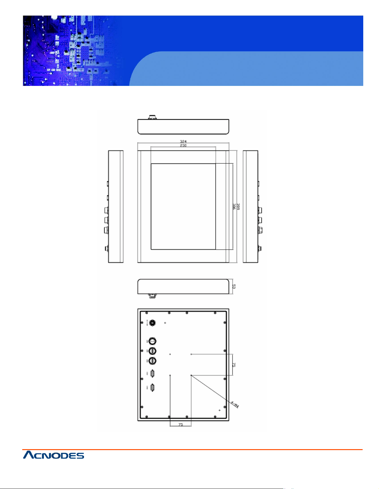
Dimension
399 (W) x324(H) x 53 (D) mm (PC H7591)
432 (W) x358(H) x 57 (D) mm (PC H7791)
470 (W) x389(H) x 60 (D) mm (PC H7991)
Environmental
Operating Temperature
0~50 ゚ C
Storage Temper ature
-20~60 ゚ C
Storage Hu midity
10~90% @40 non-c ondensing
Certificate
Me et CE/FC C C lass A
Page 8
PCH 7591
15 inch Atom Fanless Panel PC
© Copyrigh t 2012 Acnodes, Inc.
All rights reserved. Prod uct desc ript ion and product spe cificati ons
are subj ect to ch ange with out notice . For latest produ ct in format ion,
please visit Acnodes’ we b site at www.acnodes.com.
14628 Central Ave.
Chin o, CA91710
Tel:909.597.7588, Fax:909. 597.1939
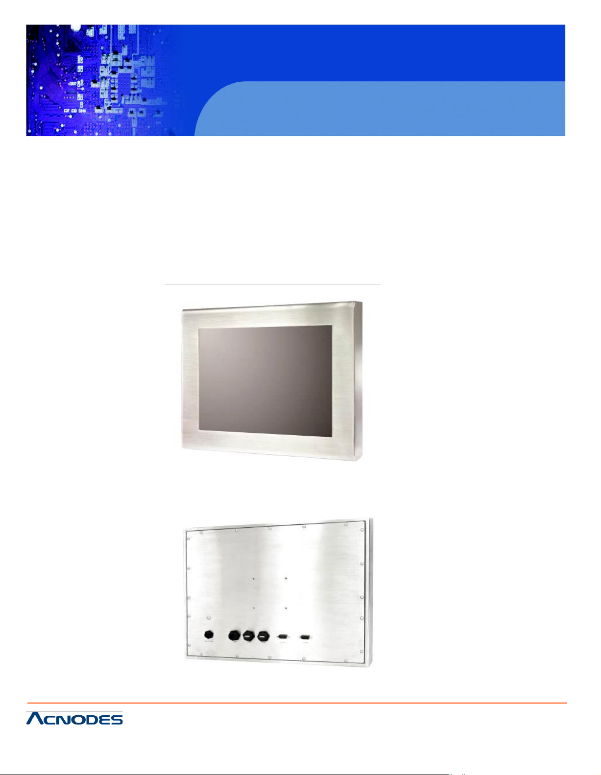
1.3 Brief Description of the PCH 7X91
The c ha ssis of the PCH 7X91 is m ade of stainless steel with an ultra slim profil e. I t i s built in the Intel
A tom N2 70 1.6GHz, FS B 533M H z, it is fan less. The m odel com es with a 15” ~19” inch TFT LCD
d isplay, total N EM A 4/IP 65 com pliant, s pace for one 2.5-inch H DD, resi stive touch s cree n, a D C
11~ 32V wide range power input. This industrial panel PC also features 2 CO M po rts, 2 U SB ports and
1 x Gigabit LA N port. It is ideal for use as a P C-based controll er for A utom otive, Logis tic P roc ess,
M ate rial s Handl ing, and Kios k applicati ons.
Figu re 1.1: Front View of
Figure 1.2: Rear View of
PCH7991
PCH7991
Page 9
PCH 7591
15 inch Atom Fanless Panel PC
© Copyrigh t 2012 Acnodes, Inc.
All rights reserved. Product description and product specifications
are subj ect to ch ange with out notice. For l atest product inform ati on,
please visit Acnodes’ web site at www.acnodes.com.
14628 Central Ave.
Chin o, CA91710
Tel:909.597.7588, Fax:909.597.1939
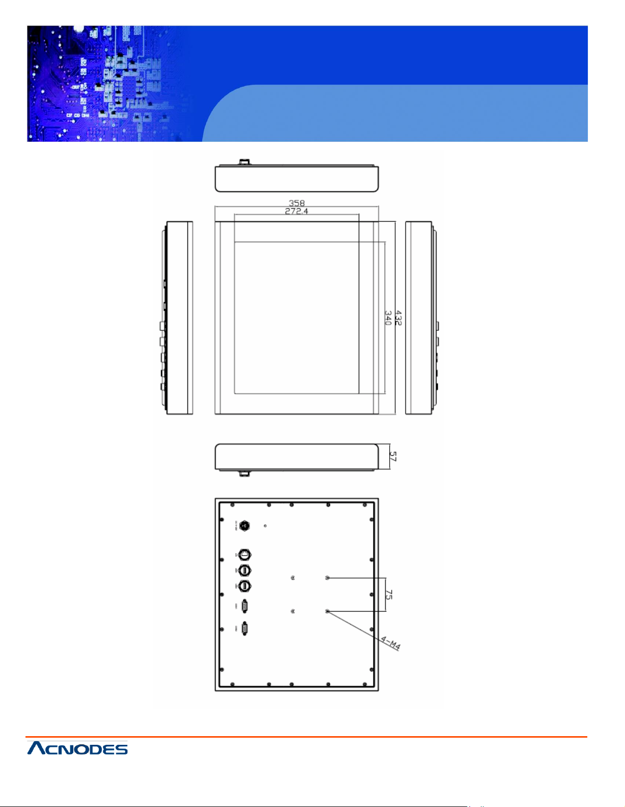
1.4 Chassis Dimensions
Figure 1.3: Dimensions of the PCH7591
Page 10
PCH 7591
15 inch Atom Fanless Panel PC
© Copyrigh t 2012 Acnodes, Inc.
All rights reserved. Prod uct desc ript ion and product spe cificati ons
are subj ect to ch ange with out notice . For latest produ ct in format ion,
please visit Acnodes’ we b site at www.acnodes.com.
14628 Central Ave.
Chin o, CA91710
Tel:909.597.7588, Fax:909. 597.1939
Figure 1.4 Dimensions of the PCH7791
Page 11
PCH 7591
15 inch Atom Fanless Panel PC
© Copyrigh t 2012 Acnodes, Inc.
All rights reserved. Product description and product specifications
are subj ect to ch ange with out notice. For l atest product inform ati on,
please visit Acnodes’ web site at www.acnodes.com.
14628 Central Ave.
Chin o, CA91710
Tel:909.597.7588, Fax:909. 597.1939
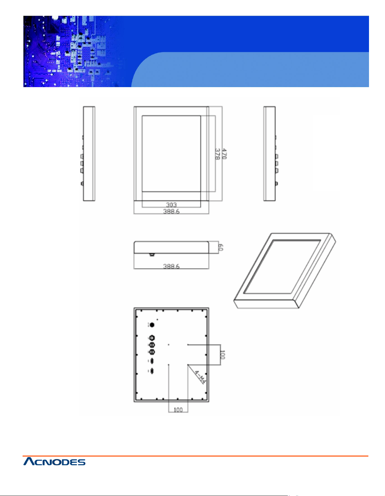
Figure 1.5 Dimensions of the PCH7991
Page 12

PCH 7591
15 inch Atom Fanless Panel PC
© Copyrigh t 2012 Acnodes, Inc.
All rights reserved. Prod uct desc ript ion and product spe cificati ons
are subj ect to ch ange with out notice . For lat est produc t in formati on,
please visit Acnodes’ we b site at www.acnodes.com.
14628 Central Ave.
Chin o, CA91710
Tel:909.597.7588, Fax:909. 597.1939
Chapter 2
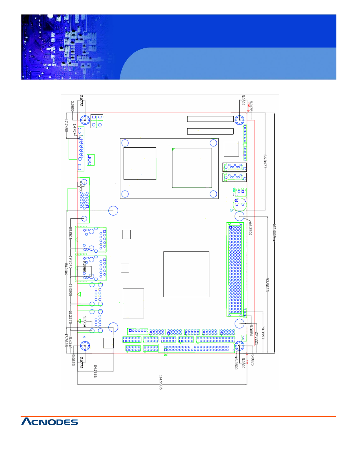
2.1 Mainboard Specifications
Figure 2.1: Mainboard Overview
Page 13
PCH 7591
15 inch Atom Fanless Panel PC
© Copyrigh t 2012 Acnodes, Inc.
All rights reserved. Product description and product specifications
are subj ect to ch ange with out notice. For l atest product inform ati on,
please visit Acnodes’ web site at www.acnodes.com.
14628 Central Ave.
Chin o, CA91710
Tel:909.597.7588, Fax:909. 597.1939
Page 14
© Copyrigh t 2012 Acnodes, Inc.
All rights reserved. Prod uct desc ript ion and product spe cificati ons
are subj ect to ch ange with out notice . For lat est produc t in formati on,
please visit Acnodes’ we b site at www.acnodes.com.
14628 Central Ave.
Chin o, CA91710
Tel:909.597.7588, Fax:909. 597.1939
PCH 7591
15 inch Atom Fanless Panel PC
Page 15
© Copyrigh t 2012 Acnodes, Inc.
All rights reserved. Product description and product specifications
are subj ect to ch ange with out notice. For l atest product inform ati on,
please visit Acnodes’ web site at www.acnodes.com.
14628 Central Ave.
Chin o, CA91710
Tel:909.597.7588, Fax:909. 597.1939
PCH 7591
15 inch Atom Fanless Panel PC
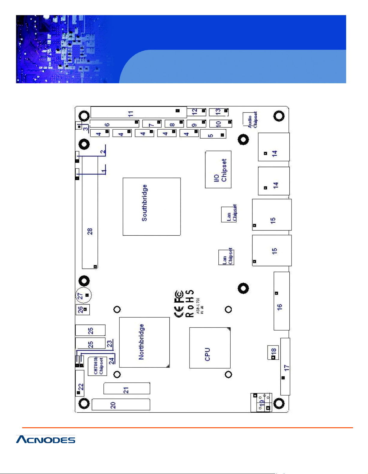
Figure 2.3: Connector and Jumper Locations
Page 16

© Copyrigh t 2012 Acnodes, Inc.
All rights reserved. Prod uct desc ript ion and product spe cificati ons
are subj ect to ch ange with out notice . For lat est produc t in formati on,
please visit Acnodes’ we b site at www.acnodes.com.
14628 Central Ave.
Chin o, CA91710
Tel:909.597.7588, Fax:909. 597.1939
PCH 7591
15 inch Atom Fanless Panel PC
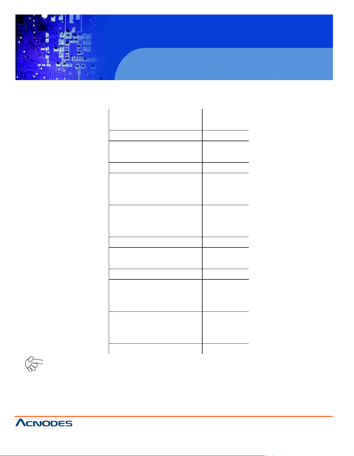
Speci ficatio
ns
Board S ize
165 x 115 mm
CP U S upport
Intel Atom N 270 1.6 GHz w ith 533MHz FS B
Chipset
Intel 9 45G SE + Intel IC H7M
Mem ory S upport
1x 200pin 533/400MHz DDR 2 SO -D IMM support, up to 2GB
S DR AM
Graphics
Intel Graphics Media Accel era tor 950V GA integrated in Intel
94 5GSE
18 -bit dua l-c hannel LVD S integrated i n In tel 945GS E
18 /24 bit dual-channel LVD S s upport by Chron tel CH 7308B
1 x DB 15 Female connecto r for external
Super I/O
W inbond W 83627UHG
BIOS
A ward BI OS
Storage
2 x S ATA C onnector
1 x Compact Flash II S lot
1 x 44-pin ID E C onnector
Network
2 x Gigabit E thernet Port by R J45 with LE D i ndicators E thernet controller :
2 x P CIe by one bu s Realtek 8111D
USB
4 x U SB 2.0 stack p ort for external
2 x US B 2.0 header for inte rnal
Serial
1 x R S23 2 po rt, D B9 connec tor for external (CO M1 ),
pin 9 w/5V /12V /Ring sel ect
1 x RS 232/422/485 sel ect header for i nternal (C OM2),
def au lt RS 232
4 x RS 232 header for internal (COM3 – C OM6)
Digital I/O
8-bit di gi tal I/O by header
4-bit di gi tal Input
4-bit digital O utput
Page 17

PCH 7591
15 inch Atom Fanless Panel PC
© Copyrigh t 2012 Acnodes, Inc.
All rights reserved. Product description and product specifications
are subj ect to ch ange with out notice. For l atest product inform ati on,
please visit Acnodes’ web site at www.acnodes.com.
14628 Central Ave.
Chin o, CA91710
Tel:909.597.7588, Fax:909. 597.1939
Battery
Support CR2 477 ba ttery by 2-pin header
Audio
Support Audio via Realtek ALC662 HD audio decoder
Support L ine-in, Line-out, MIC by 2x5-pin header
Printer
1x LPT port by 2x13-pin header
Keyboa rd
/Mouse
1x PS2 keyboard/mouse by 1x6 -pin wafer connector
Expansion Bus
1x PC 10 4+ connec tor (PCI master 4, jumper f or +3.3V &
5V se lect)
1x PCIe ( PCI-e 1x +SMBUS+USB2. 0 ) mini ca rd
Pow er
Management
DC12V input
Front I/O
by 2x5-pin header
Power on /off switc h
Reset switch
Power LED status
HDD LED status
Buzzer
Watchdog Timer
Software programmable 1 – 255 second by Super I/O
External I/O port
1 x COM Port (COM1)
4 x USB 2.0 Ports (stac k)
2 x RJ45 Gb E Port (10/100/1000Mbps)
1 x VGA Port
Temperature
Operating: 0 – 60 degre e C
Storage: -20 – 80 degree C
Humidity
5% - 95%, non-condensing, operating
Pow er
Consumption
12 V @1.45A (Intel N270 processor with 1GB DDR2 DRAM)
EMI /EMS
CE/FCC clas s A
Page 18

PCH 7591
15 inch Atom Fanless Panel PC
© Copyrigh t 2012 Acnodes, Inc.
All rights reserved. Prod uct desc ript ion and product spe cificati ons
are subj ect to ch ange with out notice . For latest produ ct in format ion,
please visit Acnodes’ we b site at www.acnodes.com.
14628 Central Ave.
Chin o, CA91710
Tel:909.597.7588, Fax:909. 597.1939
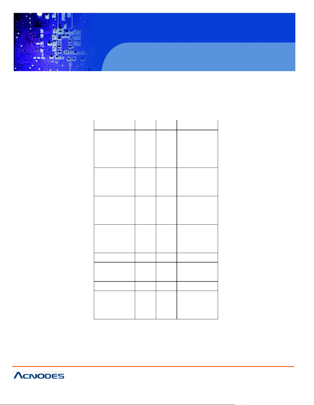
JVC CIO
PCI-104 VCCIO
Voltage
CLOSE
1-2
+3.3V (defaul t)
CLOSE
2-3
+5V
JCLR _CMOS
CMOS
CLOSE 1-2
NO RMAL
(de fault)
CLOSE 2 -3
CLEAR CMO S
2.2 Onboard Jumpers and Port Pinouts
1. JVCC IO (2.0 MM 1X3) PCI-104 port voltage selection jumper: selec t voltage for PC I-104+ device
2. JC LR _CMOS (2.0MM 1X3) CMOS clear jumper: CMOS clear operation will perm anently reset old
BIOS settings to factory defaults .
Procedures of C MOS c lear:
1. Turn off the system and unplug the power cord from the power outlet;
2. To clear the C MOS settings, us e the jumper cap to close pins 2 a nd 3 for about 3 seconds then
reinstall the jumper clip b ack to pins 1 and 2.
3. Pow er o n th e s ystem again;
4. When entering the POST sc reen, press the <D EL> ke y to enter CMOS Setup U tility to load optimal
defaults;
5. After the above operations, s ave changes and exit BIOS Setup.
Page 19

PCH 7591
15 inch Atom Fanless Panel PC
© Copyrigh t 2012 Acnodes, Inc.
All rights reserved. Product description and product specifications
are subj ect to ch ange with out notice. For l atest product inform ati on,
please visit Acnodes’ web si te at www.acno des. com.
14628 Central Ave.
Chin o, CA91710
Tel:909.597.7588, Fax:909. 597.1939
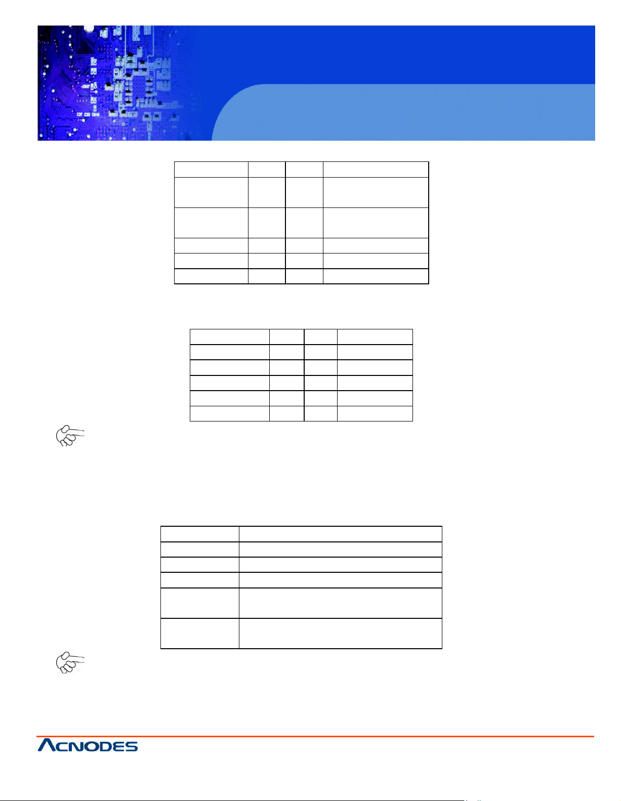
Pin #
Sign al
Name
1
KBDATA
2
MSD ATA
3
Ground
4
+5V
5
KBCLK
6
MSC LK
PIN#
Signal
Name
PIN1
VBAT
PIN2
Ground
Signal
N ame
Pin#
Pin#
Signal
N ame
D CD
1 2 R XD
TXD
3 4 D TR
G round
5 6 D SR
RTS
7 8 C TS
R I 9 10
N C
3. BAT (1.25.0MM 1X2) Ext. Battery port: a 3.3V battery is embedded to provide po wer for C MOS.
4.CO M2-C OM6 (2.0MM 2 X5) CO M2~COM6 port: up to 5 s tandard RS232 ports are provided. The y
can be use d direc tly via C OM adapter cable connection.
Note: C OM2 port is controlled by p ins No.8~1 0 of JCOM. For details, please refer to
desc ript ion of JCO M.
5.KB /MS (2.0MM 1X6 ) PS/2 ke yboard/mous e port: the port can be connected to PS/2 keyboard or
mouse via a dedicated adapter cable for direct use.
Page 20

PCH 7591
15 inch Atom Fanless Panel PC
© Copyrigh t 2012 Acnodes, Inc.
All rights reserved. Prod uct desc ript ion and product spe cificati ons
are subj ect to ch ange with out notice . For latest produ ct in format ion,
please visit Acnodes’ we b site at www.acnodes.com.
14628 Central Ave.
Chin o, CA91710
Tel:909.597.7588, Fax:909. 597.1939
Signa l Name
Pin#
Pin#
Signa l N ame
PSTB#
1 2 PD0
PD 1
3 4 D P2
DP3
5 6 D P4
DP5
7 8 D P6
DP7
9
10
ACK#
BU SY
11
12
PE
SL CT
13
14
AFD#
ER R#
15
16
INIT#
SL IN#
17
18
Ground
Ground
19
20
Ground
Ground
21
22
Ground
Ground
23
24
Ground
Ground
25
26
Ground
Signa l Name
Pin#
Pin#
Signa l N ame
GPIO20
1 2 G PIO 60
GPIO21
3 4 G PIO 61
GPIO22
5 6 G PIO 62
GPIO23
7 8 G PIO 63
Ground
9
10
+5V
6. LPT (2.0MM 2X13) Parall el port: a standard 26 pin parallel port is prov ided to connect parallel
peripherals as required.
7. GPIO (2.0MM 2X5) General-purpose input/output port: it provides a gro up of self-programming
interfaces t o customers for flexible use.
Page 21
PCH 7591
15 inch Atom Fanless Panel PC
© Copyrigh t 2012 Acnodes, Inc.
All rights reserved. Product description and product specifications
are subj ect to ch ange with out notice. For l atest product inform ati on,
please visit Acnodes’ web si te at www.acno des. com.
14628 Central Ave.
Chin o, CA91710
Tel:909.597.7588, Fax:909. 597.1939
S ig n a l N a m e
P in #
P in #
S ig n a l N a m e
A
1 2 Te r m in a l
R e s is t a n c e
B
3 4 Te r m in a l
R e s is t a n c e
Z
5 6 N C
Y
7 8 N C
G r o u n d
9
1 0
N C
S ig n a l N a m e
P in #
P in #
S ig n a l N a m e
+ 5 V
1 2 + 5 V
U S B _ P 6 _ D N
3 4 U S B _ P 7 _ D N
U S B _ P 6 _ D P
5 6 U S B _ P 7 _ D P
G r o u n d
7 8 G ro u n d
N C 9 1 0
G ro u n d
J C O M
F u n c t i o n
C L O S E 1 - 2
C O M 1 P i n 9 = R I (d e f a u l t )
C L O S E 3 - 4
C O M 1 P in 9 = + 5 V
C L O S E 5 - 6
C O M 1 P in 9 = + 1 2 V
C L O S E 7 - 9
C L O S E 8 - 1 0
C O M 2 F O R R S 2 3 2 F R O M C O M 2
(d e f a u l t)
C L O S E 9 - 11
C L O S E 1 0 - 1 2
C O M 2 F O R R S 4 8 5 / R S 4 2 2 F R O M
C O M 2 2
8 . C O M 2 2 (2 . 0 M M 2 X 5 ) : it p r o v id e s s e le c t a b le R S 4 2 2 / 4 8 5 s e r ia l s ig n a l o u t p u t .
9 . U S B 4 (2 . 0 M M 2 X 5 ) F r o n t U S B c o n n e c t o r : it p r o v id e s t w o U S B p o rt s v ia a d e d ic a t e d U S B
a d a p t e r c a b le .
N o t e :
B e f o r e c o n n e c t io n , m a k e s u re t h at p in o u t o f t h e U S B a d a p t e r is in a c c o rd a n c e w it h t h a t o f t h e s a i d
t a b le s . A n y in c o n f o r m it y m a y c a u s e s y s t e m d o w n a n d e v e n h a rd w a re d am a g e s .
1 0 . J C O M (2 . 0 M M 2 X 6 ) C O M 1 / 2 s e t u p j u m p e r: p i n 1 ~ 6 a r e u s e d t o s e le c t s ig n a l o u t o f p in 9 o f
C O M 1 p o r t ; p in 7 ~ 1 2 a r e u s e d t o s e le c t o u t p u t t y p e f o r C O M 2 p o r t (R S 2 3 2 o r R S 42 2 /4 8 5 ).
N o t e :
1 . A s d e t e r m in e d b y i ts h a r d w a r e d e s ig n , th e b o a r d f e a t u r e s f u ll- d u p le x R S 4 8 5 c o m m u n ic a t io n . L ik e
R S 4 2 2 , a f o u r - w ir e c o n n e c t io n i s n e c e s s a r y.
2 . S in c e C O M 2 a nd C O M 2 2 u s e t h e s a m e a d d r e s s , th e y c a n n o t w o r k a t t h e s a m e t im e .
Page 22
PCH 7591
15 inch Atom Fanless Panel PC
© Copyrigh t 2012 Acnodes, Inc.
All rights reserved. Prod uct desc ript ion and product spe cificati ons
are subj ect to ch ange with out notice . For latest produ ct in format ion,
please visit Acnodes’ we b site at www.acnodes.com.
14628 Central Ave.
Chin o, CA91710
Tel:909.597.7588, Fax:909. 597.1939
Signa l N ame
Pin#
Pin#
Sign al Name
R ESET
1 2 Ground
ID E_PDD 7
3 4 IDE_PD D8
ID E_PDD 6
5 6 IDE_PD D9
ID E_PDD 5
7 8 IDE_PD D10
ID E_PDD 4
9
10
IDE_PD D11
ID E_PDD 3
11
12
IDE_PD D12
ID E_PDD 2
13
14
IDE_PD D13
ID E_PDD 1
15
16
IDE_PD D14
ID E_PDD 0
17
18
IDE_PD D15
Ground
19
20
NC
D REQ
21
22
Ground
IOW#
23
24
Ground
IOR #
25
26
Ground
IOC HR DY
27
28
Ground
D AC K#
29
30
Ground
IR Q14
31
32
NC
Address 1
33
34
IDE_PD IAG
Address 0
35
36
Add res s 2
C hip selec t 0
37
38
Chip s elect 1
Activit y
39
40
Ground
+5V
41
42
+5V
Ground
43
44
NC
11. I DE (2.0MM 2X22) IDE connector: the motherboard pro vides a 44-pin IDE connect or for
connec tion of 2.5' IDE ha rd disk drivers and supports up to 2 IDE devices .
N ote:
If tw o IDE devices are connecte d, C F card connection cannot be realized.
Page 23
PCH 7591
15 inch Atom Fanless Panel PC
© Copyrigh t 2012 Acnodes, Inc.
All rights reserved. Product description and product specifications
are subj ect to ch ange with out notice. For l atest product inform ati on,
please visit Acnodes’ web site at www.acnodes.com.
14628 Central Ave.
Chin o, CA91710
Tel:909.597.7588, Fax:909. 597.1939
S ig n a l N a m e
P in #
P in #
S ig n a l N a m e
H D L E D +
1 2 P O W E R
L E D +
H D L E D -
3 4 P O W E R L E D -
G r o u n d
5 6 P W R B T N
R E S E T
7 8 G ro u n d
B U ZZ E R +
9
1 0
B U Z Z E R -
S ig n a l N a m e
P i n #
P i n #
S ig n a l N a m e
F R O N T- O U T- L
1 2 L IN E IN _ R
A U D _ A G N D
3 4 A U D _ A G N D
F R O N T- O U TR
5 6 L IN E IN _ L
A U D _ A G N D
7 8 A U D _ A G N D
F R O N T- M IC 1
9
1 0
A U D _ A G N D
1 2 . F _
PA
N E L (2 .0 M M 2 X 5 ) F ro n t pa n e l c o nn e c t o r
P IN 1 & 3 : Th e y a re u s e d to c o n n e c t h a r d d is k a c tiv ity L E D . T h e L E D b lin k s w h e n th e h a r d d is k
r
e a d in g o r w r
itin
g d a ta .
P IN 2 & 4 : Th e y a re u s e d t o c o n ne c t p o w e r L E D . W h e n th e s y s te m i s p o w e r e d o n o r u n d e r S 0
th e L E D is n o rm a l ly o n ; w h e n th e s y s te m is u n d e r S 4
/S
5 s ta te , th e L E D is off.
is
/S
1 s ta te ,
P IN 5 & 6 : T h e y a r e u s e d to c o n n e c t p o w e r s w itc h b u tto n . T h e tw o p in s a r e d is c o n n e c te d u n d e r n o r m a l
c o n d
itio
n .
Yo
u m a y s h o r t th e m te m p o r a r ily to r e a
liz
e s y s te m s ta r tu p & s h u td o w n o r a w a k e n th e s y s te m
fr o m s le e p s ta te .
P IN 7 & 8 : Th e y a re u s e d to c o n n e c t r e s e t b u tto n . T he tw o p in s a r e d is c o n n e c te d u n d e r n o rm a l
c o n d
itio
n .
Yo
u m a y s h o r t th e m te m p o r a r ily to r e a
liz
e s y s te m r e s e t.
P IN 9 & 1 0 : Th e y a re u s e d to c o n n e c t a n e x te r n a l b u z z e r.
N o te :
W h e n c o n n e c tin g L E D s a n d b u z z e r, p a y s p e c ia l a tte n tio n to th e s ig n a l p o la ri ty.
M a k e s u re th a t th e c o nn e c to r p i n s h a v e a o n e - to - o ne c o r re s po n de n c e w ith c h a s s is w i ri n g , o r i t m a y
c a u s e b o o t u p fa ilu r e .
1 3 . F _ A U D IO (2 .0 M M 2 X 5 ) Fr o n t A u d io: A n o n b o a r d R E A LTEL A L C 6 6 2 C O D E C is u s e d to p ro v i d e
h ig h - q u a lity a u d i o I/O p o r ts ; L in e O u t c a n b e c o n n e c te d to a h e a d p h o n e o r a m p lif ie r; L in e In is u s e d f o r
th e c o n ne c tio n o f e x te r n a l a u d io s o u r c e v i a a L in e in c a b le ; M ic is th e p o r t fo r m ic r o p h o n e in p u t a u d io .
N o te :
T h e b o a r d o n ly s u p p o r ts m o n o m ic ro p h o n e in p u t.
Page 24

PCH 7591
15 inch Atom Fanless Panel PC
© Copyrigh t 2012 Acnodes, Inc.
All rights reserved. Prod uct desc ript ion and product spe cificati ons
are subj ect to ch ange with out notice . For latest produ ct in format ion,
please visit Acnodes’ we b site at www.acnodes.com.
14628 Central Ave.
Chin o, CA91710
Tel:909.597.7588, Fax:909.597.1939
4.2.2 UNPACKING PROCEDURE
To unpack the APM series industrial monitor, follow the steps below:
WARNING:
The front side LCD screen has a protective plastic cover stuck to the screen. Only remove the plastic cover
after the APM series industrial monitor has been properly installed. This ensures the screen is protected during the installation process.
Step 1: Use box cutters, a knife or a sharp pair of scissors to open the seal on the top side of the external
(second) box.
Step 2: Open the external (second) box.
Step 3: Use box cutters, a knife or a sharp pair of scissors the seal on the top side of the internal (first)
box.
Step 4: Lift the monitor out of the boxes.
Step 5: Remove both polystyrene ends, one from each side.
Step 6: Pull the plastic cover off the APM series industrial monitor.
Step 7: Make sure all the components listed in the packing list are present.
4.2.3 PACKING LIST
All the monitors in the APM series are shipped with the following components:
APM5121 / APM5151 industrial LCD monitor
1 x Power cable for terminal block
1 x VGA cable
1 x Screw set
1 x User manual on CD-ROM
1 x Touch screen RS-232 cable / touch pen / driver CD-ROM
*1 x 45W AC power adapter with AC 90V ~ 264V @ 1A input and DC +12V
@3.75A output / AC power cord
* External 45W power adapter only supports 0°C ~ 40°C operating temperature
If any of these items are missing or damaged, contact the distributor or sales representative imme
diately.
Page 25

PCH 7591
15 inch Atom Fanless Panel PC
© Copyrigh t 2012 Acnodes, Inc.
All rights reserved. Product description and product specifications
are subj ect to ch ange with out notice. For l atest product inform ati on,
please visit Acnodes’ web site at www.acnodes.com.
14628 Central Ave.
Chin o, CA91710
Tel:909.597.7588, Fax:909. 597.1939
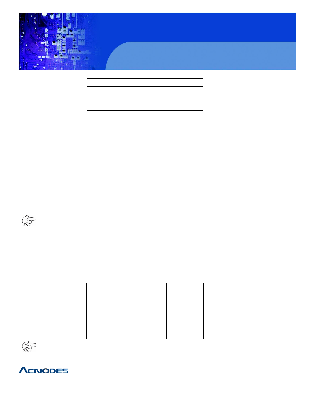
Pin#
Signa l Name
1
Ground
2
+12V
3
Rotation
detection
Pin#
Signa l N ame
1
+12V
2
G round
14. U SB 1/2 R ear USB connector: it provide s up to 4 USB2.0 po rts.
15. LAN 1/2 R ear LAN connectors: 2 standard 1000M RJ-45 Ethernet ports are provided. LIN K
LED (green) and AC TIVE LED (yellow) respec tively loc ated at the left-hand and righ t-hand side of the
Ethernet port indicate the activity and transmission state of LAN .
16. VGA (Video Graphic Arra y): GMA950 GPU is integrated to provide high-quali ty video ou tpu t.
17. C OM1 R ear serial port: standard DB9 serial port is provided to mak e a d irec t connection to s eria l
devices.
18. FAN (2.54MM 1X3) Fan connector: cooling fans can be connected direc tly for use. You may set
the rotation condit ion of cooling fan in PC H ea lth Status menu of BIOS Setup.
N ote: Output po wer of coo ling fan must be limit ed under 5W.
19. AT12V (5.0MM 1X2) 12V System power input connector
N ote:
Make s ure that the vo ltage of po wer supply is DC(12±5%)V before power on, or it may caus e boot up
failure a nd even system damage.
Page 26
PCH 7591
15 inch Atom Fanless Panel PC
© Copyrigh t 2012 Acnodes, Inc.
All rights reserved. Prod uct desc ript ion and product spe cificati ons
are subj ect to ch ange with out notice . For latest produ ct in format ion,
please visit Acnodes’ we b site at www.acnodes.com.
14628 Central Ave.
Chin o, CA91710
Tel:909.597.7588, Fax:909.597.1939
Signal Name
Pin#
Pin#
Signa l Nam e
+5V
1 2 +5V
Gro und
3 4 Ground
+3.3V
5 6 +3.3 V
A0M
7 8 A4M
A0P
9
1 0
A4P
Gro und
11
1 2
Ground
A1M
13
1 4
A5M
A1P
15
1 6
A5P
Gro und
17
1 8
Ground
A2M
19
2 0
A6M
A2P
21
2 2
A6P
Gro und
23
2 4
Ground
CLK1M
25
2 6
CLK2M
CLK1P
27
2 8
CLK2P
Gro und
29
3 0
Ground
SC _DDC
31
3 2
SD_DD C
Gro und
33
3 4
Ground
A3M
35
3 6
A7M
A3P
37
A3M
A7P
NC
39
4 0
NC
20. LVD S2 for dual 24 bit 24-bit LVDS output connector: Fully s upported b y C HR ONTEL CH 7038B
chips et, the interf ace features single and dual channel 18-bit and 24-bit output with max imum
resolution support up to 1600*1200. The format of conne cted displ ay screen is OPENLDI. Model
name of the in terface con nec tor is Hirose D F13-4 0DP-1.25V.
Page 27
PCH 7591
15 inch Atom Fanless Panel PC
© Copyrigh t 2012 Acnodes, Inc.
All rights reserved. Product description and product specifications
are subj ect to ch ange with out notice. For l atest product inform ati on,
please visit Acnodes’ web site at www.acnodes.com.
14628 Central Ave.
Chin o, CA91710
Tel:909.597.7588, Fax:909. 597.1939
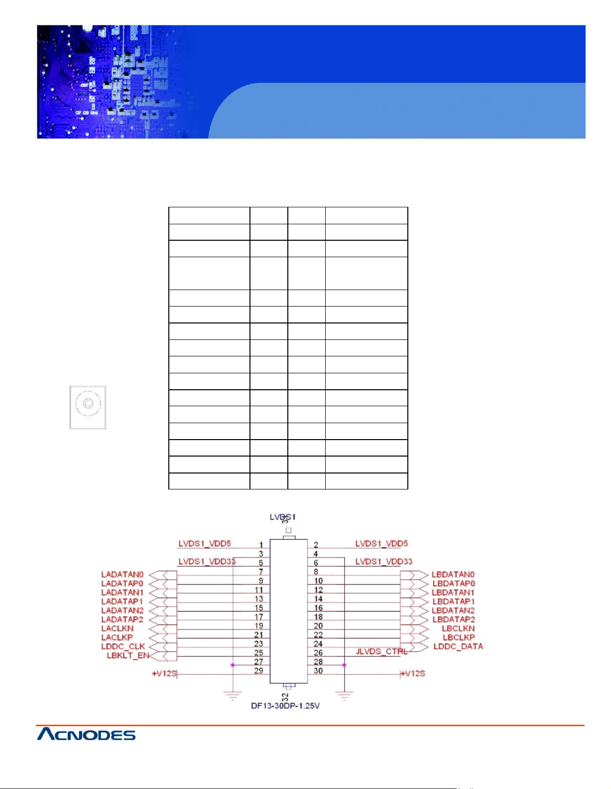
Signal
Nam
e
Pin#
Pin#
Signal
Nam
e
LVDS
1_V DD 5
1 2 LVD
S1_V
DD 5
Ground
3 4 Ground
LVDS
1_V DD 3
3
5 6 LVD
S1_V
DD 3
3
LAD ATA N0
7 8 LBD ATA N0
LAD ATA P0
9
10
LBD ATA P0
LAD ATA N1
11
12
LBD ATA N1
LAD ATA P1
13
14
LBD ATA P1
LAD ATA N2
15
16
LBD ATA N2
LAD ATA P2
17
18
LBD ATA P2
LAC LKN
19
20
LBC LKN
LAC LKP
21
22
LBC LKP
LDD C _CLK
23
24
LDD C _DATA
LBK LT _EN
25
26
J LVD S_C T RL
Ground
27
28
Ground
+V 12S
29
30
+V 12S
21. LVD S1 fo r d u al 18 b it
the interface features
1600*1200. T he form at of connected di splay screen i s SP W G. M odel nam e of the i nterface c onnector
is H irose DF
13-30DP
18-b
it LV DS ou tp ut co n
singl
e and dual channel 18 -bit output w ith m
necto
-1.25V.
r : Ful ly supported by INT
axim
um resolution support u p to
EL945G
SE chipset,
Page 28
PCH 7591
15 inch Atom Fanless Panel PC
© Copyrigh t 2012 Acnodes, Inc.
All rights reserved. Prod uct desc ript ion and product spe cificati ons
are subj ect to ch ange with out notice . For latest produ ct in format ion,
please visit Acnodes’ we b site at www.acnodes.com.
14628 Central Ave.
Chin o, CA91710
Tel:909.597.7588, Fax:909. 597.1939
Pin#
Signa l N ame
1
+12V
2
+12V
3
G rou nd
4
G rou nd
5
EN ABKL
6
CTRBKL
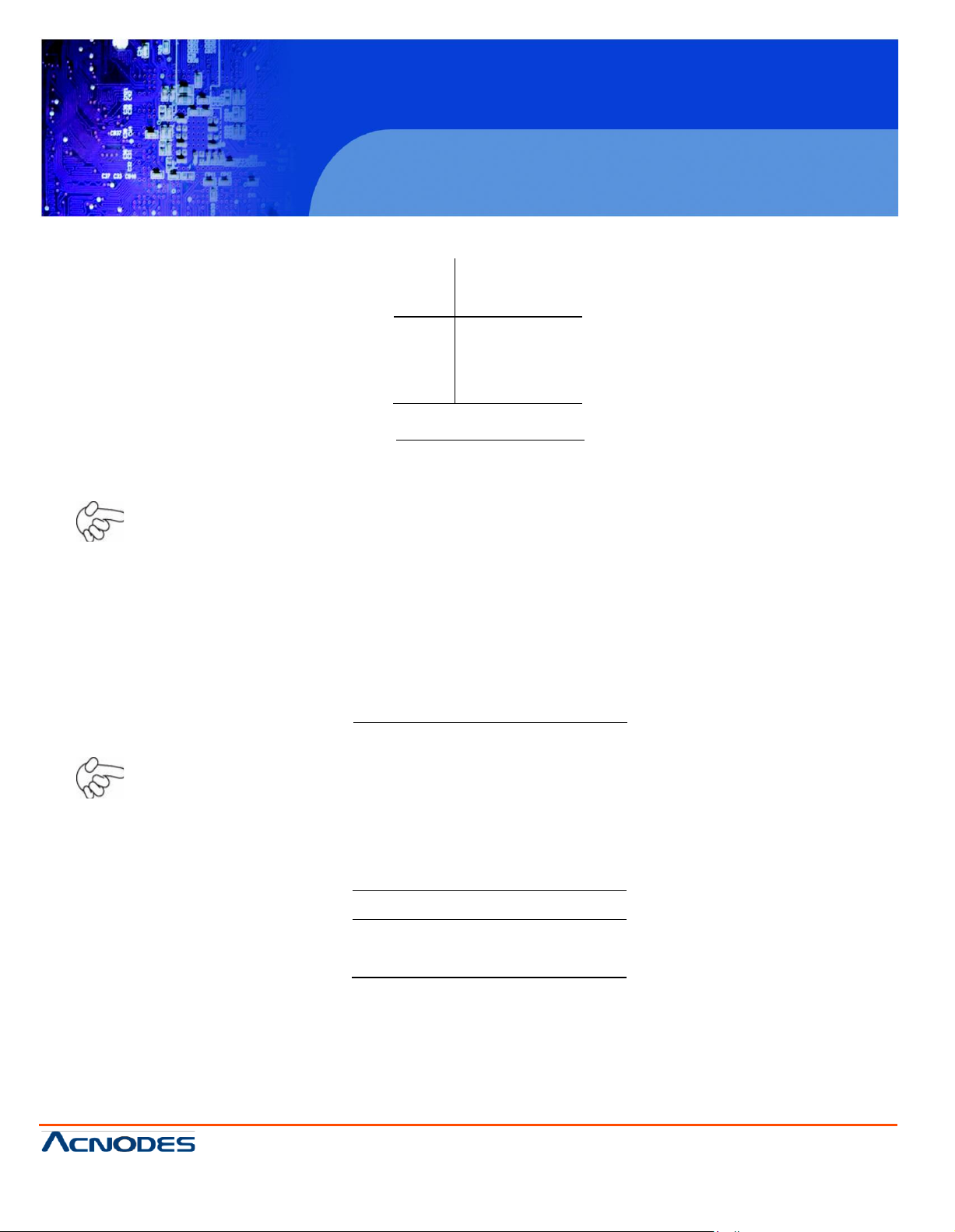
JBGT_CTR L
Function
C lose 1 -2
LEVEL
C lose 2-3
PWM
JBKLT_EN
Function
C lose 1 -2
LVD S1
C lose 2-3
LVD S2
22. B KL (2.0MM 1X5) Backlight control connecto r for LVDS1/2
N ote
Pin# 6, Backlight control voltage from 0~ 5V
23. JB GT_CTRL (2.0MM 1X6) Backlight Control jum per set ting for LVDS1/2
N ote: please ch eck first your LVD S panel back light control by LEVEL or PWM?
24. JB KLT_EN (2.0MM 1X3) Selection of LVDS1/2
Page 29

PCH 7591
15 inch Atom Fanless Panel PC
© Copyrigh t 2012 Acnodes, Inc.
All rights reserved. Product description and product specifications
are subj ect to ch ange with out notice. For l atest product inform ati on,
please visit Acnodes’ web site at www.acnodes.com.
14628 Central Ave.
Chin o, CA91710
Tel:909.597.7588, Fax:909. 597.1939
Pin#
Signa l
Nam e
1
+5V
2
Ground
25. SATA1/2 SATA Connectors: two SATA connectors are provided, with tran sfer speed up to
3.0Gb/s .
26. C N1 (2.5MM 1X2 ): an onboard 5V outp ut connector is reserved to provide power for IDE/SATA
devices.
N ote:
Output current of the connec tor mus t n ot b e abov e 1A.
27. B Z Buzz er: onboard buzzer
28. PCI- 104+ PCI-104 connector: it conforms to standard PC I-104 (PCI only) spec ification .
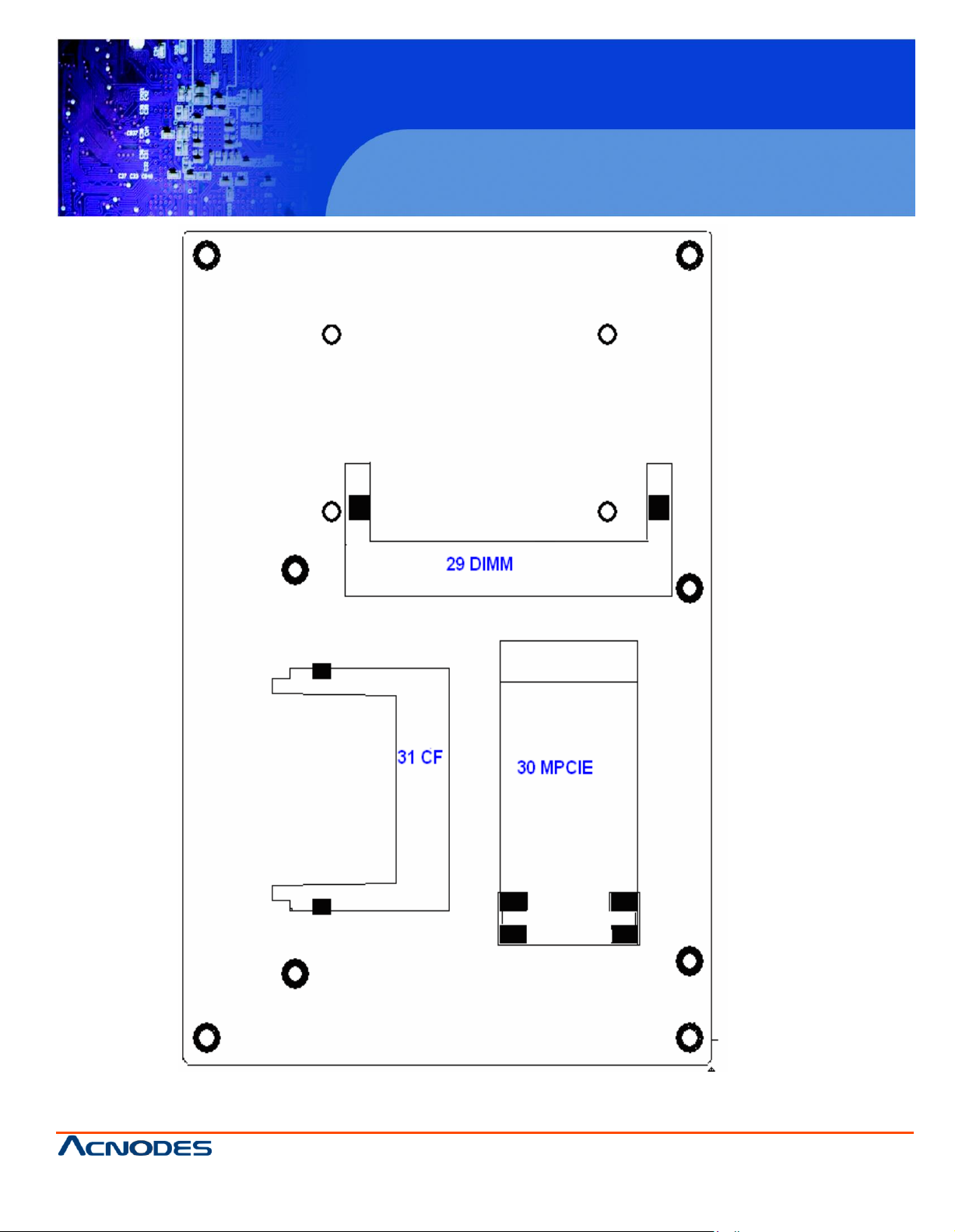
29. SO-DIMM Memory socket: the socket is located at the bac kside of the board and supports
200PIN 1.8V DD RII400/533 SO-DIMM memory module up to 2G. If a DDR II667/800 memory m odule
is installed, the sy stem will redu ce the DRAM frequency to 533MHz .
30. MPCIE Mini PC I-E slot: it supports MINI PCI-E devices with USB2.0, SMBU S and PCI-E signal.
31. CF CF Card Slot: it is located at the backs ide of the board and s erve s as an insert interface for
Type I and Type II Compact Fla sh card. The o peratin g voltage of CF c ard can be set as 3. 3V or 5V.
The default setting of the produc t is 3.3V.
Page 30

PCH 7591
15 inch Atom Fanless Panel PC
© Copyrigh t 2012 Acnodes, Inc.
All rights reserved. Prod uct desc ript ion and product spe cificati ons
are subj ect to ch ange with out notice . For latest produ ct in format ion,
please visit Acnodes’ we b site at www.acnodes.com.
14628 Central Ave.
Chin o, CA91710
Tel:909.597.7588, Fax:909. 597.1939
Chapter 3
3.1 Operations after POST Screen
After CMOS dis charge or BIO S flashing operation, the s ystem will display the following screen for your
fu rther operation. Pres s F1 key to continue or Del key to enter CMOS Setup.
Phoeni x – AwardBIOS v6.00PG,
Copyright ©
ASB-L
701 V
Main
Processor : Intel®
M
emory Testing
CPU Brand Name : Intel®
C1E BIOS Supported
Hyper-Threading
1984-2007,
019
Atom™ 1.60GHz(133x12)
:515008K OK + 8M
Atom™ CPU N270
Technolog
M
emory Frequency
IDE
Channel 0 Mas ter : N
I
DE
Channel 0 Slave
IDE
Channel 1 Mas ter : N
I
DE
Channel 1 Slave
For DDR 2 533
: None
: None
CMOS
checksum
error – Defaults
Press
F1
to conti
08/14/
2010-
nue, DEL to enter SETUP
Silv
erthrone-6A7
After optimizing an d e xiting CMOS Setup, the PO ST screen display ed f or the first time is as follows
a nd includes bas ic information on BIOS, C PU , memory, and storage d evices.
Phoeni x – AwardBIOS v6.00PG,
Copyright ©
1984-2007,
An Energy Star Ally
Phoenix T
y CPU D
one
one
9KAPXC-00
Phoenix T
echnologies,
shared memo
etected (Hyper-Threading Technology
loaded
An Energy Star Ally
echnologies,
LTD
ry
@1.60GHz
LTD
Enabled)
ASB-L
701 V
019
Main
Processor : Intel®
M
emory Testing
CPU Brand Name : Intel®
C1E BIOS Supported
Hyper-Threading
Atom™ 1.60GHz(133x12)
:515008K OK + 8M
Atom™ CPU N270
Technolog
y CPU D
shared memo
etected (Hyper-Threading Technology
M
emory Frequ ency
IDE
Channel 0 Master : N
I
DE
Channel 0 Slave
IDE
Channel 1 Master : N
I
DE
Channel 1 Slave
For DDR2 533
one
: None
one
: None
Press
DEL
to
08/14/
enter SETUP, F12 to
2010-
Silv
erthrone-6A7
Enter Boot
9KAPXC-00
Press F12 key to enter Boot Menu during POST, as s ho wn by the follow ing figure.
== Select a Boot First de vice ==
@1.60GHz
Menu
Boot Menu
ry
Enabled)
Page 31

PCH 7591
15 inch Atom Fanless Panel PC
© Copyrigh t 2012 Acnodes, Inc.
All rights reserved. Product description and product specifications
are subj ect to ch ange with out notice. For l atest product inform ati on,
please visit Acnodes’ web site at www.acnodes.com.
14628 Central Ave.
Chin o, CA91710
Tel:909.597.7588, Fax:909. 597.1939
? Standard CMO S
Features
? Advanced BIOS Feat ures
? Advanced Chipset
Features
? Inte grated Peripherals
? Power Management
Setup
? PnP/PC I Configurations
? PC H ealth Status
Load Fail-Safe Defaults
Load Optimized
Defaults
Set Adm inistrator
Pass word
Set User Password
Save & Exit Setup
Exit W ithout Saving
Esc : Quit ??? ? : Select Item
F10 : Save & Exit Setup
Time, D ate, Hard Disk Type…
+ Removable
+Hard Dis k
+CDR OM
LAN
??:Mo ve Enter:Ac cept F4:Exit
3.2 Standard CMOS Features
Press [D el] key to ent er BIOS Setup utility during PO ST, and then a m ain menu containing system
s ummary inform at ion will appear.
Phoenix – Award BIOS C MOS Setup U tility
Page 32

PCH 7591
15 inch Atom Fanless Panel PC
© Copyrigh t 2012 Acnodes, Inc.
All rights reserved. Prod uct desc ript ion and product spe cificati ons
are subj ect to ch ange with out notice . For latest produ ct in format ion,
please visit Acnodes’ we b site at www.acnodes.com.
14628 Central Ave.
Chin o, CA91710
Tel:909.597.7588, Fax:909. 597.1939
Standard CMOS Features
Use this m enu to modify basic system configurations such as tim e, date and etc.
A dvanced B IOS Features
Use this m enu configure advanced features of Awar d® BIOS.
A dvanced C hipset Features
Use this m enu to change the values in the chipset regis ters and optimize your system
performance.
Integrated Peripherals
Use this m enu to spec ify your s ettings for integrated peripherals.
Power Management Setup
U se this menu to s pecify your settings for power management.
PnP/PC I Configurations
This menu is valid only if your system s upports PnP/PCI.
PC H ealth Status
This menu shows the current status of your PC.
Load Fail-Safe Defaults
Use this m enu to load Fail-Safe defaults into BIOS for the m ost stable, and minimal-performance
system operations.
Page 33

PCH 7591
15 inch Atom Fanless Panel PC
© Copyrigh t 2012 Acnodes, Inc.
All rights reserved. Product description and product specifications
are subj ect to ch ange with out notice. For l atest product inform ati on,
please visit Acnodes’ web site at www.acnodes.com.
14628 Central Ave.
Chin o, CA91710
Tel:909.597.7588, Fax:909. 597.1939
Load O ptim ized Defaults
Use t his m enu to load factory settings into BI OS f or optimal- performance system operations.
S et Adm inistrator Passw ord
Use t his m enu to set Administrator password.
S et User P assw ord
Use t his m enu to set user password.
S ave & E xit S etup
Save all changes t o the CMO S and exit BIO S Setup.
Exit Without Saving
The f ollowing figure s hows the items of Standard CMOS Features menu , whic h may exclude any
Abandon all changes to the CMOS and exit BIOS Setup.
m odifiable subitem or c ontai n one o r more modifiabl e subitems . Use arro w keys to select the i tems to
b e m odified and <PgUp> or < PgD n> key to s elect desired setti ngs.
Phoenix – A wardBIOS CMOS Setup Utilit y
Standard CMOS
Features
Page 34

PCH 7591
15 inch Atom Fanless Panel PC
© Copyrigh t 2012 Acnodes, Inc.
All rights reserved. Prod uct desc ript ion and product spe cificati ons
are subj ect to ch ange with out notice . For latest produ ct in format ion,
please visit Acnodes’ we b site at www.acnodes.com.
14628 Central Ave.
Chin o, CA91710
Tel:909.597.7588, Fax:909. 597.1939
Date
T his item allows y ou to set a desired sys tem da te (u sually current date). T he date form at is
< day>< m onth><
date><year>
.
Day It is a read-only and b ios-def ined weekday att ribu te ranging from S un (Su nda y) to S at
(S aturday).
M o nth It i s a m onth attribute rangi ng fro m Jan (January) to D ec (Decem ber).
Date It is a date attribute rangi ng fro m 1 to 31 and can be m odified via num eric keys.
Ye ar It i s a user-d ef ined year attri bute.
Tim e
T his item allows you to set a desi red s ys tem tim e (usually c u rrent tim e). T he tim e form at is
< hour><m i nute><s econd>.
Ch an n el 0 M aster / Ch an n el 0 S lave
Ch an n el 1 M aster / Ch an n el 1 S lave
P ress P gUp/<+ > or P gDn/< -> key to sel ec t am ong M an ual, None an d A uto type. Note that the
s pecifica tion of your dri ve device m us t be in com plianc e with the contents of D ri ve Table. If the
i nformat ion regi stered in this item i s not correc t, your hard disk wi ll not work properly; if your ha rd di
s
pecifica tion is not found or does not conform to or the D ri ver Tabl e, you m ay select M anual type to set
th e specific ation m anually.
If you c hoose M anual, you wi ll be requested to enter relevant inform ation in the foll owing entries.
K eyboard input i s also supported. F or deta ils, you m ay refer to the instructive m a teri als provided by
d istributor or de vice m anufacturer.
If a S CS I HD D devic e is used, set thi s item to "NO NE ".
If a C D-ROM drive i s connected to the H DD port, se t this item to "N ONE "
AccessMo d e Option s are: Auto, N orm al, Large and LB A
C ylin d er Num ber of c ylinders
Head Num ber of heads
P reco m p W rite precom pensation cyl inder
L an din g Z o ne Head l and ing zone
H alt on
T he item allow s you to d eterm in e w hen the s ystem will s top. Options are: No Errors; A ll E rrors; A ll,
B ut K eyboard.
N o Erro rs Th e syste m b oo t will no t stop f or an y e rro r.
All Erro rs W he ne ver th e BI OS d et ect s a no n -fa tal e rro r, t he syste m b o ot will
sto p .
All, Bu t Ke yb o ard Th e syste m b o ot w ill n ot sto p f or a ke yb o ard e rro r b ut sto p f or all
o th er e rr o rs a s d et ect ed b y BIO S. (d e fa
ult)
sk
Page 35

PCH 7591
15 inch Atom Fanless Panel PC
© Copyrigh t 2012 Acnodes, Inc.
All rights reserved. Product description and product specifications
are subj ect to ch ange with out notice. For l atest product inform ati on,
please visit Acnodes’ web site at www.acnodes.com.
14628 Central Ave.
Chin o, CA91710
Tel:909.597.7588, Fax:909. 597.1939
? CPU Featu re [Press
Enter]
Item Help
? Hard D isk Bo ot Priority [Press
Enter]
Virus Warn ing
[Disab led]
CPU L1 & L2 Cache
[Enab led]
Men u L eve l?
H yper-Th readin g Techno logy
[Enab led]
Q uick Pow er On Self Test
[Enab led]
First Boot Device
[Remo vable]
S econ d Bo ot D evice [H ard
D isk]
Third Boot Device
[CDROM]
Boot Other Device
[Enab led]
PX E Boot Fo r On board LAN 1 [Disable]
PX E Boot Fo r On board LAN 2 [Disable]
Boot Up Num Lo ck Status [O n]
G ate A 20 Option [Fast]
3.3 Advanced BIOS Features
Phoenix – AwardBIOS CMOS Setup Utility
Advanced BIOS Fea tures
Page 36

PCH 7591
15 inch Atom Fanless Panel PC
© Copyrigh t 2012 Acnodes, Inc.
All rights reserved. Prod uct desc ript ion and product spe cificati ons
are subj ect to ch ange with out notice . For latest produ ct in format ion,
please visit Acnodes’ we b site at www.acnodes.com.
14628 Central Ave.
Chin o, CA91710
Tel:909.597.7588, Fax:909. 597.1939
X APIC Mode
[Enab led]
MPS Version Control Fo r OS [1.4]
O S Select Fo r DRAN > 64MB
[N on-OS2]
Small Logo [EPA] Sh ow
[Disab led]
Security Option [Setup]
??? ? :Mo ve En t er:S ele ct +/-/P U/P D:Va lue F1 0 :S ave ES C:E xit F1 :G e ne ral Help
F5: P revio us Va lu e s F6 : Fa il-S af e Def au lts F7 : O pt im iz ed De fa u lt s
C PU Feature
The item has the followin g options:
Delay Prior To Thermal [ 16 Min] (This item allows you to set the duration of entering CPU thermal
t hrottling.)
C1E Funct ion [Auto] CPU Power-s aving State Enable C on trol
CPU C State Capability [C1 ] CPU Power-saving Sta te Control
Exec ute Disab le Bit [Enable] (Virus Protection Technology)
H ard D isk Boot Priority (ID E Storage Devic e Boot Pri ority)
This item is used to spec ify boot priority of IDE devices . Press " Enter" key for detailed s etting.
Virus Warning
This item has two options: "Dis abled" and "Enabled".
C PU L1 & L2 Cache
This item can be us ed to enable or dis able the CPU’s primary (L1 ) or sec ondary (L 2) c ache. If se t
t o Enabled, operating speed of PC will be inc reas ed remark ably; if set to Disabled, the function will be
inactivated.
Page 37

PCH 7591
15 inch Atom Fanless Panel PC
© Copyrigh t 2012 Acnodes, Inc.
All rights reserved. Product description and product specifications
are subj ect to ch ange with out notice. For l atest product inform ati on,
please visit Acnodes’ web site at www.acnodes.com.
14628 Central Ave.
Chin o, CA91710
Tel:909.597.7588, Fax:909. 597.1939
Page 38

PCH 7591
15 inch Atom Fanless Panel PC
© Copyrigh t 2012 Acnodes, Inc.
All rights reserved. Prod uct desc ript ion and product spe cificati ons
are subj ect to ch ange with out notice . For latest produ ct in format ion,
please visit Acnodes’ we b site at www.acnodes.com.
14628 Central Ave.
Chin o, CA91710
Tel:909.597.7588, Fax:909. 597.1939
H yper-Threading Technology
Enable and dis able Intel's hyper-thre ading technology.
Q uic k Power On Self Te st
This item is used to a ccelerate Pow er On Se lf Test (POST) process . If set to Enable d, BIOS will
s horten or s kip some of its tests.
Enabled (default) Quick POST
D isabled N orm al PO ST
First/Second/Third/Boot Other Device
BIOS will load the operating system ac cording to the boot orde r of available devices . If disabled,
th e f unction will be inactivate d.
PXE B oot For Onboard LAN 1/LAN2(boot from PXE)
Disabled(d ef ault) Syste m will run appointed boot device first after PO ST, If system can not find
o ut a ny available b oot devices it will run LAN boot
Enabled System will run LAN boot after POST at all times regardless of the appointed
b oot order, but it will run the appointed boot order after L AN boot failure.
B oot Up N umLock Status (Default: On)
On (default) Keypad numeric keys remain valid
Off Ke ypad arrow k eys remain valid
G ate A20 O ption
N orma l G ate A20 s ignal is c on trolled by keyboard controller or chipset hardware.
Fast (default) Gate A20 sign a l is controlled by port 92 or s pec ific programs of chipset.
A PIC Mode
It refers to an ad vanced interrupt c ontroller mode to meet the requirements of multi-core C PU .
Page 39

PCH 7591
15 inch Atom Fanless Panel PC
© Copyrigh t 2012 Acnodes, Inc.
All rights reserved. Product description and product specifications
are subj ect to ch ange with out notice. For l atest product inform ati on,
please visit Acnodes’ web site at www.acnodes.com.
14628 Central Ave.
Chin o, CA91710
Tel:909.597.7588, Fax:909. 597.1939
MPS Version C ontrol For OS
This item is used to s pec ify the multiproce ssor specific ation version of the sys tem. It is
reco mm end ed to k eep the default value (1.4).
O S Selection for DRAM > 64MB
You must only selec t OS/2 when installing an OS/2 ope ratin g s ystem with a RAM greater than
6 4MB. The options are: Non-OS/2 (def ault) an d OS/2.
Small Logo [EPA] Show
This item is used to determine whet her the Energy Star Logo will be dis played during POST. The
o ptions are: "Dis abled" and "Enabled".
Security Option
System If one fails to enter a valid passw ord in the popup box, the system will not
Setup (defau lt) If one f ails to enter a valid pas sword in the popup box, the sy stem will boot
Such option allows users to set access restrictions to both system and Setup utility, or just Setup
utility.
boot up and the Setup utility w ill not be ac cessible .
up as us ual, but the Setup utility will not be access ible.
Page 40

PCH 7591
15 inch Atom Fanless Panel PC
© Copyrigh t 2012 Acnodes, Inc.
All rights reserved. Prod uct desc ript ion and product spe cificati ons
are subj ect to ch ange with out notice . For latest produ ct in format ion,
please visit Acnodes’ we b site at www.acnodes.com.
14628 Central Ave.
Chin o, CA91710
Tel:909.597.7588, Fax:909. 597.1939
D RA M Timin g Se lect able [B y SPD]
Item Help
X C AS Laten cy Time Auto
X D RA M R AS# to CA S# Dela y Auto
M en u L e vel?
X D RA M R AS# Prech arge A uto
X Pre charge De lay (tRA S) Auto
X S ystem M emo ry Frequ enc y A uto
SLP_ S4# A ssertion Wid th [1 to 2
Se c.]
S ystem B IOS Cac hea ble [Enable d]
Video B IOS Ca chea ble [D isa bled]
M e mory H ole At 15M -16 M [Disable d]
? PC I Ex press R oot Port Func [Press
Ente r]
* * O nboa rd VG A Setting **
O n-Ch ip Fram e Buffe r Siz e [ 8M B]
D VM T M ode [D VM T]
D VM T/Fixed M emor y Siz e [1 28M B]
B oot Displa y [VB IO S
D efault]
LC D Pane l Type [LV DS1 18 1024 X
7 68 ]
LC D Pane l B rightness [Lev el 8 ]
3 .4 Adv anced Chipset Features Setup
A dvanced C hipset Features Setup is used to change the value s of chipset registers that c ont rol
m ost options of computer.
S elec t AD VA NC ED CHIP S ET FE ATU RE S i n the mai n menu, and the f ollowing s cree n will b e
d isplayed.
Phoenix – AwardBIOS CMO S Setup Utility
Advanced Chipset Features
? ?? ? : M ove E n te r: S ele ct +/ -/P U/ PD: Valu e F1 0: Sa ve E SC: Exit F1 :G en e ra l He lp
F5 : Pre viou s Va lu es F6 : Fa il-Sa fe De fa u lt s F7 : Op tim ize d Def au lts
N ote: If you are not familiar wi th chipset, never modify thes e settings at wil l.
Page 41

PCH 7591
15 inch Atom Fanless Panel PC
© Copyrigh t 2012 Acnodes, Inc.
All rights reserved. Product description and product specifications
are subj ect to ch ange with out notice. For l atest product inform ati on,
please visit Acnodes’ web site at www.acnodes.com.
14628 Central Ave.
Chin o, CA91710
Tel:909.597.7588, Fax:909. 597.1939
DR AM Timing Selectabl e
Two options are available.
Manua l (Manual setup)
By SPD (D RAM timing is set automatically according to memory SPD data)
When s electing Manual, the follo wing five i tems are configurable; whe n selecting By SPD , the
fo llowing five items are not configurable.
C AS La tency Time
Onc e a SD RAM is installed, the clock latency will be determined by D RAM c lock se ttings. The
o ptions are: 5, 4, 3 and Auto.
D RA M RAS-to-C AS D elay
You ma y set the delay period betw een CAS and R AS signal for DR AM read & write or refres hing.
Shorter delay means quic ker res ponse, while longer delay means more stable performa nce. Options
a re: 2, 3 , 4, 5, 6 and Auto.
D RA M R AS Precharge
If number of cycles is not s ufficient enough to ensure that RAS sa ves its inst ruct ions before
D RAM refre shing, it may caus e incomplete refreshing and the D RAM w ill f ail to maintain its data.
Fast er precharge means quic ker res ponse, while slower precharge means more stable perform an ce.
This item is on ly valid wh en a SD RAM is installed.
O ptions are: 2, 3, 4, 5, 6 and Auto.
Precharge Delay (t RAS)
Opt ions are: Auto and 4~15.
Page 42

PCH 7591
15 inch Atom Fanless Panel PC
© Copyrigh t 2012 Acnodes, Inc.
All rights reserved. Prod uct desc ript ion and product spe cificati ons
are subj ect to ch ange with out notice . For latest produ ct in format ion,
please visit Acnodes’ we b site at www.acnodes.com.
14628 Central Ave.
Chin o, CA91710
Tel:909.597.7588, Fax:909. 597.1939
System Memory Frequenc y
Opt ions are: Auto , 53 3 and 667 (MH z).
SLP_S4# Assertion Width
Four options are available: 4 to 5 Sec.
3 to 4 Sec.
2 to 3 Sec.
1 to 2 Sec.
System BIOS Cacheable
If se t to Enabled, the fea ture will enable the c aching of BIOS R OM at F0000h-FFFFFh for better
s ystem performance. Howe ver, if any program writes into this memory area, it will re sult in a sy stem
e rror. Optio ns are: Enabled and D isabled.
Video B IOS Cacheable
If se t to Enabled, the fea ture will enable the c aching of video BIOS ROM f or better sys tem
p erformance. H owever, if any program w rit es into this memory area, it will result in a system error.
O ptions are: Enabled and Disabled.
Memory H ole At 15M-16M
This feature will dec reas e your memory by 1M an d allow the few old ISA c ards th at require this
m em ory to work properly on your system. O pt ions are: Enabled an d D isabled .
PCI Expres s Root Port Func
This item is used to configu re PCI-E slot. For motherboards not equip ped with PCI-E s lot, such
c onfiguration is not required. If set to D isabled, the s lot and slot device will be disabled. For example,
o nbo ard netw ork adapter c ard c an be disabled or enabled via PCI-E slot 1.
O n-C hip Frame B uffer Siz e
This f eature c ontrols the amount of video memory alloc ated to integrated gra phic card. The
s ystem memory can be used as video memory.
Page 43

PCH 7591
15 inch Atom Fanless Panel PC
© Copyrigh t 2012 Acnodes, Inc.
All rights reserved. Product description and product specifications
are subj ect to ch ange with out notice. For l atest product inform ati on,
please visit Acnodes’ web site at www.acnodes.com.
14628 Central Ave.
Chin o, CA91710
Tel:909.597.7588, Fax:909. 597.1939
D V M T M od e
T h re e o p tio n s a re a va ila b le : "F IX ED ", "D V M T " a n d "Bo th (F IXE D + D V M T )" .
W he n s et t o "F IXE D " m o d e , a fixe d po rtio n o f th e s ys te m m e m o ry w ill b e a llo ca te d to G PU . Tw o
a llo ca tio n s ize s a re a va ila b le : 6 4 M B a n d 1 2 8 M B .
W he n s et t o " D V MT " M o d e , th e sys te m w il l d yn a m ica l ly a llo ca t e
m o d e , u p to 22 4 M B o f
syste
m m em o ry c a n be a l lo ca te d .
syste
m m e m o ry to G P U . In th is
W he n s e t to "Bo th (F IXE D + D V M T )" mo de , th e s yste m w il l a llo c a te a fixe d m e m o ry o f 6 4 M B a s
d e d ica te d g ra p h ic m e m o r y, a s w e ll a s a ll o w a m e m o ry o f 6 4 M B to b e d yn a m ica lly a llo ca te d be tw e e n
G PU a n d o p e ra tin g
syste
m .
D VM T /F IX ED M e m o r y Size
R e fe r t o th e p re vi o u s ite m .
B o ot D i s pla y
T h is fe a tu re is to se le ct d e sire d d isp la y d e vice . V BIO S, LVD S1 , V G A + LV D S 1 , LV D S 2 a n d V G A +
LV D S 2 ca n b e se l e cte d a s d isp la y d e vice .
L C D P a ne l Ty p e (LV D S P a n e l Typ e )
T h is f e a tu re is to se le ct b e tw e e n LVD S1 a n d LV D S 2 . W he n s e le ctin g LVD S pa n e l , u se rs sh o u
b
e in fo rm e d of LV D S p a n e l typ e s s u p p o rte d b y th e m o th e rb o a rd . T h e f o llo w in g o p tio n s a re a va ila b le :
LV D S 1 1 8 8 0 0 X 6 0 0
LV D S 1 1 8 1 0 2 4 X 7 6 8
LV D S 1 1 8 *2 1 2 8 0 X 1 0 2 4
LV D S 1 1 8 *2 1 4 4 0 X 9 0 0
LV D S 1 1 8 *2 1 4 0 0 X 1 0 5 0
LV D S 1 1 8 *2 1 6 0 0 X 1 2 0 0
LV D S 1 1 8 1 2 8 0 X 8 0 0
LV D S 1 1 8 1 2 8 0 X 7 6 8
LV D S 2 2 4 1 0 2 4 X 7 6 8
LV D S 2 2 4 * 2 1 2 8 0 X 1 0 2 4
LV D S 2 2 4 * 2 1 4 4 0 X 9 0 0
LV D S 2 2 4 * 2 1 9 2 0 X 1 0 8 0
ld
N o te : D u e to l im ite d a d d re ss le n g th o f B IO S , o n ly a p o rtio n o f p a n e l p a ra m e te rs a re l iste d in
BIO S S e tu p . If th e co n n e cte d p a n e l is n o t in clu d e d in th e p a ra m e te r list, d is p la y p ro b le m w il l o cc u r. In
th is ca s e , w e n e e d to a d ju st B IO S se tu p .
LC D P a n e l B r igh tn e s s
T h i s fe a tu re p ro vid e s a d ju s ta b le b rig h tn e ss c o n tro l : L EV EL 0 ~1 5 .
Page 44

PCH 7591
15 inch Atom Fanless Panel PC
© Copyrigh t 2012 Acnodes, Inc.
All rights reserved. Prod uct desc ript ion and product spe cificati ons
are subj ect to ch ange with out notice . For latest produ ct in format ion,
please visit Acnodes’ we b site at www.acnodes.com.
14628 Central Ave.
Chin o, CA91710
Tel:909.597.7588, Fax:909. 597.1939
? O nCh ip ID E Device [Press
Enter]
It em Help
? O nboard Device [Press
Enter]
? Super IO D evice [Press
Menu Level?
Enter]
IDE HDD Block Mod e [Enabled]
Item Help
IDE DMA Transfer access [Enabled]
On -Chip Primary PCI ID E [Enabled]
Menu Level?
IDE Primary Master PIO [Auto]
IDE Primary S lave PIO [Aut o]
IDE Primary Master UD MA [A uto]
IDE Primary S lave UD MA [A uto]
On -Chip Secondary PCI IDE [Enabled]
IDE Secon dary Master PIO [A uto]
IDE Secon dary Slave PIO [Auto ]
3.5 Integrated Peripherals
??? ? :Mo ve En te r:S ele ct +/-/P U/P D:Va lue F1 0 :Sa ve E SC :Exit F1 :G en e ra l He lp
F5 : Pre vio us Valu es F6 : Fail-Sa fe D efa u lts F7 : Op timize d De fa ults
Phoenix – AwardBIOS CMOS Setup Utility
Integrated Peripherals
Select "O nChip ID E Dev ice" item and press " Enter" for setup of IDE devices , as shown by the
f ollowing figure:
Phoenix – AwardBIOS CMOS Setup Utility
OnChip IDE Device
Page 45

PCH 7591
15 inch Atom Fanless Panel PC
© Copyrigh t 2012 Acnodes, Inc.
All rights reserved. Product description and product specifications
are subj ect to ch ange with out notice. For l atest product inform ati on,
please visit Acnodes’ web site at www.acnodes.com.
14628 Central Ave.
Chin o, CA91710
Tel:909.597.7588, Fax:909. 597.1939
IDE Se con dary Maste r U DMA [Au to]
IDE Se con dary Slave U DMA [Au to]
* ** On-Ch ip Se rial ATA Se tting ***
X SATA Mode IDE
O n-Chip Seria l ATA [A uto]
X SATA Port Sp eed Settin g [Disable d]
X PATA IDE mo de
[Sec ondary]
SATA Port [P0,P2 is
Primary]
?? ? ? : Mo ve E n te r: Se lec t +/ -/ PU/ PD: Valu e F1 0:S a ve E SC:E xit F1 :Ge n era l He lp
F5 : P re vio u s Va lu es F6 : Fa il-S a fe De fa ults F7 : Op timize d Def au lts
I DE HDD Block Mode
If your ID E hard disk supports Bloc k mode (m ost current hard dis k pro ducts support the feature),
s elect Enabled and BIOS will au tomatically de tect optimum block mod e supporte d b y the hard disk.
This will improve the tran sfer perf orman c e of h ard disk. Options are: Enabled and D isabled.
I DE DMA Transfer Acce ss
Op tions are: Enabled and Disabled.
O n-C hip Primary/Secondary PCI IDE
Each IDE port of integrated peripheral controller supports up to 2 IDE channels. Select Enabled
t o activate each ch an nel. Options are: Ena bled and Disabled.
I DE Primary /Secondary Ma ster/Slave PIO
The four IDE PIO (Programm ed Input/Output) fields allow you to set a PIO m od e (0-4) for eac h of
t he four IDE devices t hat the onboard IDE interface supports. Mode 0 t hrough 4 provides suc cessively
increased perform ance. In Auto mo de, the system au tomatically determines the best mode for each
d evice. Options are: Auto, Mode 0, Mode 1, Mode 3 and Mode 4.
Page 46

PCH 7591
15 inch Atom Fanless Panel PC
© Copyrigh t 2012 Acnodes, Inc.
All rights reserved. Prod uct desc ript ion and product spe cificati ons
are subj ect to ch ange with out notice . For latest produ ct in format ion,
please visit Acnodes’ we b site at www.acnodes.com.
14628 Central Ave.
Chin o, CA91710
Tel:909.597.7588, Fax:909. 597.1939
ID E Primary /Secondary Ma ster/Slave UDM A
U ltra DMA implemen tation is po ssible only if your IDE hard disk supports it a nd the ope rating
e nvironment includes a D MA driver (Window s 95 OSR2 or a third-party ID E bus mastering driver). If
y our hard disk and system software both support Ultra DMA/33, Ultra D MA/66 and U ltra DMA/100,
s elect Auto to enable BIOS s upport. O ptions are: Auto and D isabled.
O n-C hip Seria l ATA
The following five option s are a vailable:
D isabled (Disable S ATA controller)
Auto (Allocate SATA/ID E de vices automatically)
C ombined Mode (IDE+S ATA Combo Mode)
Enhan ced Mode
SATA Only
SATA PO RT Speed Setting
Three options are available:
D isabled (Disable the feature)
Force GEN I (Enhance transfer speed to 1.5Gb/s , i.e., 150MB/s )
Force GEN II (Enhance transfer speed to 3 .0G b/s, i.e., 300MB/s)
PATA IDE Mode
The item allow s you to configure PATA IDE mode. Setup option: "Seco ndary" ,
Page 47

PCH 7591
15 inch Atom Fanless Panel PC
© Copyrigh t 2012 Acnodes, Inc.
All rights reserved. Product description and product speci ficati ons
are subj ect to ch ange with out notice. For l atest product inform ati on,
please visit Acnodes’ web site at www.acnodes.com.
14628 Central Ave.
Chin o, CA91710
Tel:909.597.7588, Fax:909. 597.1939
U SB Controller
[Enab led]
Item Help
U SB 2.0 Controlle
[Enab led]
U SB Keyboard Supp ort [Enabled]
Menu Leve l?
U SB Mouse Support [Enabled ]
A zali a/AC97 Au dio Select [A uto]
Select "O nboard D evice" item a nd pres s "Enter" for setup of onboard devic es, as show n by the
f ollowing figure:
Phoenix – AwardBIOS CMOS Setup
Onboard
Device
Utility
?? ? ? : Mo ve E n te r: Se lec t +/ -/ PU/ PD: Valu e F1 0:S a ve E SC:E xit F1 :Ge n era l He lp
F5 : P re vio u s Va lu es F6 : Fa il-S a fe De fa ults F7 : Op timize d Def au lts
U SB Controller
This item allows y ou to enable or disable onboard USB controller. Options a re: Ena bled and
D isable d.
U SB 2.0 Controller
This item allows you to e nable or dis able USB 2.0 f eature of onboard U SB controller. Options are:
Enabled an d Disable d.
U SB Ke yboard Support
This item determ ines if USB keyboard is supported in MS DOS. Options are: Enabled and
D isable d.
U SB Mouse Support
This item determines if U SB mouse is supported in MS D OS. Options are: Enabled and Disabled.
A zalia/AC 97 A udio Select
This item is used to sele ct Audio mode.
Selec t "Super IO D evice" item and p res s "Enter" for setup of Super IO de vices , as shown by th e
f ollowing figure:
Page 48

PCH 7591
15 inch Atom Fanless Panel PC
© Copyrigh t 2012 Acnodes, Inc.
All rights reserved. Prod uct desc ript ion and product spe cificati ons
are subj ect to ch ange with out notice . For latest produ ct in format ion,
please visit Acnodes’ we b site at www.acnodes.com.
14628 Central Ave.
Chin o, CA91710
Tel:909.597.7588, Fax:909. 597.1939
O nboard Parallel Port [378 /IRQ7]
Item H elp
Parallel Port Mod e [Standard]
X ECP Mo de Use DMA 3
Menu Level?
O nboard Serial Port 1 [3F8/IRQ 4]
O nboard Serial Port 2 [2F8/IRQ 3]
U ART2 Mo de Select [N ormal]
X RXD , TXD Active Hi,
Lo
X IR Transmission Delay
Enabled
X UA RT2 Dup lex Mode H alf
X Use IR Pins
IR-Rx2Tx 2
O nboard Serial Port 3 [3E8/IRQ4 ]
O nboard Serial Port 4 [2E8/IRQ3 ]
O nboard Serial Port 5 [4F8/IRQ 4]
O nboard Serial Port 6 [4E8/IRQ3 ]
Po wer On By PS/2 K eybo ard
[Disab led]
Watch Dog Timer Select
[Disab led]
Phoenix – AwardBIOS CMOS Setup Utility
Super IO Device
O nboard Parallel Port
This item allow s you to determine the I/O address and co rresponding inte rrupts for the onboard
parallel port LPT. O ptions are: Dis ab led, 378/IRQ7, 278/IR Q5 and 3BC /IRQ7.
?? ? ? : Mo ve E n te r: Se lec t +/ -/ PU/ PD: Valu e F1 0:S a ve E SC:E xit F1 :Ge n era l He lp
F5 : P re vio u s Va lu es F6 : Fa il-S a fe De fa ults F7 : Op timize d Def au lts
Page 49

PCH 7591
15 inch Atom Fanless Panel PC
© Copyrigh t 2012 Acnodes, Inc.
All rights reserved. Product description and product specifications
are subj ect to ch ange with out notice. For l atest product inform ati on,
please visit Acnodes’ web site at www.acnodes.com.
14628 Central Ave.
Chin o, CA91710
Tel:909.597.7588, Fax:909. 597.1939
O nboard Serial Port 1/2/3/4
These four selection fields a llow you to s elect the I/O address and corresponding interrupts fo r
s erial port COM1/2/3/4. Options are: Disabled, 3F8/IR Q4, 2F8/IRQ3, 3E8/IRQ4 and 2E8/IRQ3.
O nboard Serial Port 5/6
Thes e two selec tion fields allow you to s elect the I/O address and c orresponding interrupts for serial
p ort C OM5/6. Options are: D isabled, 4F8/IRQ4 and 4E8/IRQ 3.
U AR T Mode Select
Gen erally, Onboard Serial Port 2 of motherboard can also be used as infrared port. This item
a llows y ou to determine whether Onboard Serial Port 2 is used as normal serial port or infra red port.
Four options are available:
Normal (used as serial port)
IrDA (used as standard infrared port)
ASKIR (used as res ponder inf rared port)
U R2 D uplex Mode
This item will be set to Half Duplex (Half) mode unless your infrared device supp orts Full Duplex
(Full) mode.
Power On By PS/2 K eyboard
Three options are available:
D isabled
Any key
Keyboard 98
Watch D og Time r Select
Eight options are ava ilable: D is abled, 10Sec, 20Sec, 30Sec , 40Sec, 1Min, 2Min and 4Min
Page 50

PCH 7591
15 inch Atom Fanless Panel PC
© Copyrigh t 2012 Acnodes, Inc.
All rights reserved. Prod uct desc ript ion and product spe cificati ons
are subj ect to ch ange with out notice . For latest produ ct in format ion,
ple ase visit Acnodes’ we b site at www.acnodes.com.
14628 Central Ave.
Chin o, CA91710
Tel:909.597.7588, Fax:909. 597.1939
Po wer Status After A C Fail [Former
Status] ?
Item Help
ACPI Func tion [Enabled]
Pow er Man agem ent [U se r
Menu Leve l?
Defin e]
Vid eo Off Method [D PMS]
Vid eo Off In S usp end [Yes]
Suspen d Type [Stop Gran t]
MODEM Use IRQ [3]
Suspen d Mode [Disabled]
HD D Power Do wn [D isabled]
Soft-Off by PWR-BTT N
[In stant-Off]
Resume by Alarm [D isabled]
X Date{Of Mo nth} Alarm 0
X Time{hh :mm:ss} A larm 0 :
0 : 0
** Reload G lobal Timer Events **
Primary ID E 0 [Disabled]
Primary ID E 1 [Disabled]
Secondary IDE 0 [D isabled ]
Secondary IDE 0 [D isabled ]
FDD ,COM,LPT Po rt [Disabled ]
PCI PIRQ[A -D ]# [Disab led]
3.6 Power Management Setup
Power Management Set up allows you to configure your system to ens ure an enhanc ed
p ower-s aving effect when user is complian t with syst em mode.
Phoenix – AwardBIOS CMOS Setup Utility
Po wer Management Setup
??? ? :Mov e Ente r:S el ec t +/-/P U/P D:Va lue F1 0:S a ve E SC:E xi t F1 :Ge ne ra l He l p
F5: Pre v ious Val ues F6 : Fa il -S a fe D efa ults F 7: O ptim ize d De fau
lts
Page 51

PCH 7591
15 inch Atom Fanless Panel PC
© Copyrigh t 2012 Acnodes, Inc.
All rights reserved. Product description and product specifications
are subj ect to ch ange with out notice. For l atest product inform ati on,
please visit Acnodes’ web site at www.acnodes.com.
14628 Central Ave.
Chin o, CA91710
Tel:909.597.7588, Fax:909. 597.1939
PWR Status After PWR Fail
Three options are available:
Former Status (restore to former status)
Turn O n (sta rt up w hen power is restored)
Keep Off (remain powered off
AC PI Function
This item allows y ou to enable/disable AC PI func tions. Options are: Enabled and D isabled.
Power Management
This category allows you to select the type (or degree) of power saving and gives you direc t
a ssess to the f ollowing modes :
Three options are available for Power Management, including two fixed modes.
User Define---It allow s you to set eac h mode individuall y. W hen no t disabled, each of the
Min Sav ing---Minim um power management. Susp end Mode =1hr and HDD Pow er
1. Su spend Mode
2. HD D Power Down
ranges is from 1min to 15min.
Max Saving---Maximum p ower management. Sus pen d Mod e=1min and HD D Power
Down= 15min.
D own=1m in.
Video O ff Method
V/HSYN C+Blank This option turns off the vertical an d horizontal synchronization p orts and
Blank Screen This option on ly writes blanks to the video buffer.
D PMS This option controls initial display of p ower management signal.
This item determines the display type of monitor.
writes blanks to the vid eo buffer.
Page 52

PCH 7591
15 inch Atom Fanless Panel PC
© Copyrigh t 2012 Acnodes, Inc.
All rights reserved. Prod uct desc ript ion and product spe cificati ons
are subj ect to ch ange with out notice . For latest produ ct in format ion,
please visit Acnodes’ we b site at www.acnodes.com.
14628 Central Ave.
Chin o, CA91710
Tel:909.597.7588, Fax:909. 597.1939
Vid eo O ff In Su sp end
T his ite m d ete rm in es t he d
ispla
y typ e to b e cle a red b y m on itor.
O pt ions are: Yes and N o.
S u sp en d Type
T hi s item is us ed to select su spend type. O ptions are: PW R O N S uspend and Sto p G ra nt.
M o d em Use IR Q
T his item
determ
ines the IRQ used by M
odem
.
O pt ions are: 3, 4, 5, 67, 9, 10, 11 and NA .
S u sp en d M o d e
W hen enabled, a fter the set tim e of system i nactivity, al l devices except the CP U w ill be s hut off .
O ptions are:
1/2/4/8/12/20/30/40M
in, 1Hou r and D isable d.
H DD Po w er Do w n
W hen enabled and a fter the set tim e of sys tem inactivity, th e hard di sk wil l be powered down
w hile all o ther devices rem ai n ac tive. O ptions are:
D isabled .
1/2/3/4/5/6/7/8/9/10/11/12/13/14/15M
in and
S o ft-Off b y P W R -BT T N
P ressing the pow er button for m ore than 4 seconds forc es the system to enter the S
s tate . O ptions are:
R esu me by
Alar
T his fe ature
D
isab led
, th e fe atu re i s
Date(of m onth) Al
Delay4
m
determ
arm
Sec a nd I
ines w hether to po wer on the s ystem at a desired tim e. W hen set to
inactiva
t ed; when set to E nab led date and tim e of pow er o n can be set:
Turn on the sys tem a t a
onth. If set to 0 the s ystem will be
Tim
e(hh:m
m :ss) A larm Set the ti m e
nstant-O
powe
(hh:m
ff.
specif
ic tim e on each day or on a
speci
red on once every da y.
m :ss) at w hich the sys tem w ill be p owered
oft-O
ff
fic da y in a m
o n autom at ically.
N ote: You m ust restart the s ystem after changing rel evant settings, or the setting m a y not be effec tive.
* *
Relo
ad G lo b al Tim er E ven ts * *
T hi s m odule
If set to
con
tains si x m odules, al l of which are provided with two o pti ons: E nable and
Enabl
e, the system w ill be awa kened from sleep status wh en specific event occurs.
Disabl
e.
Page 53

PCH 7591
15 inch Atom Fanless Panel PC
© Copyrigh t 2012 Acnodes, Inc.
All rights reserved. Product description and product specifications
are subj ect to ch ange with out notice. For l atest product inform ati on,
please visit Acnodes’ web site at www.acnodes.com.
14628 Central Ave.
Chin o, CA91710
Tel:909.597.7588, Fax:909. 597.1939
Init Display First [PCI Slot]
Item H elp
Reset Co nfiguration Data [Disab led]
Menu Level
Resources Controlled By
[A uto(ES CD )]
X IRQ Reso urces Press
Enter
PCI/VGA Palette Sno op [D isabled]
* * PCI Express Relative Ite ms **
Max imum Payload S ize [128 ]
3.7 PnP/PCI Configurations Setup
This part desc ribe s configurations to be made on PC I bus syst em. PC I, namely Pers onal
C omputer Interconnect, is a computer bus that allows I/O de vice to operate nearly as fast as CPU in
its own way. Some techn ical terms will be mentioned here. We recommend that non-professional
u sers not make changes from factory default s ettings.
Phoenix – AwardBIOS CMOS Setup Utility
PNP/ PCI Configurations
?? ? ? :Mov e En te r:S el ec t +/-/P U/P D:Va lue F1 0:S a ve E SC:E xi t F1 :G e ner al He lp
F5 : P re vi ous Va lue s F6 : Fa il-S afe De fau lts F7: O ptim ize d De fa ults
Page 54

PCH 7591
15 inch Atom Fanless Panel PC
© Copyrigh t 2012 Acnodes, Inc.
All rights reserved. Prod uct desc ript ion and product spe cificati ons
are subj ect to ch ange with out notice . For latest produ ct in format ion,
please visit Acnodes’ we b site at www.acnodes.com.
14628 Central Ave.
Chin o, CA91710
Tel:909.597.7588, Fax:909. 597.1939
Init Display First
PCI Slot (PCI display devic e)
O nboard (Onboa rd disp lay device)
PCiEx (P CIE device)
R eset Configuration Data
N orma lly, you should set this item to D isabled. If you have installed a new add-o n a nd the system
reco nf igura tion has caused suc h a serious conflict that the operating system c annot boot up, then
s elect Enabled. This will reset the Extended Syste m Configuration Data (ESC D) after exiting from
Setup. Options are: Enabled and D isabled.
R esource C ontrolled By
Award Plug and Play BIO S has the capac ity to automatically configure all of t he boo t and Plug and
Play c ompa tible devic es . Howev er, this capability means absolutely nothing unless you are using a
Plug and Play operating sys tem such as Windows ®95/98. If set to Man ual, you may have acc ess into
e ach submenu under this item (each submenu begin s with " ") and select spec ific resource
manually. O ptions are: Auto(ESCD) and Manual.
IR Q Res ources
This item determines whether IRQ interru pt is assigned to Plug-and-Play dev ice or
N on-Plu g-and-Play ISA device.
PCI/ VG A Palette Snoop
This item should be left D isabled. O ptions are: Enab led and Disabled.
** PC I Express Relative Items **
Max imum Pa yload Size [128]
This item allows y ou to configure maximum payload s ize of TLP (Transition Layer Packet).
O ptions are: [128], [256], [512], [1024], [2048] and [4096].
Page 55

PCH 7591
15 inch Atom Fanless Panel PC
© Copyrigh t 2012 Acnodes, Inc.
All rights reserved. Product description and product specifications
are subj ect to ch ange with out notice. For l atest product inform ati on,
please visit Acnodes’ web site at www.acnodes.com.
14628 Central Ave.
Chin o, CA91710
Tel:909.597.7588, Fax:909. 597.1939
** Smart Fan C ontrol Th ermal C ruise
**
Item He lp
C PU Fan C ru ise Target [65 ? /14
9? ]
Fa n C ruise T hreshold [5 ? ]
M enu L eve l ?
** O nboa rd H ealth Sen sor Status**
C urrent Syste m Te mpera ture
C urrent CPU Temp erature
C PU Fan Spe ed
V core(V)
5V cc (V)
V bat (V)
5V sb (V )
3 .8 PC Health Status
Thi s item show s the current ope rati on s tatu s of system .
P hoenix – AwardBIO S CMOS S etup Utili ty
PC Health Status
??? ? :M ov e Ente r:S ele c t + /-/P U /P D :Va lue F1 0:S a ve E SC :E x it F1 :Ge ner al H e lp
F5 : P re v ious Va lu es F6 : Fa il -S a fe D efa ults F7 : Optim iz ed D efa ults
This m odu le m ainly show s m otherboard i nform a tion on current operating vol tage, C PU
t emp erature, sys tem tem perature and fan rotation speed. R ef er to actual screen for nam e of e ach
c olum n.
C PU Fan C ruise Target/Fan Cruise Threshold: this ite m determ ines the rotation c ondition of fan
w hen CP U tem perature reaches preset value. Op tions of CP U Fan Cruise Ta rget are: Di sable,
5 5?
/131? , 60? /140 ? and 65?
±5? .
For exam pl e, set CP U Fan Cruis e Target to < 65?
W hen C PU tem pe rature rises to 70? (6 5? +5? ), the fan w ill begin to rotate; when C PU tem perat ure
d rops to 60? (65? -5? ), the fan will st op rotating.
/149? ; Options of Fan Cruise Threshold are ±2? , ±3? , ±4? and
/149? > and Fan Cruise Threshold to <±5? >.
Page 56

PCH 7591
15 inch Atom Fanless Panel PC
© Copyrigh t 2012 Acnodes, Inc.
All rights reserved. Prod uct desc ript ion and product spe cificati ons
are subj ect to ch ange with out notice . For latest produ ct in format ion,
please visit Acnodes’ we b site at www.acnodes.com.
14628 Central Ave.
Chin o, CA91710
Tel:909.597.7588, Fax:909. 597.1939
anagemen t Setup
S ave & Ex it Setup
3.9 Load Fail-Safe/Optimized Defaults
These two items allow users to load fail-safe or optimized defaults to restore BIOS. Optimiz ed
d ef aults refer to the specific values set by motherboard manufacturer f or optimized performance, while
fa il-safe defaults stand for settin gs m ade by BIOS distributor for stable performance.
If you se lect Load Fail-Saf e Defaults, the follow ing information will be show n:
Phoenix – AwardBIO S C MOS Setup Utility
? Stan dard CMOS Features Load Fail-Safe Defaults
? A dvanced BIO S Features Load Optimized Defaults
? A dvanced Chipset Featu res Set Administrator Passw ord
? Integrated Peripherals S et U ser Password
? Pow er M
Load Fail-Safe Defaults (Y/N) N
? PN P/PCI Configu rations Ex it Without Savin g
? PC Health Statu s
Press Y to load BI OS defaults f or s table, but lower performance.
Esc : Quit ? ?? ? : Select Item
F10 : S ave & Exit Setup
Load Fail-Safe D efaults
Page 57

PCH 7591
15 inch Atom Fanless Panel PC
© Copyrigh t 2012 Acnodes, Inc.
All rights reserved. Product description and product specifications
are subj ect to ch ange with out notice. For l atest product inform ati on,
please visit Acnodes’ web site at www.acnodes.com.
14628 Central Ave.
Chin o, CA91710
Tel:909.597.7588, Fax:909. 597.1939
Con figu rations Exit With out Saving
If yo u select Lo ad Optimized D efaults, th e following in formation will be shown:
Phoenix – AwardBIO S C MOS Setup Utility
? Stan dard CMOS Features Load Fail-Safe Defaults
? A dvanced BIO S Features Load Optimized Defaults
? A dvanced Chipset Featu res Set Admin istrato r Password
? Integrated Peripherals S et User Passw ord
? Pow er Management Setu p S ave & Ex it Setup
? PNP/PCI Load Optimized Defaults (Y/N) N
? PC Health Statu s
Press Y to load factory se ttings delivering optimized perform anc e.
Esc : Quit ? ?? ? : Select Item
F10 : S ave & Exit Setup
Load Op timized D efaults
Page 58

PCH 7591
15 inch Atom Fanless Panel PC
© Copyrigh t 2012 Acnodes, Inc.
All rights reserved. Prod uct desc ript ion and product spe cificati ons
are subj ect to ch ange with out notice . For latest produ ct in format ion,
please visit Acnodes’ we b site at www.acnodes.com.
14628 Central Ave.
Chin o, CA91710
Tel:909.597.7588, Fax:909. 597.1939
CI Con fi gurations
Exit Wit hout Savi
3.10 Set Administrator/User Password
When select ing this feature, the following information will be shown:
Phoenix – AwardBIO S C MO S Setup Utility
? Standard CMO S Features Load Fail-Safe D efaults
? A dvan ced BIO S Featu res Load Op timized D efaults
? A dvan ced Chipset Features
? Inte grated Periph erals
Set A dministrator Password
Set User Passwo rd
? Po wer Manag emen t Setup Save & Exit Setup
? PNP/P
Enter Password:
ng
? PC Health Status
Esc : Qu it ??? ? : Sel ect Item
F10 : Save & Exit Setup
Chang e/Set/D isable Password
Type the pass word with up to 8 c harac ters and t hen press Enter key. This will
clear all p reviously typed C MOS pas swords. You w ill be requested to confirm the pass word. Type
the pass word again and press
to abandon password entry o peratio n.
To c lear the password, just pres s Enter key w hen pa ssword input windo w pops
c onfirmation message will be show n on the screen as to whethe r the passw ord will be d isabled. You
Enter
up. A
key. You may press Esc ke y
w ill have direct access to BIO S setup w ithout typing any passw ord after sys tem reboot once the
pass word is dis abled.
Onc e the pas sword feature is used, yo u will b e reques te d t o type the password each time you
e nter BIOS setup. This will preve nt unauthorized persons from changing your sys tem configurations.
Als o, the feature is capable of requesting use rs to enter the passw ord prior to sys tem boot to
c ontrol unauthorized access to your computer. Us ers ma y enable the feature in Sec urity Option of
Advance d BIOS Features . If Sec urit y Option is s et to Sys tem, you will be requ ested to enter th e
pass word before system boot and when en tering BIOS setup; if Security Option is set to Setup, you
w ill be requested f or passw ord for e nte ring BIOS setup.
Page 59

PCH 7591
15 inch Atom Fanless Panel PC
© Copyrigh t 2012 Acnodes, Inc.
All rights reserved. Product description and product specifications
are subj ect to ch ange with out notice. For l atest product inform ati on,
please visit Acnodes’ web site at www.acnodes.com.
14628 Central Ave.
Chin o, CA91710
Tel:909.597.7588, Fax:909. 597.1939
on figu rations
Exit With out Sa ving
atu s
on figu rations
Exit With out Sa ving
atu s
3.11 Save & Exit Setup
W hen selecting this item, the follow ing information will be shown :
? Stan dard CMOS Fea tures Loa d Fa il-Safe Defa ults
? A dvanc ed BIO S Fe atures Loa d Optimiz ed De fa ults
? A dvanc ed Chipset Featu re s Se t Administrator Passw ord
? Inte gra ted Periphe ra ls S et U se r Password
? Pow er Ma nage ment Setu p
? PN P/PCI C
? PC Hea lth St
Esc : Quit ? ? ? ? : Selec t Ite m
F10 : S ave & Exit Setup
Sav e D ata to CMO S
Press Ente r key to save the changes and exit from BIOS setup.
Phoenix – AwardBIO S C MOS Setup
Sa ve & Exit Setup
Save to CMOS and Exit(Y /N) ? Y
Utility
3.12 Exit Without Saving
W hen selecting this item, the follow ing information will be shown :
Phoenix – AwardBIO S C MOS Setup
? Stan dard CMOS Fea tures Loa d Fa il-Safe Defa ults
? A dvanc ed BIO S Fe atures Loa d Optimiz ed De fa ults
? A dvanc ed Chipset Featu re s Se t Administrator Passw ord
? Inte gra ted Periphe ra ls S et U se r Password
? Pow er Ma nage ment Setu p
? PN P/PCI C
? PC Hea lth St
Quit Withou t Saving (Y /N) ? N
Sa ve & Exit Setup
Esc : Quit ? ? ? ? : Selec t Ite m
F10 : S ave & Exit Setup
Sav e D ata to CMO S
Press Y and then Enter key to exit f rom BIOS setup without s aving the changes.
Utility
Page 60

PCH 7591
15 inch Atom Fanless Panel PC
© Copyrigh t 2012 Acnodes, Inc.
All rights reserved. Prod uct desc ript ion and product spe cificati ons
are subj ect to ch ange with out notice . For latest produ ct in format ion,
please visit Acnodes’ we b site at www.acnodes.com.
14628 Central Ave.
Chin o, CA91710
Tel:909.597.7588, Fax:909. 597.1939
Chapter 4
Examples of GPIO Programming
4.1 SuperIO Model: Winbond W83627UHG
GPIO OUT use GP 60~63
GPIO IN use GP 20~23
4.2 W83627UHG Access index port: 4Eh/4Fh
Index Address Po rt: 4Eh
Index Data Port: 4Fh
4.3 Configure GPIO register sequence
1 . Enter the extende d function mode
2 . Select logic device number 8
3 . Activate the logic device GPIO Port 6
4 . Configure GPIO Port 6 register
5 . Select logic device number 9
6 . Activate the logic device GPIO Port 2
7 . Configure GPIO Port 2 register
8 . Exit the e xtended fun ction mode
4.4 Read/write GPIO sequence
1 . Enter the extende d function mode
2 . Select logic device number
3 . Read/write GPIO register value
4 . Exit the e xtended fun ction mode
4.5 Software programming example
Enter the extended function mode
Writing 87h to i nd ex addres s port twice wi ll enter the extended func tion mode.
Page 61

PCH 7591
15 inch Atom Fanless Panel PC
© Copyrigh t 2012 Acnodes, Inc.
All rights reserved. Product description and product specifications
are subj ect to ch ange with out notice. For l atest product inform ati on,
please visit Acnodes’ web site at www.acnodes.com.
14628 Central Ave.
Chin o, CA91710
Tel:909.597.7588, Fax:909. 597.1939
m ov
dx, 4E h
m ov
al, 0 07 h
;LDN s election regist er
out
dx, al
m ov
dx, 4Fh
m ov
al, 0 08 h
;Sel ect LDN =8, GP IO Po rt6
Exam p le x86 assem bly code:
m ov dx, 4E h
m ov al, 87h
out dx, al
out dx, al
Exam p le C code:
outportb(0x4E, 0x87);
outportb(0x4E, 0x87);
Exit the extended function
mode
W riting A A h to index address port wi ll exit the ext ended function m ode.
Exam p le x86 assem bly code:
m ov dx, 4E h m ov al,
0A Ah out dx, al
Exam p le C code:
outportb(0x4E, 0xA A );
Selec t logic device number
Exam p le x86 assem bly code:
out dx, al
Exam p le C code:
outportb(0x4E, 0x07); //LDN s election register
outport b(0x4F, 0x08); // Selec t LDN= 8, GP IO Port6 or
outportb(0x4E, 0x07); //LDN selecti on regis ter
;or S elect LD N9, GP IO Port2
outportb(0x4 F, 0x09); //Sel ect LDN= 9, GP IO P ort2
Page 62

PCH 7591
15 inch Atom Fanless Panel PC
© Copyrigh t 2012 Acnodes, Inc.
All rights reserved. Prod uct desc ript ion and product spe cificati ons
are subj ect to ch ange with out notice . For latest produ ct in format ion,
please visit Acnodes’ we b site at www.acnodes.com.
14628 Central Ave.
Chin o, CA91710
Tel:909.597.7588, Fax:909. 597.1939
mov
dx, 4E h
mov
al, 0 30 h
; Logic device a ctivation control reg.
out
dx, al
mov
dx, 4Fh
in
al, d x
or
al, 004h
;S et bit2 to enable G PIO P ort6 if LDN =8
or
al, 002h
;S et bit1 to enable G PIO P ort2 if LDN =9
mov
dx, 4E h
mov
al, 0 E6h
;GP IO inversion reg.
out
dx, al
mov
dx, 4Fh
out
dx, al
mov dx, 4E h
mov
al, 0 E4h
;GP IO I/O selecti on reg.
out
dx, al
mov
dx, 4Fh
mov
al, 0FFh
;0 – O utput, 1 – Input
;or mov a l, 0F0h to set output
out
dx, al
Activate the logic device
Examp le x86 assembly code:
out dx, al
E xample C code:
outportb(0x4E, 0x30); //Logic de vice activa tion control
outportb(0x4 F, (inportb(0x4F)|0x2));
Or
outportb(0x4E, 0x30); //Logic de vice activa tion control
outportb(0x4 F, (inpo rtb(0x4F)|0x4));
C onfigure GPIO register
Examp le x86 assembly code:
//S et bit[1] to enable GP IO P ort2 if LDN= 9
//S et bit[2] to enable GP IO P ort6 if LDN= 8
mov al, 000h ;0 – normal, 1 - inverted
Page 63

PCH 7591
15 inch Atom Fanless Panel PC
© Copyrigh t 2012 Acnodes, Inc.
All rights reserved. Product description and product specifications
are subj ect to ch ange with out notice. For l atest product inform ati on,
please visit Acnodes’ web site at www.acnodes.com.
14628 Central Ave.
Chin o, CA91710
Tel:909.597.7588, Fax:909. 597.1939
mov
dx, 4E h
mov
al, 0 E5h
;GP IO data reg.
out
dx, al
mov
dx, 4Fh
in
al, d x
or
al, 0 0000100b
;B it2 = G PO62
out
dx, al
Examp le C code:
outportb(0x4E, 0xE 6); //GP IO I/O sel ection reg .
outportb(0x4
outportb(0x4E, 0xE 4); //GP IO i nvers ion reg.
outport b(0x4F, 0xFF); //0 – Output, 1 - Input or
outportb(0x4E, 0xE 4); //GP IO inversi on reg.
outportb(0x4
R ead GPIO value
Examp le x86 assembly code:
mov
mov
out dx, al
mov dx, 4Fh
Writ e GPIO value
in al, d x ;B it[3::0] = GP I[3 ::0] val ue
Examp le C code:
outportb(0x4E, 0 xE 5); //GP IO data reg.
GP = inportb(0x4F); //B it[3::0] = GP I[3::0]
Examp le x86 assembly code:
;Set G PO62
F, 0x0); //0 – normal, 1 - inverted
F, 0xF0); //0 – Output, 1 - Input
dx, 4E h
al, 0 E5h ;GP IO data reg.
;Clear GP O62
Page 64

PCH 7591
15 inch Atom Fanless Panel PC
© Copyrigh t 2012 Acnodes, Inc.
All rights reserved. Prod uct desc ript ion and product spe cificati ons
are subj ect to ch ange with out notice . For latest produ ct in format ion,
please visit Acnodes’ we b site at www.acnodes.com.
14628 Central Ave.
Chin o, CA91710
Tel:909.597.7588, Fax:909. 597.1939
mov
dx, 4Eh
mov
al, 0 E5h
;GPIO data reg.
out
dx, al
mov
dx, 4Fh
in
al, d x
and al, not 00000100b out
dx, al
Examp le C code:
//Set GPO62
outportb(0x4E, 0xE5); //GPIO data re g.
Outportb(0x4F, (inportb(0x4F)|0x4)); //Set Bit[2]
//Clear GPO62
outportb(0x4E, 0xE5); //GPIO data re g.
Outportb(0x4F, (inportb(0x4F)&0x FB)); //C lear Bit [2]
The foll ow ings are C language source code:
#include "stdio.h"
#include "conio .h"
//Super I/O index acc ess port
#def ine INDEXP 0x4E
#def ine DATAP 0x4F
//Enter super I/O programming mode
#def ine EN TERPRG { \
outportb(INDEXP, 0x87); \
outportb(INDEXP, 0x87);
Page 65

PCH 7591
15 inch Atom Fanless Panel PC
© Copyrigh t 2012 Acnodes, Inc.
All rights reserved. Product description and product specifications
are subj ect to ch ange with out notice. For l atest product inform ati on,
please visit Acnodes’ web site at www.acnodes.com.
14628 Central Ave.
Chin o, CA91710
Tel:909.597.7588, Fax:909. 597.1939
// Super I/O index w ri te
# def ine W RITE RE G(reg,val) { \
outportb(INDE X P, reg); \
outportb(DATA P, val);}
// Exit s uper I/O programming mod e
# def ine EX ITPR G { \
outportb(INDE X P, 0x AA );}
// Selec t logic devic e number
# def ine SE LETD EV (ldn) { \
outportb(INDE X P, 7); \
outportb(DATA P, ldn); }
// Initialize th e GPIO port2
i nt InitGP 2() {
//Start the super I/O chip programming
E NTE RP RG
//S elect the lo gi cal devic e 9, GP2
S EL ETDE V(9)
//A ctivate G P1
W RITE RE G(0x30, (inportb(0x3 0)|0x2))
W RITE RE G(0xE6, 0 x0)
W RITE RE G(0xE4, 0 xFF)
//E xit the s uper I/O chip programm ing
E XITP RG
return 0;
}
Page 66

PCH 7591
15 inch Atom Fanless Panel PC
© Copyrigh t 2012 Acnodes, Inc.
All rights reserved. Prod uct desc ript ion and product spe cificati ons
are subj ect to ch ange with out notice . For latest produ ct in format ion,
please visit Acnodes’ we b site at www.acnodes.com.
14628 Central Ave.
Chin o, CA91710
Tel:909.597.7588, Fax:909. 597.1939
//E xit the s uper I/O chip programm ing
E XITP RG
return cGP 2;
}
//I nitialize the GPIO port6
i nt InitGP 6() {
//Start the super I/O chip programm ing
E NTE RP RG
//S elect the lo gi cal devic e 8, GP6
S EL ETDE V(8)
//A ctivate G P1
W RITE RE G(0x30, (inportb(0x3 0)|0x4))
W RITE RE G(0xE6, 0 x0)
W RITE RE G(0xE4, 0 xF0)
//E xit the s uper I/O chip programm ing
E XITP RG
return 0;
}
// Read GP IO P ort2
u nsigned char ReadGP 2() {
uns igned char cGP 2;
//Start the super I/O chip programm ing
E NTE RP RG
//S elect the lo gi cal devic e 9, GP2
Page 67

PCH 7591
15 inch Atom Fanless Panel PC
© Copyrigh t 2012 Acnodes, Inc.
All rights reserved. Product description and product specifications
are subj ect to ch ange with out notice. For l atest product inform ati on,
please visit Acnodes’ web site at www.acnodes.com.
14628 Central Ave.
Chin o, CA91710
Tel:909.597.7588, Fax:909. 597.1939
S EL ET DE V(9)
//R ead GP IO Value
outportb(I NDE X P, 0x E5); cGP 2 =
inpo rtb(D ATAP ); cGP 2 = cGP 2 &
0xF ;
//W rite GP IO Port6
i nt W riteGP 6(unsigned char cGP 6) {
//Start the super I/O chip program m ing
E NT E RP RG
//S elect the lo gi cal devic e 8, GP6
S EL ET DE V(8)
//W rite GP1 va lue
W RIT E RE G(0xE5, c GP6)
//E xit the s uper I/O chip program m ing
E XIT P RG
return 0;
}
i nt m ain() {
uns igned char cGP ;
//Ini tialize the GP IO port
InitG P2(); InitGP 6();
//R ead GP IO Port 2
cG P = R eadGP 2();
printf(" \nR ead G PIO Port 2 Stat us: % X", c GP);
Page 68

PCH 7591
15 inch Atom Fanless Panel PC
© Copyrigh t 2012 Acnodes, Inc.
All rights reserved. Prod uct desc ript ion and product spe cificati ons
are subj ect to ch ange with out notice . For latest produ ct in format ion,
please visit Acnodes’ we b site at www.acnodes.com.
14628 Central Ave.
Chin o, CA91710
Tel:909.597.7588, Fax:909. 597.1939
//W rite GPIO Port 6
W riteGP6(cG P);
printf("\nSet GPIO Port 6 Status: %X", c GP);
return 0;
}
Page 69

PCH 7591
15 inch Atom Fanless Panel PC
© Copyrigh t 2012 Acnodes, Inc.
All rights reserved. Product description and product specifications
are subj ect to ch ange with out notice. For l atest product inform ati on,
please visit Acnodes’ web site at www.acnodes.com.
14628 Central Ave.
Chin o, CA91710
Tel:909.597.7588, Fax:909. 597.1939
Chapter 5
5 Watchdog Source Code
# includ e <windo ws.h>
# includ e <stdio .h>
# includ e "w inio.h"
# define WD T_EFER 0x4E
# define WD T_EFIR 0x4E
# define WD T_EFD R 0x 4F
# define WD T_EFC R 0x 23
v oid ena ble_w d_1sec ();
v oid disa ble_ wd();
in t ma in()
{
// C all Initializ eWinIo to initializ e th e Win Io library.
bool bR esult;
bR esult = Initializ eWinIo();
if (bR esult)
{
e nable _wd_ 1se c();
while (1)
{
;
}
Page 70

PCH 7591
15 inch Atom Fanless Panel PC
© Copyrigh t 2012 Acnodes, Inc.
All rights reserved. Prod uct desc ript ion and product spe cificati ons
are subj ect to ch ange with out notice . For latest produ ct in format ion,
please visit Acnodes’ we b site at www.acnodes.com.
14628 Central Ave.
Chin o, CA91710
Tel:909.597.7588, Fax:909. 597.1939
}
else
{
printf("Error d uring initializ ation of WinIo.\n");
e xit(1);
}
Shutdo wnWinIo();
retu rn 0;
}
// =========== ========= ========== ======== =========
// Func tion : Ena ble Watc h Dog Time r
// Enter : None
// R eturn : None
// =========== ========= ========== ======== =========
v oid ena ble_w d_1sec ()
{
Se tPortVa l((D WO RD )WD T_EFER , 0x87 ,0);
Se tPortVa l((D WO RD )WD T_EFER , 0x87 ,0);
Se tPortVa l((D WO RD )WD T_EFER , 0x07 ,1);
Se tPortVa l((D WO RD )WD T_EFD R, 0 x08,1);
Se tPortVa l((D WO RD )WD T_EFER , 0x30 ,1);
Se tPortVa l((D WO RD )WD T_EFD R, 0 x01,1);
Se tPortVa l((D WO RD )WD T_EFER , 0xF5,1);
Se tPortVa l((D WO RD )WD T_EFD R, 0 x00,1);
Se tPortVa l((D WO RD )WD T_EFE R , 0xF6,1);
Se tPortVa l((D WO RD )WD T_EFD R, 0 x06,1);
Se tPortVa l((D WO RD )WD T_EFER , 0xA A,1);
Page 71

PCH 7591
15 inch Atom Fanless Panel PC
© Copyrigh t 2012 Acnodes, Inc.
All rights reserved. Product description and product specifications
are subj ect to ch ange with out notice. For l atest product inform ati on,
please visit Acnodes’ web site at www.acnodes.com.
14628 Central Ave.
Chin o, CA91710
Tel:909.597.7588, Fax:909. 597.1939
SetPortVal((D WO RD)WD T_EFCR, 0x00 ,1);
}
v oid disable_ wd()
{
SetPortVal((D WO RD)WD T_EFER, 0x87 ,0);
SetPortVal((D WO RD)WD T_EFER, 0x87 ,0);
SetPortVal((D WO RD)WD T_EFER, 0x07 ,1);
SetPortVal((D WO RD)WD T_EFD R, 0 x08,1);
SetPortVal((D WO RD)WD T_EFER, 0x30 ,1);
SetPortVal((D WO RD)WD T_EFD R, 0 x00,1);
SetPo rtVal((DW ORD)W DT_EFER, 0xF6,1);
SetPo rtVal((DW ORD)W DT_EFDR, 0x 00,1);
SetPo rtVal((DW ORD)W DT_EFER, 0xAA ,1 );
SetPo rtVal((DW ORD)W DT_EFCR, 0 x00,1);
}
Page 72

PCH 7591
15 inch Atom Fanless Panel PC
© Copyrigh t 2012 Acnodes, Inc.
All rights reserved. Prod uct desc ript ion and product spe cificati ons
are subj ect to ch ange with out notice . For latest produ ct in format ion,
please visit Acnodes’ we b site at www.acnodes.com.
14628 Central Ave.
Chin o, CA91710
Tel:909.597.7588, Fax:909. 597.1939
C h a p te r 6
T h i s c h a p t e r d e s c r ib e s t h e in s t a lla t io n p r o c e d u r e s f o r s o f t w a r e a n d d r iv e r s u n d e r t h e w in d o w s X P. T he
s o f t w a r e a n d d r iv e r s a r e in c lu d e d w it h t h e m o t h e r b oa rd . T h e c o n t e n t s in c l u d e I n t e l c h i p s e t d r i ve r
V G A d ri ve r L A N d ri ve r s A u d i o d ri ve r
I n s t a l l a t i o n i n s t ru c t i o n s a r e g i v e n b e l o w .
I m p o r ta n t N o t e :
A f t e r i n s t a llin g y o u r W in d o w s o p e ra t in g s y s t e m (W ind o w s X P ), y o u m u s t in s ta
f
ir s t t h e I n t e l C h ip s e t S o f t w a re I n s ta l la t io n U t i
in s t a l la t io n o f d r iv e r s .
lit
y b e f o r e p r o c e e d in g w i t h t h e
ll
I
Page 73

PCH 7591
15 inch Atom Fanless Panel PC
© Copyrigh t 2012 Acnodes, Inc.
All rights reserved. Product description and product specifications
are subj ect to ch ange with out notice. For l atest product inform ati on,
please visit Acnodes’ web site at www.acnodes.com.
14628 Central Ave.
Chin o, CA91710
Tel:909.597.7588, Fax:909. 597.1939
6.1 Intel Chipset Driver
To install the Intel chipset driver, please follow the steps below.
Step 1: Select Chipset from the list
Follow the step-by-step installation process to install the chipset driver.
Page 74

PCH 7591
15 inch Atom Fanless Panel PC
© Copyrigh t 2012 Acnodes, Inc.
All rights reserved. Prod uct desc ript ion and product spe cificati ons
are subj ect to ch ange with out notice . For latest produ ct in format ion,
please visit Acnodes’ we b site at www.acnodes.com.
14628 Central Ave.
Chin o, CA91710
Tel:909.597.7588, Fax:909. 597.1939
Page 75

PCH 7591
15 inch Atom Fanless Panel PC
© Copyrigh t 2012 Acnodes, Inc.
All rights reserved. Product description and product specifications
are subj ect to ch ange with out notice. For l atest product inform ati on,
please visit Acnodes’ web site at www.acnodes.com.
14628 Central Ave.
Chin o, CA91710
Tel:909.597.7588, Fax:909. 597.1939
C lick Fin ish , W h e n th e in sta lla ti o n p ro ce ss is c o m p le te , th e S e tu p Co m p le te sc re e n a p p e a rs. S e e a s
p
ictu
re .
Page 76

PCH 7591
15 inch Atom Fanless Panel PC
© Copyrigh t 2012 Acnodes, Inc.
All rights reserved. Prod uct desc ript ion and product spe cificati ons
are subj ect to ch ange with out notice . For latest produ ct in format ion,
please visit Acnodes’ we b site at www.acnodes.com.
14628 Central Ave.
Chin o, CA91710
Tel:909.597.7588, Fax:909. 597.1939
6.2 Intel Graphics Media Accelerator Driver
To in stall the V GA driv ers , f ollow the s teps below to proceed w ith the install ation.
1 . C lick Intel(R ) C hipset Family G raph ics Driver.
Foll ow the step-by-step ins tallation process to install the Graphi cs Media A ccelerator driver.
Page 77

PCH 7591
15 inch Atom Fanless Panel PC
© Copyrigh t 2012 Acnodes, Inc.
All rights reserved. Product description and product specifications
are subj ect to ch ange with out notice. For l atest product inform ati on,
please visit Acnodes’ web site at www.acnodes.com.
14628 Central Ave.
Chin o, CA91710
Tel:909.597.7588, Fax:909. 597.1939
Page 78

PCH 7591
15 inch Atom Fanless Panel PC
© Copyrigh t 2012 Acnodes, Inc.
All rights reserved. Prod uct desc ript ion and product spe cificati ons
are subj ect to ch ange with out notice . For latest produ ct in format ion,
please visit Acnodes’ we b site at www.acnodes.com.
14628 Central Ave.
Chin o, CA91710
Tel:909.597.7588, Fax:909. 597.1939
Page 79

PCH 7591
15 inch Atom Fanless Panel PC
© Copyrigh t 2012 Acnodes, Inc.
All rights reserved. Product description and product specifications
are subj ect to ch ange with out notice. For l atest product inform ati on,
please visit Acnodes’ web site at www.acnodes.com.
14628 Central Ave.
Chin o, CA91710
Tel:909.597.7588, Fax:909. 597.1939
C lick FIN ISH ; A Driver Install ation Complete.
Page 80

PCH 7591
15 inch Atom Fanless Panel PC
© Copyrigh t 2012 Acnodes, Inc.
All rights reserved. Prod uct desc ript ion and product spe cificati ons
are subj ect to ch ange with out notice . For latest produ ct in format ion,
please visit Acnodes’ we b site at www.acnodes.com.
14628 Central Ave.
Chin o, CA91710
Tel:909.597.7588, Fax:909. 597.1939
6.3 R ealtek Gigabit LAN Driver
To install the R ealtek G igabit LAN connect device driv e r, please foll ow the ste p s belo w.
S elec t LAN from the l ist
F oll ow the step -by-step ins tallation process to install the LA N drive r.
Page 81

PCH 7591
15 inch Atom Fanless Panel PC
© Copyrigh t 2012 Acnodes, Inc.
All rights reserved. Product description and product specifications
are subj ect to ch ange with out notice. For l atest product inform ati on,
please visit Acnodes’ web site at www.acnodes.com.
14628 Central Ave.
Chin o, CA91710
Tel:909.597.7588, Fax:909. 597.1939
Page 82

PCH 7591
15 inch Atom Fanless Panel PC
© Copyrigh t 2012 Acnodes, Inc.
All rights reserved. Prod uct desc ript ion and product spe cificati ons
are subj ect to ch ange with out notice . For latest produ ct in format ion,
please visit Acnodes’ we b site at www.acnodes.com.
14628 Central Ave.
Chin o, CA91710
Tel:909.597.7588, Fax:909. 597.1939
Click FINISH; A Driver Installation Complete.
Page 83

PCH 7591
15 inch Atom Fanless Panel PC
© Copyrigh t 2012 Acnodes, Inc.
All rights reserved. Product description and product specifications
are subj ect to ch ange with out notice. For l atest product inform ati on,
please visit Acnodes’ web site at www.acnodes.com.
14628 Central Ave.
Chin o, CA91710
Tel:909.597.7588, Fax:909. 597.1939
6.4 R ealtek H D D ri ver Ins
T o i n
sta
ll th e R e a lte k H D Au d io d
S e le c t Au d i o f ro m th e li st
F o ll o w th e
ste
p -b
y-ste
p in s ta lla tio n p ro ce ss to in
rive
tallat
r, p le a se fo llo w th e
ion
sta
ll the R e a lte k A C ’9 7 A u d io d
ste
p s b e lo w .
rive
r.
Page 84

PCH 7591
15 inch Atom Fanless Panel PC
© Copyrigh t 2012 Acnodes, Inc.
All rights reserved. Prod uct desc ript ion and product spe cificati ons
are subj ect to ch ange with out notice . For latest produ ct in format ion,
please visit Acnodes’ we b site at www.acnodes.com.
14628 Central Ave.
Chin o, CA91710
Tel:909.597.7588, Fax:909. 597.1939
Page 85

PCH 7591
15 inch Atom Fanless Panel PC
© Copyrigh t 2012 Acnodes, Inc.
All rights reserved. Product description and product specifications
are subj ect to ch ange with out notice. For l atest product inform ati on,
please visit Acnodes’ web site at www.acnodes.com.
14628 Central Ave.
Chin o, CA91710
Tel:909.597.7588, Fax:909. 597.1939
7.2.1 Installing Software
If you have an older version of the PenMount Windows 2000/XP driver installed in your system, please
remove it first. Follow the steps below to install the PenMount DMC6000 Windows 2000/XP driver.
1. Please make sure your PenMount 6000 device had plugged in advance. If your device uses RS232
interface, please plugged in before the machine is turned on. When the system first detects the
controller board, a screen appears that shows “Unknown Device”. Do not use this hardware wizard.
Press Cancel.
2. Insert the Aplex product CD install setup.exe. the screen below would appear. Click touch panel
driver
Page 86

PCH 7591
15 inch Atom Fanless Panel PC
© Copyrigh t 2012 Acnodes, Inc.
All rights reserved. Prod uct desc ript ion and product spe cificati ons
are subj ect to ch ange with out notice . For latest produ ct in format ion,
please visit Acnodes’ we b site at www.acnodes.com.
14628 Central Ave.
Chin o, CA91710
Tel:909.597.7588, Fax:909. 597.1939
3 . A L ic e n se A
gre
e m e n t a p p e a rs. C lick “ I a c c e p t… ” a n d “Ne
4 . Re a d y to In sta ll th e
Pro
g ra m . Clic k “I ns ta ll”
x t”
Page 87

PCH 7591
15 inch Atom Fanless Panel PC
© Copyrigh t 2012 Acnodes, Inc.
All rights reserved. Product description and product specifications
are subj ect to ch ange with out notice. For l atest product inform ati on,
please visit Acnodes’ web site at www.acnodes.com.
14628 Central Ave.
Chin o, CA91710
Tel:909.597.7588, Fax:909. 597.1939
Page 88

PCH 7591
15 inch Atom Fanless Panel PC
© Copyrigh t 2012 Acnodes, Inc.
All rights reserved. Prod uct desc ript ion and product spe cificati ons
are subj ect to ch ange with out notice . For latest produ ct in format ion,
please visit Acnodes’ we b site at www.acnodes.com.
14628 Central Ave.
Chin o, CA91710
Tel:909.597.7588, Fax:909. 597.1939
5 . Installing
6 . The “Install Shie ld W i zard C ompleted” appears . Clic k “Finish”.
Page 89

PCH 7591
15 inch Atom Fanless Panel PC
© Copyrigh t 2012 Acnodes, Inc.
All rights reserved. Product description and product specifications
are subj ect to ch ange with out notice. For l atest product inform ati on,
please visit Acnodes’ web site at www.acnodes.com.
14628 Central Ave.
Chin o, CA91710
Tel:909.597.7588, Fax:909. 597.1939
7.2.2 So ftware F unctions
U pon rebooti ng, the com puter autom at ically fin ds the new 6000 controller board. T he touch screen is
connec ted but not calibrated. F ollow th e procedures bel ow to carry out cal ibra tion.
1. A fter installa tion, click the Pen M ount M onitor ic on “P M ” in the m enu bar.
2. W hen the PenM ount C ontrol Panel a ppe ars, s elect a device to “C alibrate.”
Pe
nMou
T he functio ns of the PenM oun t C on trol Panel are D evice , M ultip le M o nito rs ,To o ls and Ab o u t,
whi ch are explained i n the follow ing sections .
De vice
In thi s window, you can find out that how m an y devices be d ete cted on your system .
nt Co ntrol Pa nel
Ca librate
T his fun ction offers two ways to calibrate your touch s creen. ‘ Standard Cal ibration’ adjusts mos t touch
sc reens . ‘Adva nced Calib rati on’ adjusts aging tou ch screens.
S tandard Calib ration C lick this b u tto n an d arr o w s ap pea r
p o in ti ng to red sq u ares. U se yo u r fing er o r
stylu s to to u ch the r ed sq uar es in
seq u en ce. After th e fifth r ed p o in t
cal ibr ation is co m p lete. T o skip , p ress
‘E S C’.
Page 90

PCH 7591
15 inch Atom Fanless Panel PC
© Copyrigh t 2012 Acnodes, Inc.
All rights reserved. Prod uct desc ript ion and product spe cificati ons
are subj ect to ch ange with out notice . For latest produ ct in format ion,
please visit Acnodes’ we b site at www.acnodes.com.
14628 Central Ave.
Chin o, CA91710
Tel:909.597.7588, Fax:909. 597.1939
Advanc ed Calibration
Advanced C alibration uses 4, 9 , 16 or 25
points to effectively c alibrate touch panel
linearity of aged touch screens. Click this
button and touch the red squares in
sequence w ith a styl us. To skip, press
ES C’.
Command Cal ibration
Com mand call calibra tion function. Use
comm and m ode call calibration function,
this can uses S tandard, 4, 9 , 16 or 25
points to calibrate E.g. P lease run ms-dos
prompt or c ommand prompt c :\Program
Fi les\P enMount Universa Driver\Dmcctrl.ex e
-c alibration 0 ( S tandard C alibration)
Dmcc trl.e xe - c alibration ($) 0= S tandard
Calib ratio n 4=A dvanced Cal ibration 4
9=A dvanced Ca libration 9 16=A dvanced
Calib ratio n 16 25=A dvanced C alibration 25
1. P lease sel ect a device then click “C onf igu re ”. Y ou can als o dou ble click the device too.
2.C lick “S tandard Calibration” to start cal ibration procedure
Page 91

PCH 7591
15 inch Atom Fanless Panel PC
© Copyrigh t 2012 Acnodes, Inc.
All rights reserved. Product description and product specifications
are subj ect to ch ange with out notice. For l atest product inform ati on,
please visit Acnodes’ web site at www.acnodes.com.
14628 Central Ave.
Chin o, CA91710
Tel:909.597.7588, Fax:909. 597.1939
NOTE: The older the touch s creen, the more Advanced Mode calibration points you need for an
a ccurate calibration. Use a stylus du rin g Advanced Calibration for greater accuracy. Please follow the
s tep as below:
3 .Come ba ck to “PenMount Control Panel” and select “Tools” then Click “Advanc ed
Calibration”.
Page 92

PCH 7591
15 inch Atom Fanless Panel PC
© Copyrigh t 2012 Acnodes, Inc.
All rights reserved. Prod uct desc ript ion and product spe cificati ons
are subj ect to ch ange with out notice . For latest produ ct in format ion,
please visit Acnodes’ we b site at www.acnodes.com.
14628 Central Ave.
Chin o, CA91710
Tel:909.597.7588, Fax:909. 597.1939
Selec t “D evice” to calibrate, then you can start to do “Advanced Calibration”.
N OTE: R ecommend to use a stylus during Advanc ed Calibration fo r greater accuracy.
Page 93

PCH 7591
15 inch Atom Fanless Panel PC
© Copyrigh t 2012 Acnodes, Inc.
All rights reserved. Product description and product specifications
are subj ect to ch ange with out notice. For l atest product inform ati on,
please visit Acnodes’ web site at www.acnodes.com.
14628 Central Ave.
Chin o, CA91710
Tel:909.597.7588, Fax:909. 597.1939
Setting
Page 94

PCH 7591
15 inch Atom Fanless Panel PC
© Copyrigh t 2012 Acnodes, Inc.
All rights reserved. Prod uct desc ript ion and product spe cificati ons
are subj ect to ch ange with out notice . For latest produ ct in format ion,
please visit Acnodes’ we b site at www.acnodes.com.
14628 Central Ave.
Chin o, CA91710
Tel:909.597.7588, Fax:909. 597.1939
About
This panel display s information about the Pen Mou nt controller and driv er v ers ion.
Page 95

PCH 7591
15 inch Atom Fanless Panel PC
© Copyrigh t 2012 Acnodes, Inc.
All rights reserved. Product description and product speci ficati ons
are subj ect to ch ange with out notice. For l atest product inform ati on,
please visit Acnodes’ web site at www.acnodes.com.
14628 Central Ave.
Chin o, CA91710
Tel:909.597.7588, Fax:909. 597.1939
Multiple Monitors
Multiple Monitors supports from two to six touch s cre en d isplays fo r one s ystem. The PenMount
d rive rs f or Windows 2000/XP support Multiple Monitors . This function supports f rom two to six touch
s creen displays for one s ystem. Each monitor requires its own PenMount touch sc reen c on trol boa rd,
e ither installed ins ide the display or in a centra l unit. The PenMount control boards must be connected
to the computer COM ports via t he RS-232 int erfac e. Driver installation procedures are the same as
fo r a s ingle monitor. Multiple Monitors support s the following modes:
Windows Extend Monitor Fun ction
Matrox DualHe ad Multi-Sc reen Function
nVid ia nVie w Function
NOTE: The Multip le Monitors function is fo r use with multiple displays only. Do not u se this function if
y ou have only one touch screen display. Please note onc e you turn on this function the Rot ating
fu nction is disabled.
Enable the multiple display function as follows:
1 . Check the “Multiple Mon itor Support” box ; then click “Map Touch Screens” to assign touch
c ontrollers to displays.
2 . When the mapping s creen message appears, clic k “OK”
Page 96

PCH 7591
15 inch Atom Fanless Panel PC
© Copyrigh t 2012 Acnodes, Inc.
All rights reserved. Prod uct desc ript ion and product spe cificati ons
are subj ect to ch ange with out notice . For latest produ ct in format ion,
please visit Acnodes’ we b site at www.acnodes.com.
14628 Central Ave.
Chin o, CA91710
Tel:909.597.7588, Fax:909. 597.1939
3. Touch each screen as it displays “Please touch this monitor. Press ‘S’ to skip” Following this
sequence and touching each screen is called mapping the touch screens.
4. After the setting procedure is finished, maybe you need to calibrate for each panel and controller
NOTES:
1. If you used a single VGA output for multiple monitors, please do not use the Multiple Monitors
function. Just follow the regular procedure for calibration on each of your desktop monitors.
2. The Rotating function is disabled if you use the Multiple Monitors function.
3. If you change the resolution of display or screen address, you have to redo Map Touch Screens so
the system understands where the displays are.
4. If you more monitor mapping one touch screen, Please press ‘S’ to skip mapping step.
Page 97

PCH 7591
15 inch Atom Fanless Panel PC
© Copyrigh t 2012 Acnodes, Inc.
All rights reserved. Product description and product specifications
are subj ect to ch ange with out notice. For l atest product inform ati on,
please visit Acnodes’ web site at www.acnodes.com.
14628 Central Ave.
Chin o, CA91710
Tel:909.597.7588, Fax:909. 597.1939
Draw
Tests or demonstrates the PenMount touch
screen operation.
Advanc ed Calibration
Enable Adva nced C alibration function
Right Button Icon
Enable right button func tion. The i con can
show on Desktop or Sys tem Tray (menu bar).
Tools
About
You can see how many d evices of PenMount controller that are plugged to your sys tem
Page 98

PCH 7591
15 inch Atom Fanless Panel PC
© Copyrigh t 2012 Acnodes, Inc.
All rights reserved. Prod uct desc ript ion and product spe cificati ons
are subj ect to ch ange with out notice . For latest produ ct in format ion,
please visit Acnodes’ we b site at www.acnodes.com.
14628 Central Ave.
Chin o, CA91710
Tel:909.597.7588, Fax:909. 597.1939
PenMount Monitor Menu Icon
The PenMount monitor icon (PM) appears in the menu bar of Windows 2000/XP system when you
turn on PenMount Monitor in PenMount Utilities.
PenMount Monitor has the following function
PenMount Rotating Functions
The PenMount driver for Windows 2000/XP supports several display rotating software packages.
Page 99

PCH 7591
15 inch Atom Fanless Panel PC
© Copyrigh t 2012 Acnodes, Inc.
All rights reserved. Product description and product specifications
are subj ect to ch ange with out notice. For l atest product inform ati on,
please visit Acnodes’ web site at www.acnodes.com.
14628 Central Ave.
Chin o, CA91710
Tel:909.597.7588, Fax:909. 597.1939
Window s Me/2000/XP support display rotating software pac kages such as :
• Portra it’s Pivot Screen Rotation Software
• ATI Dis play Driver R otate Fun ction
• nVidia D isplay D river Rotate Functio n
• SMI Dis play Driver R otate Function
• Intel 845G/GE Display Driver Rotate Function
C onfiguring the R ota te Functi on
1 . Install the rotation software pac kage.
2 . Choose the rotate function (0°, 90°, 180°, 270°) in the 3rd party software. The calibration s creen
appears automatically. To uch this point and rotation is mapped.
N OTE: The Ro tate function is dis abled if you use Monito r Mapping
 Loading...