

Page 1

User Manual
KD 9170N
17” Short Depth Monitor Keyboard
Drawer
KD 9170N: 17” Short Depth Monitor Keyboard Drawer
661 Brea Canyon Rd., Suite 3
Walnut, CA 91789
tel: 909.598.7388, fax: 909.598.0218
© Copyright 2009 Acnodes, Inc.
All rights reserved. Product description and product specifications
are subject to change without notice. For latest product information,
please visit Acnodes’ web site at www.acnodes.com.
Page 2

KD 9170N
17” Short Depth Monitor Keyboard
Drawer
LEGAL INFORMA TION
Information in this document has been carefully checked for accuracy; however, no guarantee is
given to the correctness of the contents. The information in this document is subject to change
without notice. We are not liable for any injury or loss that results from the use of this equipment.
Safety Instructions
Please read all of these instructions carefully before you use the device. Save this manual for future
reference.
? Unplug equipment before cleaning. Don't use liquid or spray detergent; use a moist cloth.
? Keep equipment away from excessive humidity and heat. Preferably , keep it in an air-conditioned
environment with
temperatures not exceeding 40º Celsius (104º Fahrenheit).
? When installing, place the equipment on a sturdy , level surface to prevent it from accidentally
falling and causing dam
age to other equipment or injury to persons nearby .
? When the equipment is in an open position, do not cover , block or in any way obstruct the gap
between it and the
power supply . Proper air convection is necessary to keep it from overheating.
? Arrange the equipment's power cord in such a way that others won't trip or fall over it.
? If you are using a power cord that didn't ship with the equipment, ensure that it is rated for the
voltage and current
labeled on the equipment's electrical ratings label. The voltage rating on the cord should be higher
than the one listed
on the equipment's ratings label.
? Observe all precautions and warnings attached to the equipment.
? If you don't intend on using the equipment for a long time, disconnect it from the power outlet to
prevent being dam
aged by transient over-voltage.
? Keep all liquids away from the equipment to minimize the risk of accidental spillage. Liquid
spilled on to the power
supply or on other hardware may cause damage, fire or electrical shock.
? Only qualified service personnel should open the chassis. Opening it yourself could damage the
equipment and invali
date its warranty .
? If any part of the equipment becomes damaged or stops functioning, have it checked by qualified
service personnel.
661 Brea Canyon Rd., Suite 3
Walnut, CA 91789
tel: 909.598.7388, fax: 909.598.0218
© Copyright 2005 Acnodes, Inc.
All rights reserved. Product description and product specifications
are subject to change without notice. For latest product information,
please visit Acnodes’ web site at www.acnodes.com.
Page 3

KD 9170N
17” Short Depth Monitor Keyboard
Drawer
WHAT THE WARRANTY DOES NOT COVER
Any product, on which the serial number has been defaced, modified or removed.
? Damage, deterioration or malfunction resulting from:
? Accident, misuse, neglect, fire, water , lightning, or other act s of nature, unauthorized product
modification, or failure to follow instructions supplied with the product.
? Repair or attempted repair by anyone not authorized by us.
? Any damage of the product due to shipment.
? Removal or installation of the product.
? Causes external to the product, such as electric power fluctuation or failure.
? Use of supplies or parts not meeting our specifications.
? Normal wear and tear .
? Any other causes which does not relate to a product defect.
? Removal, installation, and set-up service charges.
Regulatory Notices Federal Communications Commission (FCC)
This equipment has been tested and found to comply with the limits for a Class B digital device,
pursuant to Part 15 of the FCC rules. These limits are designed to provide reasonable protection
against harmful interference in a residential instal- lation.
Any changes or modifications made to this equipment may void the user's authority to operate this
equipment. This equipment generates, uses, and can radiate radio frequency energy and, if not
installed and used in accordance with the instructions, may cause harmful interference to radio
communications.
However, there is no guarantee that interference will not occur in a p articular installation. If this
equipment does cause harmful interference to radio or television reception, which can be determined by turning the equipment off and on, the user is encouraged to try to correct the interference
by one or more of the following measures:
? Re-position or relocate the receiving antenna.
? Increase the separation between the equipment and receiver.
? Connect the equipment into an outlet on a circuit different from that to which the receiver is con-
nected.
661 Brea Canyon Rd., Suite 3
Walnut, CA 91789
tel: 909.598.7388, fax: 909.598.0218
© Copyright 2009 Acnodes, Inc.
All rights reserved. Product description and product specifications
are subject to change without notice. For latest product information,
please visit Acnodes’ web site at www.acnodes.com.
Page 4
KD 9170N
17” Short Depth Monitor Keyboard
Drawer
T able of Contents
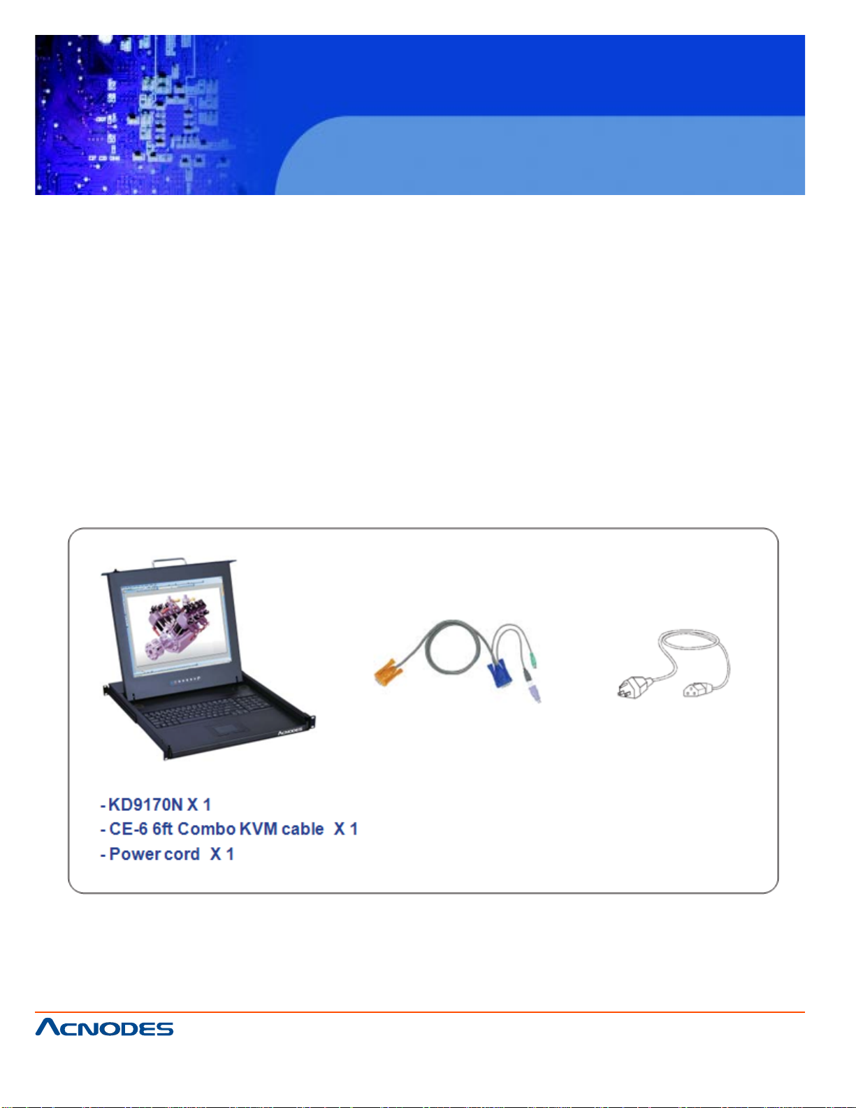
1.1 Package Contents P.1
1.2 Structure Diagram & Dimension P.2
1.3 Installation P.3-5
1.4 Connection to External KVM Switch or Server P.6
1.5 On-screen Display Operation ( OSD ) P.7
1.6 LCD / Keyboard / Mouse Specification P.8-9
1.7 Audio P.10
Package Content
661 Brea Canyon Rd., Suite 3
Walnut, CA 91789
tel: 909.598.7388, fax: 909.598.0218
© Copyright 2005 Acnodes, Inc.
All rights reserved. Product description and product specifications
are subject to change without notice. For latest product information,
please visit Acnodes’ web site at www.acnodes.com.
Page 5
KD 9170N
17” Short Depth Monitor Keyboard
Drawer
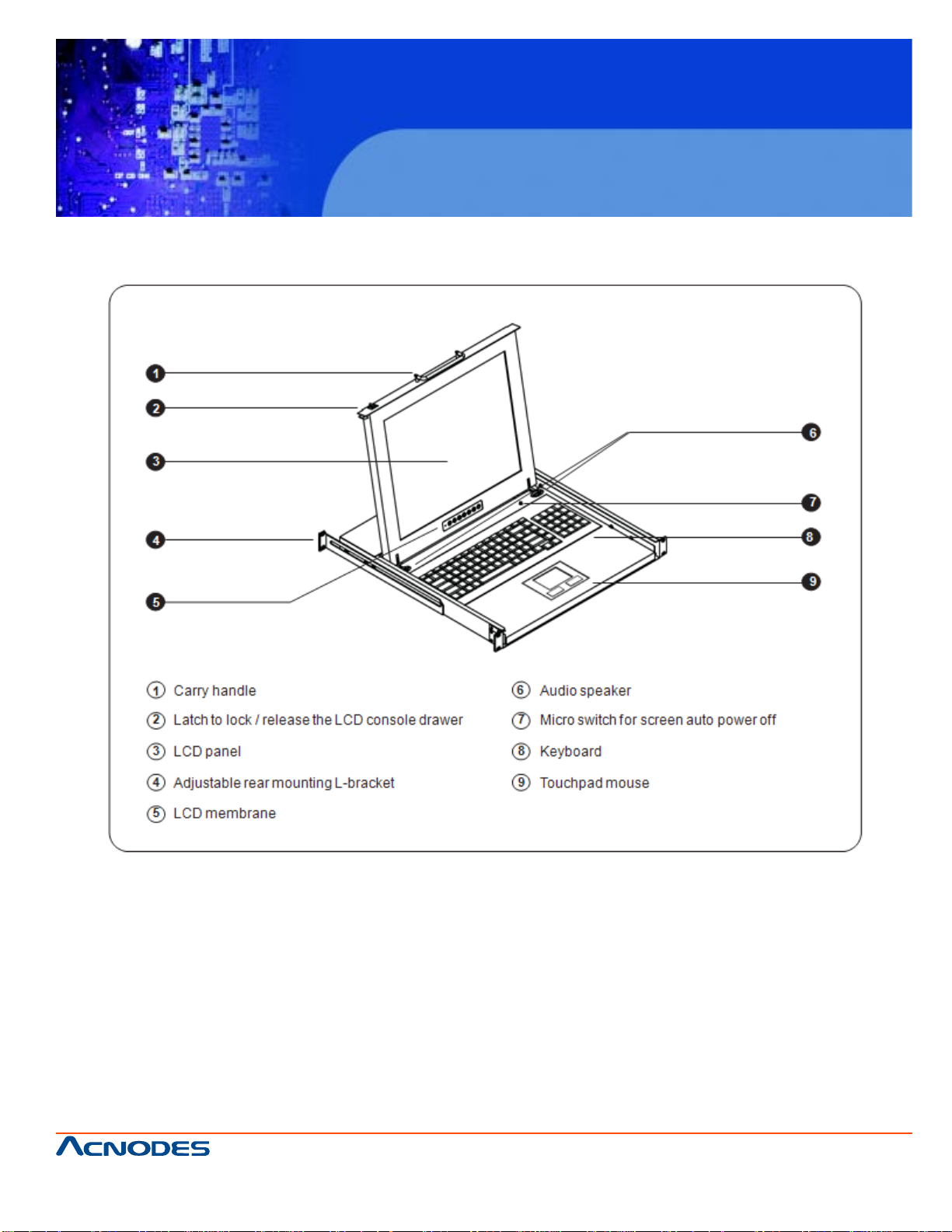
Structure Diagram & Dimension
661 Brea Canyon Rd., Suite 3
Walnut, CA 91789
tel: 909.598.7388, fax: 909.598.0218
© Copyright 2009 Acnodes, Inc.
All rights reserved. Product description and product specifications
are subject to change without notice. For latest product information,
please visit Acnodes’ web site at www.acnodes.com.
Page 6

KD 9170N
17” Short Depth Monitor Keyboard
Drawer
4.8 PCIE EXP ANSION CARD INST ALLA TION (OPTIONAL) ................................................ 51
4.9 A T/ATX MODE SELECTION ............................................................................................. 53
4.10 ACTIVATING THE FRONT USB CONNECTORS (WIDS SERIES ONL Y) .................... 53
4.1 1 MOUNTING THE SYSTEM ............................................................................................... 55
4.1 1.1 WALL MOUNTING .............................................................................................. 55
CHAPTER 5 BIOS SETUP
5.1 INTRODUCTION.................................................................................................................. 67
5.1.1 Starting Setup ...................................................................................................... 67
5.1.2 Using Setup .......................................................................................................... 67
5.1.3 Getting Help .......................................................................................................... 68
5.1.4 Unable to Reboot after Configuration Changes ................................................. 68
5.1.5 BIOS Menu Bar .................................................................................................... 68
5.2 MAIN.................................................................................................................................... 69
5.3 ADV ANCED ...................................................................................................................... 70
5.3.1 CPU Configuration .............................................................................................. 71
5.3.2 IDE Configuration ................................................................................................ 72
5.3.2.1 IDE Master , IDE Slave .......................................................................... 74
5.3.3 Super IO Configuration ....................................................................................... 77
5.3.4 Hardware Health Configuration .......................................................................... 83
5.3.5 Power Configuration ........................................................................................... 86
5.3.5.1 ACPI Settings......................................................................................... 87
5.3.5.2 APM Configuration................................................................................. 87
5.3.6 Remote Access Configuration ........................................................................... 90
5.3.7 USB Configuration............................................................................................... 93
5.4 PCI/PNP .................................................................................................................... .......... 95
5.5 BOOT ................................................................................................................................... 97
. 5.5.1 Boot Settings Configuration................................................................................. 98
661 Brea Canyon Rd., Suite 3
Walnut, CA 91789
tel: 909.598.7388, fax: 909.598.0218
© Copyright 2005 Acnodes, Inc.
All rights reserved. Product description and product specifications
are subject to change without notice. For latest product information,
please visit Acnodes’ web site at www.acnodes.com.
Page 7

KD 9170N
17” Short Depth Monitor Keyboard
Drawer
5.6 SECURITY ...................................................................................................................... 100
5.7 CHIPSET ........................................................................................................................ 101
5.7.1 North Bridge Configuration.............................................................................. 102
5.7.1.1 Video Function Configuration ........................................................... 103
5.7.2 South Bridge Configuration ............................................................................ 104
5.8 EXIT ................................................................................................................................ 105
CHAPTER 6 SYSTEM MAINTENANCE
6.1 SYSTEM MAINTENANCE INTRODUCTION ................................................................ 108
6.2 MOTHERBOARD REPLACEMENT ............................................................................. 108
6.3 BACK COVER REMOV AL ............................................................................................ 108
6.4 DIMM REPLACEMENT ................................................................................................. 109
6.5 ELEV A TED PLA TFORM REMOVAL .............................................................................110
6.6 PSU MODULE REPLACEMENT ...................................................................................1 12
6.6.1 Remove the Old PSU.........................................................................................1 12
6.6.2 Install the New PSU ...........................................................................................1 14
6.7 SYSTEM COOLING F AN REPLACEMENT ....................................................................115
6.7.1 Remove the Old System Cooling Fans ............................................................1 15
6.7.2 Install the New System Cooling Fans ...............................................................1 16
A. BIOS OPTIONS
B. DIGITAL I/O INTERFACE
B.1 INTRODUCTION ............................................................................................................ 126
B.2 DIO CONNECTOR PINOUTS ....................................................................................... 126
B.3 ASSEMBLY LANGUAGE SAMPLES ........................................................................... 127
B.3.1 Enable the DIO Input Function..................................................................................... 127
B.3.2 Enable the DIO Output Function ................................................................................. 127
C. WATCHDOG TIMER
661 Brea Canyon Rd., Suite 3
Walnut, CA 91789
tel: 909.598.7388, fax: 909.598.0218
© Copyright 2009 Acnodes, Inc.
All rights reserved. Product description and product specifications
are subject to change without notice. For latest product information,
please visit Acnodes’ web site at www.acnodes.com.
Page 8

KD 9170N
17” Short Depth Monitor Keyboard
Drawer
D. HAZARDOUS MATERIALS DISCLOSURE
D.1 HAZARDOUS MA TERIALS DISCLOSURE TABLE FOR IPB PRODUCTS CERTIFIED AS
ROHS COMPLIANT UNDER 2002/95/EC WITHOUT MERCURY ......................................152
661 Brea Canyon Rd., Suite 3
Walnut, CA 91789
tel: 909.598.7388, fax: 909.598.0218
© Copyright 2005 Acnodes, Inc.
All rights reserved. Product description and product specifications
are subject to change without notice. For latest product information,
please visit Acnodes’ web site at www.acnodes.com.
Page 9
KD 9170N
17” Short Depth Monitor Keyboard
Drawer
CHAPTER 1 INTRODUCTION
1. 1 OVERVIEW
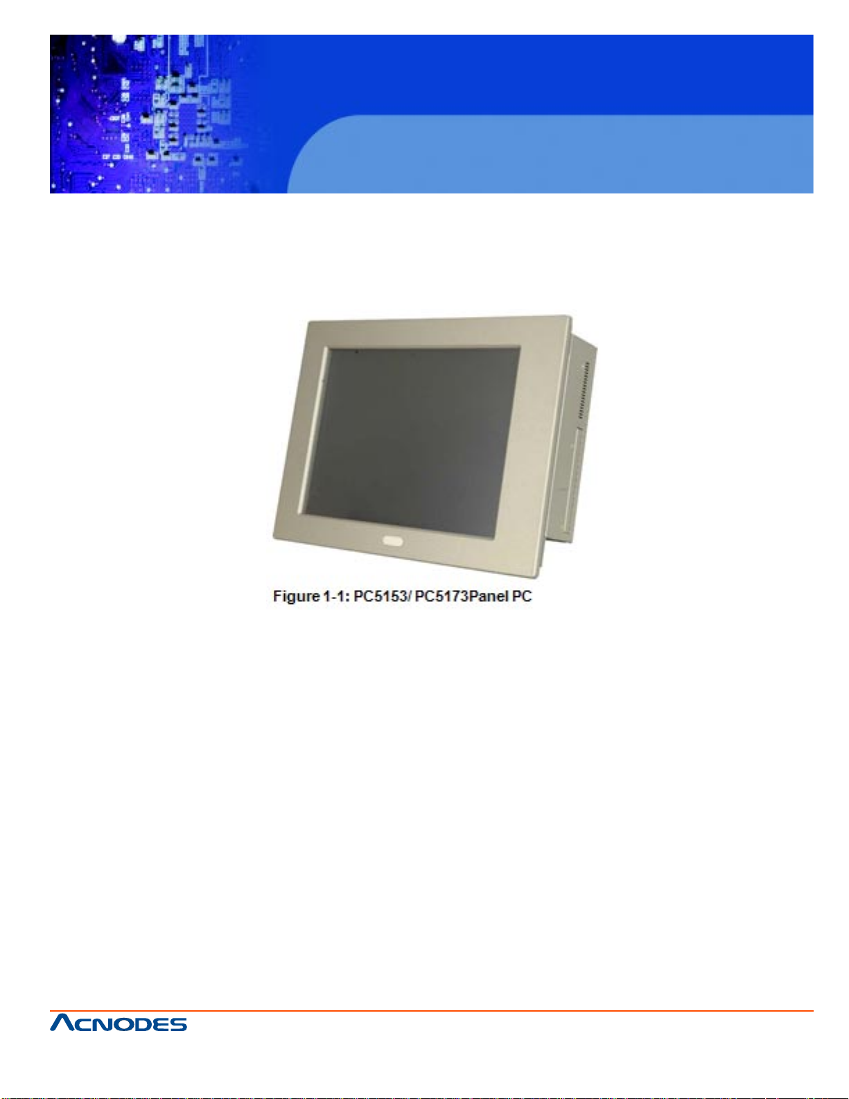
The PC5153/ PC5173 flat panel PC is for industrial environments like production lines and machine automation. The PC5153/ PC5173 provides all the features of a PC, combined with a touch
panel screen for mouse and keyboard free data input. The PC5153/ PC5173 provides wired
networking for integration into company networks and PC5153/ PC5173 also provides wireless
network via PIF A antenna on the front panel. All major external device connections including
USB, serial and parallel port connectors. Storage options include a
2.5" hard drive and a CompactFlash® slot, allowing for flexibility in choosing solid state drives or
traditional hard drives. A VGA output on the rear panel allows the PC5153/ PC5173 to connect
to a second screen for duplicating the screen contents or extending the user interface.
661 Brea Canyon Rd., Suite 3
Walnut, CA 91789
tel: 909.598.7388, fax: 909.598.0218
© Copyright 2009 Acnodes, Inc.
All rights reserved. Product description and product specifications
are subject to change without notice. For latest product information,
please visit Acnodes’ web site at www.acnodes.com.
Page 10

1.1.1 MODEL VARIATIONS
15” PC 5153
CPU: 2.2GHz Intel Celeron E1500
Power: AC input, 18~36V DC input
17” PC 5173
CPU: 2.2GHz Intel Celeron E1500
Power: AC input, 18~36V DC input
1.1.2 APPLICATIONS
KD 9170N
17” Short Depth Monitor Keyboard
Drawer
The PC5153/ PC5173 flat panel PC is designed for rigorous industrial environments where it may be
exposed to both heat and moisture. Its durability and strength also makes it an ideal choice for public
access computers. Some possible applications include:
ƒ Automated manufacturing processes
ƒ Public information gathering point
ƒ Plant environment monitoring system
ƒ Factory automation
ƒ Manufacturing shop flow
ƒ Equipment and device control
1.1.3 FEATURES
Some of the features of the PC5153/ PC5173 flat panel PC include:
ƒ Mainstream panel PC design with dual display function.
ƒ Aluminum die-casting front panel meet IP 65 water proof standard
ƒ Support LGA755 Intel® Core™2 Extreme/Quad/Duo, Celeron® processors with 800/1066/
1333 MHz FSB
661 Brea Canyon Rd., Suite 3
Walnut, CA 91789
tel: 909.598.7388, fax: 909.598.0218
© Copyright 2005 Acnodes, Inc.
All rights reserved. Product description and product specifications
are subject to change without notice. For latest product information,
please visit Acnodes’ web site at www.acnodes.com.
Page 11

KD 9170N
17” Short Depth Monitor Keyboard
Drawer
ƒ Dual DDR3 memory DIMM (system max. 4 GB SDRAM)
ƒ SA T A connectors
ƒ High brightness industrial grade LCD panel
ƒ The following I/O ports
o Five COM (one RS-232/422/485)
o One CompactFlash® slot
o One VGA port
o One Parallel port
o USB 2.0 ports
ƒ Dual 10/100/Gigabit Ethernet supported
ƒ RoHS compliant
1.2 EXTERNAL OVERVIEW
The PC5153/ PC5173 flat panel PC is comprised of an LCD screen, aluminum front panel and heavy
duty steel rear and side panels. The rear panel provides screw holes for wall and an arm mounting.
The right panel provides access to a slim type CD drive bay . The bottom p anel provides access to
external interface connectors that include GbE, USB 2.0, audio, parallel port, serial port connectors,
VGA port and a CompactFlash® card slot.
1.2.1 FRONT PANEL
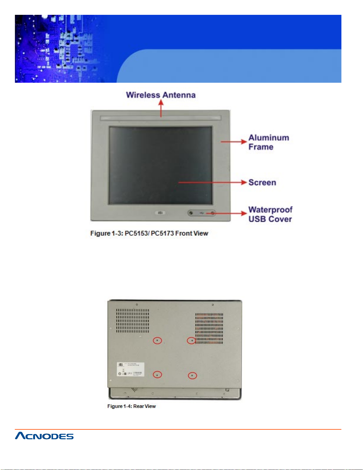
The front panel of the PC5153/ PC5173 (Figure 1-2) is a flat panel TFT LCD screen surrounded by an
aluminum frame. The PC5153/ PC5173 also has wireless antenna and two USB ports protected
by waterproof cover on the front panel.
661 Brea Canyon Rd., Suite 3
Walnut, CA 91789
tel: 909.598.7388, fax: 909.598.0218
© Copyright 2009 Acnodes, Inc.
All rights reserved. Product description and product specifications
are subject to change without notice. For latest product information,
please visit Acnodes’ web site at www.acnodes.com.
Page 12
KD 9170N
17” Short Depth Monitor Keyboard
Drawer
1.2.2REAR PANEL
The rear panel has a fan vent, four VESA standard mounting holes and several retention screw holes.
The VESA mounting holes are circled in Figure 1-4.
661 Brea Canyon Rd., Suite 3
Walnut, CA 91789
tel: 909.598.7388, fax: 909.598.0218
© Copyright 2005 Acnodes, Inc.
All rights reserved. Product description and product specifications
are subject to change without notice. For latest product information,
please visit Acnodes’ web site at www.acnodes.com.
Page 13
KD 9170N
17” Short Depth Monitor Keyboard
Drawer
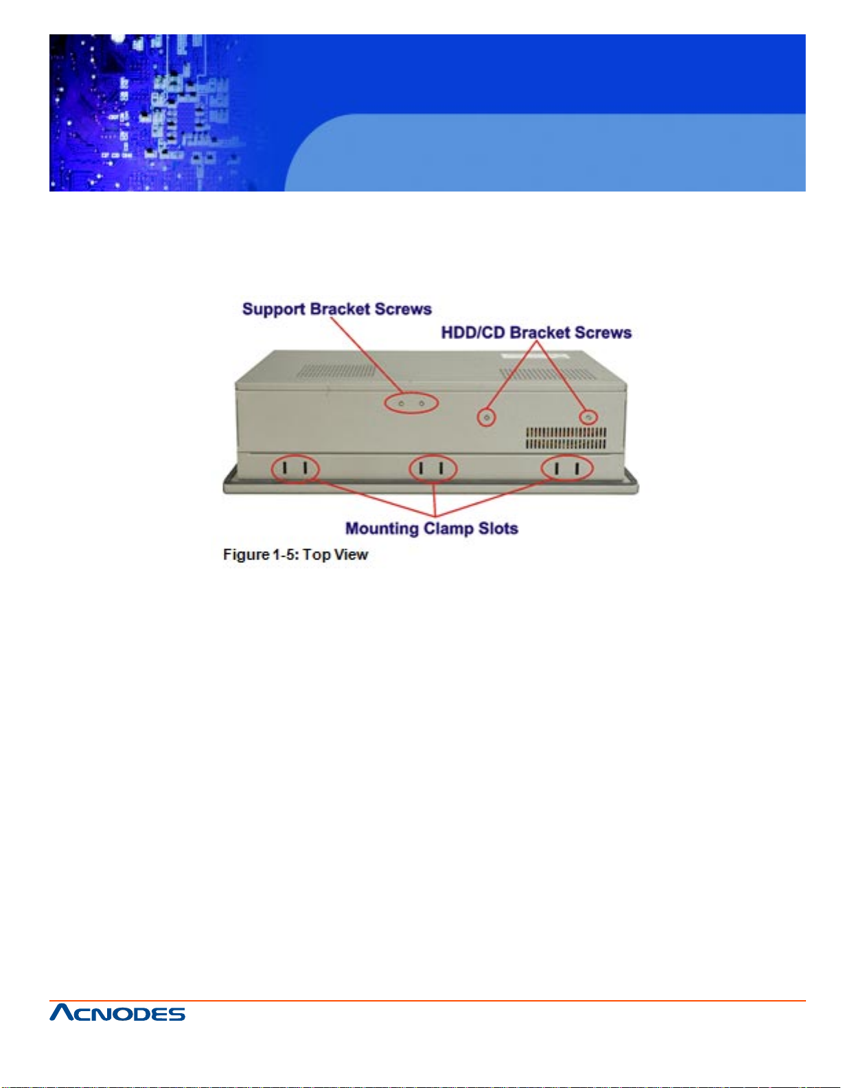
1.2.3 TOP PANEL
The top panel has three sets of mounting clamp slot, fan vents and retention screws for
securing the drive bay bracket. The retention screws are circled in Figure 1-5 below.
1.2.4 BOTTOM PANEL
The bottom panel shown in Figure 1-6 has the following interfaces:
ƒ 1 x Power input connector
ƒ 1 x Power switch
ƒ 4 x USB connectors
ƒ 1 x Reset button
ƒ 2 x RJ-45 GbE connectors
ƒ 1 x PS/2 mouse connector
ƒ 1 x PS/2 keyboard connector
ƒ 4 x RS-232 connectors (COM1, COM2, COM3 and COM4)
ƒ 1 x RS-232/422/485 connector (COM5)
ƒ 1 x PCI/PCIe x1 add-on card slot
ƒ 1 x Parallel port connector
661 Brea Canyon Rd., Suite 3
Walnut, CA 91789
tel: 909.598.7388, fax: 909.598.0218
© Copyright 2009 Acnodes, Inc.
All rights reserved. Product description and product specifications
are subject to change without notice. For latest product information,
please visit Acnodes’ web site at www.acnodes.com.
Page 14
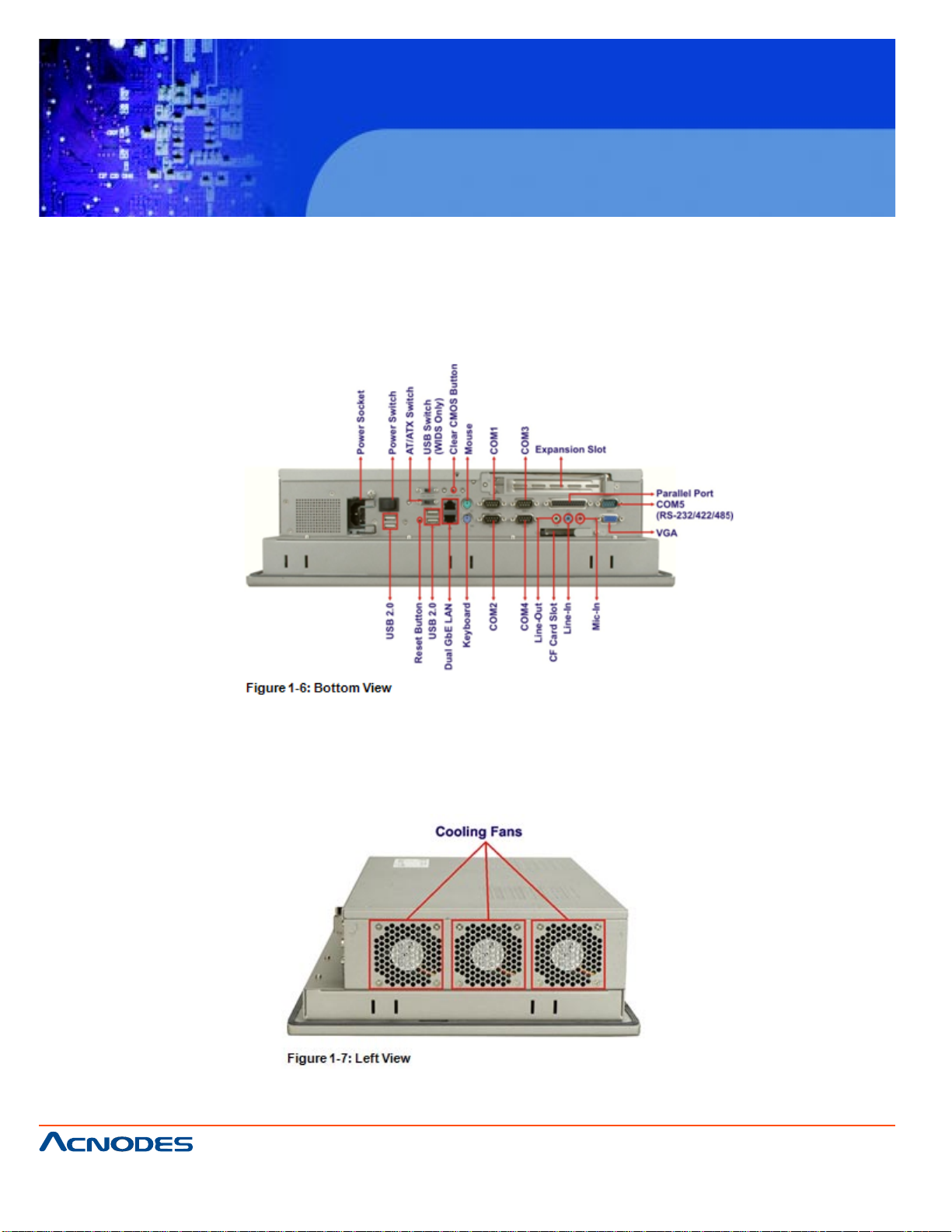
ƒ 3 x Audio jacks
ƒ 1 x VGA connector
ƒ 1 x CompactFlash® slot
ƒ 1 x AT/ATX switch
ƒ 1 x USB switch
KD 9170N
17” Short Depth Monitor Keyboard
Drawer
1.2.5 LEFT PANEL
The left side panel hosts three cooling fans that cool the interior of the system (Figure 1-7).
661 Brea Canyon Rd., Suite 3
Walnut, CA 91789
tel: 909.598.7388, fax: 909.598.0218
© Copyright 2005 Acnodes, Inc.
All rights reserved. Product description and product specifications
are subject to change without notice. For latest product information,
please visit Acnodes’ web site at www.acnodes.com.
Page 15
KD 9170N
17” Short Depth Monitor Keyboard
Drawer
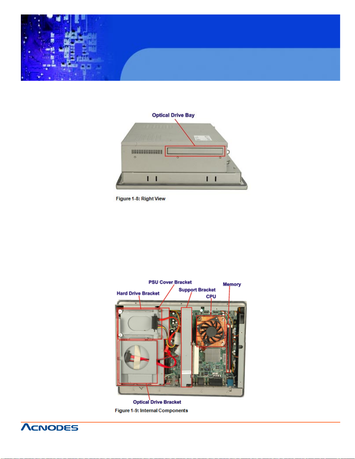
1.2.6 RIGHT PANEL
The right panel has a CD-ROM drive bay for CD-ROM drive installation (Figure 1-8).
1.3 INTERNAL OVERVIEW
The PC5153/ PC5173 internal components are configured in three levels. The PSU cover
bracket to the left (Figure 1-9) supports the hard drive and optical drive brackets. Below
the PSU cover bracket is the power supply. On the same level as the power supply is the
motherboard. Below the motherboard and PSU level is an LCD panel. An overview picture
of the internal components is shown in Figure 1-9 below.
661 Brea Canyon Rd., Suite 3
Walnut, CA 91789
tel: 909.598.7388, fax: 909.598.0218
© Copyright 2009 Acnodes, Inc.
All rights reserved. Product description and product specifications
are subject to change without notice. For latest product information,
please visit Acnodes’ web site at www.acnodes.com.
Page 16

KD 9170N
17” Short Depth Monitor Keyboard
Drawer
CHAPTER 2 SPECIFICA TIONS
2.1 INTRODUCTION
The PC5153/ PC5173 flat panel PC has the following preinstalled components:
ƒ 1 x Motherboard
ƒ 1 x TFT LCD screen
ƒ 1 x Power supply
ƒ 2 x Cooling fans
The technical specifications for these components and the system are shown in the sections
below.
2.1.1 SYSTEM SPECIFICATIONS
PC5153 PC5173
LCD Specs.Size 15" 17”
Resolution 1024 x 768 (XGA) 1280 x1024 (SXGA)
Brightness 350 cd/m2 380 cd/m2
Contrast Ratio 700:1 1000:1
Pixel Pitch (mm) 0.297 x 0.297 0.264 x 0.264
Viewing Angle (V-H) 125/140 160/ 170
LCD Color 16.2M 16.7M
Backlight MTBF 50,000 hours 50,000 hours
CPU:
2.66GHz Intel® Core™2 Quad Q9400 or 2.20GHz Intel® Celeron® dual-core E1500
CPU Socket: LGA775
Front Side Bus: 800 MHz, 1066 MHz or 1333 MHz
Northbridge Chipset: Intel® G41
Southbridge Chipset: Intel® ICH7
661 Brea Canyon Rd., Suite 3
Walnut, CA 91789
tel: 909.598.7388, fax: 909.598.0218
© Copyright 2005 Acnodes, Inc.
All rights reserved. Product description and product specifications
are subject to change without notice. For latest product information,
please visit Acnodes’ web site at www.acnodes.com.
Page 17

KD 9170N
17” Short Depth Monitor Keyboard
Drawer
Memory:
Two 2.0 GB 800/1066 MHz DDR3 SDRAM DIMM (system max. 4.0 GB)
Solid State Drive (SSD):
One CompactFlash® Type II socket
Drive Bay:
One 2.5" SATA 3Gb/s or IDE anti-shock drive bay,
One slim type CD-ROM bay
Ethernet: Two PCIe GbE controllers
Audio: RealTek ALC888 HD audio codec
I/O ports:
1 x RS-232/422/485 2 x LAN connectors
4 x RS-232 3 x Audio connectors (line-in, line-out and mic-in)
6 x USB 2.0 (two on front panel are waterproof) 1 x CMOS reset button
2 x PS/2 for keyboard and mouse 1 x AT/ATX switch
1 x Parallel port connector 1 x USB switch
1 x VGA-out connector 1 x Power switch
Wireless:
802.11 b/g/n wireless PCIe Mini module,
Wireless antenna embedded in front panel
Touch Screen: Resistive Type 5-wire (touch controller IC is on board)
Mounting: VESA 100 mm x 100 mm (panel, wall, rack, stand and arm)
661 Brea Canyon Rd., Suite 3
Walnut, CA 91789
tel: 909.598.7388, fax: 909.598.0218
© Copyright 2009 Acnodes, Inc.
All rights reserved. Product description and product specifications
are subject to change without notice. For latest product information,
please visit Acnodes’ web site at www.acnodes.com.
Page 18

KD 9170N
17” Short Depth Monitor Keyboard
Drawer
Expansion Slots:
Optional riser card: One PCI slot or One PCIe x4 with PCIe x1 signal
Chassis Construction: Heavy-duty steel
Front Panel Construction: Aluminum
Operating Temperature: -10ºC ~ 50ºC
Storage Temperature: -20ºC ~ 60ºC
Vibration: 5 Hz ~ 17 Hz 0.1" double amplitude displacement
17 Hz ~ 640 Hz 1.5G acceleration peak-to-peak
Shock: 10G acceleration peak-to-peak (11 ms)
Net/Gross Weight:
7 kg/11 kg 8 kg/12 kg
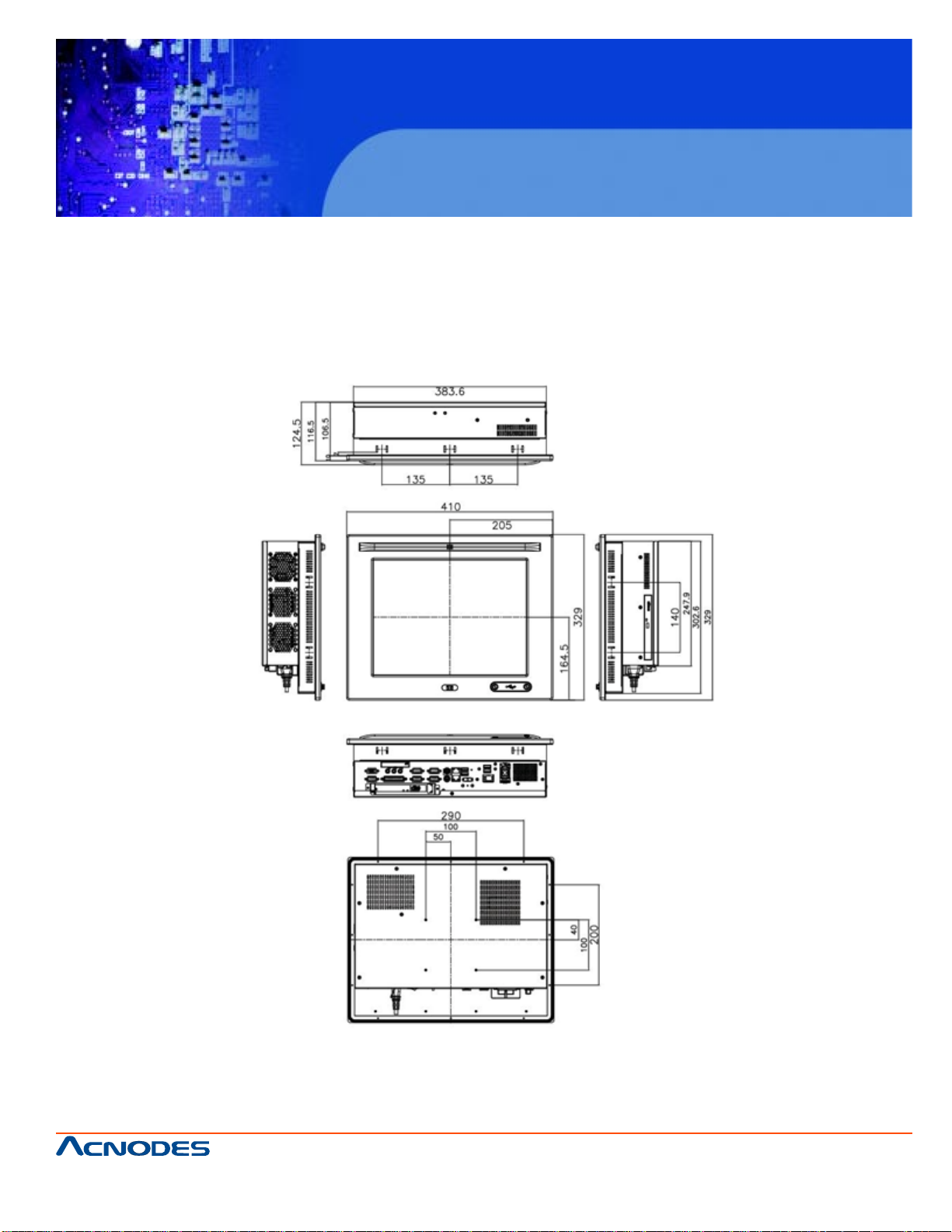
Dimensions (W x H x D):
410 x 309 x 110.5 452 x 356 x 115
Power Supply:
AC Input ATX (A Model)
ƒ 220 W
ƒ Input: 90 V AC~264 V AC, 50/60 Hz
ƒ Output(max.): 3.3 A@14 A, 5 V@16 A, 12 V@10 A, -12 V@0.8 A
DC Input ATX (AD Model)
ƒ 200 W
ƒ Input: 24 V DC (18~36 V DC), 50/60 Hz
ƒ -Output(max.): 3.3 A@12 A, 5 V@12 A, 12 V@15.4 A, -12 V@0.5 A
661 Brea Canyon Rd., Suite 3
Walnut, CA 91789
tel: 909.598.7388, fax: 909.598.0218
© Copyright 2005 Acnodes, Inc.
All rights reserved. Product description and product specifications
are subject to change without notice. For latest product information,
please visit Acnodes’ web site at www.acnodes.com.
Page 19
KD 9170N
17” Short Depth Monitor Keyboard
Drawer
2.2 DIMENSION
The dimensions of the PC5153/ PC5173 are shown in the sections below.
2.2.1 PC5153 DIMENSIONS
The dimensions of the PC5153 flat panel PC are shown below.
661 Brea Canyon Rd., Suite 3
Walnut, CA 91789
tel: 909.598.7388, fax: 909.598.0218
© Copyright 2009 Acnodes, Inc.
All rights reserved. Product description and product specifications
are subject to change without notice. For latest product information,
please visit Acnodes’ web site at www.acnodes.com.
Page 20
KD 9170N
17” Short Depth Monitor Keyboard
Drawer
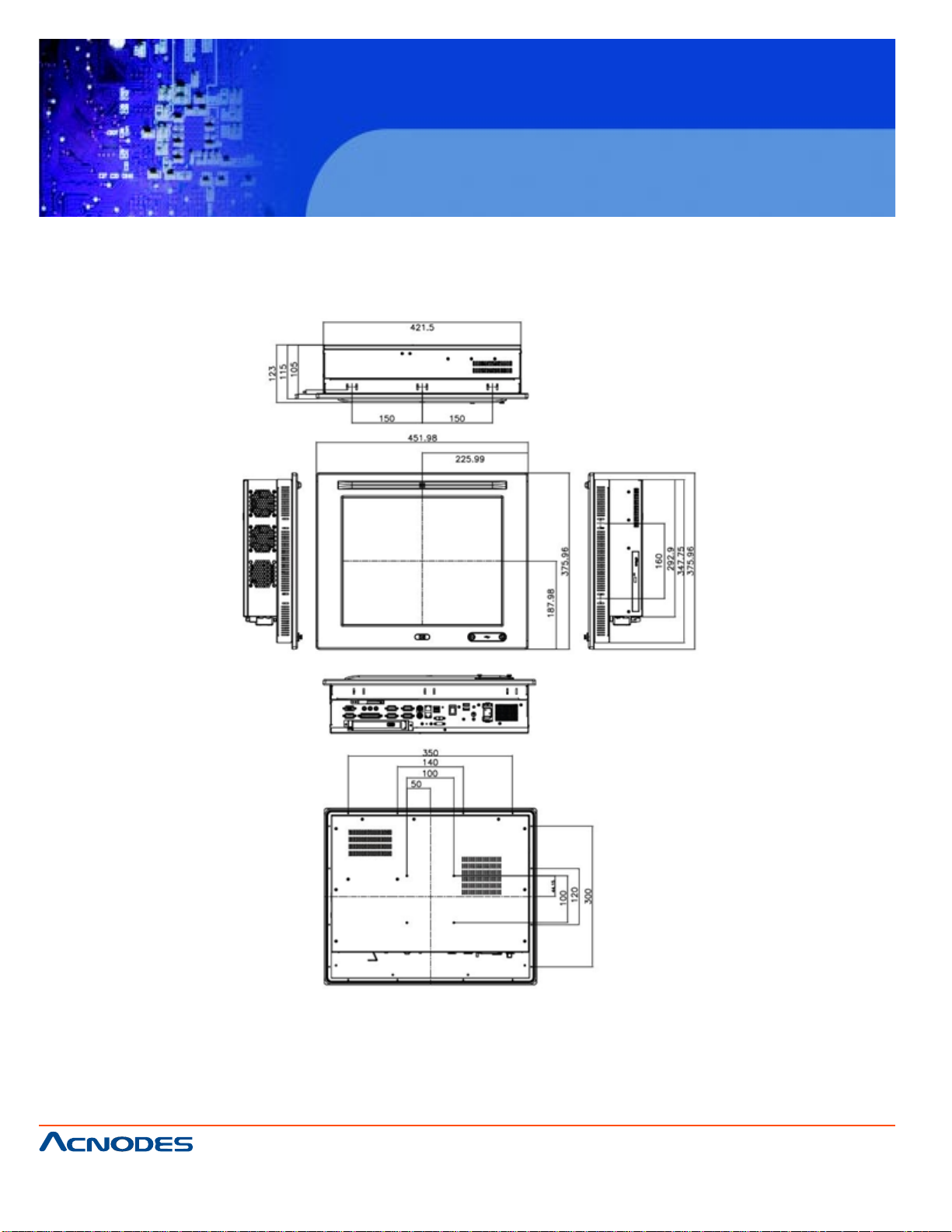
2.2.2 PC5173 DIMENSIONS
The dimensions of the PC5173 flat panel PC are shown below.
661 Brea Canyon Rd., Suite 3
Walnut, CA 91789
tel: 909.598.7388, fax: 909.598.0218
© Copyright 2005 Acnodes, Inc.
All rights reserved. Product description and product specifications
are subject to change without notice. For latest product information,
please visit Acnodes’ web site at www.acnodes.com.
Page 21
KD 9170N
17” Short Depth Monitor Keyboard
Drawer
2.3 GRAPHICS SUPPORT
The Intel® G41 chipset has an integrated graphics engine, Intel® Graphics
Media Accelerator X4500 that supports analog CRT display devices. The VGA port
on the external peripheral interface connector panel connects a peripheral
monitor to the PC5153/ PC5173 system.
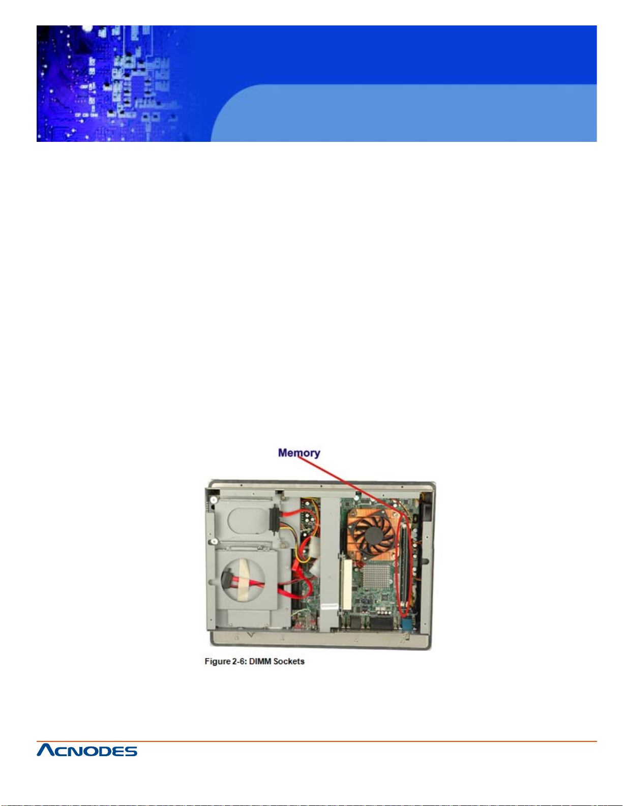
2.4 MEMORY
All processors supported by the PC5153/ PC5173 have their own internal DDR3
memory controller. The DDR3 controller has the following features:
ƒ Low-latency, high-bandwidth
ƒ Supports two 800 MHz, 1066 MHz or 1333 MHz DDR3 DIMMs
ƒ Each DIMM has a maximum capacity of 2.0 GB
The DDR3 controller on the processor is interfaced to two DIMM sockets on
the PC5153/ PC5173.
661 Brea Canyon Rd., Suite 3
Walnut, CA 91789
tel: 909.598.7388, fax: 909.598.0218
© Copyright 2009 Acnodes, Inc.
All rights reserved. Product description and product specifications
are subject to change without notice. For latest product information,
please visit Acnodes’ web site at www.acnodes.com.
Page 22
KD 9170N
17” Short Depth Monitor Keyboard
Drawer
2.5 STORAGE
There following storage options are available: CompactFlash® SATA hard drive
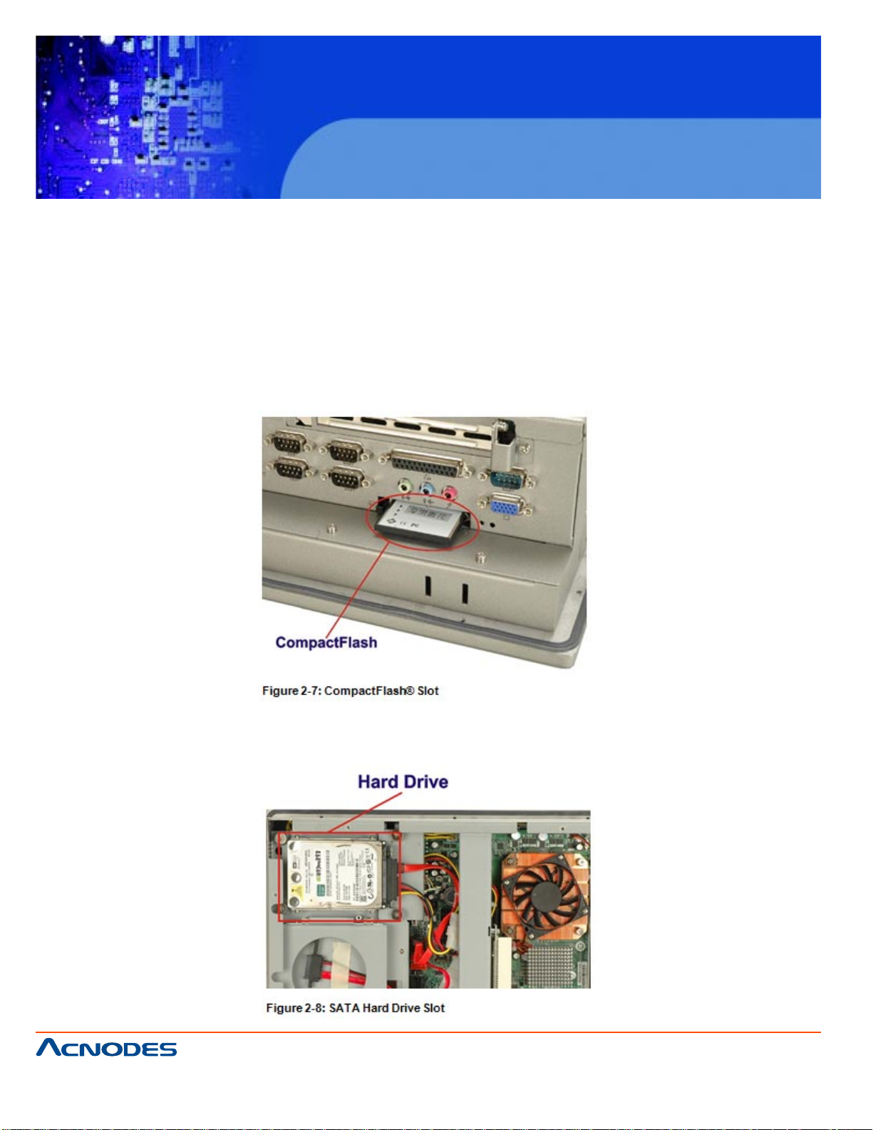
2.5.1 COMPACTFLASH
The CompactFlash® socket supports standard CompactFlash® Type II cards. The
chipset flash interface is multiplexed with an IDE interface and can be connected to an
array of industry standard NAND Flash or NOR Flash devices. The CompactFlash® slot
location is shown below.
2.5.2 HARD DRIVE
The PC5153/ PC5173 comes has a single drive bay for 2.5" SATA 3Gb/s hard drive or
IDE hard drive.
661 Brea Canyon Rd., Suite 3
Walnut, CA 91789
tel: 909.598.7388, fax: 909.598.0218
© Copyright 2005 Acnodes, Inc.
All rights reserved. Product description and product specifications
are subject to change without notice. For latest product information,
please visit Acnodes’ web site at www.acnodes.com.
Page 23

KD 9170N
17” Short Depth Monitor Keyboard
Drawer
2.6 FRONT PANEL
The front panel of the PC5153/ PC5173 consists of an LCD monitor and a touch
screen panel.
2.6.1 FLAT SCREEN
The PC5153/ PC5173 comes with a TFT LCD monitor. The tough construction of
the TFT monitor allows the PC5153/ PC5173 to withstand the conditions it is likely to be
exposed to during regular use. Some of the specifications of the TFT monitors are
shown below:
ƒ Pixel pitch of 0.297 mm or less
ƒ 700:1 contrast ratio or better
ƒ 350 cd/m2 or greater
ƒ 0oC to 50oC operating temperature
2.6.2 TOUCH SCREEN
The touch screen panel on the PC5153/ PC5173 allows complete user interaction without the need for a keyboard or mouse. Some of the features of the touch panel are
listed below.
ƒ 5-wire analog resistive type
ƒ 78% transmission
ƒ Control chipset built onto the motherboard
ƒ -10oC to 50oC operating temperature
ƒ 7 V maximum voltage
2.7 POWER SUPPLY
The PC5153/ PC5173 flat panel PC comes with either an AC input 220 W AC 1U, or
DC input 200 W DC 1U RoHS compliant ATX power supply. The PSUs have an MTBF
greater than 100,000 hours.
W ARNING:
Under no circumstances is the PSU case to be opened. The PSU module is not user
serviceable and there are dangerous high-voltages inside the case. If there are any
problems with the PSU module, please contact the dealer or reseller immediately.
661 Brea Canyon Rd., Suite 3
Walnut, CA 91789
tel: 909.598.7388, fax: 909.598.0218
© Copyright 2009 Acnodes, Inc.
All rights reserved. Product description and product specifications
are subject to change without notice. For latest product information,
please visit Acnodes’ web site at www.acnodes.com.
Page 24
KD 9170N
17” Short Depth Monitor Keyboard
Drawer
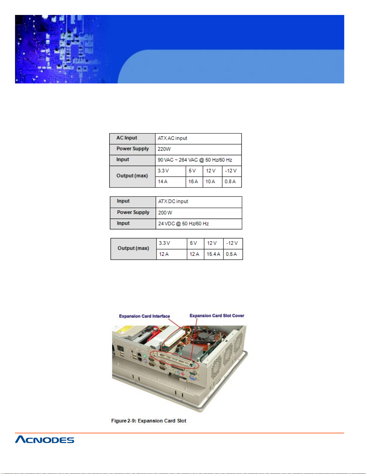
2.7.1.1 AC INPUT/ DC INPUT SPECIFICATIONS
There are three connector for two kinds of expansion modules, Type A module and
Type B module. Slot 1 and Slot 2 are for installing Type A module and Slot 3 is for Type
B module. The pinouts of these slots are listed below.
2.8 EXPANSION SLOTS
The riser card with either a PCI or PCIe x1 expansion card slot can be separately purchased and installed in the PC5153/ PC5173. The expansion card slots add additional
functionality to the PC5153/ PC5173.
661 Brea Canyon Rd., Suite 3
Walnut, CA 91789
tel: 909.598.7388, fax: 909.598.0218
© Copyright 2005 Acnodes, Inc.
All rights reserved. Product description and product specifications
are subject to change without notice. For latest product information,
please visit Acnodes’ web site at www.acnodes.com.
Page 25
KD 9170N
17” Short Depth Monitor Keyboard
Drawer
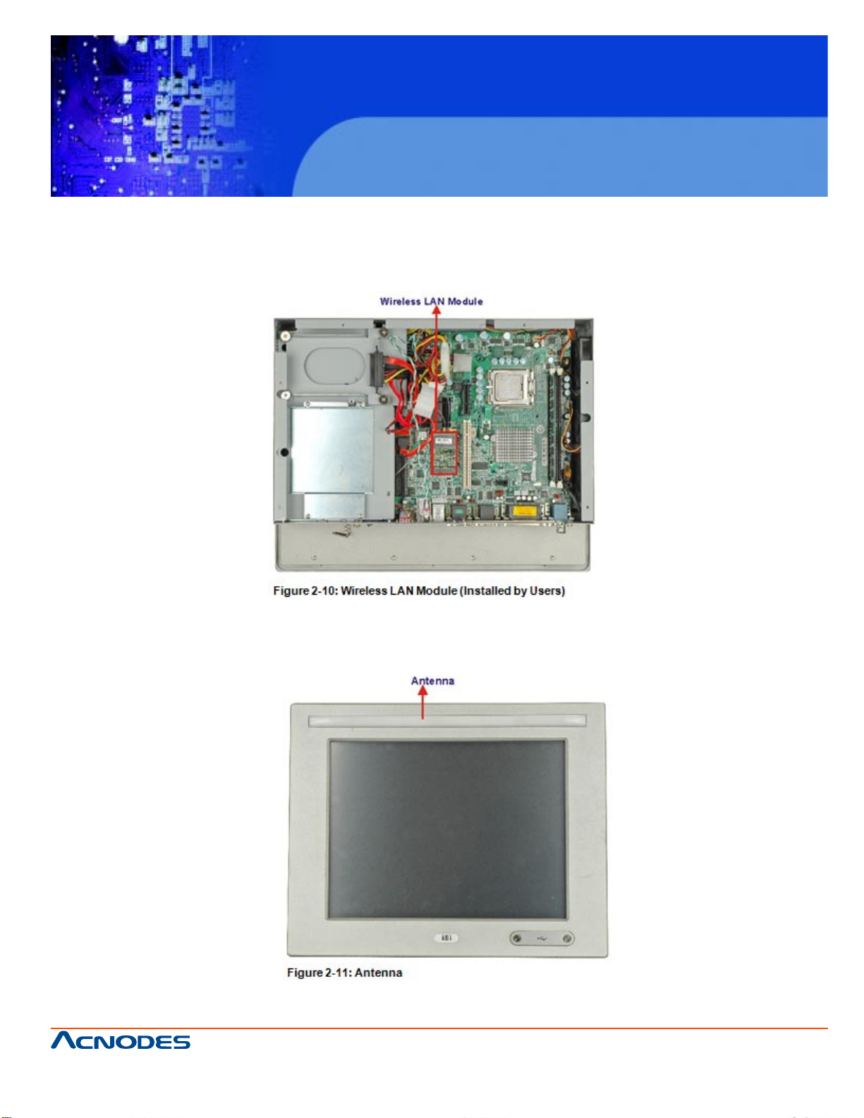
2.9 WIRELESS LAN
The PC5153/ PC5173 panel PC preinstalled an 802.11 b/g/n wireless LAN (WLAN)
module in the Mini-PCIe socket and interfaced to the Intel® ICH7 through the PCIe x1
bus.
The wireless module is then connected directly to the front panel PIFA antenna.
661 Brea Canyon Rd., Suite 3
Walnut, CA 91789
tel: 909.598.7388, fax: 909.598.0218
© Copyright 2009 Acnodes, Inc.
All rights reserved. Product description and product specifications
are subject to change without notice. For latest product information,
please visit Acnodes’ web site at www.acnodes.com.
Page 26

KD 9170N
17” Short Depth Monitor Keyboard
Drawer
CHAPTER 3 UNPACKING
3.1 ANTI-STATIC PRECAUTIONS
WARNING!
Failure to take ESD precautions during the installation of the PC5153/ PC5173
may result in permanent damage to the PC5153/ PC5173 and severe injury to the user.
Electrostatic discharge (ESD) can cause serious damage to electronic components, including the PC5153/ PC5173. Dry climates are especially susceptible to ESD.
It is critical that the following anti-static precautions are strictly adhered to whenever
handling the PC5153/ PC5173 or any other electrical component.
ƒ Wear an anti-static wristband - Wearing a simple anti-static wristband can help to
prevent ESD from damaging the PC5153/ PC5173.
ƒ Self-grounding - Touch a grounded conducting material before handling and peri
odically while handling the PC5153/ PC5173.
ƒ Use an anti-static pad - When configuring the PC5153/ PC5173, place it on an
antic-static pad to reduce the possibility of ESD damage.
ƒ Only handle the edges of the PC5153/ PC5173 - When handling the PC5153/
PC5173, hold it by its edges.
3.2 UNPACKING PRECAUTIONS
When the PC5153/ PC5173 is unpacked, please do the following:
ƒ Follow the anti-static precautions outlined in Section 3.1.
ƒ Make sure the packing box is facing upwards so the PC5153/ PC5173 does not
fall out of the box.
ƒ Make sure all the components shown in Section 3.3 are present.
3.3 PACKAGE CONTENTS
1 x PC5153/ PC5173
1 x SATA CD-ROM cable
1 x Panel Mount Kit
1 x Wall Mount Kit
1 x Power cord
1 x Screw set
661 Brea Canyon Rd., Suite 3
Walnut, CA 91789
tel: 909.598.7388, fax: 909.598.0218
© Copyright 2005 Acnodes, Inc.
All rights reserved. Product description and product specifications
are subject to change without notice. For latest product information,
please visit Acnodes’ web site at www.acnodes.com.
Page 27

KD 9170N
17” Short Depth Monitor Keyboard
Drawer
CHAPTER 4
INSTALLATION AND CONFIGURATION
4.1 INSTALLATION PRECAUTIONS
When installing the PC5153/ PC5173, please follow the precautions listed below:
ƒ Turn power off: When installing the PC5153/ PC5173 make sure the power is off.
Failing to turn off the power may cause severe injury to the body and/or damage
to the system.
ƒ Certified Engineers: Only certified engineers should install and modify on-board
functions.
ƒ Mounting: The PC5153/ PC5173 is a heavy device. When mounting the system
onto a rack, panel, wall or arm please make sure that at least two people are as
sisting with the procedure.
ƒ Anti-static Discharge: If a user open the rear panel of the PC5153/ PC5173, to
configure the jumpers or plug in added peripheral devices, ground themselves
first and wear and anti-static wristband.
4.2 PREINSTALLED COMPONENTS
The following components are all preinstalled.
ƒ Motherboard
ƒ TFT LCD
ƒ Touch screen
ƒ Power switch
ƒ Power supply
ƒ Inverter board
ƒ DIMM
ƒ System cooling fans
Preinstalled OEM customizations may include the following.
ƒ CPU
ƒ HDD
ƒ CD drive
ƒ PCI/PCIe x4 riser card
661 Brea Canyon Rd., Suite 3
Walnut, CA 91789
tel: 909.598.7388, fax: 909.598.0218
© Copyright 2009 Acnodes, Inc.
All rights reserved. Product description and product specifications
are subject to change without notice. For latest product information,
please visit Acnodes’ web site at www.acnodes.com.
Page 28
KD 9170N
17” Short Depth Monitor Keyboard
Drawer
Removal and reinstallation of some of the components are described in Chapter 4.
4.3 INSTALLATION AND CONFIGURATION STEPS
The following installation steps must be followed.
Step 1: Unpack the PC5153/ PC5173.
Step 2: Set the jumper settings.
Step 3: Install HDD, CompactFlash® and CD drive.
Step 4: Mount the PC5153/ PC5173 flat panel PC.
Step 5: Connect peripheral devices to the bottom panel of the PC5153/ PC5173.
Step 6: Configure the system.
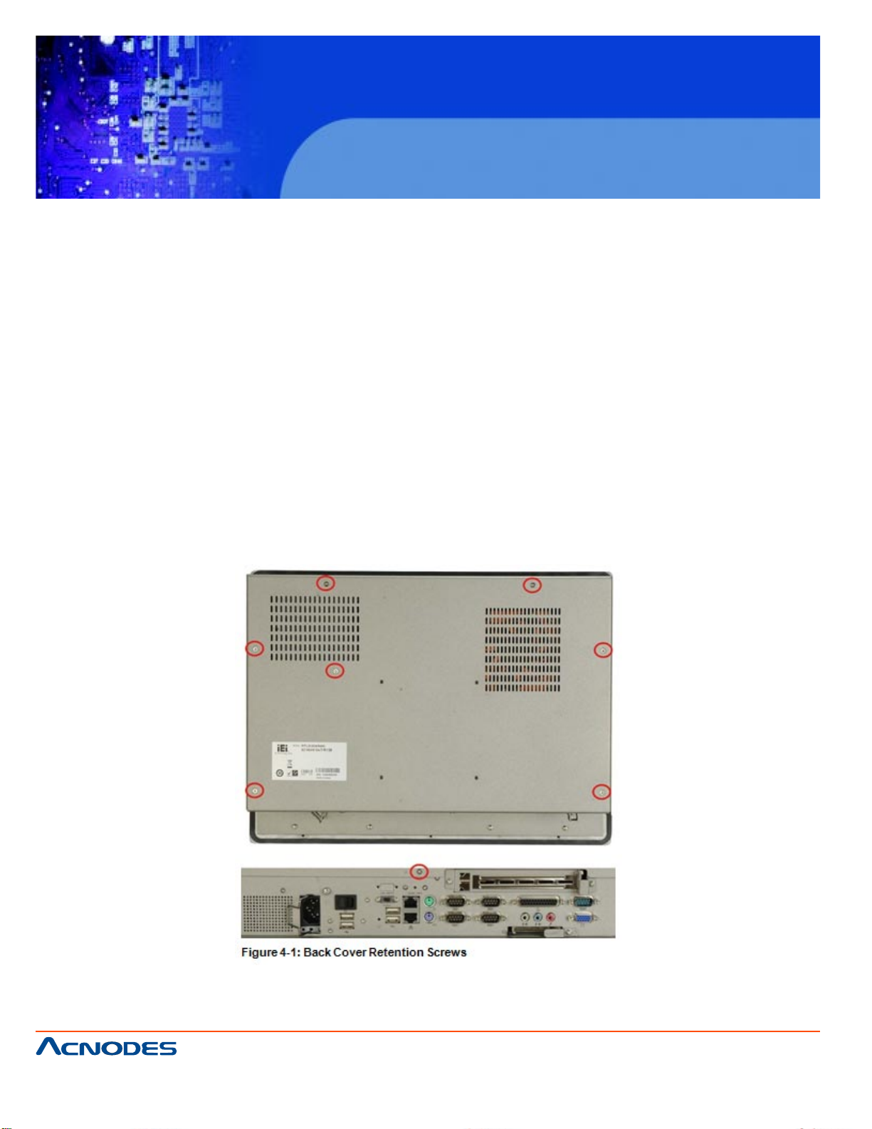
4.4 REMOVE THE BACK COVER
Remove all the retention screws on the back cover. Lift the cover up to remove
(Figure 4-1).
661 Brea Canyon Rd., Suite 3
Walnut, CA 91789
tel: 909.598.7388, fax: 909.598.0218
© Copyright 2005 Acnodes, Inc.
All rights reserved. Product description and product specifications
are subject to change without notice. For latest product information,
please visit Acnodes’ web site at www.acnodes.com.
Page 29
KD 9170N
17” Short Depth Monitor Keyboard
Drawer
4.5 JUMPER SETTINGS
NOTE:
A jumper is a metal bridge that is used to close an electrical circuit. It consists of two
metal pins and a small metal clip (often protected by a plastic cover that slides over
the pins to connect them. To CLOSE/SHORT a jumper means connecting the
pins of the jumper with the plastic clip and to OPEN a jumper means removing the plastic clip from a jumper.
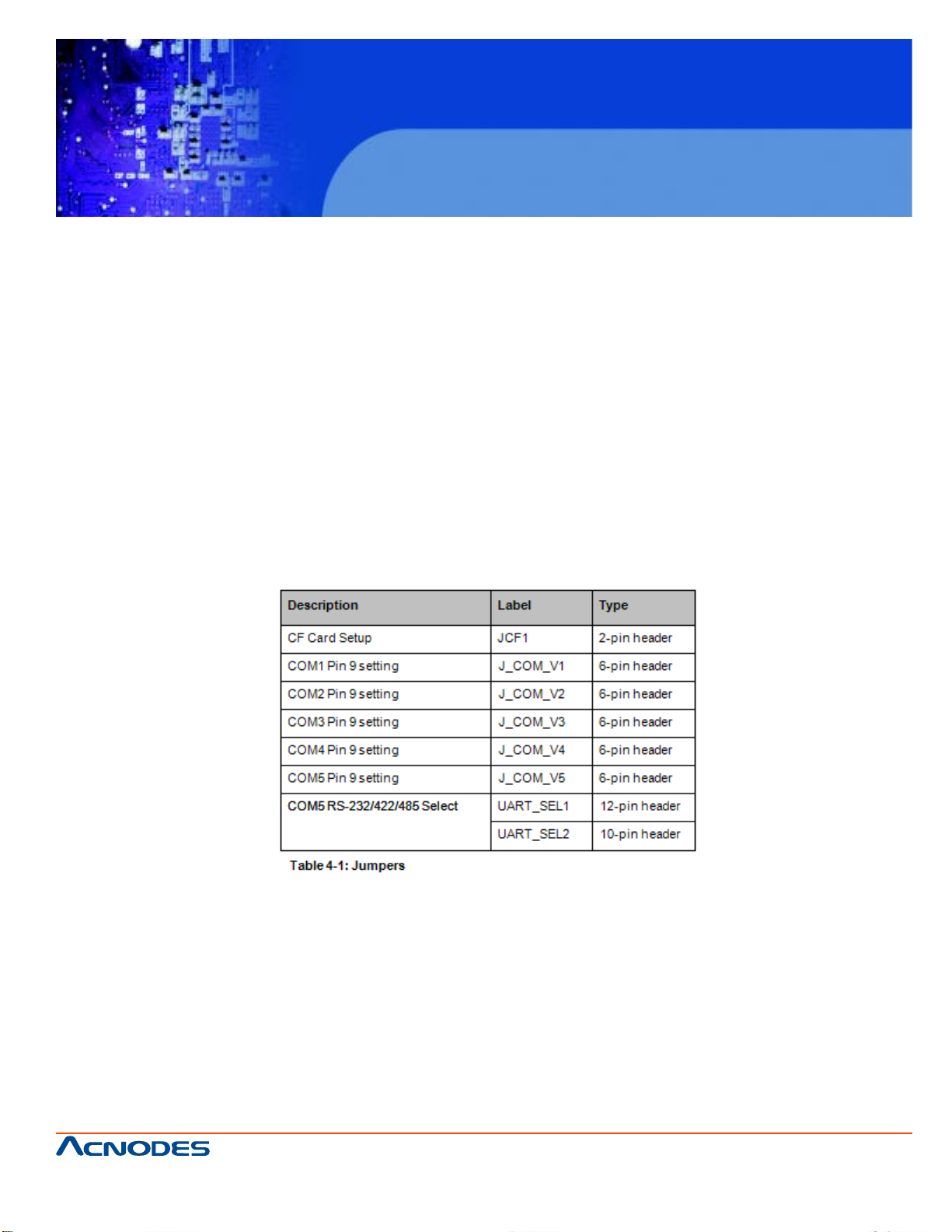
The following jumpers can be found on the motherboard installed in the PC5153/
PC5173. Before thePC5153/ PC5173 is installed, the jumpers must be set in accordance with the desired configuration. The jumpers on the PC5153/ PC5173
motherboard are listed in Table 4-1.
4.5.1 ACCESS THE JUMPER
To access the jumpers, remove the back panel. To remove the back panel, please refer
to Section 4.4.
661 Brea Canyon Rd., Suite 3
Walnut, CA 91789
tel: 909.598.7388, fax: 909.598.0218
© Copyright 2009 Acnodes, Inc.
All rights reserved. Product description and product specifications
are subject to change without notice. For latest product information,
please visit Acnodes’ web site at www.acnodes.com.
Page 30
KD 9170N
17” Short Depth Monitor Keyboard
Drawer
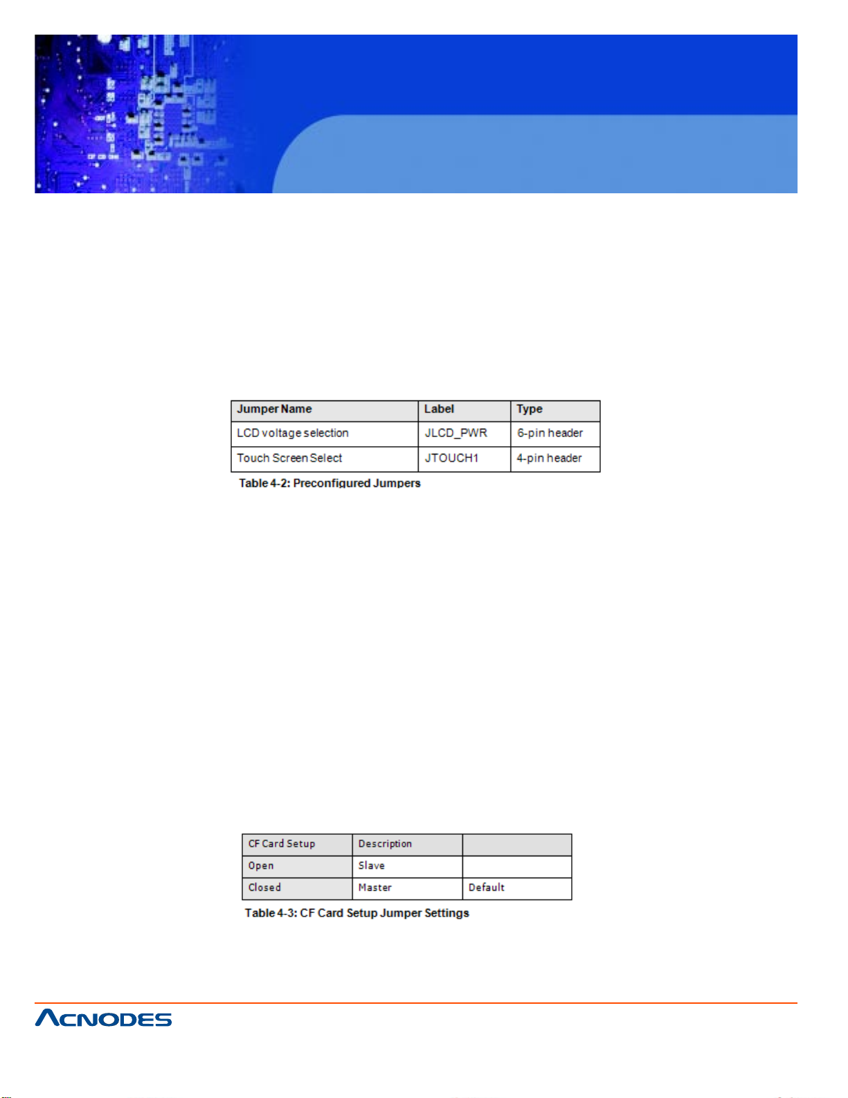
4.5.2 PRECONFIGURED JUMPERS
WARNING:
Do not change the settings on the jumpers in described here. Doing so may disable or
damage the system
The following jumpers are preconfigured for the PC5153/ PC5173. Users should no
change these jumpers.
4.5.3 CF CARD SETUP
Jumper Label: JCF1
Jumper Type: 2-pin header
Jumper Settings:See Table 4-3
Jumper Location: See Figure 4-2
The CF Card Setup jumper sets the CF Type I card or CF Type II cards as either the
slave device or the master device. CF Card Setup jumper settings are shown in Table
4-3.
The CF Card Setup jumper location is shown in Figure 4-2.
661 Brea Canyon Rd., Suite 3
Walnut, CA 91789
tel: 909.598.7388, fax: 909.598.0218
© Copyright 2005 Acnodes, Inc.
All rights reserved. Product description and product specifications
are subject to change without notice. For latest product information,
please visit Acnodes’ web site at www.acnodes.com.
Page 31

KD 9170N
17” Short Depth Monitor Keyboard
Drawer
4.5.4 COM1 TO COM5 PIN 9 SELECT
Jumper Label: J_COM_V1, J_COM_V2, J_COM_V3, J_COM_V4 and
J_COM_V5
Jumper Type: 6-pin header
Jumper Settings:See Table 4-4
Jumper Location: See Figure 4-3
Four jumpers configure pin 9 on the COM1, COM2, COM3 COM4 and COM5 connec-
tors. Pin 9 on these connectors can be set as either +5 V, +12 V or as the ring (RI)
signal. The COM1, COM2, COM3, COM4 and COM5 Pin 9 Setting jumper selection
options are shown in Table 4-4.
661 Brea Canyon Rd., Suite 3
Walnut, CA 91789
tel: 909.598.7388, fax: 909.598.0218
© Copyright 2009 Acnodes, Inc.
All rights reserved. Product description and product specifications
are subject to change without notice. For latest product information,
please visit Acnodes’ web site at www.acnodes.com.
Page 32

KD 9170N
17” Short Depth Monitor Keyboard
Drawer
The COM1 to COM5 Pin 9 Setting jumper locations are shown in Figure 4-3 below.
4.5.5 COM5 RS-232/422/485 SERIAL PORT SELECT JUMPER
Jumper Label: UART_SEL1 and UART_SEL2
Jumper Type: 12-pin header and 8-pin header
Jumper Settings:See Table 4-5
Jumper Location: See Figure 4-4
The COM5 RS-232/422/485 Serial Port Select jumper sets the communication protocol
used by the second serial communications port (COM5) as RS-232, RS-422 or RS-
485. The COM5 RS-232/422/485 Serial Port Select settings are shown in Table 4-5.
The COM5 RS-232/422/485 Serial Port Select jumper location is shown in Figure 4-4.
661 Brea Canyon Rd., Suite 3
Walnut, CA 91789
tel: 909.598.7388, fax: 909.598.0218
© Copyright 2005 Acnodes, Inc.
All rights reserved. Product description and product specifications
are subject to change without notice. For latest product information,
please visit Acnodes’ web site at www.acnodes.com.
Page 33

KD 9170N
17” Short Depth Monitor Keyboard
Drawer
4.5.5.1 COM5 RS-422 PINOUTS
The pinouts for RS-422 and RS-485 operation of external serial port COM 5 are detailed below.
4.6 DRIVE INSTALLATION
The drive installation process is shown in the sections below.
4.6.1 HARD DRIVE INSTALLATION
To install a HDD, please follow the steps below:
Step 1: Remove the back cover (Section 4.4).
Step 2: The HDD bracket is attached to the elevated platform by four retention screws.
Remove the four retention screws from the elevated platform (Figure 4-5).
661 Brea Canyon Rd., Suite 3
Walnut, CA 91789
tel: 909.598.7388, fax: 909.598.0218
© Copyright 2009 Acnodes, Inc.
All rights reserved. Product description and product specifications
are subject to change without notice. For latest product information,
please visit Acnodes’ web site at www.acnodes.com.
Page 34

KD 9170N
17” Short Depth Monitor Keyboard
Drawer
Step 3: Attach the SATA connector cable to the bracket.
Step 4: Attach the hard drive in the bracket. To do this, slide the hard drive onto the
bracket until it connects with the SATA connector at the back. Fasten the four retention
screws on the side.
661 Brea Canyon Rd., Suite 3
Walnut, CA 91789
tel: 909.598.7388, fax: 909.598.0218
© Copyright 2005 Acnodes, Inc.
All rights reserved. Product description and product specifications
are subject to change without notice. For latest product information,
please visit Acnodes’ web site at www.acnodes.com.
Page 35

KD 9170N
17” Short Depth Monitor Keyboard
Drawer
Step 5: Install the hard drive bracket (with hard drive and SATA cable attached) into the
PC5153/ PC5173 and fasten the four hard drive bracket screws.
661 Brea Canyon Rd., Suite 3
Walnut, CA 91789
tel: 909.598.7388, fax: 909.598.0218
© Copyright 2009 Acnodes, Inc.
All rights reserved. Product description and product specifications
are subject to change without notice. For latest product information,
please visit Acnodes’ web site at www.acnodes.com.
Page 36

KD 9170N
17” Short Depth Monitor Keyboard
Drawer
4.6.2 COMPACTFLASH INSTALLATION
To install the CompactFlash® card, please follow the steps below:
Step 1: Undo the CompactFlash® slot cover screw and remove the CompactFlash®
cover plate.
Step 2: Insert the CompactFlash® card into the slot.
Step 3: Fasten the CompactFlash® cover plate.
661 Brea Canyon Rd., Suite 3
Walnut, CA 91789
tel: 909.598.7388, fax: 909.598.0218
© Copyright 2005 Acnodes, Inc.
All rights reserved. Product description and product specifications
are subject to change without notice. For latest product information,
please visit Acnodes’ web site at www.acnodes.com.
Page 37

KD 9170N
17” Short Depth Monitor Keyboard
Drawer
4.6.3 CD DRIVE INSTALLATION
To install a CD drive, please follow the steps below.
Step 1: Remove the back cover (Section 4.4).
Step 2: Attach the CD drive adapter to the CD-ROM if it is an IDE drive (if it is a SATA
drive, proceed to Step 5:). Attach a CD drive adapter to a CD drive by aligning the two
retention screw holes in the CD drive adapter with the retention screw holes on the rear
side of the CD drive.
Step 3: Place two spacers between the CD drive and CD drive adapter.
Step 4: Insert two retention screws and secure the adapter to the CD drive
(Figure 4-12).
Step 5: Undo the optical drive bracket screws and remove the optical drive bracket.
661 Brea Canyon Rd., Suite 3
Walnut, CA 91789
tel: 909.598.7388, fax: 909.598.0218
© Copyright 2009 Acnodes, Inc.
All rights reserved. Product description and product specifications
are subject to change without notice. For latest product information,
please visit Acnodes’ web site at www.acnodes.com.
Page 38

KD 9170N
17” Short Depth Monitor Keyboard
Drawer
Step 6: Remove the four screws from the optical drive bracket assembly. Remove the
blank drive plate.
Step 7: Install the optical drive in the same position as the previously removed blank
optical drive plate. Fasten the same four screws to attach the optical drive to the
bracket.
661 Brea Canyon Rd., Suite 3
Walnut, CA 91789
tel: 909.598.7388, fax: 909.598.0218
© Copyright 2005 Acnodes, Inc.
All rights reserved. Product description and product specifications
are subject to change without notice. For latest product information,
please visit Acnodes’ web site at www.acnodes.com.
Page 39

KD 9170N
17” Short Depth Monitor Keyboard
Drawer
Step 8: Attach the SATA cable to the back of the optical drive and fasten the SATA
cable screws.
Step 9: Reinstall the optical drive bracket into the PC5153/ PC5173 and fasten the
optical bracket screws.
661 Brea Canyon Rd., Suite 3
Walnut, CA 91789
tel: 909.598.7388, fax: 909.598.0218
© Copyright 2009 Acnodes, Inc.
All rights reserved. Product description and product specifications
are subject to change without notice. For latest product information,
please visit Acnodes’ web site at www.acnodes.com.
Page 40

KD 9170N
17” Short Depth Monitor Keyboard
Drawer
4.7 PCI Expansion Card Installation (Optional)
To install a PCI expansion card, please do the following.
Step 1: Remove the back panel. See Section 4.4.
Step 2: Install the PCI riser card. Insert the PCI riser card into the PCI slot on the
motherboard of the system. Secure the PCI riser card to the system with two retention
screws.
661 Brea Canyon Rd., Suite 3
Walnut, CA 91789
tel: 909.598.7388, fax: 909.598.0218
© Copyright 2005 Acnodes, Inc.
All rights reserved. Product description and product specifications
are subject to change without notice. For latest product information,
please visit Acnodes’ web site at www.acnodes.com.
Page 41

KD 9170N
17” Short Depth Monitor Keyboard
Drawer
Step 3: Remove the expansion slot cover. The expansion slot on the I/O panel interface is secured to the system with a single retention screw. Remove the screw.
Step 4: Insert the expansion card. Align the PCI expansion card edge connector with
the PCI expansion slot on the PCI riser card. Gently insert the PCI card into the PCI
expansion slot.
Step 5: Secure the expansion card. Once the PCI card is correctly installed in the
system, reinsert the previously removed retention screw to secure the card to the I/O
interface panel.Step 0:
661 Brea Canyon Rd., Suite 3
Walnut, CA 91789
tel: 909.598.7388, fax: 909.598.0218
© Copyright 2009 Acnodes, Inc.
All rights reserved. Product description and product specifications
are subject to change without notice. For latest product information,
please visit Acnodes’ web site at www.acnodes.com.
Page 42

KD 9170N
17” Short Depth Monitor Keyboard
Drawer
4.8 PCIe Expansion Card Installation (Optional)
To install a PCI expansion card, please do the following.
Step 1: Remove the back panel. See Section 4.4.
Step 2: Install the PCIe riser card. Insert the PCIe riser card into the PCI slot and PCIe
x4 slot on the motherboard of the system. Secure the PCIe riser card to the system with
two retention screws.
Step 3: Remove the expansion slot cover. The expansion slot on the I/O panel interface is secured to the system with a single retention screw. Remove the screw.
661 Brea Canyon Rd., Suite 3
Walnut, CA 91789
tel: 909.598.7388, fax: 909.598.0218
© Copyright 2005 Acnodes, Inc.
All rights reserved. Product description and product specifications
are subject to change without notice. For latest product information,
please visit Acnodes’ web site at www.acnodes.com.
Page 43

KD 9170N
17” Short Depth Monitor Keyboard
Drawer
Step 4: Insert the expansion card. Align the PCIe expansion card edge connector with
the PCIe expansion slot on the PCIe riser card. Gently insert the PCIe card into the
PCIe expansion slot.
Step 5: Secure the expansion card. Once the PCIe card is correctly installed in the
system, reinsert the previously removed retention screw to secure the card to the I/O
interface panel.
4.9 AT/ATX Mode Selection
AT and ATX power modes can both be used on the PPC-51xxA-G41/WIDS-51xA-G41
flat panel PC. The selection is made through an AT/ATX switch on the I/O interface
panel. The switch is shown below.
661 Brea Canyon Rd., Suite 3
Walnut, CA 91789
tel: 909.598.7388, fax: 909.598.0218
© Copyright 2009 Acnodes, Inc.
All rights reserved. Product description and product specifications
are subject to change without notice. For latest product information,
please visit Acnodes’ web site at www.acnodes.com.
Page 44

KD 9170N
17” Short Depth Monitor Keyboard
Drawer
4.10 Activating the Front USB Connectors
A USB switch on the I/O panel of the PC5153/ PC5173 activates the two USB connectors on the front panel. To access the USB connectors and activate the connectors,
please do the following:
Step 1: Open the cover. The USB connectors are secured to the front panel of the
PC5153/ PC5173 with two retention screws. Remove these screws.
Step 2: Activate the USB connectors. To activate the USB connectors, move the USB
switch to the left.
661 Brea Canyon Rd., Suite 3
Walnut, CA 91789
tel: 909.598.7388, fax: 909.598.0218
© Copyright 2005 Acnodes, Inc.
All rights reserved. Product description and product specifications
are subject to change without notice. For latest product information,
please visit Acnodes’ web site at www.acnodes.com.
Page 45

KD 9170N
17” Short Depth Monitor Keyboard
Drawer
4.11 MOUNTING THE SYSTEM
WARNING!
When mounting the PC5153/ PC5173 flat panel PC onto an arm, wall or into a panel, it
is advisable to have more than one person help with the installation to prevent accidental damage to the panel and avoid personal injury.
The methods of mounting the PC5153/ PC5173 are:
ƒ Wall mounting
ƒ Panel mounting
ƒ Arm mounting
ƒ Rack mounting
The mounting methods are fully described below.
4.11.1 WALL MOUNTING
To mount the PC5153/ PC5173 flat panel PC onto a wall, please follow the steps below.
Step 1: Select the location on the wall for the wall-mounting bracket.
Step 2: Carefully mark the locations of the four bracket screw holes on the wall.
Step 3: Drill four pilot holes at the marked locations on the wall for the bracket retention
screws.
661 Brea Canyon Rd., Suite 3
Walnut, CA 91789
tel: 909.598.7388, fax: 909.598.0218
© Copyright 2009 Acnodes, Inc.
All rights reserved. Product description and product specifications
are subject to change without notice. For latest product information,
please visit Acnodes’ web site at www.acnodes.com.
Page 46

KD 9170N
17” Short Depth Monitor Keyboard
Drawer
Step 4: Align the wall-mounting bracket screw holes with the pilot holes.
Step 5: Secure the mounting-bracket to the wall by inserting the retention screws into
the four pilot holes and tightening them (see Figure 3-11).
Step 6: Insert the four monitor mounting screws provided in the wall mounting kit into
the four screw holes on the real panel of the monitor and tighten until the screw shank is
secured against the rear panel (see Figure 3-12).
Step 7: Align the mounting screws on the monitor rear panel with the mounting holes
on the bracket.
Step 8: Carefully insert the screws through the holes and gently pull the monitor downwards until the monitor rests securely in the slotted holes (see Figure 3-12). Ensure that
all four of the mounting screws fit snuggly into their respective slotted holes.
NOTE:
In the diagram below the bracket is already installed on the wall.
661 Brea Canyon Rd., Suite 3
Walnut, CA 91789
tel: 909.598.7388, fax: 909.598.0218
© Copyright 2005 Acnodes, Inc.
All rights reserved. Product description and product specifications
are subject to change without notice. For latest product information,
please visit Acnodes’ web site at www.acnodes.com.
Page 47

KD 9170N
17” Short Depth Monitor Keyboard
Drawer
Step 9: Secure the panel PC with the wall-mounting kit. To do this, stick the protective
cushion to the wall-mounting kit first. Then, put the wall-mounting kit on the top panel of
the panel PC. Carefully mark the location of the wall-mounting kit screw holes on the
wall. Drill a pilot hole at the marked location on the wall. Secure the wall-mounting kit to
the wall by inserting a retention screw into the pilot hole on the wall (Figure 4-30). This
step is to avoid the panel PC being pushed apart from the wall-mounting bracket accidentally.
4.11.2 Panel/ Mounting
To mount the PC5153/ PC5173 flat panel PC into a panel, please follow the steps below.
NOTE:
The maximum panel thickness should be no more than 6 mm.
Step 1: Select the position on the panel to mount the PC5153/ PC5173.
Step 2: Cut out a section of the panel that corresponds to the rear panel dimensions of
the PC5153/ PC5173. The recommended cutout sizes are shown below (Figure 4-31,
Figure 4-32 and Figure 4-33).
661 Brea Canyon Rd., Suite 3
Walnut, CA 91789
tel: 909.598.7388, fax: 909.598.0218
© Copyright 2009 Acnodes, Inc.
All rights reserved. Product description and product specifications
are subject to change without notice. For latest product information,
please visit Acnodes’ web site at www.acnodes.com.
Page 48

KD 9170N
17” Short Depth Monitor Keyboard
Drawer
Step 3: Slide the PC5153/ PC5173 through the hole until the metal frame is flush
against the panel.
Step 4: Insert the panel mounting clamps into the pre-formed holes along the edges of
the PC5153/ PC5173, behind the metal frame (Figure 4-36). Refer to the mounting kit
packing list for the required number of mounting clamps.
661 Brea Canyon Rd., Suite 3
Walnut, CA 91789
tel: 909.598.7388, fax: 909.598.0218
© Copyright 2005 Acnodes, Inc.
All rights reserved. Product description and product specifications
are subject to change without notice. For latest product information,
please visit Acnodes’ web site at www.acnodes.com.
Page 49

KD 9170N
17” Short Depth Monitor Keyboard
Drawer
Step 5: Tighten the screws that pass through the panel mounting clamps until the plastic caps at the front of all the screws are firmly secured to the panel (Figure 4-37).
4.11.3 Rack and Cabinet Installation
To mount the PC5153/ PC5173 into a rack/cabinet, please follow the steps below.
Step 1: Secure the rack mounting bracket to two sides of the monitor using the supplied retention screws (Figure 3-17). Each bracket requires four screws.
Step 2: Secure the rack mounting bracket to the rack by inserting and tightening the
supplied mounting nuts and bolts (Figure 3-17). Each bracket requires three nuts and
bolts for installation.
661 Brea Canyon Rd., Suite 3
Walnut, CA 91789
tel: 909.598.7388, fax: 909.598.0218
© Copyright 2009 Acnodes, Inc.
All rights reserved. Product description and product specifications
are subject to change without notice. For latest product information,
please visit Acnodes’ web site at www.acnodes.com.
Page 50

KD 9170N
17” Short Depth Monitor Keyboard
Drawer
4.11.4 Arm Mounting
The PC5153/ PC5173 is VESA (Video Electronics Standards Association) compliant
and can be mounted on an arm with a 100 mm interface pad. To mount the PC5153/
PC5173 on an arm, please follow the steps below.
Step 1: The arm is a separately purchased item. Please correctly mount the arm onto
the surface it uses as a base. To do this, refer to the installation documentation that
came with the mounting arm.
NOTE:
When purchasing the arm please ensure that it is VESA compliant and that the arm has
a 100 mm interface pad. If the mounting arm is not VESA compliant, it cannot
be used to support the PC5153/ PC5173 flat panel PC.
Step 2: Once the mounting arm has been firmly attached to its surface, lift the
PC5153/ PC5173 flat panel PC onto the interface pad of the mounting arm.
Step 3: Align the retention screw holes on the mounting arm interface with those in the
PC5153/ PC5173 flat panel PC. ThePC5153/ PC5173 flat panel PC arm mount retention screw.
Step 4: Secure the PC5153/ PC5173 to the interface pad by inserting four retention
screws through the mounting arm interface pad and into the
PC5153/ PC5173 flat panel PC.
661 Brea Canyon Rd., Suite 3
Walnut, CA 91789
tel: 909.598.7388, fax: 909.598.0218
© Copyright 2005 Acnodes, Inc.
All rights reserved. Product description and product specifications
are subject to change without notice. For latest product information,
please visit Acnodes’ web site at www.acnodes.com.
Page 51

KD 9170N
17” Short Depth Monitor Keyboard
Drawer
CHAPTER 5 BIOS SETUP
5.1 Introduction
The BIOS is programmed onto the BIOS chip. The BIOS setup program allows
changes to certain system settings. This chapter outlines the options that can be
changed.
5.1.1 Starting Setup
The AMI BIOS is activated when the computer is turned on. The setup program can be
activated in one of two ways.
1. Press the DELETE key as soon as the system is turned on or
2. Press the DELETE key when the "Press Del to enter SETUP" message appears on
the screen. 0.
If the message disappears before the DELETE key is pressed, restart the computer
and try again.
5.1.2 Using Setup
Use the arrow keys to highlight items, press ENTER to select, use the PAGEUP and
PAGEDOWN keys to change entries, press F1 for help and press ESC to quit. Navigation keys are shown below.
661 Brea Canyon Rd., Suite 3
Walnut, CA 91789
tel: 909.598.7388, fax: 909.598.0218
© Copyright 2009 Acnodes, Inc.
All rights reserved. Product description and product specifications
are subject to change without notice. For latest product information,
please visit Acnodes’ web site at www.acnodes.com.
Page 52

KD 9170N
17” Short Depth Monitor Keyboard
Drawer
5.1.3 Getting Help
When F1 is pressed a small help window describing the appropriate keys to use and
the possible selections for the highlighted item appears. To exit the Help Window press
ESC or the F1 key again.
5.1.4 Unable to Reboot After Configuration Changes
If the computer cannot boot after changes to the system configuration is made, CMOS
defaults. Use the jumper described in Chapter 5.
5.1.5 Main BIOS Menu
The menu bar on top of the BIOS screen has the following main items:
Main Changes the basic system configuration.
Advanced Changes the advanced system settings.
PCIPnP Changes the advanced PCI/PnP Settings
Boot Changes the system boot configuration.
Security Sets User and Supervisor Passwords.
Chipset Changes the chipset settings.
Power Changes power management settings.
Exit Selects exit options and loads default settings
The following sections completely describe the configuration options found in the menu
items at the top of the BIOS screen and listed above.
661 Brea Canyon Rd., Suite 3
Walnut, CA 91789
tel: 909.598.7388, fax: 909.598.0218
© Copyright 2005 Acnodes, Inc.
All rights reserved. Product description and product specifications
are subject to change without notice. For latest product information,
please visit Acnodes’ web site at www.acnodes.com.
Page 53

KD 9170N
17” Short Depth Monitor Keyboard
Drawer
5.2 Main
The Main BIOS menu (BIOS Menu 1) appears when the BIOS Setup program is entered. The Main menu gives an overview of the basic system information.
System Overview
The System Overview lists a brief summary of different system components. The fields in System Overview
cannot be changed. The items shown in the system overview include:
-AMI BIOS: Displays auto-detected BIOS information
o Version: Current BIOS version
o Build Date: Date the current BIOS version was made
o ID: Installed BIOS ID
-Processor: Displays auto-detected CPU specifications
o T ype: Names the currently installed processor
o Speed: List s the processor speed
o Count: The number of CPUs on the motherboard
661 Brea Canyon Rd., Suite 3
Walnut, CA 91789
tel: 909.598.7388, fax: 909.598.0218
© Copyright 2009 Acnodes, Inc.
All rights reserved. Product description and product specifications
are subject to change without notice. For latest product information,
please visit Acnodes’ web site at www.acnodes.com.
Page 54

KD 9170N
17” Short Depth Monitor Keyboard
Drawer
-System Memory: Displays the auto-detected system memory .
o Size: Lists memory size
The System Overview field also has two user configurable fields:
System Time [xx:xx:xx]
Use the System Time option to set the system time. Manually enter the hours, minutes and seconds.
System Date [xx/xx/xx]
Use the System Date option to set the system date. Manually enter the day , month and year .
5.3 Advanced
Use the Advanced menu (BIOS Menu 2) to configure the CPU and peripheral devices through the following
sub-menus:
WARNING:
Setting the wrong values in the sections below may cause the system to malfunction. Make sure that the
settings made are compatible with the hardware.
CPU Configuration
IDE Configuration
SuperIO Configuration
Hardware Health Configuration
Power Configuration
Remote Access Configuration
USB Configuration
661 Brea Canyon Rd., Suite 3
Walnut, CA 91789
tel: 909.598.7388, fax: 909.598.0218
© Copyright 2005 Acnodes, Inc.
All rights reserved. Product description and product specifications
are subject to change without notice. For latest product information,
please visit Acnodes’ web site at www.acnodes.com.
Page 55

KD 9170N
17” Short Depth Monitor Keyboard
Drawer
5.3.1 CPU Configuration
Use the CPU Configuration menu (BIOS Menu 3) to view detailed CPU specifications and configure the
CPU.
661 Brea Canyon Rd., Suite 3
Walnut, CA 91789
tel: 909.598.7388, fax: 909.598.0218
© Copyright 2009 Acnodes, Inc.
All rights reserved. Product description and product specifications
are subject to change without notice. For latest product information,
please visit Acnodes’ web site at www.acnodes.com.
Page 56

KD 9170N
17” Short Depth Monitor Keyboard
Drawer
The CPU Configuration menu (BIOS Menu 3) lists the following CPU details:
Manufacturer: Lists the name of the CPU manufacturer
Brand String: List s the brand name of the CPU being used
Frequency: Lists the CPU processing speed
FSB Speed: List s the FSB speed
Cache L1: Lists the CPU L1 cache size
Cache L2: Lists the CPU L2 cache size
5.3.2 IDE Configuration
Use the IDE Configuration menu (BIOS Menu 4) to change and/or set the configuration of the IDE devices
installed in the system.
661 Brea Canyon Rd., Suite 3
Walnut, CA 91789
tel: 909.598.7388, fax: 909.598.0218
© Copyright 2005 Acnodes, Inc.
All rights reserved. Product description and product specifications
are subject to change without notice. For latest product information,
please visit Acnodes’ web site at www.acnodes.com.
Page 57

KD 9170N
17” Short Depth Monitor Keyboard
Drawer
A T A/IDE Configurations [Comp atible]
Use the A T A/IDE Configurations option to configure the A T A/IDE controller .
Disabled Disables the on-board A T A/IDE controller .
Compatible Configures the on-board ATA/IDE controller to be in compatible mode. In this
mode, a SA T A channel will replace one of the IDE channels. This mode sup
ports up to 4 storage devices.
Enhanced (DEFAUL T) Configures the on-board A T A/IDE controller to be in Enhanced mode.
In this mode, IDE channels and SA T A channels are sep arated. This
mode supports up to 6 storage devices. Some legacy OS do not
support this mode.
Configure SA TA as [IDE]
Use the Configure SA T A as option to configure SA T A devices as normal IDE devices.
IDE DEFAUL T Configures SA T A devices as normal IDE device.
RAID Configures SA T A devices as normal RAID device.
AHCI Configures SA T A devices as normal AHCI device.
Configure SA TA Channels [Before PATA]
Use the Configure SA T A Channels option to determine how SAT A channels and P A T A channels are
ordered.
Before PATA DEFAULT Puts SAT A channels before P A T A channels.
Behind P AT A Puts SATA channels behind PA T A channels.
661 Brea Canyon Rd., Suite 3
Walnut, CA 91789
tel: 909.598.7388, fax: 909.598.0218
© Copyright 2009 Acnodes, Inc.
All rights reserved. Product description and product specifications
are subject to change without notice. For latest product information,
please visit Acnodes’ web site at www.acnodes.com.
Page 58

KD 9170N
17” Short Depth Monitor Keyboard
Drawer
IDE Master and IDE Slave
When entering setup, BIOS auto detects the presence of IDE devices. BIOS displays the status of
the auto detected IDE devices. The following IDE devices are detected and are shown in the IDE Configuration menu:
Primary IDE Master Third IDE Master
Primary IDE Slave Third IDE Slave
Secondary IDE Master
Secondary IDE Slave
The IDE Configuration menu (BIOS Menu 4) allows changes to the configurations for the IDE devices
installed in the system. If an IDE device is detected, and one of the above listed four BIOS configuration
options are selected, the IDE configuration options shown in Section 5.3.2.1 appear.
5.3.2.1 IDE Master, IDE Slave
Use the IDE Master and IDE Slave configuration menu to view both primary and secondary IDE
device details and configure the IDE devices connected to the system.
661 Brea Canyon Rd., Suite 3
Walnut, CA 91789
tel: 909.598.7388, fax: 909.598.0218
© Copyright 2005 Acnodes, Inc.
All rights reserved. Product description and product specifications
are subject to change without notice. For latest product information,
please visit Acnodes’ web site at www.acnodes.com.
Page 59

KD 9170N
17” Short Depth Monitor Keyboard
Drawer
Auto-Detected Drive Parameters
The "grayed-out" items in the left frame are IDE disk drive parameters automatically detected from
the firmware of the selected IDE disk drive. The drive parameters are listed as follows:
-Device: Lists the device type (e.g. hard disk, CD-ROM etc.)
-Type: Indicates the type of devices a user can manually select
-Vendor: Lists the device manufacturer
-Size: List the storage capacity of the device.
-LBA Mode: Indicates whether the LBA (Logical Block Addressing) is a method of address
ing data on a disk drive is supported or not.
-Block Mode: Block mode boosts IDE drive performance by increasing the amount of data
transferred. Only 512 bytes of data can be transferred per interrupt if block mode is not used. Block
mode allows transfers of up to 64 KB per interrupt.
-PIO Mode: Indicates the PIO mode of the installed device.
-Async DMA: Indicates the highest Asynchronous DMA Mode that is supported.
-Ultra DMA: Indicates the highest Synchronous DMA Mode that is supported.
-S.M.A.R.T .: Indicates whether or not the Self-Monitoring Analysis and Reporting T echnology proto
col is supported.
-32Bit Data T ransfer: Enables 32-bit data transfer .
T ype [Auto]
Use the T ype BIOS option select the type of device the AMIBIOS attempt s to boot from after the Power-On
Self-T est (POST) is complete.
Not Installed
BIOS is prevented from searching for an IDE disk drive on the specified channel.
Auto DEFAULT
The BIOS auto detects the IDE disk drive type attached to the specified channel. This setting should
be used if an IDE hard disk drive is attached to the specified channel.
CD/DVD
The CD/DVD option specifies that an IDE CD-ROM drive is attached to the specified IDE channel. The
BIOS does not attempt to search for other types of IDE disk drives on the specified channel.
ARMD
This option specifies an A T API Removable MediaDevice. These include, but are not limited to:
ZIP
LS-120
LBA/Large Mode [Auto]
661 Brea Canyon Rd., Suite 3
Walnut, CA 91789
tel: 909.598.7388, fax: 909.598.0218
© Copyright 2009 Acnodes, Inc.
All rights reserved. Product description and product specifications
are subject to change without notice. For latest product information,
please visit Acnodes’ web site at www.acnodes.com.
Page 60

KD 9170N
17” Short Depth Monitor Keyboard
Drawer
Use the LBA/Large Mode option to disable or enable BIOS to auto detects LBA (Logical
Block Addressing). LBA is a method of addressing dat a on a disk drive. In LBA mode, the maximum
drive capacity is 137 GB.
Disabled BIOS is prevented from using the LBA mode control on the specified channel.
Auto DEFAULT BIOS auto detects the LBA mode control on the specified channel.
Block (Multi Sector Transfer) [Auto]
Use the Block (Multi Sector T ransfer) to disable or enable BIOS to auto detect if the device supports
multi-sector transfers.
Disabled
BIOS is prevented from using Multi-Sector Transfer on the specified channel. The data to and from the
device occurs one sector at a time.
Auto DEFAULT
BIOS auto detects Multi-Sector T ransfer support on the drive on the specified channel. If supported
the data transfer to and from the device occurs multiple sectors at a time.
PIO Mode [Auto]
Use the PIO Mode option to select the IDE PIO (Programmable I/O) mode program timing cycles
between the IDE drive and the programmable IDE controller . As the PIO mode increases, the cycle time
decreases.
Auto
DEFAULT
BIOS auto detects the PIO mode. Use this value if the IDE disk
drive support cannot be determined.
0
PIO mode 0 selected with a maximum transfer rate of 3.3MBps
1
PIO mode 1 selected with a maximum transfer rate of 5.2MBps
2
PIO mode 2 selected with a maximum transfer rate of 8.3MBps
3
PIO mode 3 selected with a maximum transfer rate of 1 1.1MBps
4
PIO mode 4 selected with a maximum transfer rate of 16.6MBps (This setting generally works with
all hard disk drives manufactured after 1999. For other disk drives, such as IDE CD-ROM drives,
check the specifications of the drive.)
661 Brea Canyon Rd., Suite 3
Walnut, CA 91789
tel: 909.598.7388, fax: 909.598.0218
© Copyright 2005 Acnodes, Inc.
All rights reserved. Product description and product specifications
are subject to change without notice. For latest product information,
please visit Acnodes’ web site at www.acnodes.com.
Page 61

KD 9170N
17” Short Depth Monitor Keyboard
Drawer
DMA Mode [Auto]
Use the DMA Mode BIOS selection to adjust the DMA mode options.
Auto DEFAULT
BIOS auto detects the DMA mode. Use this value if the IDE disk drive support cannot
be determined.
S.M.A.R.T [Auto]
Use the S.M.A.R.T option to auto-detect, disable or enable Self-Monitoring Analysis and
Reporting Technology (SMART) on the drive on the specified channel. S.M.A.R.T predicts impending drive failures. The S.M.A.R.T BIOS option enables or disables this
function.
Auto DEFAULT
BIOS auto detects HDD SMART support.
Disabled
Prevents BIOS from using the HDD SMART feature.
Enabled
Allows BIOS to use the HDD SMART feature
32Bit Data Transfer [Enabled]
Use the 32Bit Data Transfer BIOS option to enables or disable 32-bit data transfers.
Disabled
Prevents the BIOS from using 32-bit data transfers.
Enabled D EFAU LT
Allows BIOS to use 32-bit data transfers on supported hard disk drives.
661 Brea Canyon Rd., Suite 3
Walnut, CA 91789
tel: 909.598.7388, fax: 909.598.0218
© Copyright 2009 Acnodes, Inc.
All rights reserved. Product description and product specifications
are subject to change without notice. For latest product information,
please visit Acnodes’ web site at www.acnodes.com.
Page 62

KD 9170N
17” Short Depth Monitor Keyboard
Drawer
5.3.3 Super IO Configuration
Use the Super IO Configuration menu (BIOS Menu 6) to set or change the configurations for the FDD controllers, parallel ports and serial ports.
Parallel Port Address [Disabled]
Use the Parallel Port Address option to select the parallel port base address.
Disabled DE FAULT
No base address is assigned to the Parallel Port
378
Parallel Port I/O port address is 378
278
Parallel Port I/O port address is 278
3BC
Parallel Port I/O port address is 3BC
Parallel Port Mode [Normal]
Use the Parallel Port Mode option to select the mode the parallel port operates in.
661 Brea Canyon Rd., Suite 3
Walnut, CA 91789
tel: 909.598.7388, fax: 909.598.0218
© Copyright 2005 Acnodes, Inc.
All rights reserved. Product description and product specifications
are subject to change without notice. For latest product information,
please visit Acnodes’ web site at www.acnodes.com.
Page 63

KD 9170N
17” Short Depth Monitor Keyboard
Drawer
Normal DEFAULT
The normal parallel port mode is the standard mode for parallel port operation.
Bi-directional
Parallel port outputs are 8-bits long. Inputs are accomplished by reading 4 of the
8 bits on the status register.
EPP
The parallel port operates in the enhanced parallel port mode (EPP). The EPP
mode supports bi-directional communication between the system and the parallel
port device and the transmission rates between the two are much faster than the Normal
mode.
ECP+EPP
The parallel port operates inthe extended capabilities port (ECP) mode. The ECP
mode supports bi-directional communication between the system and the parallel
port device and the transmission rates between the two are much faster than the
Normal mode The parallel port is also be compatible with EPP devices described
above
Parallel Port IRQ [IRQ7]
Use the Parallel Port IRQ selection to set the parallel port interrupt address.
IRQ5 IRQ5 is assigned as the parallel port interrupt address
IRQ7 DEFAULT IRQ7 is assigned as the parallel port interrupt address
Serial Port1 Address [3F8/IRQ4]
Use the Serial Port1 Address option to select the Serial Port 1 base address.
Disabled
No base address is assigned to Serial Port 1
3F8/IRQ4 DEFAULT
Serial Port 1 I/O port address is 3F8 and the interrupt address is IRQ4
3E8/IRQ4
Serial Port 1 I/O port address is 3E8 and the interrupt address is IRQ4
2E8/IRQ3
Serial Port 1 I/O port address is 2E8 and the interrupt address is IRQ3
Serial Port1 Mode [Normal]
Use the Serial Port1 Mode option to select the transmitting and receiving mode for the
first serial port.
661 Brea Canyon Rd., Suite 3
Walnut, CA 91789
tel: 909.598.7388, fax: 909.598.0218
© Copyright 2009 Acnodes, Inc.
All rights reserved. Product description and product specifications
are subject to change without notice. For latest product information,
please visit Acnodes’ web site at www.acnodes.com.
Page 64

KD 9170N
17” Short Depth Monitor Keyboard
Drawer
Normal D E FAU LT Serial Port 1 mode is normal
IrDA Serial Port 1 mode is IrDA
ASK IR Serial Port 1 mode is ASK IR
Serial Port2 Address [2F8/IRQ3]
Use the Serial Port2 Address option to select the Serial Port 2 base address.
Disabled No base address is assigned to Serial Port 2
2F8/IRQ3 DEFAULT
Serial Port 2 I/O port address is 3F8 and the interrupt address is IRQ3
3E8/IRQ4 Serial Port 2 I/O port address is 3E8 and the interrupt
address is IRQ4
2E8/IRQ3 Serial Port 2 I/O port address is 2E8 and the interrupt
address is IRQ3
Serial Port2 Mode [Normal]
Use the Serial Port2 Mode option to select the Serial Port2 operational mode.
Normal D E FAU LT Serial Port 2 mode is normal
IrDA Serial Port 2 mode is IrDA
ASK IR Serial Port 2 mode is ASK IR
Serial Port3 Address [3E8]
Use the Serial Port3 Address option to select the base addresses for serial port 3.
Disabled No base address is assigned to serial port 3
3 E8 DE FAULT Serial port 3 I/O port address is 3E8
2 E8 Serial port 3 I/O port address is 2E8
2 F0 Serial port 3 I/O port address is 2F0
2 E0 Serial port 3 I/O port address is 2E0
Serial Port3 IRQ [11]
Use the Serial Port3 IRQ option to select the interrupt address for serial port 3.
1 0 Serial port 3 IRQ address is 10
11 D EFAULT Serial port 3 IRQ address is 11
661 Brea Canyon Rd., Suite 3
Walnut, CA 91789
tel: 909.598.7388, fax: 909.598.0218
© Copyright 2005 Acnodes, Inc.
All rights reserved. Product description and product specifications
are subject to change without notice. For latest product information,
please visit Acnodes’ web site at www.acnodes.com.
Page 65

KD 9170N
17” Short Depth Monitor Keyboard
Drawer
Serial Port4 Address [2E8]
Use the Serial Port4 IRQ option to select the interrupt address for serial port 4.
Disabled No base address is assigned to serial port 3
3F8
Serial Port 4 I/O port address is 3F8
2F8
Serial Port 4 I/O port address is 2F8
3E8
Serial Port 4 I/O port address is 3E8
2E8
DEFAULT Serial Port 4 I/O port address is 2E8
2E0
Serial Port 4 I/O port address is 2E0
Serial Port4 IRQ [10]
Use the Serial Port4 IRQ option to select the interrupt address for serial port 4.
10 DEFAUL T Serial port 4 IRQ address is 10
11 Serial port 4 IRQ address is 1 1
Serial Port5 Address [3E0]
Use the Serial Port5 Address option to select the Serial Port 5 base address.
Disabled No base address is assigned to Serial Port 5
3E8 Serial Port 5 I/O port address is 3E8
2E8 Serial Port 5 I/O port address is 2E8
2E0 Serial Port 5 I/O port address is 2E0
2D8 Serial Port 5 I/O port address is 2D8
2D0 DEF AULT Serial Port 5 I/O port address is 2D0
Serial Port5 IRQ [IRQ1 1]
Use the Serial Port5 IRQ option to select the Serial Port 5 interrupt address.
IRQ10 IRQ10 is assigned as the Serial Port 5 interrupt address
IRQ1 1 DEFAULT IRQ1 1 is assigned as the Serial Port 5 interrupt address
Serial Port6 Address [2E0]
Use the Serial Port6 Address option to select the Serial Port 6 base address.
Disabled No base address is assigned to Serial Port 6
3E8 Serial Port 6 I/O port address is 3E8
2E8 Serial Port 6 I/O port address is 2E8
2E0 DEF AULT Serial Port 6 I/O port address is 2E0
661 Brea Canyon Rd., Suite 3
Walnut, CA 91789
tel: 909.598.7388, fax: 909.598.0218
© Copyright 2009 Acnodes, Inc.
All rights reserved. Product description and product specifications
are subject to change without notice. For latest product information,
please visit Acnodes’ web site at www.acnodes.com.
Page 66

KD 9170N
17” Short Depth Monitor Keyboard
Drawer
2D8 Serial Port 6 I/O port address is 2D8
2D0 Serial Port 6 I/O port address is 2D0
Serial Port6 IRQ [IRQ10]
Use the Serial Port6 IRQ option to select the Serial Port 6 interrupt address.
IRQ10 DEFAULT IRQ10 is assigned as the Serial Port 6 interrupt address
IRQ1 1 IRQ1 1 is assigned as the Serial Port 6 interrupt address
5.3.4 Hardware Health Configuration
The Hardware Health Configuration menu (BIOS Menu 7) shows the operating temperature, fan
speeds and system voltages.
SYS_F AN# Mode Setting [Full On Mode]
Use the SYS_F AN# Mode Setting option to configure the second fan.
Full On Mode DEF AULT Fan is on all the time
Automatic mode The fan adjusts its speed using these settings:
T emp. Limit of OFF
T emp. Limit of S tart
Fan St art PWM
Slope PWM 1
PWM Manual mode The fan spins at the speed set in:Fan PWM control
661 Brea Canyon Rd., Suite 3
Walnut, CA 91789
tel: 909.598.7388, fax: 909.598.0218
© Copyright 2005 Acnodes, Inc.
All rights reserved. Product description and product specifications
are subject to change without notice. For latest product information,
please visit Acnodes’ web site at www.acnodes.com.
Page 67

KD 9170N
17” Short Depth Monitor Keyboard
Drawer
T emp. Limit of OFF [000]
WARNING:
CPU failure can result if this value is set too high
The fan will turn off if the temperature falls below this value.
ƒ Minimum Value: 0°C
ƒ Maximum Value: 127°C
T emp. Limit of St art [020]
WARNING:
CPU failure can result if this value is set too high
When the fan is off, it will only start when the temperature exceeds this setting.
ƒ Minimum Value: 0°C
ƒ Maximum Value: 127°C
Start PWM [070]
This is the initial speed of the fan when it first starts spinning.
ƒ PWM Minimum Mode: 0
ƒ PWM Maximum Mode: 127
Slope PWM [1 PWM]
A bigger value will increase the fan speed in big amounts. A smaller value will increase the speed more
gradually .
ƒ 0 PWM
ƒ 1 PWM
ƒ 2 PWM
ƒ 4 PWM
ƒ 8 PWM
ƒ 16 PWM
ƒ 32 PWM
ƒ 64 PWM
CPU Fan PWM Control [070]
This value specifies the speed of the fan.
ƒ PWM Minimum Mode: 0
ƒ PWM Maximum Mode: 127
661 Brea Canyon Rd., Suite 3
Walnut, CA 91789
tel: 909.598.7388, fax: 909.598.0218
© Copyright 2009 Acnodes, Inc.
All rights reserved. Product description and product specifications
are subject to change without notice. For latest product information,
please visit Acnodes’ web site at www.acnodes.com.
Page 68

KD 9170N
17” Short Depth Monitor Keyboard
Drawer
Hardware Health Monitoring
The following system parameters and values are shown. The system parameters that are monitored are:
ƒ System T emperatures:
o System T emperature #1
o System T emperature #2
o System T emperature #3
ƒ Fan Speeds:
o SYS_F AN1 S peed
o SYS_F AN2 S peed
o SYS_F AN3 S peed
ƒ Voltages:
o CPU_Core
o 1.125V
o 3.3V
o 5V
o 12V
o 1.5V DDR3
o 1.5V
o 5V Dual
o VBAT
5.3.5 POWER CONFIGURATION
Use the Power Configuration menu (BIOS Menu 9) configures the Advanced Configuration and
Power Interface (ACPI) and Power Management (APM) options.
661 Brea Canyon Rd., Suite 3
Walnut, CA 91789
tel: 909.598.7388, fax: 909.598.0218
© Copyright 2005 Acnodes, Inc.
All rights reserved. Product description and product specifications
are subject to change without notice. For latest product information,
please visit Acnodes’ web site at www.acnodes.com.
Page 69

KD 9170N
17” Short Depth Monitor Keyboard
Drawer
5.3.5.1 ACPI SETTINGS
Use the General ACPI Settings menu (BIOS Menu 9) to select the ACPI state when the system is suspended.
Suspend Mode [S1(POS)]
Use the Suspend Mode option to specify the sleep state the system enters when it is not being used.
S1 (POS) DEFAUL T The system enters S1 (POS) sleep state. The system appears off.
The CPU is stopped; RAM is refreshed; the system is running in a low
power mode.
S3 (STR)
5.3.5.2 APM Configuration
Th e APM Configuration menu (BIOS Menu 10) allows the advanced power management
options to be configured.
661 Brea Canyon Rd., Suite 3
Walnut, CA 91789
tel: 909.598.7388, fax: 909.598.0218
© Copyright 2009 Acnodes, Inc.
All rights reserved. Product description and product specifications
are subject to change without notice. For latest product information,
please visit Acnodes’ web site at www.acnodes.com.
Page 70

KD 9170N
17” Short Depth Monitor Keyboard
Drawer
Restore on AC Power Loss [Last State]
Use the Restore on AC Power Loss BIOS option to specify what state the system returns to if there is a
sudden loss of power to the system.
Power Off The system remains turned off
Power On The system turns on
Last State DEFAUL T The system returns to its previous state. If it was on, it turns itself on. If it was off,
it remains off.
Resume on Keyboard/Mouse [Disabled]
Use the Resume on Keyboard/Mouse BIOS option to enable activity on either the keyboard or mouse to
rouse the system from a suspend or standby state. That is, the system is roused when the mouse is moved
or a button on the keyboard is pressed.
Disabled DEFAULT Wake event not generated by activity on the keyboard or mouse
Resume On KeyBoard Wake event generated by activity on the keyboard
Resume On Mouse Wake event generated by activity on the mouse
Enabled W ake event generated by activity on the keyboard or mouse
Resume on Ring [Disabled]
Use the Resume on Ring BIOS option to enable activity on the RI (ring in) modem line to rouse the system
from a suspend or standby state. That is, the system will be roused by
an incoming call on a modem.
Disabled DEFAULT Wake event not generated by an incoming call
Enabled Wake event generated by an incoming call
Resume on PCI PME# [Disabled]
Use the Resume on PCI PME# BIOS option to enable activity on the PCI PME (power management event)
controller to rouse the system from a suspend or standby state.
Disabled DEFAUL T W ake event not generated by PCI PME controller activity
Enabled W ake event generated by PCI PME controller activity
Resume on PCI-Express WAKE# [Enabled]
The Resume on PCI-Express WAKE# BIOS option specifies if the system is roused from a suspended or
standby state when there is activity on the PCI-Express bus.
Enabled DEF AUL T W ake event generated by PCI-Express activity
Disabled Wake event not generated by PCI-Express activity
661 Brea Canyon Rd., Suite 3
Walnut, CA 91789
tel: 909.598.7388, fax: 909.598.0218
© Copyright 2005 Acnodes, Inc.
All rights reserved. Product description and product specifications
are subject to change without notice. For latest product information,
please visit Acnodes’ web site at www.acnodes.com.
Page 71

KD 9170N
17” Short Depth Monitor Keyboard
Drawer
Resume On RTC Alarm [Disabled]
Use the Resume On RTC Alarm option to specify the time the system should be roused from a suspended
state.
Disabled DEFAUL T The real time clock (RTC) cannot generate a wake event
Enabled If selected, the following appears with values that can be selected:
RTC Alarm Date (Days)
System Time
After setting the alarm, the computer turns itself on from a suspend state when the alarm goes off.
5.3.6 Remote Access Configuration
Use the Remote Access Configuration menu (BIOS Menu 1 1) to configure remote access parameters. The
Remote Access Configuration is an AMIBIOS feature and allows a remote host running a terminal program
to display and configure the BIOS settings.
661 Brea Canyon Rd., Suite 3
Walnut, CA 91789
tel: 909.598.7388, fax: 909.598.0218
© Copyright 2009 Acnodes, Inc.
All rights reserved. Product description and product specifications
are subject to change without notice. For latest product information,
please visit Acnodes’ web site at www.acnodes.com.
Page 72

KD 9170N
17” Short Depth Monitor Keyboard
Drawer
Remote Access [Disabled]
Use the Remote Access option to enable or disable access to the remote functionalities of the system.
Disabled DEFAULT Remote access is disabled.
Enabled Remote access configuration options shown below appear:
-Serial Port Number
-Serial Port Mode
-Flow Control
-Redirection after BIOS POST
-T erminal Type
-VT-UTF8 Combo Key Support These configuration options are discussed below .
Serial Port Number [COM1]
Use the Serial Port Number option allows to select the serial port used for remote access.
COM1DEFAULT System is remotely accessed through COM1
COM2 System is remotely accessed through COM2
NOTE: Make sure the selected COM port is enabled through the Super I/O configuration menu.
Base Address, IRQ [2F8h,3]
The Base Address, IRQ option cannot be configured and only shows the interrupt address of the serial port
listed above.
Serial Port Mode [115200 8,n,1]
Use the Serial Port Mode option to select baud rate through which the console redirection is made. The
following configuration options are available
1 15200 8,n,1 DEF AULT
57600 8,n,1
38400 8,n,1
19200 8,n,1
09600 8,n,1
NOTE:
Identical baud rate setting musts be set on the host (a management computer running a terminal software)
and the slave.
Redirection Af ter BIOS POST [Always]
Use the Redirection After BIOS POST option to specify when console redirection should occur .
Disabled The console is not redirected after POST
Boot Loader Redirection is active during POST and during Boot Loader
Always DEF AUL T Redirection is always active (Some OSes may not work if set to Always)
661 Brea Canyon Rd., Suite 3
Walnut, CA 91789
tel: 909.598.7388, fax: 909.598.0218
© Copyright 2005 Acnodes, Inc.
All rights reserved. Product description and product specifications
are subject to change without notice. For latest product information,
please visit Acnodes’ web site at www.acnodes.com.
Page 73

KD 9170N
17” Short Depth Monitor Keyboard
Drawer
T erminal Type [ANSI]
Use the T erminal Type BIOS option to specify the remote terminal type.
ANSI DEFAUL T The target terminal type is ANSI
VT100 The target terminal type is VT100
VT -UTF8 The target terminal type is VT -UTF8
5.3.7 USB Configuration
Use the USB Configuration menu (BIOS Menu 12) to read USB configuration information and
configure the USB settings.
USB Configuration
The USB Configuration field shows the system USB configuration. The items listed are:
Module V ersion: x.xxxxx.xxxxx
USB Devices Enabled
The USB Devices Enabled field lists the USB devices that are enabled on the system
Legacy USB Support [Enabled]
Use the Legacy USB Support BIOS option to enable USB mouse and USB keyboard support.
Normally if this option is not enabled, any attached USB mouse or USB keyboard does not become available until a USB compatible operating system is fully booted with all USB drivers loaded. When this option
is enabled, any attached USB mouse or USB keyboard can control the system even when there is no USB
driver loaded onto the system.
Disabled
Legacy USB support disabled
Enabled DEF AUL T
Legacy USB support enabled
Auto
Legacy USB support disabled if no USB devices are connected
661 Brea Canyon Rd., Suite 3
Walnut, CA 91789
tel: 909.598.7388, fax: 909.598.0218
© Copyright 2009 Acnodes, Inc.
All rights reserved. Product description and product specifications
are subject to change without notice. For latest product information,
please visit Acnodes’ web site at www.acnodes.com.
Page 74

KD 9170N
17” Short Depth Monitor Keyboard
Drawer
USB2.0 Controller Mode [Hi Speed]
Use the USB2.0 Controller Mode option to set the speed of the USB2.0 controller.
FullSpeed
The controller is capable of operating at 12 Mb/s
HiSpeed DEFAULT
The controller is capable of operating at 480 Mb/s
5.4 PCI/PnP
Use the PCI/PnP menu (BIOS Menu 13) to configure advanced PCI and PnP settings.
WARNING:
Setting wrong values for the BIOS selections in the PCIPnP BIOS menu may cause the system to malfunction.
IRQ# [Available]
Use the IRQ# address to specify what IRQs can be assigned to a particular peripheral device.
Available DEF AUL T The specified IRQ is available to be used by PCI/PnP devices
Reserved The specified IRQ is reserved for use by Legacy ISA devices
661 Brea Canyon Rd., Suite 3
Walnut, CA 91789
tel: 909.598.7388, fax: 909.598.0218
© Copyright 2005 Acnodes, Inc.
All rights reserved. Product description and product specifications
are subject to change without notice. For latest product information,
please visit Acnodes’ web site at www.acnodes.com.
Page 75

KD 9170N
17” Short Depth Monitor Keyboard
Drawer
Available IRQ addresses are:
IRQ3
IRQ4
IRQ5
IRQ7
IRQ9
IRQ10
IRQ 1 1
IRQ 14
IRQ 15
DMA Channel# [A vailable]
Use the DMA Channel# option to assign a specific DMA channel to a particular PCI/PnP device.
Available DEF AUL T The specified DMA is available to be used by PCI/PnP devices
Reserved The specified DMA is reserved for use by Legacy ISA devices
Available DMA Channels are:
DM Channel 0
DM Channel 1
DM Channel 3
DM Channel 5
DM Channel 6
DM Channel 7
Reserved Memory Size [Disabled]
Use the Reserved Memory Size BIOS option to specify the amount of memory that should be reserved for
legacy ISA devices.
Disabled DEFAULT No memory block reserved for legacy ISA devices
16K 16KB reserved for legacy ISA devices
32K 32KB reserved for legacy ISA devices
64K 54KB reserved for legacy ISA devices
661 Brea Canyon Rd., Suite 3
Walnut, CA 91789
tel: 909.598.7388, fax: 909.598.0218
© Copyright 2009 Acnodes, Inc.
All rights reserved. Product description and product specifications
are subject to change without notice. For latest product information,
please visit Acnodes’ web site at www.acnodes.com.
Page 76

KD 9170N
17” Short Depth Monitor Keyboard
Drawer
5.5 Boot
Use the Boot menu (BIOS Menu 14) to configure system boot options.
5.5.1 Boot Settings Configuration
Use the Boot Settings Configuration menu (BIOS Menu 14) to configure advanced system boot options.
661 Brea Canyon Rd., Suite 3
Walnut, CA 91789
tel: 909.598.7388, fax: 909.598.0218
© Copyright 2005 Acnodes, Inc.
All rights reserved. Product description and product specifications
are subject to change without notice. For latest product information,
please visit Acnodes’ web site at www.acnodes.com.
Page 77

KD 9170N
17” Short Depth Monitor Keyboard
Drawer
Quick Boot [Enabled]
Use the Quick Boot BIOS option to make the computer speed up the boot process.
Disabled No POST procedures are skipped
Enabled DEF AUL T Some POST procedures are skipped to decrease the system boot time
Quiet Boot [Disabled]
Use the Quiet Boot BIOS option to select the screen display when the system boots.
Disabled DEFAUL T Normal POST messages displayed
Enabled OEM Logo displayed instead of POST messages
AddOn ROM Display Mode [Force BIOS]
The AddOn ROM Display Mode option allows add-on ROM (read-only memory) messages to be
displayed.
Force BIOS DEFAUL T Allows the computer system to force a third party BIOS to display during
system boot.
Keep Current Allows the computer system to display the information during system
boot.
Bootup Num-Lock [Off]
The Bootup Num-Lock BIOS option allows the Number Lock setting to be modified during boot up.
Of f DEFAULT Does not enable the keyboard Number Lock automatically . T o
use the 10-keys on the keyboard, press the Number Lock key
located on the upper left-hand corner of the 10-key pad. The
Number Lock LED on the keyboard lights up when the Number
Lock is engaged.
O n Allows the Number Lock on the keyboard to be enabled
automatically when the computer system boots up. This allows
the immediate use of the 10-key numeric keypad located on
the right side of the keyboard. T o confirm this, the Number
Lock LED light on the keyboard is lit.
Boot From LAN Support [Disabled]
The BOOT From LAN Support option enables the system to be booted from a remote system.
Disabled DEFAUL T Cannot be booted from a remote system through the LAN
Enabled Can be booted from a remote system through the LAN
661 Brea Canyon Rd., Suite 3
Walnut, CA 91789
tel: 909.598.7388, fax: 909.598.0218
© Copyright 2009 Acnodes, Inc.
All rights reserved. Product description and product specifications
are subject to change without notice. For latest product information,
please visit Acnodes’ web site at www.acnodes.com.
Page 78

KD 9170N
17” Short Depth Monitor Keyboard
Drawer
5.6 Security
Use the Security menu (BIOS Menu 17) to set system and user passwords.
Change Supervisor Password
Use the Change Supervisor Password to set or change a supervisor password. The default for this option
is Not Installed. If a supervisor password must be installed, select this field and enter the password. After
the password has been added, Install appears next to Change Supervisor Password.
Change User Password
Use the Change User Password to set or change a user password. The default for this option is Not Installed. If a user password must be installed, select this field and enter the password. After the password
has been added, Install appears next to Change User Password.
661 Brea Canyon Rd., Suite 3
Walnut, CA 91789
tel: 909.598.7388, fax: 909.598.0218
© Copyright 2005 Acnodes, Inc.
All rights reserved. Product description and product specifications
are subject to change without notice. For latest product information,
please visit Acnodes’ web site at www.acnodes.com.
Page 79

KD 9170N
17” Short Depth Monitor Keyboard
Drawer
5.7 Chipset Settings
Use the Advanced Chipset Settings menu (BIOS Menu 22) to access the Northbridge and Southbridge
configuration menus
WARNING!
Setting the wrong values for the Chipset BIOS selections in the Chipset BIOS menu may cause the system
to malfunction.
5.7.1 North Bridge Chipset Configuration
Use the Northbridge Chipset Configuration menu (BIOS Menu 25) to configure the Northbridge chipset.
Memory Remap Feature [Enabled]
Use the Memory Remap Feature option to allow the overlapped PCI memory above the total physical
memory to be remapped.
Disabled Overlapped PCI memory cannot be remapped
Enabled DEFAUL T Overlapped PCI memory can be remapped
Memory Hole [Disabled]
Use the Memory Hole option to reserve memory space between 15 MB and 16 MB for ISA expansion
cards that require a specified area of memory to work properly . If an older ISA expansion card is used,
please refer to the documentation that came with the card to see if it is necessary to reserve the space.
Disabled DEFAULT Memory is not reserved for ISA expansion cards
15 MB-16 MB Between 15 MB and 16 MB of memory is reserved for ISA expansion cards
661 Brea Canyon Rd., Suite 3
Walnut, CA 91789
tel: 909.598.7388, fax: 909.598.0218
© Copyright 2009 Acnodes, Inc.
All rights reserved. Product description and product specifications
are subject to change without notice. For latest product information,
please visit Acnodes’ web site at www.acnodes.com.
Page 80

KD 9170N
17” Short Depth Monitor Keyboard
Drawer
Initiate Graphic Adapter
Use the Initiate Graphic Adapter option to select the graphics controller used as the primary boot device.
Select either an integrated graphics controller (IGD) or a combination of PCI graphics controller , a PCI
express (PEG) controller or an IGD. Configuration
options are listed below:
ƒ IGD
ƒ PCI/IGD
ƒ PCI/PEG
ƒ PEG/IGD
ƒ PEG/PCI DEFAULT
IGD Graphics Mode Select [Enable, 32 MB]
Use the IGD Graphic Mode Select option to specify the amount of system memory that can be used by the
internal graphics device.
Disable
Enable, 32 MB DEFAUL T 32 MB of memory used by internal graphics device
Enable, 64 MB 64 MB of memory used by internal graphics device
Enable, 128 MB 128 MB of memory used by internal graphics device
661 Brea Canyon Rd., Suite 3
Walnut, CA 91789
tel: 909.598.7388, fax: 909.598.0218
© Copyright 2005 Acnodes, Inc.
All rights reserved. Product description and product specifications
are subject to change without notice. For latest product information,
please visit Acnodes’ web site at www.acnodes.com.
Page 81

KD 9170N
17” Short Depth Monitor Keyboard
Drawer
5.7.1.1 VIDEO FUNCTION CONFIGURA TION
Use the Video Function Configuration menu to configure the video device connected to the system.
5.7.2 SouthBridge Configuration
Use the Southbridge Configuration menu (BIOS Menu 26) to configure the Southbridge chipset.
Audio Controller [Auto]
Use the Audio Controller option to enable the audio controller .
Auto DEFAULT Audio controller automatically detected and enabled
Disabled Audio controller disabled
Spread Spectrum [Disabled]
Use the Spread S pectrum option to reduce the EMI. Excess EMI is generated when the system clock
generator pulses have extreme values. Spreading the pulse spectrum modulates changes in the
extreme values from spikes to flat curves, thus reducing the EMI. This benefit may in some cases be outweighed by problems with timing-critical devices, such as a clock-sensitive SCSI device.
661 Brea Canyon Rd., Suite 3
Walnut, CA 91789
tel: 909.598.7388, fax: 909.598.0218
© Copyright 2009 Acnodes, Inc.
All rights reserved. Product description and product specifications
are subject to change without notice. For latest product information,
please visit Acnodes’ web site at www.acnodes.com.
Page 82

KD 9170N
17” Short Depth Monitor Keyboard
Drawer
5.8 Exit
Use the Exit menu (BIOS Menu 21) to load default BIOS values, optimal failsafe values and to save configuration changes.
Save Changes and Exit
Use the Save Changes and Exit option to save the changes made to the BIOS options and to exit the BIOS
configuration setup program.
Discard Changes and Exit
Use the Discard Changes and Exit option to exit the BIOS configuration setup program without saving the
changes made to the system.
Discard Changes
Use the Discard Changes option to discard the changes and remain in the BIOS configuration
setup program.
Load Optimal Defaults
Use the Load Optimal Defaults option to load the optimal default values for each of the parameters on the
Setup menus. F9 key can be used for this operation.
Load Failsafe Defaults
Use the Load Failsafe Defaults option to load failsafe default values for each of the parameters on the
Setup menus. F8 key can be used for this operation.
661 Brea Canyon Rd., Suite 3
Walnut, CA 91789
tel: 909.598.7388, fax: 909.598.0218
© Copyright 2005 Acnodes, Inc.
All rights reserved. Product description and product specifications
are subject to change without notice. For latest product information,
please visit Acnodes’ web site at www.acnodes.com.
Page 83

KD 9170N
17” Short Depth Monitor Keyboard
Drawer
CHAPTER 5 SYSTEM MAINTENANCE
5.1 SYSTEM MAINTENANCE INTRODUCTION
The following system components may require maintenance.
ƒ Motherboard
ƒ DIMM module
ƒ PSU module
ƒ Cooling fans
If these components fail, they must be replaced. Please contact the system reseller or vendor to purchase replacement parts. Replacement instructions for the above listed components are described
below.
5.2 MOTHERBOARD REPLACEMENT
A user cannot replace a motherboard. If the motherboard fails it must be shipped back to Acnodes to
be replaced. If the system motherboard has failed, please contact the system vendor , reseller or an
Acnodes sales person directly .
5.3 BACK COVER REMOVAL
WARNING!
Before removing the back cover, make sure all power to the system has been disconnected. Failing to
do so may cause severe damage to the PC5153/ PC5173 and injury to the user.
WARNING!
Please take antistatic precautions when working with the internal components. The interior of
the PC5153/ PC5173 contains very sensitive electronic components. These components are easily
damaged by electrostatic discharge (ESD). Before working with the internal components, make
sure all anti-static precautions described earlier have been observed.
T o access the p anel PC internal components, the back cover must be removed. To remove the back
cover, please follow the step s below .
Please refer to Section 4.4 for back cover removal instructions.
661 Brea Canyon Rd., Suite 3
Walnut, CA 91789
tel: 909.598.7388, fax: 909.598.0218
© Copyright 2009 Acnodes, Inc.
All rights reserved. Product description and product specifications
are subject to change without notice. For latest product information,
please visit Acnodes’ web site at www.acnodes.com.
Page 84

KD 9170N
17” Short Depth Monitor Keyboard
Drawer
6.4 DIMM REPLACEMENT
Please read the warnings at the beginning of the previous section before attempting to access any
PC5153/ PC5173 internal components.
To install/replace the DIMM modules please follow the steps below.
Step 1: Remove the back cover (Section 4.4).
Step 2: Locate the DIMM socket on the motherboard near the right of the chassis. Push down on the
white levers of the socket until the DIMM module disengages from the socket (Figure 6-1).
Step 3: Push the new DIMM module until it engages and the white plastic end clips click into place.
Make sure the end clips are fully secured after installation.
6.5 ELEVATED PLATFORM REMOVAL
The elevated platform supports the optical drive and the hard drive. It is not necessary to remove the
optical drive bracket or hard drive bracket to remove the elevated platform.
Step 1: Unfasten the elevated plat form screws on the top panel.
Step 2: Unfasten the elevated platform screws on the side p anel.
Step 3: Unfasten the elevated plat form screws on the bottom panel.
Step 4: Unfasten the internal elevated plat form screws.
Step 5: Slide the elevated plat form out of the chassis.
661 Brea Canyon Rd., Suite 3
Walnut, CA 91789
tel: 909.598.7388, fax: 909.598.0218
© Copyright 2005 Acnodes, Inc.
All rights reserved. Product description and product specifications
are subject to change without notice. For latest product information,
please visit Acnodes’ web site at www.acnodes.com.
Page 85

KD 9170N
17” Short Depth Monitor Keyboard
Drawer
6.6 PSU MODULE REPLACEMENT
Please read the warnings at the beginning of Section 4.3 before attempting to access any
PC5153/ PC5173 internal components.
If the PSU module has been damaged it must be replaced. To replace the PSU module, please
follow the steps below.
6.6.1 Remove the Old PSU
Step 1: Remove the back cover (Section 4.4).
Step 2: Detach and remove the elevated plat form (Section 6.5).
Step 3: Disconnect all PSU connections including those to the motherboard (Figure 6-6) and any
disk drives.
Step 4: Unfasten the screws on the inside p anel (Figure 6-7).
661 Brea Canyon Rd., Suite 3
Walnut, CA 91789
tel: 909.598.7388, fax: 909.598.0218
© Copyright 2009 Acnodes, Inc.
All rights reserved. Product description and product specifications
are subject to change without notice. For latest product information,
please visit Acnodes’ web site at www.acnodes.com.
Page 86

KD 9170N
17” Short Depth Monitor Keyboard
Drawer
Step 5: Remove the retention screws that connect the PSU bracket to the chassis (Figure 6-8).
Step 6: Remove the retention screws that connect the PSU to the PSU bracket.
6.6.2 INSTALL THE NEW PSU
Installation is done in the reverse order to removal. To install a new PSU module, please follow the
steps below .
Step 1: Att ach the PSU bracket to the PSU module with the previously removed retention screws.
Step 2: Insert the PSU module and bracket assembly into the chassis and att ach the PSU bracket
to the chassis with the previously removed retention screws.
Step 3: Secure the PSU module to the chassis by reinserting the previously removed retention
screws through the bottom panel.
Step 4: Bundle the cables of the new PSU module and secure them with a plastic tie similar to the
old PSU module.
Step 5: Reconnect all previously disconnected power connectors to the motherboard and disk
drives.
Step 6: Reatt ach the elevated platform.
Step 7: Replace the back cover .
6.7 SYSTEM COOLING FAN REPLACEMENT
If the system cooling fans have been damaged, they must be replaced. To replace the system
cooling fans, please follow the steps below .
661 Brea Canyon Rd., Suite 3
Walnut, CA 91789
tel: 909.598.7388, fax: 909.598.0218
© Copyright 2005 Acnodes, Inc.
All rights reserved. Product description and product specifications
are subject to change without notice. For latest product information,
please visit Acnodes’ web site at www.acnodes.com.
Page 87

KD 9170N
17” Short Depth Monitor Keyboard
Drawer
6.7.1 REMOVE THE OLD SYSTEM COOLING FANS
Step 1: Remove the back cover (Section 4.4).
Step 2: Detach and remove the elevated plat form (Section 6.5).
Step 3: Disconnect the system cooling fans from the motherboard (Figure 6-9).
Step 4: Remove the system cooling fans retention screws from the lef t panel (Figure 6-10).
Step 5: Remove the system cooling fans from the chassis.
661 Brea Canyon Rd., Suite 3
Walnut, CA 91789
tel: 909.598.7388, fax: 909.598.0218
© Copyright 2009 Acnodes, Inc.
All rights reserved. Product description and product specifications
are subject to change without notice. For latest product information,
please visit Acnodes’ web site at www.acnodes.com.
Page 88

KD 9170N
17” Short Depth Monitor Keyboard
Drawer
6.7.2 INSTALL THE NEW SYSTEM COOLING FANS
T o inst all the new system cooling fans, please follow the steps below .
Step 1: Insert the system cooling fans into the chassis and att ach to the left panel with the previ-
ously removed retention screws.
Step 2: Rebundle the new fan wires and tie them to the chassis like the old fan wires.
Step 3: Reconnect the new fan connector to the motherboard.
Step 4: Reatt ach the elevated platform.
Step 5: Replace the back cover .
661 Brea Canyon Rd., Suite 3
Walnut, CA 91789
tel: 909.598.7388, fax: 909.598.0218
© Copyright 2005 Acnodes, Inc.
All rights reserved. Product description and product specifications
are subject to change without notice. For latest product information,
please visit Acnodes’ web site at www.acnodes.com.
Page 89

KD 9170N
17” Short Depth Monitor Keyboard
Drawer
A. BIOS OPTIONS
Below is a list of BIOS configuration options in the BIOS chapter .
? System Overview .................................................................................................................69
? System Time [xx:xx:xx] .......................................................................................................70
? System Date [xx/xx/xx] ........................................................................................................70
? A T A/IDE Configurations [Compatible] ...............................................................................72
? Configure SAT A as [IDE] .....................................................................................................73
? Configure SA T A Channels [Before P A TA] ........................................................................73
? IDE Master and IDE Slave....................................................................................................73
? Auto-Detected Drive Parameters........................................................................................74
? Type [Auto] .................................................................................................................. .........75
? LBA/Large Mode [Auto] .......................................................................................................76
? Block (Multi Sector Transfer) [Auto] ..................................................................................76
? PIO Mode [Auto] ...................................................................................................................76
? DMA Mode [Auto] .................................................................................................................77
? S.M.A.R.T [Auto]...................................................................................................................77
? 32Bit Data Transfer [Enabled].............................................................................................77
? Parallel Port Address [378] .................................................................................................78
? Parallel Port Mode [Normal]................................................................................................78
? Parallel Port IRQ [IRQ7].......................................................................................................79
? Serial Port1 Address [3F8] ..................................................................................................79
? Serial Port1 Mode [Normal].................................................................................................80
? Serial Port2 Address [2F8] ..................................................................................................80
? Serial Port2 Mode [Normal].................................................................................................80
? Serial Port3 Address [3E8]..................................................................................................80
? Serial Port3 IRQ [IRQ1 1]......................................................................................................81
? Serial Port4 Address [2E8]..................................................................................................81
? Serial Port4 IRQ [IRQ10]......................................................................................................81
? Serial Port5 Address [3E0]..................................................................................................81
? Serial Port5 IRQ [IRQ1 1]......................................................................................................82
? Serial Port6 Address [2E0]..................................................................................................82
? Serial Port6 IRQ [IRQ10]......................................................................................................82
? SYS_FAN# Mode Setting [Full On Mode] ..........................................................................83
? T emp. Limit of OFF [000] .....................................................................................................84
? T emp. Limit of S tart [020]....................................................................................................84
661 Brea Canyon Rd., Suite 3
Walnut, CA 91789
tel: 909.598.7388, fax: 909.598.0218
© Copyright 2009 Acnodes, Inc.
All rights reserved. Product description and product specifications
are subject to change without notice. For latest product information,
please visit Acnodes’ web site at www.acnodes.com.
Page 90

KD 9170N
17” Short Depth Monitor Keyboard
Drawer
? Start PWM [070]....................................................................................................................84
? Slope PWM [1 PWM] ............................................................................................................ 84
? CPU Fan PWM Control [070] ...............................................................................................85
? Hardware Health Monitoring ...............................................................................................85
? Suspend Mode [S1(POS)]....................................................................................................87
? Restore on AC Power Loss [Last State] ............................................................................88
? Resume on Keyboard/Mouse [Disabled] ...........................................................................88
? Resume on Ring [Disabled] ................................................................................................89
? Resume on PCI PME# [Disabled] .......................................................................................89
? Resume on PCI-Express W AKE# [Enabled]......................................................................89
? Resume On RTC Alarm [Disabled] .....................................................................................89
? Remote Access [Disabled]..................................................................................................90
? Serial Port Number [COM1].................................................................................................91
? Base Address, IRQ [3F8h,4]................................................................................................91
? Serial Port Mode [1 15200 8,n,1] ..........................................................................................91
? Redirection After BIOS POST [Always] .............................................................................92
? T erminal T ype [ANSI].......................................................................................................... .92
? USB Configuration ............................................................................................................ ...93
? USB Devices Enabled ..........................................................................................................93
? USB Function [Enabled] ......................................................................................................9 3
? USB 2.0 Controller [Enabled]..............................................................................................94
? Legacy USB Support [Enabled]..........................................................................................94
? USB2.0 Controller Mode [HiSpeed] ....................................................................................94
? IRQ# [A vailable] ...................................................................................................................95
? DMA Channel# [Available] ..................................................................................................96
? Reserved Memory Size [Disabled] .....................................................................................97
? Quick Boot [Enabled] ..........................................................................................................98
? Quiet Boot [Enabled] ...........................................................................................................98
? AddOn ROM Display Mode [Force BIOS] ..........................................................................99
? Bootup Num-Lock [On] .......................................................................................................99
? Boot From LAN Support [Disabled] ...................................................................................99
? Change Supervisor Password ......................................................................................... 100
? Change User Password .................................................................................................... 100
? Memory Remap Feature [Enabled].................................................................................. 102
? Memory Hole [Disabled] ................................................................................................... 102
661 Brea Canyon Rd., Suite 3
Walnut, CA 91789
tel: 909.598.7388, fax: 909.598.0218
© Copyright 2005 Acnodes, Inc.
All rights reserved. Product description and product specifications
are subject to change without notice. For latest product information,
please visit Acnodes’ web site at www.acnodes.com.
Page 91

KD 9170N
17” Short Depth Monitor Keyboard
Drawer
? Initiate Graphic Adapter ................................................................................................... 103
? IGD Graphics Mode Select [Enable, 32 MB] ................................................................... 103
? Audio Controller [Auto] .................................................................................................... 105
? Spread Spectrum [Disabled]............................................................................................ 105
? Save Changes and Exit .................................................................................................... 106
? Discard Changes and Exit................................................................................................ 106
? Discard Changes............................................................................................................... 106
? Load Optimal Defaults ...................................................................................................... 106
? Load Failsafe Defaults ...................................................................................................... 106
661 Brea Canyon Rd., Suite 3
Walnut, CA 91789
tel: 909.598.7388, fax: 909.598.0218
© Copyright 2009 Acnodes, Inc.
All rights reserved. Product description and product specifications
are subject to change without notice. For latest product information,
please visit Acnodes’ web site at www.acnodes.com.
Page 92

KD 9170N
17” Short Depth Monitor Keyboard
Drawer
B. DIGIT AL I/O INTERF ACE
B.1 INTRODUCTION
The DIO connector on the PC5153/ PC5173 is interfaced to GPIO ports on the Super I/O chipset. The
DIO has both 4-bit digital inputs and 4-bit digital outputs. The digital inputs and digital outputs are
generally control signals that control the on/off circuit of external devices or TTL devices. Data can be
read or written to the selected address to enable the DIO functions.
NOTE:
For further information, please refer to the datasheet for the Super I/O chipset.
B.2 DIO CONNECTOR PINOUTS
The following table describes how the DIO connector pins are connected to the Super I/O.
B.3 ASSEMBLY LANGUAGE SAMPLES
B.3.1 ENABLE THE DIO INPUT FUNCTION
The BIOS interrupt call INT 15H controls the digital I/O. An assembly program to enable digital I/O input
functions is listed below.
MOV AX, 6F08H Sets the digital port as input
I N T 15H Initiates the INT 15H BIOS call
661 Brea Canyon Rd., Suite 3
Walnut, CA 91789
tel: 909.598.7388, fax: 909.598.0218
© Copyright 2005 Acnodes, Inc.
All rights reserved. Product description and product specifications
are subject to change without notice. For latest product information,
please visit Acnodes’ web site at www.acnodes.com.
Page 93

KD 9170N
17” Short Depth Monitor Keyboard
Drawer
B.3.2 ENABLE THE DIO OUTPUT FUNCTION
The BIOS interrupt call INT 15H controls the digital I/O. An assembly program to enable digital I/O
output functions is listed below.
MOV AX, 6F09H Sets the digital port as output
MOV BL, 09H
I N T 15H Initiates the INT 15H BIOS call
661 Brea Canyon Rd., Suite 3
Walnut, CA 91789
tel: 909.598.7388, fax: 909.598.0218
© Copyright 2009 Acnodes, Inc.
All rights reserved. Product description and product specifications
are subject to change without notice. For latest product information,
please visit Acnodes’ web site at www.acnodes.com.
Page 94

KD 9170N
17” Short Depth Monitor Keyboard
Drawer
C. WA TCHDOG TIMER
NOTE:
The following discussion applies to DOS environment. Acnodes support is cont acted or
the Acnodes website visited for specific drivers for more sophisticated operating systems, e.g., Windows and Linux.
The Watchdog Timer is provided to ensure that standalone systems can always recover from
catastrophic conditions that cause the CPU to crash. This condition may have occurred by
external EMIs or a software bug. When the CPU stops working correctly, Watchdog Timer
either performs a hardware reset (cold boot) or a Non-Maskable Interrupt (NMI) to bring the
system back to a known state.
A BIOS function call (INT 15H) is used to control the W atchdog T imer.
Call sub-function 2 to set the time-out period of Watchdog Timer first. If the time-out value is
not zero, the Watchdog Timer starts counting down. When the timer value reaches zero, the
system resets. To ensure that this reset condition does not occur, calling sub-function
2 must periodically refresh the Watchdog T imer. However, the watchdog timer is disabled if
the time-out value is set to zero.
A tolerance of at least 10% must be maintained to avoid unknown routines within the operating system (DOS), such as disk I/O that can be very time-consuming.
NOTE:
When exiting a program it is necessary to disable the Watchdog Timer, otherwise the
system resets.
661 Brea Canyon Rd., Suite 3
Walnut, CA 91789
tel: 909.598.7388, fax: 909.598.0218
© Copyright 2005 Acnodes, Inc.
All rights reserved. Product description and product specifications
are subject to change without notice. For latest product information,
please visit Acnodes’ web site at www.acnodes.com.
Page 95

Example program:
; INITIAL TIMER PERIOD COUNTER
; W_LOOP:
MOV AX, 6F02H ;setting the time-out value
MOV BL, 30 ;time-out value is 48 seconds
INT 15H
;
; ADD THE APPLICATION PROGRAM HERE
;
KD 9170N
17” Short Depth Monitor Keyboard
Drawer
CMP EXIT_AP, 1 ;is the application over?
JNE W_LOOP ;No, restart the application
MOV
AX, 6F02H
;disable Watchdog Timer
MOV BL, 0 ;
INT 15H
;
; EXIT ;
661 Brea Canyon Rd., Suite 3
Walnut, CA 91789
tel: 909.598.7388, fax: 909.598.0218
© Copyright 2009 Acnodes, Inc.
All rights reserved. Product description and product specifications
are subject to change without notice. For latest product information,
please visit Acnodes’ web site at www.acnodes.com.
Page 96

KD 9170N
17” Short Depth Monitor Keyboard
Drawer
D. HAZARDOUS MATERIALS DISCLOSURE
D.1 Hazardous Materials Disclosure Table for IPB Products Certified as RoHS Compliant
Under 2002/95/EC Without Mercury
The details provided in this appendix are to ensure that the product is compliant with the Peoples
Republic of China (China) RoHS standards. The table below acknowledges the presences of small
quantities of certain materials in the product, and is applicable to China RoHS only .
A label will be placed on each product to indicate the estimated "Environmentally Friendly Use Period"
(EFUP). This is an estimate of the number of years that these substances would "not leak out or undergo abrupt change." This product may contain replaceable sub-assemblies/components which have
a shorter EFUP such as batteries and lamps. These components will be separately marked.
Please refer to the table on the next page.
661 Brea Canyon Rd., Suite 3
Walnut, CA 91789
tel: 909.598.7388, fax: 909.598.0218
© Copyright 2005 Acnodes, Inc.
All rights reserved. Product description and product specifications
are subject to change without notice. For latest product information,
please visit Acnodes’ web site at www.acnodes.com.
Page 97

KD 9170N
17” Short Depth Monitor Keyboard
Drawer
661 Brea Canyon Rd., Suite 3
Walnut, CA 91789
tel: 909.598.7388, fax: 909.598.0218
© Copyright 2009 Acnodes, Inc.
All rights reserved. Product description and product specifications
are subject to change without notice. For latest product information,
please visit Acnodes’ web site at www.acnodes.com.
Page 98

KD 9170N
17” Short Depth Monitor Keyboard
Drawer
661 Brea Canyon Rd., Suite 3
Walnut, CA 91789
tel: 909.598.7388, fax: 909.598.0218
© Copyright 2005 Acnodes, Inc.
All rights reserved. Product description and product specifications
are subject to change without notice. For latest product information,
please visit Acnodes’ web site at www.acnodes.com.
 Loading...