

Page 1

KCP802/1602/3202
1U rackmount Combo Cat6 IP KVM Switch
User Manual
KCP802/1602/3202: 1U rackmount Combo Cat6 IP KVM switch
8/16/32-port RJ45 with 2 user console
14628 Ce ntral Ave,
Chino , CA 91710
tel:909.597.7 588, fax:909.597.1939
© Copyright 2013 Acnodes, Inc.
All righ ts reserved. Product descripti on and product speci ficat ions
are subj ect to change w ith out n oti ce. F or lates t product inform ati on,
ple ase vis it Acnod es’ we b site at www.ac nodes.c om.
Page 2

KCP802/1602/3202
Legal Informa tion
First En glish printing , October 2 002
Information in this docum ent has be en carefully che cked for accuracy; howeve r, no guara ntee is g iven to the correctness of the
con ten ts. The info rmation in this docu ment is subject to change withou t no tice. W e are n ot liable for any injury or loss that
results from the use o f th is eq uipment.
Safety Instructions
Plea se read all of thes e instructions carefully before you use the device. Save this manual for future reference.
¦ Unplug equ ipment bef ore cleaning. Do n’t use liquid or spray d eterge nt; use a moist cloth.
¦ Kee p eq uipment away from excessive humidity and heat. Preferabl y, keep it in an air-conditioned e nvironment with
temperatures not exceeding 40º Celsius (10 4º Fah renheit).
¦ Wh en installing, place the equipment on a sturdy, level surface to pre vent it from accidentally falling and causing da m
age to ot her equi pment or injury to persons nearb y.
¦ Wh en t he e quipment is in an open po sition, do not cover, block or in any way obstruct the gap between it an d the
power suppl y. Proper air convecti on is ne cessary to keep it from ove rheat ing.
¦ Arrange the equipme nt’s power cord in such a way that others won’t trip or fa ll over it.
¦ If you are using a po wer cord th at d idn’t ship with the equipment, ensure that it is rate d fo r the voltage and c urrent
lab eled on the eq uipment’s e lectrical ratings label. The voltage rating on the cord sho uld be higher tha n th e o ne li sted
on the eq uipment’s rat ings la bel.
¦ Observe all precau tions an d wa rnings attached to the equipm ent.
¦ If you d on’t i ntend on using the equipment for a long t ime, disconn ect it from the pow er outlet to prevent being dam
aged by transient over-voltage.
¦ Kee p all liquids away from the equ ipment to minimize the risk of acci dental spillage. Li quid spilled on to th e p ower
sup ply or on o the r hardware m ay cause damage, fire or electrical shock.
¦ Only qua lified se rvice person nel s hould ope n th e chassis. Op ening it yourself cou ld dam age the equipme nt a nd invali
date its warranty.
¦ If any part of the equipmen t be comes d amaged or stops functioning, h ave it checked by qualified service p ersonnel.
What the w arranty does not cove r
¦ Any product, on which the serial number has b een def aced, modified or removed.
¦ Damage, dete rioration or m alfunction resulting from:
? Accident, m isuse, neglect, fire, water, lightning, o r othe r acts of nature, unauthorized prod uct modifica tion, or
failure to follow instruct ions supplied with the product.
? Repair or at tempted repa ir by anyone not authorized by us.
? Any da mag e o f the prod uct due to shipme nt.
? Removal or insta llation of the product.
? Causes external to th e p roduct, su ch as electric power f luctu ation or failure.
? Use of sup plies or parts not meeti ng our specifications.
? Normal wear and tea r.
? Any ot her cau ses which doe s not relate to a p roduct defect.
¦ Removal, installation, and set-up se rvice charges.
Regulatory Notices Federal Communications Commission (FCC)
This eq uipment h as been tes ted and found to comply with the limits for a Class B digital device, p ursuant to Part 15 of the F CC
rules. Thes e limits a re designed to provide reason able protection against harmful interfe rence in a residential instal - lati on.
Any chan ges or modifications made to t his equipment may voi d the user’s authority to operate this e quipment. This equipm ent
generates, u ses, and can radiate radio freq uen cy en ergy and, if n ot installed a nd u sed in accorda nce with the instructions, m ay
cau se harmful interference to radio com munications.
However, there is no guarantee that interferen ce will not occur in a particular installation. If this equipmen t does cause
harmful interfe rence to radio or telev ision reception, which can be de termined by turning the equipment off and on , the user
is enco uraged to try to correct the inte rference by one or more of the following measure s:
¦ Re-position or relocat e the receiving antenna .
¦ Increas e the sep aration between the equipm ent and receive r.
¦ Connect the equipmen t into an outlet on a circuit di fferent from that to which the receiver is connected.
1U Rackmount Combo Cat6 IP KVM switch
14628 Ce ntral Ave,
Chino , CA 91710
tel:909.597.7 588, fax:909.597.1939
© Copyright 2013 Acnodes, Inc.
All right s reser ved . Produc t descr ipt ion and product speci fi cat io ns
are subj ect to change w ith out n oti ce. F or lates t product inform ati on,
ple ase vis it Acnod es’ we b site at www.ac nodes.c om.
Page 3

KCP802/1602/3202
Contents
< Part 1 > Combo Cat6 2-console KVM
KCP802 KCP1602 KCP3202
1.1 Package contents
1.2 KVM port & Cat6 dongle connection
1.3 IP & Local console connection
1.4 IP console setting
1.5 KVM Cascade
1.6 IP Multi-port connection to remote PDU
1.7 Specifications
P.1
P.2
P.3
P.4
P.5
P.6 - 7
P.8
< Part 2 > Usage
2.1 KVM Button
2.2 Password
2.3 KVM OSD
2.4 KVM Hotkey & Remote Console Hotkey
2.5 DC power 12V, 24V, 48V Input
P.9
P.10
P.11
P.12
P.13
1U rackmount Combo Cat6 IP KVM Switch
14628 Ce ntral Ave,
Chino , CA 91710
tel:909.597.7 588, fax:909.597.1939
© Copyright 2013 Acnodes, Inc.
All righ ts reserved. Product descripti on and product speci ficat ions
are subj ect to change w ith out n oti ce. F or lates t product inform ati on,
ple ase vis it Acnod es’ we b site at www.ac nodes.c om.
Page 4
KCP802/1602/3202
Before Installation
¦ It is very important to mount the equipment in a suitable cabinet or on a stable surface.
¦ Make sure the place has a good ventilation, is out of direct sunlight, away from sources of excessive
dust, dirt, heat, water, moisture and vibration.
Unpacking
The equipment comes with the standard parts shown in package content. Check and make sure they are
included and in good condition. If anything is missing, or damaged, contact the supplier immediatel y.
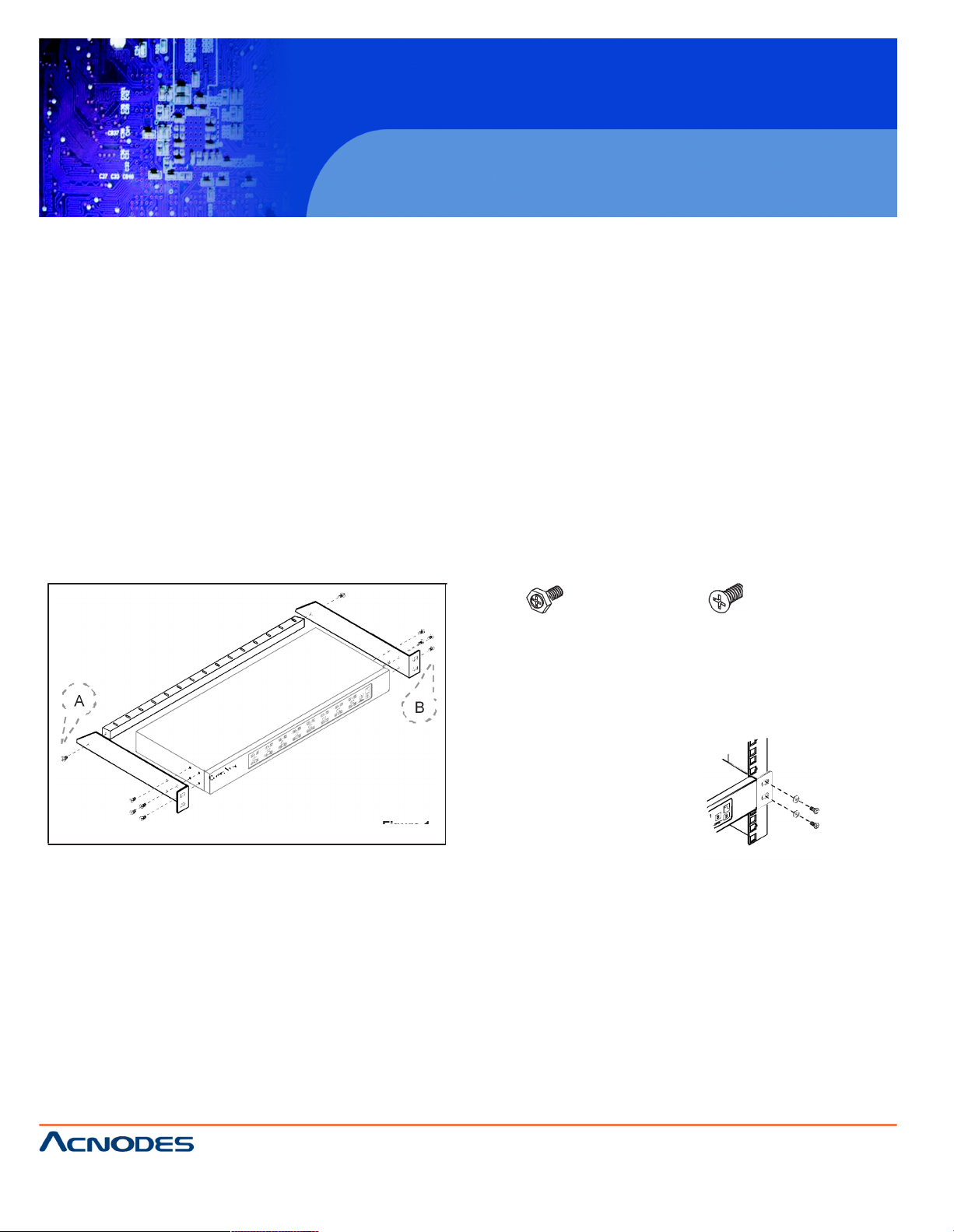
Installation for standalone KVM
Screw A: 2 pcs Screw B: 8 pcs
M3.2 x 4.5 m m M4 x 10 mm
¦ Install each bracket using screws
A
B provided shown in Figure 1.
¦ Fix the KVM into the rack
Figure 1.
1U Rackmount Combo Cat6 IP KVM switch
14628 Ce ntral Ave,
Chino , CA 91710
tel:909.597.7 588, fax:909.597.1939
© Copyright 2013 Acnodes, Inc.
All right s reser ved . Produc t descr ipt ion and product speci fi cat io ns
are subj ect to change w ith out n oti ce. F or lates t product inform ati on,
ple ase vis it Acnod es’ we b site at www.ac nodes.c om.
Page 5
Part 1. Combo Cat6 KVM
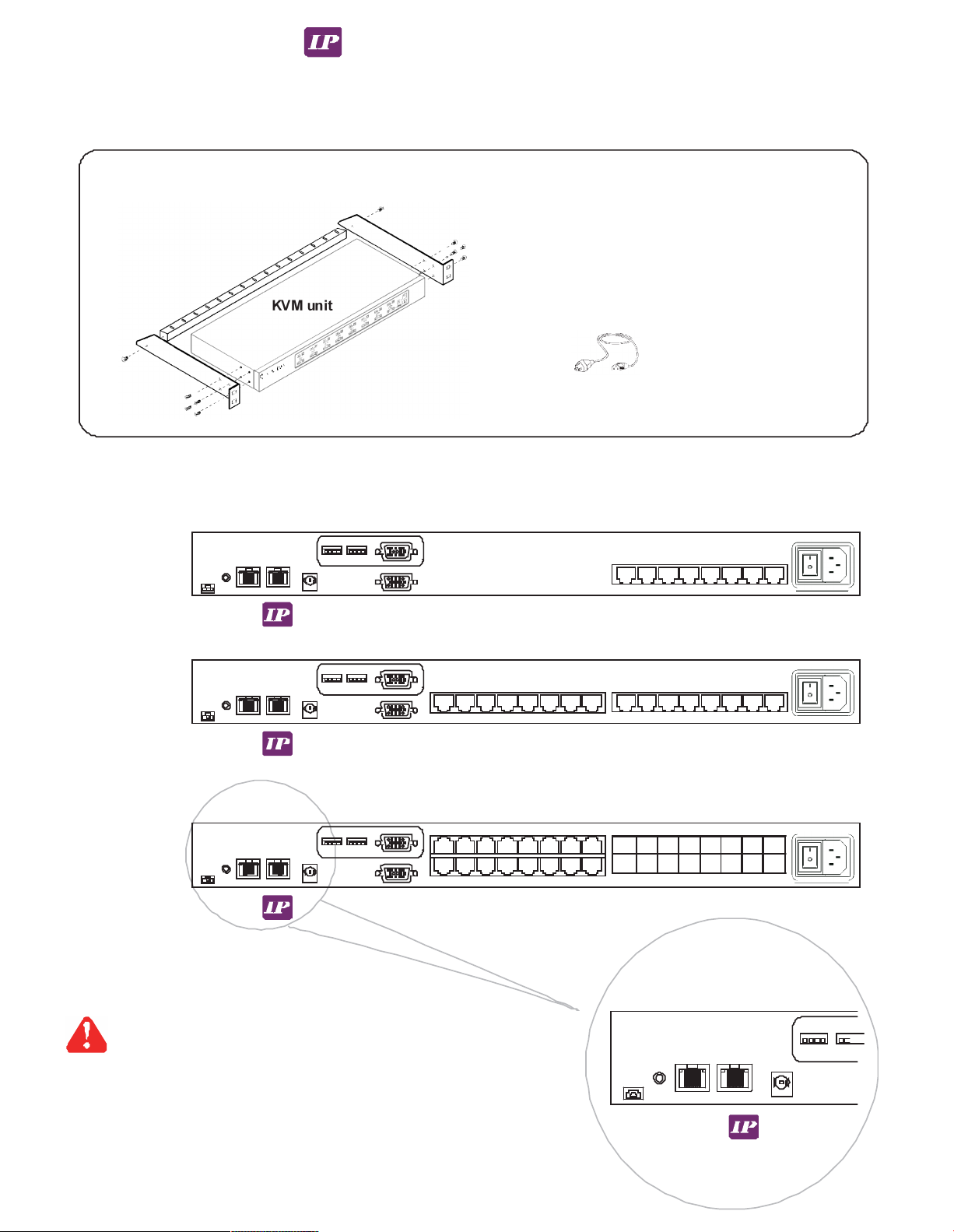
< 1.1 > Package Content
Combo Cat6 IP KVM
KCP802 / KCP1602 / KCP3202
• Combo IP KVM unit x 1
• Mounting set w/ bracket & screws x 1
• Power cord x 1
KVM unit
KCP802
Local
Console
IP console x 1
Local console x 1
8 7 6 5 4 3 2 1
KCP1602
1 6 15 14 13 12 11 10 9 8 7 6 5 4 3 2 1
Cascade
KCP3202
Local
Console
32 31 30 29 28 27 26 25 16 15 14 13 12 11 10 9
24 23 22 21 20 19 18 17 8 7 6 5 4 3 2 1
Multi port for remote PDU
CyberView IP KVM provides each RJ-45 Multi port to connect up
to 16 pcs of InfraPower remote PDUs, so the users can remotely
control & manage multi servers & max. 16 pcs remote PDU
Flash
USB
Multi
Page 6
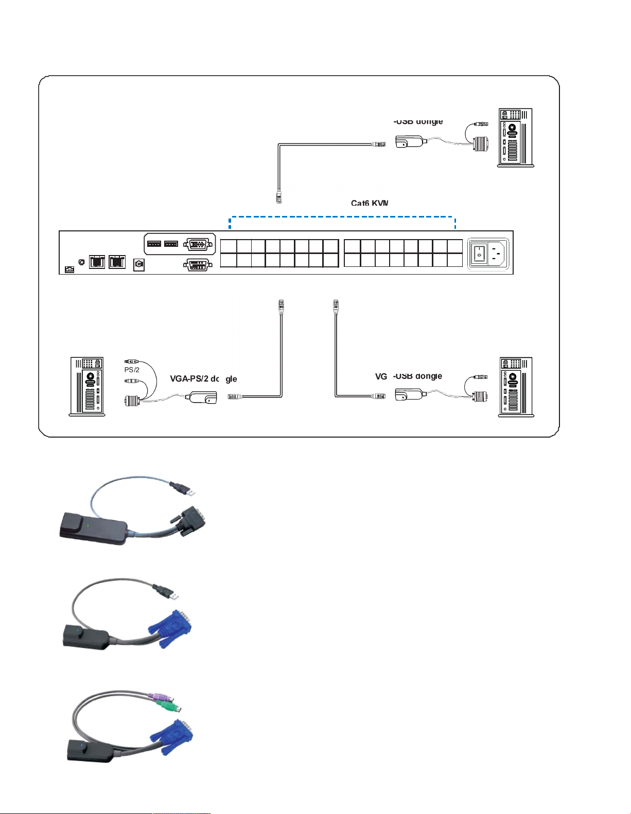
< 1.2 > KVM port & Cat6 dongle connection
Combo Cat6 IP KVM
USB Servers
CAT 5 / 6 cable
max. 40 meters
DVI-USB dongle
US B
DV I-D
Cat6 KVM port
32 31 30 29 28 27 26 25 16 15 14 13 12 11 10 9
24 23 2 2 21 20 19 18 17 8 7 6 5 4 3 2 1
PS/2 Servers USB Servers
PS/2
VGA
VGA-PS/2 dongle
CAT 5 / 6 cable
max. 40 meters
VGA-USB dongle
US B
VGA
DVI-USB dongle
¦ To connect DVI-D connector to the compute r’s video card
¦ To connect USB connector to the compute r’s USB port
VGA-USB dongle
¦ To connect DB-15 connector to the computer’s video card
¦ To connect USB connector to the compute r’s USB port
VGA-PS/2 dongle
¦ To connect DB-15 connector to the computer’s video card
¦ To connect PS/2 keyboard connector to the compute r’s keyboard port
¦ To connect PS/2 mouse connector to the compute r ’s mouse port
Page 7

KCP802/1602/3202
< 1.3 > IP & Local console connection
Combo Cat6 IP KVM
Local
USB
console
32 31 30 29 28 27 26 25 16 15 14 13 12 11 10 9
24 23 22 21 20 19 18 17 8 7 6 5 4 3 2 1
CAT 5 / 6 cable
max. 100m
Networ k device
hub or router
1U rackmount Combo Cat6 IP KVM Switch
14628 Ce ntral Ave,
Chino , CA 91710
tel:909.597.7 588, fax:909.597.1939
© Copyright 2013 Acnodes, Inc.
All righ ts reserved. Product descripti on and product speci ficat ions
are subj ect to change w ith out n oti ce. F or lates t product inform ati on,
ple ase vis it Acnod es’ we b site at www.ac nodes.c om.
Page 8

KCP802/1602/3202
< 1.4 > IP console setting
After the cable connection, please take the following steps to configure the IP KVM :
1. Download IPKVMsetup.exe
2. Double click IPKVMsetup.exe to configure the IP KVM by device setup as belo w.
3. Click Refresh Device to search the connected IP KVM
4. Select the M.A.C. address, which you want to setup, then click Query Device
5. Enter Super user login. The default is super
6. Enter Super user password. The default is pass
7. Enter the new super user password
8. Re-enter the new password
9. Change the desired IP address / Subnet mask / Gateway, then click Setup Device to confirm the setting to IP KVM
10. The default address is as below: --
¦ The single IP KVM m odel, such as KCP3202 - http://192.168.1.22
11. Open Internet Explorer ( I.E. ), version 6.0 or above
12. Enter the IP KVM address into the address bar
- For Single IP - http://192.168.1.22
13. Enter username ( default is super )
Password ( default is pass )
14. After successful login to IP KVM, the user will enter the main page of IP KVM
1U Rackmount Combo Cat6 IP KVM switch
14628 Ce ntral Ave,
Chino , CA 91710
tel:909.597.7 588, fax:909.597.1939
© Copyright 2013 Acnodes, Inc.
All right s reser ved . Produc t descr ipt ion and product speci fi cat io ns
are subj ect to change w ith out n oti ce. F or lates t product inform ati on,
ple ase vis it Acnod es’ we b site at www.ac nodes.c om.
Page 9

< 1.5 > KVM Cascade
¦ Cascade up to 8 levels, 256 servers
¦ Cascading multiple KVM with CBC -6 cascade cable.
Combo Cat6 IP KVM
Cascaded KVMs from level 2 to 8 must be the models of KC 801 / KC1601 / KC3201.
When multiple combo Cat6 KVMs cascade together, the master KVM at level 1 will take all control of
other slave KVM switches (e.g. level 2 to 8).
Master KVM
32 31 30 29 28 27 26 25 16 15 14 13 12 11 10 9
24 23 22 21 20 19 18 17 8 7 6 5 4 3 2 1
Cascade
Slave KVM
level 2
To console VG A port
16 15 14 13 12 11 10 9 8 7 6 5 4 3 2 1
KC1601
Slave KVM
level 3
16 15 14 13 12 11 10 9 8 7 6 5 4 3 2 1
KC1601
Slave KVM
level 4
16 15 14 13 12 11 10 9 8 7 6 5 4 3 2 1
KC1601
Slave KVM
level 5
16 15 14 13 12 11 10 9 8 7 6 5 4 3 2 1
KC 1601
Slave KVM
32 31 30 29 28 27 26 25 16 15 14 13 12 11 10 9
KC 3201
level 6
24 23 22 21 2 0 19 18 17 8 7 6 5 4 3 2 1
Slave KVM
32 31 30 29 28 27 26 25 16 15 14 13 12 11 10 9
KC 3201
level 7
24 23 22 21 2 0 19 18 17 8 7 6 5 4 3 2 1
Slave KVM
32 31 30 29 28 27 26 25 16 15 14 13 12 11 10 9
KC 3201
level 8
24 23 22 21 2 0 19 18 17 8 7 6 5 4 3 2 1
¦ 6ft Combo KVM cascade cable
Page 10

Cascaded PDUs
Dip switch no.
1 2 3 4 8
1st PDU
OnOnOnOnOff
2nd PDU
OffOnOnOnOff
3rd PDU
On
OffOnOn
Off
4th PDU
Off
OffOnOn
Off
5th PDU
OnOnOffOnOff
6th PDU
OffOnOffOnOff
7th PDU
On
Off
OffOnOff
8th PDU
Off
Off
OffOnOff
9th PDU
OnOnOn
Off
Off
10th PDU
OffOnOn
Off
Off
11th PDU
On
OffOnOff
Off
12th PDU
Off
OffOnOff
Off
13th PDU
OnOnOff
Off
Off
14th PDU
OffOnOff
Off
Off
15th PDU
On
Off
Off
Off
Off
16th PDU
Off
Off
Off
Off
Off
< 1.6 > IP Multi-port connection to remote PDU
Combo Cat6 IP KVM
IP KVM provides RJ-45 Multi port for the user to remotely control and manage servers & PDU togethe r.
Combo IP KVM
32 31 3 0 29 2 8 27 26 25 16 15 1 4 13 12 1 1 10 9
24 23 2 2 21 2 0 19 18 17 8 7 6 5 4 3 2 1
Other band IP KVM can NOT connect InfraPower PDU
Each RJ -45 Multi port connect max. 16 pcs of InfraPower PDU
To Multi port
1st level PDU 2nd level PDU 3rd level PDU
To L INK po rt
CAT. 5 / 6
CAT. 5 / 6
of the 1st P DU
LINK OU T
cab le
LINK OU T
cable
LINK OU T
CUR RENT ( A)
225
Up to 20 me ter s
CURRE NT( A)
225
Up t o 20 m eters
CURRE NT ( A)
225
ON DIP
1 2 3 4 5 6 7 8
ON DIP
1 2 3 4 5 6 7 8
ON DIP
1 2 3 4 5 6 7 8
RESET RESET RESET
To LINK port
of next PDU
( Up to 16 levels )
Dip switch setting
ON DIP ON DIP ON DIP
1 2 3 4 5 6 7 8 1 2 3 4 5 6 7 8 1 2 3 4 5 6 7 8
Using the dip switch no. 1, 2, 3, 4 & 8
to setup each PDU level acording to the table :
Page 11

< 1.6 > IP Multi-port connection to remote PDU
Combo Cat6 IP KVM
To access the PDU GUI, please enter the IP KVM main page and select
Remote Power > Start Service > Apply
1
PDU cascade port
L INK OUT
2 Current display
CURRE NT(A
)
225
ON
OF F
ON DIP
3
Dip switch
ON DIP
1 2 3 4 5 6 7 8
4 Reset button
RE SET
1 2 3 4 5 6 7 8
¦ For rackmount PDU,
2 3 4
on the front panel left ,
1
on the rear panel
Page 12

< 1.7 > Specifications
Combo Cat6 IP KVM
KCP802 KCP1602 KCP3202
¯
KVM Port
Number of ports: 8, 16 or 32
Connector: RJ-45
Connectivity: DVI-D / VGA connector dongle up to 40 meters (132 feet) via
Cat6 / Cat5 cable
¯
Local Console
Graphic connector: 1 x DB-15 VGA
Resolution: Up to 1600 x 1200
Input device: 2 x USB type A for keyboard & m ouse
¯
IP Remote Console
Connector: RJ45 Ethernet
User management: 15-user login, 1 x active user
Network protocol: DHCP / BOOTP / DNS
Security: SSL v3, RSA, AES, HTTP / HTTPs, CSR
Resolution: Up to 1600 x 1200
Browser: IE, Firefox, Safari, Netscape
¯
Expansion: Up to 256 servers by 8-level cascade
¯
Compatibility
Multi-platform: Mix PCs, SUNs, IBMs, HPs, DELLs Server
Support: Windows Vista / 2003 / XP / 2000, Linux, Netware, Unix
¯
Power
Input: 100 or 240V AC at 50 or 60 Hz via IEC type cord OR
AC / DC power adapter 12V@3.3A (optional)
Option DC: 12V / 24V / 48V DC input
Consumption: Max. 24 Watt, Standby 5 Watt
¯
Regulatory Approval: FCC, CE
¯
Environmental
Operating: 0 to 50°C
Storage: -5 to 60°C
Relative humidity: 90%, non-condensing
Shock: 50G peak acceleration (11ms, half-sine wave)
Vibration: 58~100Hz / 0.98G (11ms / cycle)
¯
Product Information
Dimension (W x D x H): 443 x 180 x 43.6 mm / 17.4 x 7.1 x 1.72 inch
Net weight: 3 kg / 6.5 lb
¯
Packing Information
Dimension (W x D x H): 500 x 400 x 90 mm / 19.7 x 15.7 x 3.5 inch
Gross weight: 5 kg / 11 lb
Page 13

Part 2. Usage
Combo Cat6 KVM Usage
2.1 KVM Button
Power ON
¦ Turn off all servers and KVM switches
¦ Make sure all cables / connectors are properly connected
¦ Recommend Power ON sequence is monito r, KVM switch finally computer
Front Panel - Port LED Indications
8 ports
Bank no. PC port LEDs Channel
button
Bank
button
16 ports
32 ports
Bank no. 7-Segment BANK LED indication
PC port LEDs Online : Blue LED on indicating a PC is connecting to the port
Active : Green LED on indicating a selected channel
Channel button Press to select channel from 01 to 32
Bank button Select the bank from 1 to 8
Page 14

KCP802/1602/3202
2.2 Password
Combo Cat6 KVM Usage
The password is enabled by default, the def ault password is “00000000” eight zeros (Do not use “0” on
number pad)
¦ Enable password
1. Press the KVM hotkey Scroll Lock + Scroll Lock + U
2. Logout the KVM by pressing the hotkey Scroll Lock + Scroll Lock + P
3. In SUPERVISOR level, enter “00000000” eight zeros in user name & password field
(Do not use “0” on number pad)
4. In USER level, press Space bar + Enter in user name & password field
Remark: Automatic logout after 10 minutes of inactivity
¦ Set your own user na me & password
1. Login the KVM in SUPERVISOR level by pressing “00000000” eight zeros in user name & password
field
2. Call KVM OSD menu by pressing the KVM hotkey Scroll Lock + Scroll Lock + Space Bar
3. Press F1 to the MAIN MENU
4. Select “USER SECURITY”
5. Set password in SUPE RVISOR & USER level
a. In the left- top row “S” (SUPE RVISOR), press Enter to set your own user name & password
b. In the row 1 to 8 (USER), press Enter to set your own user name & password
6. Press Enter to save the setting or pr ess Esc to cancel the editing without any change
Remark: a. B lank has underscore, while S PACE doesn’t have
b. Press any alphanumeric key to move to next input item. S PACE is treated as a valid
character
¦ Change your password
1. Login the KVM in SUPE RVISOR level by pressing your own user name & password
2. Call KVM OSD menu by pressing the KVM hotkey Scroll Lock + Scroll Lock + Space Bar
3. Press F1 to the MAIN MENU
4. Select “USER SECURITY”
5. Change password in SUPE RVISOR & USER level
a. In the left- top row “S” (SUPE RVISOR), press Enter to change your user name & password
b. In the row 1 to 8 (USER), press Enter to change your user name & password
6. Press Enter to save the setting or press Esc to cancel the editing without any change
Remark: a. B lank has underscore, while S PACE doesn’t have
b. Press any alphanumeric key to move to next input item. S PACE is treat ed as a valid
character
¦ Disable your password
1. Press the KVM hotkey Scroll Lock + Scroll Lock + U
2. Logout the KVM by pressing t he KVM hotkey Scroll Lock + Scroll Lock + P
3. You don’t need user name & pass word to access the KVM OSD m enu
¦ F orget your password
Please contact your supplier for further support
Remark:
¦ You must press the KVM hotkey within 2 seconds
¦ A beep sound will be heard for successful entering KVM hotkey
1U Rackmount Combo Cat6 IP KVM switch
14628 Ce ntral Ave,
Chino , CA 91710
tel:909.597.7 588, fax:909.597.1939
© Copyright 2013 Acnodes, Inc.
All right s reser ved . Produc t descr ipt ion and product speci fi cat io ns
are subj ect to change w ith out n oti ce. F or lates t product inform ati on,
ple ase vis it Acnod es’ we b site at www.ac nodes.c om.
Page 15

2.3 KVM OSD
OSD Menu
Combo Cat6 KVM Usage
OSD operation
next to the system name The PC is powered on
next to the sys tem name The PC is selected
F1 Access F1 MAIN MENU
F2 Logout the OSD menu
F3 Previous menu
Esc Cancel / Quit
Enter Complete / Switch to selected port
Switch to previous or next port
PgUp/PgDn Switch to previous bank or next bank
Display port 01 ~ 08 / 09 ~ 16 / 17 ~ 24 / 25 ~ 32
1 / 2 / 3 / 4
Remark: Display port 1 7 ~ 32 for 32 port model only
F1 Main Menu
01
LANGUAGE
OSD language change
02
PORT NAME EDIT
Define port name
03
PORT SEARCH
Quick searching by port name
04
USER SECURITY
Change password
05
ACCESS LIST
Define user access authority
06
HOTKEY
Change hotkey
07
TIME SETTINGS
Modify scan display time interval
08
OSD MOUSE
Modify OSD mouse speed
Page 16

Scroll Lock + Scroll Lock +
Space Bar
Calling OSD menu
Right-button mouse + Esc
Calling OSD menu
+
Port no.
Switch to specific port
Turn the buzzer ON and OFF
* Default the buzzer is ON
Logout the KVM if password security is
ON. Show up the status windows
2.4 KVM Hotkey & Remote Console Hotkey
Combo Cat6 KVM Usage
Local Console Hotkey Function
Scroll Lock
+
Scroll Lock
+
Switch to previous port
Scroll Lock
+
Scroll Lock
+
Switch to next port
Scroll Lock
+
Scroll Lock
+
PgUp / PgDn
Switch to previous bank or next bank
Scroll Lock + Scroll Lock + Bank no.
Scroll Lock + Scroll Lock + B
Scroll Lock + Scroll Lock + P
Advance hotkeys (for Supervisor login only)
Scroll Lock + Scroll Lock + S
Scroll Lock + Scroll Lock + R
Activate auto-scan mode for connected
servers
*Press any key to exit the auto-scan
mode
Reset all the KVM settings to factory
default
*Except User Security settings
Scroll Lock
+
Scroll Lock
+
U
Disable and enable password security
*Default security is ON
To enable / disable the screen saving
Scroll Lock
+
Scroll Lock
+
L
function and 10 minutes auto-logout
*Default the screen saving is OFF
Remarks:
¦ Example of “Scroll Lock + Scroll Lock + Bank no. + Port no.”
- Bank No. : 1 to 8
- Port No. : 01 to 32
- e.g. Bank 1 Port 4 : Scroll Lock + Scroll Lock + 1 + 0 + 4
- e.g. Bank 2 Port 16 : Scroll Lock + Scroll Lock + 2 + 1 + 6
¦ You must press the hotkey within 2 seconds
¦ A beep sound will be heard for successful entering
¦ The numeric keypad is not supported, while in OSD screen, the arrow keys, PgUp, PgDn, and Enter keys
are supports
Remote Console Hotkey Function
Scroll Lock + Scroll Lock + C Toggle switch between remote & local port
Scroll Lock + Scroll Lock + Q
Turn the buzzer ON & OFF
*Default the buzzer is ON
Scroll Lock + Scroll Lock + S
Activate auto-scan mode for remote & local port
*The scan time interval is 5 seconds
Scroll Lock + Scroll Lock + A Auto-adjust the video signal
Page 17

KCP802/1602/3202
2.5 DC Power 12V, 24V, 48V Input
Combo Cat6 KVM Usage
Model
12V
24V
48V
Input rating
Input voltage:
12-Volt
24-Volt
48-Volt
Input range:
9 ~ 18V
18 ~ 36V
36 ~ 75V
Input current
- No load
50 mA
50 mA
50 mA
- Full load
4950 mA
2450 mA
1220 mA
Output rating
Output voltage:
12-Volt
12-Volt
12-Volt
Output current:
4.16A
4.16A
4.16A
Efficiency
84%
85%
85%
Remarks:
¦ Package does not include power cord
1U rackmount Combo Cat6 IP KVM Switch
14628 Ce ntral Ave,
Chino , CA 91710
tel:909.597.7 588, fax:909.597.1939
© Copyright 2013 Acnodes, Inc.
All righ ts reserved. Product descripti on and product speci ficat ions
are subj ect to change w ith out n oti ce. F or lates t product inform ati on,
ple ase vis it Acnod es’ we b site at www.ac nodes.c om.
 Loading...