

Page 1

FPC 7161
Industrial Fanless Panel PC
© Copyrigh t 2013 Acnodes, Inc.
All rights reserved. Product description and product specifi cations
are subj ect to c han ge with out notic e. For l atest produ ct informati on,
please visit Acnodes’ web site at www.acnodes.c om.
14628 Central Ave,
Chin o, CA 91710
tel: 909.597.7588, fax:909.597.1939
User Manual
FPC 7161: 15.6” Industrial Fanless Multi-touch Panel PC with
Atom D2550 1.86GHz Processor
Page 2

FPC 7161
Disclaimers
This manua l h as been care fully ch ecked a nd b elieved to contain a ccurate info rma tion .
Acnod es Co rp. assumes no responsibility for a ny in fringe ments of pa tents o r any third
party’s rights, and an y liability arising from such u se .
Acnod es doe s n ot wa rrant or assu me an y lega l lia bility or respon sibility for the accuracy,
completene ss or usefulness of a ny info rma tio n in this document. Acnode s d oes not make a ny
commitmen t to u pdate the inf orm atio n in this m anual.
Acnod es reserve s th e right to ch ange o r revise this document a nd/or produ ct at any tim e
without not ice.
No pa rt o f this do cum ent ma y be re pro duced, stored in a retrie val syste m, or transmitted, in
any form or by any mea ns, electronic, mechanical, pho toco pying, recording, or oth erwise,
without the p rior written pe rm ission of Acno des Corp.
If you replace wrong batt eries, it causes th e dang er o f explosion. It is recomme nded by the
man ufacturer that yo u fo llow th e ma nufa ctu rer’s instructio ns t o o nly replace the same or
14628 Central Ave,
Chin o, CA 91710
tel: 909.597.7588, fax:909.597.1939
equ ivale nt t ype o f batte ry, and disp ose of used o nes.
Industrial Fanless Panel PC
© Copyrigh t 2013 Acnodes, Inc.
All rights rese rved. Product descri pt ion and produc t specif ication s
are subj ect to c han ge with out notic e. For l atest produ ct informati on,
please visit Acnodes’ web site at www.acnodes.c om.
Page 3

FPC 7161
Industrial Fanless Panel PC
© Copyrigh t 2013 Acnodes, Inc.
All rights reserved. Product description and product specifi cations
are subj ect to c han ge with out notic e. For l atest produ ct informati on,
please visit Acnodes’ web site at www.acnodes.c om.
14628 Central Ave,
Chin o, CA 91710
tel: 909.597.7588, fax:909.597.1939
Be fore getting sta rte d, rea d the follo wing important ca utions.
1. Be su re to groun d yourself to preve nt static ch arge wh en installing t he intern al
com ponen ts. Use a ground ing wrist st rap a nd place all electronic comp onents in any
static-shielde d devices. M ost e lectronic compon ents are sensitive to static electrical
cha rge .
2. Discon nect th e power cords f ro m FPC7161 be fore makin g a ny insta llatio n. Be sure
b oth the system an d t he external d evice s are turned OFF. Su dden surge of power
cou ld ruin sensitive com ponents. M ake sure the FPC7161 is prope rly groun ded.
3. Do not o pen t he system ’s to p cover. If opening the cove r f or maintena nce is a mu st, only
a trained t ech nician is allowed to do so. Integ rate d circu its on co mpute r boards are
sen sitive to sta tic electricity. To avoid dam aging chips f rom electro static disch arg e,
o bserve the fo llowin g p re cau tion s:
Before h andling a boa rd or int egrated circuit , touch an unpa inte d portion of the
system un it chassis for a fe w se con ds. This will he lp to discharge an y static
electricity on your bod y.
When h andling b oards a nd compon ents, wear a wrist-grounding strap, available
from mo st electronic com ponen t stores.
Page 4

Table of Contents
Disclaimers ........................................................................................ii
Safety Precautions ..............................................................................iii
Chapter 1 Introduction .........................................................................1
1.1 General Description .....................................................................1
1.2 Specifications .............................................................................2
1.3 Dimensions and Outliners .............................................................4
1.4 I/O Outlets ................................................................................5
1.5 Packing List ...............................................................................6
Chapter 2 Hardware and Installation.....................................................7
2.1 CF card Installation ......................................................................8
2.2 Open back cover ...........................................................................9
2.3 Serial Ports Interface ...................................................................11
2.3.1 COM1&COM2 Connector ................................................................11
2.4 Ethernet ....................................................................................12
2.5 Mounting:Panel/ Wall/ Desktop/ VESA.............................................13
2.5.1 VESA-ARM/Wall-Mount ...................................................................13
2.5.2 Panel-mount Kit Assembly ..............................................................13
2.6 HDD Installation..........................................................................14
2.7 DRAM Installation........................................................................16
2.8 Wireless LAN Card Installation ......................................................18
2.9 Power ........................................................................................20
Chapter 3 AMI BIOS Setup Utility .........................................................21
3.1 Starting ......................................................................................21
3.2 Navigation Keys ...........................................................................21
3.3 Main Menu ..................................................................................22
3.4 Advanced Menu ............................................................................23
3.5 Chipset Menu ...............................................................................30
3.6 Boot Menu ...................................................................................32
3.7 Security Menu ..............................................................................33
3.8 Save & Exit Menu .........................................................................34
Chapter 4 Drivers Installation .............................................................37
4.1 System ......................................................................................37
4.2 Touch Screen ..............................................................................37
4.3 Embedded O.S ............................................................................37
Page 5
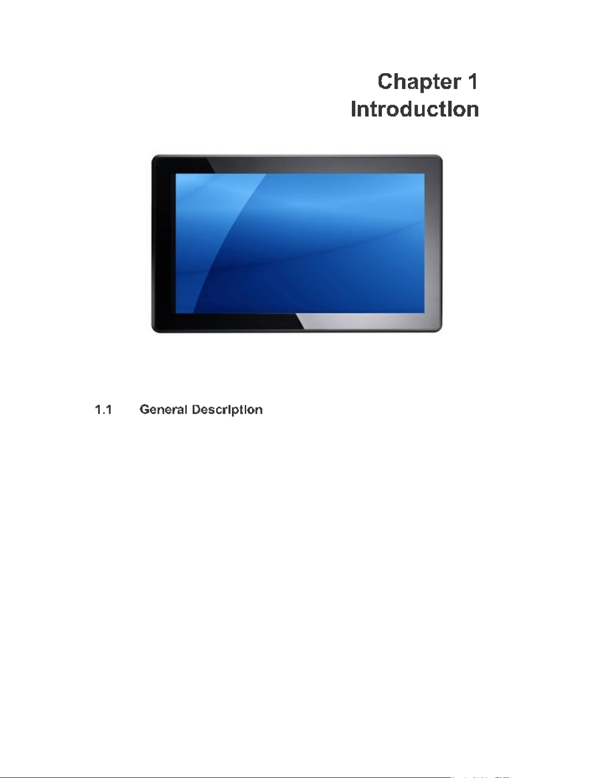
This chap ter contains ge neral inf orm atio n and detaile d spe cifications of the
FPC7161. Ch apter 1 in cludes the following sections:
-
Gene ral Descrip tio n
-
Spe cification
-
Dimen sions
-
I/ O Outlets
-
Packa ge List
z--
The FPC7161 adopts a 15 .6-inch WXGA TFT L CD with 300-nit brigh tness and an
TM
At om
proce ssor D2 550 1.86 GH z to pro vide exce llent com puting p erformance and
therma l resistan ce. This fanless pla tf orm is especially de signed for o pera tin g un der
hea vy-d uty environme nt including steel refinery, oil pipe, ship, m ach ine maker operating
systems and man y more. Having below ab ilities makes FPC716 1 surely a most
robust and cost-e ff ect ive solutio n.
FPC71 61 f eatures a technology o f wid e operating temp erature ran ge which allows it to work
betwe en -10°C to +5 0°C. It incorpora tes co mpact ID and f anless cooling syst em with a low
powe r Inte l
®
Ato m
TM
p ro cessor D25 50 1.86 GHz, making the platform a power-efficient
solu tion .
The FPC7161 ado pts a fan-less cooling syste m, which makes it especially su itable for
vibration-heavy en viron ments, best f or th e tra nsp orta tion , ship, and in dustrial machinery
markets. For high capa city storage requ ireme nt, FPC7 161 ca n work unde r 2.0G (5 ~
500 Hz, ran dom for Compa
design. Th e patent improves the syste m relia bilit y and susta ina bility.
ctFlash? ) in op era tion mod e with a paten t of anti-vibration
Page 6

FPC71 61 has a PCI Expre ss Min i Card slot fo r o ptio nal ad d-ons such as wireless
LAN card f or 802 .11 b/g co nnection s & 3G/ GPRS application, a nd more. It also provides an
optiona l fixed rotational WLAN a ntenn a f or wirele ss n etwork connection.
FPC71 61 utilizes one 204 -pin DDR3 1066 SODI MM syste m m emory ma x. up to
4GB, o ne SATA HDD and one CF. It provides ove r-curre nt pro tection -fu se an d a full se t of I/O
in cluding RS-23 2, RS-232 /422/ 485, USB 2.0 , aud io (line -o ut), and Gigabit Ethernet.
Ad ditiona lly, th is slim unit supports panel mou nt, wall moun t (optional), VESA mo unt (op tion al)
and d esktop stand (opti onal).
Main CPU Board
z
CPU: Atom
z
Sys te m Chi ps et: N M10 Express
z
Sys te m Memory:
On e 204-pin DDR3 1066 MHz SO-DIMM socket
Maxim um mem ory up to 4 GB
z
I/O System
BIOS: Am erica Megat ren ds BIOS
z
Stand I/O:
1 x RS-232/ 422/4 85, 1 x RS232
4 x USB 2 .0
z
Ethernet: 2 x RJ4 5 for Giga Ethernet
z
Audi o: 1x Line-out
z
Ex pa ns ion: 1 x Mini-card slot
z
Storage:
1 x 2.5” SATA HDD
1 x CompactFlash
z
Power Connector: Phoen ix p ower conn ect or
T M
D2 550 1.8 6GH z proce ssor on board
TM
Typ e II(optional)
Page 7

z
Disk dr ive housing: One 2 .5” SATA Drive
z
Net We ight: 5.0 Kgs (11.02 lb)
z
Dimension: 396. 8x 53 .9x 24 7.1mm
z
Oper ati on Temperature: -10C to 50C
z
Relative Humidi ty: 1 0% t o 95% @ 4 0C, Non-Cond ensing
z
Power Input: 10~30VDC with pho enix powe r connector
Page 8
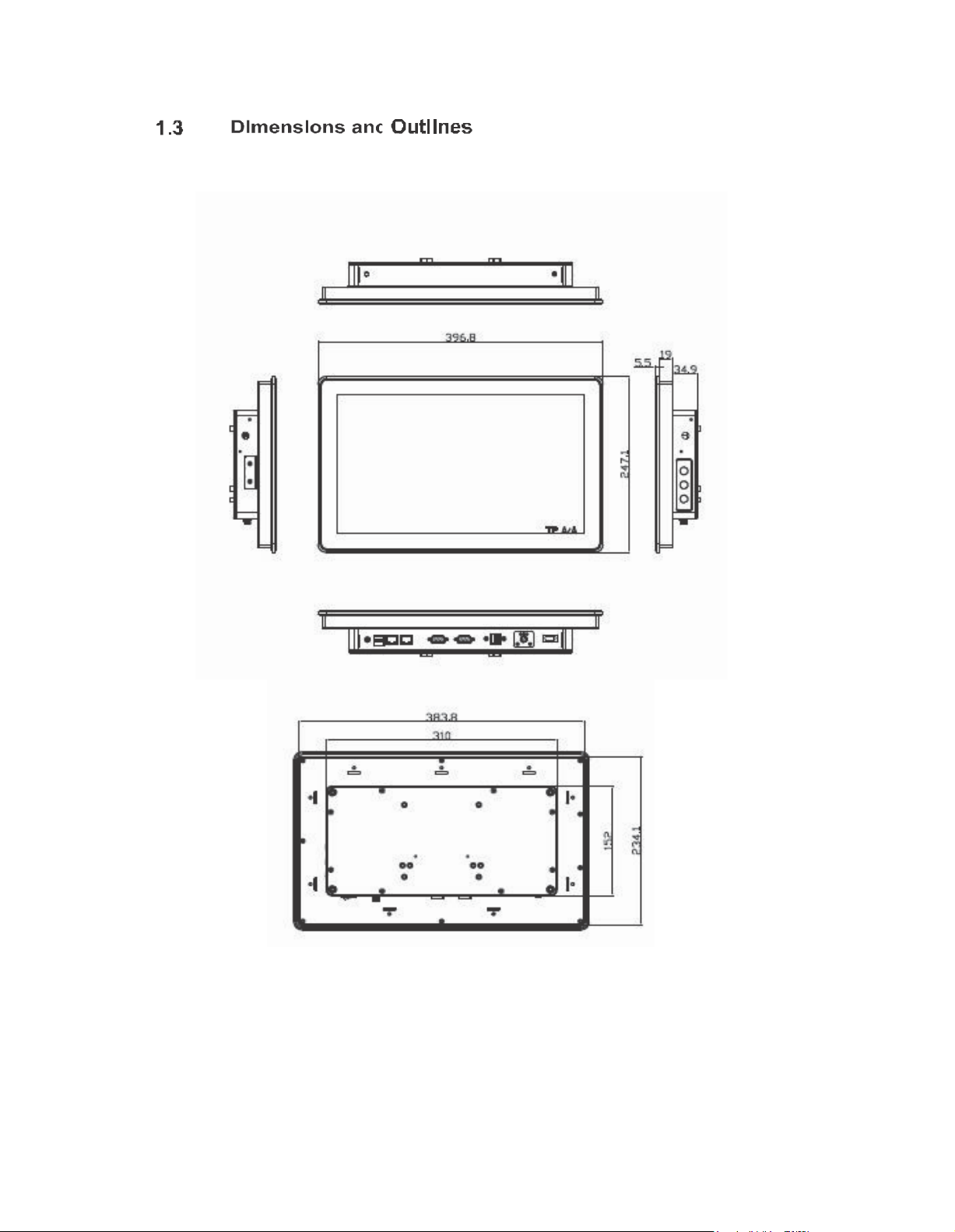
The following diagrams sho w th e dim ension s and ou tlines of FPC 71 61
Page 9
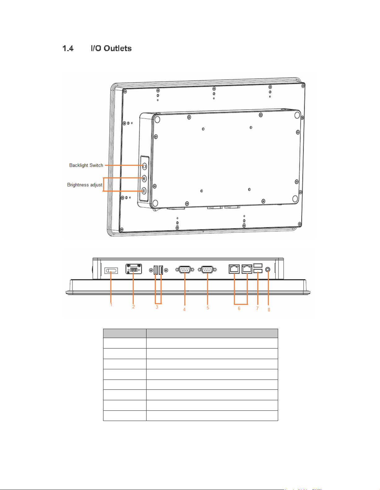
1
POWER SWITCH (ATX)
2
Termin al Blo ck for D C Power Input
3
2 x USB2.0
4
CO M 1 (RS-232/422/485)
5
CO M 2 (RS-232)
6
2 x ETHERNET
7
2 x USB2.0
8
Audio (Line-Out)
Please re fer t o the follo wing illustra tion fo r I/O lo cat ions of the FPC7 161.
Page 10

When you receive th e FPC7 161, t he bu ndled package should co ntain the
follo wing items:
FPC7161 unit x 1
Driver CD x 1
Phoenix connector x 1
Screws for HDD x 4
Panel mount k it x 6
If you cannot find the pack age or any items are missing, please contact Acnodes distributors
immediately.
Page 11

The FPC 7 161 provide s rich I/O ports a nd flexible expa nsions f or you to mee t
different dema nd, for example CF card. Th e ch apter will show yo u how to install the hardware.
It include s:
CompactFlash Card
Serial Port
Ethernet
Mouthing Method
Hard disk
DRAM
Wireless LAN Card
Power
Page 12
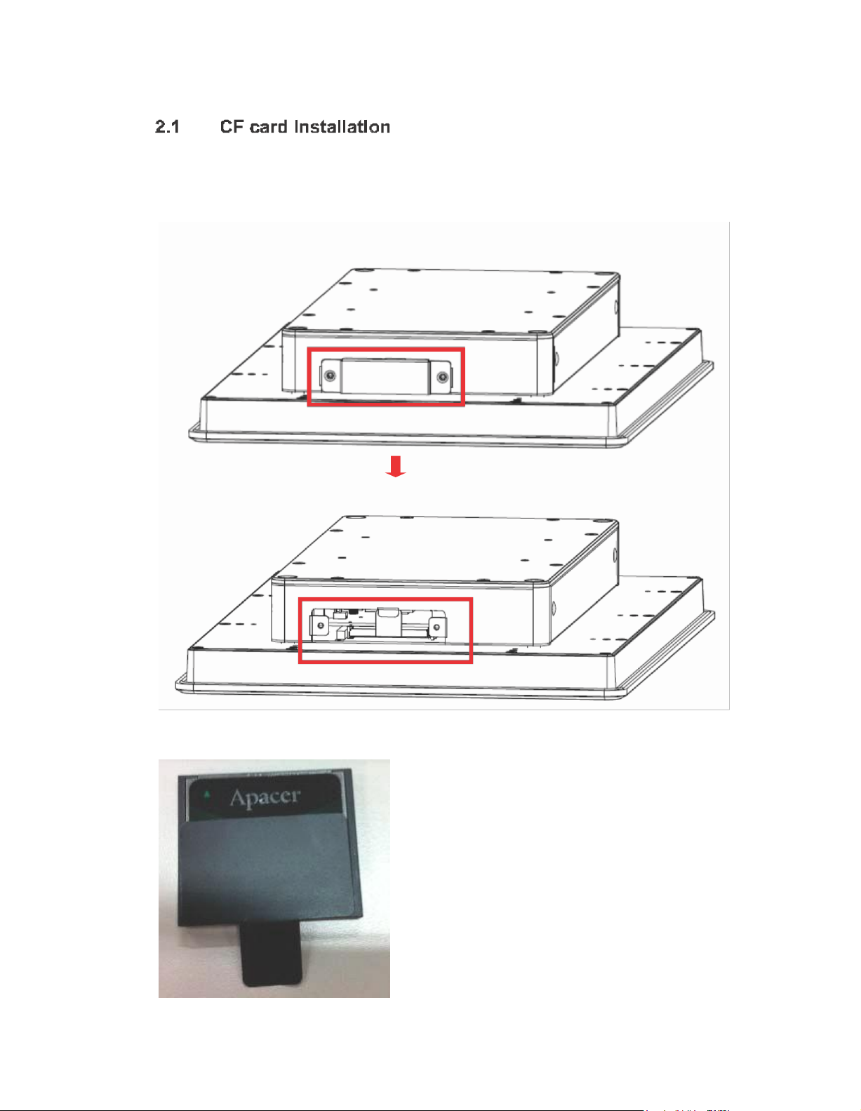
The FPC7 161 provide s one CF slot f or u sers t o install CompactFla sh™ card.
Please refer to the followin g instru ctions fo r installation:
Step 1 Open the cover, unscrew 2 screws on the chassis
Step 2 Stick the mylar on the CF card bottom side
Page 13

Step 3 Insert the CF card to the CF card slot, the finding the CF cover from the system package and screw it
This se ction tells users how to o pen back cover. Please follow the steps below.
Step 1 Unscrews on the back cover. Please refer the photo below
Page 14

Step 2 Remove the back cover
Page 15

RS-232 (D efault)
RS-422
C OM 1
RS-485
JP10
3-5, 4-6
C OM 1 Port
W/O Power: (3-5, 4-6)(Defaul t)
With Power: (1-3, 2-4)
JP11
C OM 2 Port
W/O Power: (3-5, 4-6)(Defaul t)
With Power: (1-3, 2-4)
3-5, 4-6
The FPC 716 1 h as fo ur serial ports. COM 1 is RS-2 32/42 2/485 and COM2 is
RS-232 . The fo llowin g ta ble shows you th e pin a ssignments o f this connector:
The COM 1 and C OM 2 is a stan dard DB-9 conn ecto r. This con nector is equippe d with
+5V level po wer capab ility o n DCD and +12V level on RI by sett ing JP1 0 and JP11.
Page 16

1
DC D
TX-
D ata-
2
RXD
TX+
D ata+
3
TXD
RX+
N .C
4
DT R
RX-
N .C .
5
GND
No use
N o use
6
DSR
No use
N o use
7
RT S
No use
N o use
8
CT S
No use
N o use
9
RI
No use
N o use
1 2 3 4 5 6 7 8
RJ-4 5
1
T X+ (Data transmi ss ion positi ve
2
T X- (Data transm ission negative)
3
R x+( Data reception positive)
4
R J45 termi nati on
5
R J45 termi nati on
6
R x- (Data rec epti on negative)
7
R J45 termi nati on
8
R J45 termi nati on
The pin assignme nt o f RS-232/RS-422/RS-485 is list ed o n the follo wing table. If yo u
n eed COM1 port to suppo rt RS-4 22 or RS-485 mod e, ple ase ref er to Jump er Settings
The FPC71 61 is equippe d with a h igh performance Plug an d Play Ethernet
in terface, f ull co mpliant with IEEE 8 02.3 standa rd, an d can be connected with a RJ-45 LAN
co nnector.
Please re fer to detailed pin assignmen t list below:
Page 17

There are 4 application options fo r the FPC 7161, Panel/Wall/De sktop/VESA
mou ntin gs.
The FPC716 1 provides VESA moun t: 100x100 mm . Screw four screws t o fix the kit in th e
b ack chassis.
The FPC7161 is de signed fo r pan el mou nt application. To m ount the FPC716 1,
t he sta ndard set of mo unting kit (included in t he system pa ckaging) is n eeded .
Page 18

The FPC7161 provide s a convenient Ha rd Disk Drive (HD D) bracket for u sers to
in sta ll 2.5 ” SATA HDD. Please follow th e ste ps:
Step 1 Refer section 2.2 to open the back cover
Step 2 Fix the HDD on the HDD tray by 4 screws
Page 19

Step 3 Plug the cables to connectors and screw the HDD tray on the bracket installation completes
Page 20

The FPC7161 pro vides one 2 04-pin DDR3 SODI MM socket t hat suppo rts syst em
mem ory up to 4 GB. Please follow steps b elow to install the mem ory mod ule s:
??
?
Ste p 1 Refer to section 2.2 to open the back cover
Ste p 2 Find the DIMM heatsi nk on the back cover. Sti ck the therma l pad on
it and rip the red mylar from i t
Step 3 Find out DIMM socket on mainboard
Page 21

Step 3 Insert the DRAM to the DIMM socket, and then push it down firmly until it is clipped by the socket
Installation completed
Page 22

The FPC71 61 provides one Mini card slot for user to install o ne wireless LAN card .
When installing the wire less LAN card, refer to th e following instruction s and illust ration:
Step 1 Refer to section 2.2 to open the back cover and find out mini-card slot on mainboard
Step 2 Insert the wireless LAN card to the slot. Push it down firmly until it is clipped by the slot.
Page 23

Step 3 F in d th e A nten n a c ab le and con n ect i t on wi rel ess L A N c ard
Step 4 Lift the rubber stopper from the top of back cover and screw the antenna cable.
….
Page 24

Step 5 Install the antenna on the antenna connector.
FPC 7 161 equ ips with a phoen ix type powe r co nnector. It adopts 10VDC to 30VDC.
Please follow the signs o n power co nnector to co nnect DC p ower source.
+: Power p ositive G: Safty g rou nd
Ё
:Power neg ative
Page 25

-
Left/Righ t
T he Left and Right <Arrow> keys allow you to select a setup screen.
Up/Down
T he U p and Down <Arrow> k eys al low you to sel ect a setup sc reen or
s ub-screen.
+- Plus/Minus
T he Plus and Mi nus <Arrow> keys all ow you to change the fi eld value of a
particul ar setup item .
Tab
T he <Tab> key al lows you to select setup fiel ds.
F1
T he <F1> key allows you to dis play the general help sc reen.
F2
T he <F2> key allows you to load previous values.
F3
T he <F3> key allows you to load optim ized defaul ts.
F4
T he <F4> key allows you to save any changes you have made and exit
s etup. Press the <F4> key to save your changes.
Esc
T he <Esc> key allows you to discard any changes you have made and exit
the s etup. Press the <Esc> key to exit the setup without s aving your
c hanges.
Enter
T he <Enter> key allows you to di spl ay or change the setup opti on listed for a
particul ar setup i tem. The <Enter> key can also allow you to di spl ay the
s etup sub- sc reens .
This ch apter provides use rs with d etailed description how to set u p basic syste m con figuration
through th e AMIBIOS8 BIOS se tup utility.
To e nter the setup scree ns, follow t he st eps be low:
Turn on t he co mpute r and press the <Del> key im mediately.
Afte r you press th e <Delete> key, the m ain BIOS setup me nu disp lays. Yo u ca n acce ss t he
othe r setup screen s from the m ain BIOS se tup menu , such as the Chipset and Power m enus.
The BIOS setup/ utilit y uses a key-b ase d naviga tion system ca lled ho t ke ys. Most of the BIOS
se tup utility ho t keys can be used at a ny time du ring the setup n avigation proce ss. The se keys
in clude <F1>, <F2>, <Enter>, <ESC >, <Arrow> keys, an d so on.
Page 26

When yo u first enter the Setup Utility, you will ente r the M ain setu p screen. You can a lways
return to the Main setup screen by select ing the M ain tab. There a re two Main Se tup o ptio ns.
They a re describ ed in th is sectio n. The M ain BIOS Se tup screen is shown be low
z
Use th is o ption to change the system time and da te. Highlig ht System Time or System
Date using th e <Arrow> keys. Enter new values through the keyboard. Press the <Ta b>
ke y o r the <Arrow> keys to mo ve b etween fields. The date m ust be e ntered in M M/DD/YY
format. The time is e ntered in HH:MM:SS format.
Page 27

z
This ite m can en able or disab le boo t o ptio n f or legacy ma ss storage de vice s with op tion
ROM.
The Advan ce d m enu also allows use rs to set configuratio n of the CPU and ot her system
devices. You can select any o f the items in the left frame of t he screen to go to the sub menus:
Ź
ACPI Settings
Ź
CPU Conf igu ra tion
Ź
IDE Con fig ura tion
Ź
USB Co nfiguration
Ź
NCT6 627UD Su perior IO Configuration
Ź
NCT6 627UD HW Monitor
For items marked with “f”, please p re ss <Enter> for more op tions.
Page 28

z
You can u se th is scre en to se lect options f or th e ACPI Con fig ura tion , an d cha nge the value
of the selecte d o ptio n. A descript ion of th e select ed item ap pears on th e right side of th e
screen.
Use this it em to sele ct the h ighe st ACPI sleep state the system will enter.
Page 29

z
This scree n sh ows the C PU Con figu ra tion , a nd you can ch ange the value of the se lected
option.
Use th is item to ena ble or d isable Hyper-Thre ading Te ch nology, which makes a sin gle
physical processor perform m ulti-taskin g fu nct ion as two lo gical o nes.
XD can prevent certa in classes of m alicious buffer overflow attacks when combined with a
su pporting OS (Wind ows Server 2 003 SP1, Wind ows XP SP2, SuSE Linux 9.2, Red Hat En
terprise 3 Update 3).
Page 30

z
The op tion al settings are: [Disa ble d]; [Ena bled ].
The optiona l settings are: [IDE]; [AHCI] .
Page 31

z
Yo u can use this scre en to select options fo r the USB C onfiguratio n, and cha nge th e valu e of
the selected option. A de scription of the sele cte d item ap pears o n the righ t side of the scre en.
The optiona l settings are: [Auto]; [Disab led ]; [Enabled] .
Page 32

z
Yo u can u se th is screen to select optio ns fo r the Supe r IO Conf igu ration, and cha nge the value
of t he selected op tio n. A descriptio n of the selected ite m appe ars on the righ t side of the
screen
Use this item to set paramet ers of seria l port 0~3
Page 33

z
This scre en shows the Hardware Health Co nfiguratio n, and a description of the selected item
app ears on th e right sid e of the screen .
Page 34

The Chipset m enu allows users to chang e the advanced chipset set tings. You can se lect an y
of th e ite ms in the left frame of the screen to g o to the sub me nus:
Ź
Host Bridg e Fo r items marke d with “f”, ple ase press <Ente r> f or more options.
Ź
Sou th Brid ge Fo r items marked with “f”, p lea se press <Ent er> for more options.
Page 35

z
This item is fo r memo ry freque ncy an d timin g settings. Press <En ter> to go to th e sub
menu .
Page 36

The Bo ot menu a llows u sers to cha nge boo t o ptions of t he syst em.
z
Use this item to set numb er o f se con ds to wait for setup activation ke y.
Use this ite m t o select th e p ower-on state for the Num Lock.. The optional settings a re: [On];
[Off].
If Upo n R equest is selected, GA20 ca n be disab led usin g BIOS se rvices. If Always is se lected ,
disa bling G2 0 is not allowe d; this option is usefu l when any RT code is e xecute d a bove 1 MB.
Se t display mo de for option ROM. Configuration options are Force BIOS and Keep Cu rrent.
If th is item is e nabled, this fun ction makes the option ROM to trap Int errup t 1 9.
These are settings for boot priorit y. Spe cify th e boo t device priority seq uence fro m the
available devices.
Page 37

The Se cu rity men u allows use rs to ch ange the securit y sett ings for the system.
This ite m indica tes whet her an adm inistra tor passwo rd has been set. If the passw ord has been
in sta lle d, Insta lled displays. If not, Not I nsta lled displays.
This ite m indica tes wheth er an user password ha s been set. If the passwo rd has been installed ,
Installed displays. If not, Not I nsta lled
?
displays.
?
Page 38

?
The Save & Exit me nu a llows users to load you r syste m configuration with o ptim al or fail-safe
def ault values.
When you have completed t he system configuration change s, select this option to leave Set up
and rebo ot the compute r so th e new system co nfig uration param eters ca n ta ke effe ct. Se lect
Sa ve Ch ange s a nd Exit from the Exit men u and press <Ente r>. Se lect Ok to save ch anges
and e xit.
Se lect this option to quit Se tup without making any perman ent changes to the system
configuratio n. Se lect Discard Cha nges and Exit f ro m the Exit menu and pre ss <Ente r>. Se lect
Ok to d isca rd change s and exit.
When you have completed t he system configuration change s, select this option to leave Set up
and rebo ot the compute r so th e new system co nfig uration param eters ca n take effe ct. Sele ct
Sa ve Chan ges an d Re set from the Sa ve & Exit menu and press <Enter>. Sele ct Yes to save
change s and reset.
?
Se lect this option to quit Se tup without making any perman ent changes to the system
configuratio n and reb oot th e co mpute r. Select Discard Change s an d Reset from th e Sa ve &
Exit menu an d press <Enter>. Sele ct Yes to discard ch anges and reset.
When you have completed th e system configuration cha nges, select this opt ion to save
change s. Select Save Cha nges from the Save & Exit menu and press <Ente r>. Select ye s to
save chan ges.
Page 39

Se lect this option to quit Se tup withou t making any permane nt changes to the system
configuratio n. Se lect Discard Chan ges from th e Save & Exit men u and press <En ter>. Select
Ye s to disca rd change s.
It aut omatica lly sets all Set up o ptions to a comp lete set of def ault settings whe n you sele ct this
option. Sele ct Restore Defau lts from th e Save & Exit me nu and p ress <En ter>.
Se lect th is op tion to save syste m configuration ch anges don e so f ar as User De faults. Select
Sa ve as User De faults from the Save & Exit menu an d pre ss <Enter>.
It automa tically sets all Set up options to a comp lete set of User Def aults when you select th is
option. Sele ct Restore Use r Def aults f ro m the Sa ve & Exit me nu and p re ss <Enter>.
Se lect a drive to immed iate ly bo ot that de vice rega rd less of th e current boo t ord er.
Page 40

Touch Sc reen
projected capaci tive mul ti-touch
Touch Sc reen Controller
Mastouch USB Touch Screen Controller IC
Com munications
USB interface
Power Suppl y
5V
Power Cons um ption
40mA
Input M ethod
Finger or Cap.Stylus
Resoul ation
25ppi(Min.)
Note: Base on WIN7 definition, ppi(Pixcel per inch)
Win7 USB Driver
Non-Dri ver
Cali bration
Non-Cal ibrati on
FPC7161 sup ports Windo ws 7 32 -bit. To facilitate the installatio n of system driver,
please carefully re ad the instructions in this chapte r bef ore start installing.
The FPC71 61 uses th e pro jected ca pacitive multi-tou ch . The sp ecification is liste d
below.
It also can drive the to uch pa nel to g et two fingers tou ch function that based on t he Windows 7
su pport.
z
The FPC71 61 provides the WES 7E.
 Loading...